JP6607138B2 - Exhaust gas recirculation control device for internal combustion engine - Google Patents
Exhaust gas recirculation control device for internal combustion engine Download PDFInfo
- Publication number
- JP6607138B2 JP6607138B2 JP2016087887A JP2016087887A JP6607138B2 JP 6607138 B2 JP6607138 B2 JP 6607138B2 JP 2016087887 A JP2016087887 A JP 2016087887A JP 2016087887 A JP2016087887 A JP 2016087887A JP 6607138 B2 JP6607138 B2 JP 6607138B2
- Authority
- JP
- Japan
- Prior art keywords
- cylinder
- egr
- knock
- internal combustion
- combustion engine
- Prior art date
- Legal status (The legal status is an assumption and is not a legal conclusion. Google has not performed a legal analysis and makes no representation as to the accuracy of the status listed.)
- Active
Links
Images


Classifications
-
- Y—GENERAL TAGGING OF NEW TECHNOLOGICAL DEVELOPMENTS; GENERAL TAGGING OF CROSS-SECTIONAL TECHNOLOGIES SPANNING OVER SEVERAL SECTIONS OF THE IPC; TECHNICAL SUBJECTS COVERED BY FORMER USPC CROSS-REFERENCE ART COLLECTIONS [XRACs] AND DIGESTS
- Y02—TECHNOLOGIES OR APPLICATIONS FOR MITIGATION OR ADAPTATION AGAINST CLIMATE CHANGE
- Y02T—CLIMATE CHANGE MITIGATION TECHNOLOGIES RELATED TO TRANSPORTATION
- Y02T10/00—Road transport of goods or passengers
- Y02T10/10—Internal combustion engine [ICE] based vehicles
- Y02T10/40—Engine management systems
Description
本発明は、内燃機関の排気還流制御装置に関する。 The present invention relates to an exhaust gas recirculation control device for an internal combustion engine.
内燃機関において、排気をEGR(Exhaust Gas Recirculation)ガスとして吸気側に還流させる排気還流管を備えることにより、排気のNOx低減および燃費の改善を実現するEGRが知られている。 In an internal combustion engine, EGR is known that realizes NOx reduction of exhaust gas and improvement of fuel consumption by providing an exhaust gas recirculation pipe that recirculates exhaust gas as exhaust gas recirculation (EGR) gas to the intake side.
EGRでは、EGRガス分配の気筒間ばらつきや、デポジット堆積によるEGRガス流量の気筒間ばらつきが発生し、気筒間の燃焼のばらつきにつながる。 In EGR, variations between cylinders in EGR gas distribution and variations in EGR gas flow rate due to deposit accumulation occur between cylinders, leading to variations in combustion between cylinders.
特許文献1では、各気筒につながる吸気枝通路にそれぞれ吸気温センサを配置し、各気筒の吸気温のばらつきからEGRガス分配の気筒間バラつきを判定し、吸気マニホールド前に設けられたEGR弁の弁開度を小さくすることによりばらつきを解消している。
In
特許文献2では、触媒前センサにより空燃比ずれ異常が発生している気筒を判定し、異常発生前後のノック指標値により、空燃比ずれ異常が、EGRガス分配のばらつきによるものか、燃料噴射量のばらつきによるものかを判定している。
In
しかしながら、特許文献1に記載のものは、EGRガス分配の気筒間ばらつきがあると判定した場合、EGR弁の弁開度を小さくしてEGRガス量を減らすことでばらつきを解消しているため、EGR率の低下により燃費の悪化や排気のNOx増大につながる。
However, since the thing of
特許文献2に記載のものは、EGRガス分配のばらつきが発生している気筒を特定することは可能であるが、EGRガス分配のばらつきの気筒間差は計測していない。このため、燃焼のばらつきを抑制する際に、ばらつきを抑制するための制御量を算出することができない。
Although it is possible to specify the cylinder in which the dispersion | variation in EGR gas distribution has generate | occur | produced in the thing of
そこで、本発明は、EGRガス分配の気筒間ばらつきを抑えて、燃費を向上させることができる内燃機関の排気還流制御装置を提供することを目的としている。 SUMMARY OF THE INVENTION An object of the present invention is to provide an exhaust gas recirculation control device for an internal combustion engine that can suppress the variation between cylinders in EGR gas distribution and improve fuel efficiency.
上記課題を解決するため本発明は、複数の気筒と、前記気筒のそれぞれに吸気を導入する複数の吸気分岐管とを備えた内燃機関の排気還流制御装置であって、前記内燃機関の排気の一部をEGRガスとして前記吸気分岐管のそれぞれへ還流させる排気還流管と、前記内燃機関の運転状態に基づいて前記EGRガスの還流量を調整するよう前記吸気分岐管のそれぞれに設けられたEGRバルブと、前記内燃機関のノッキング振動を検出するノックセンサと、前記ノックセンサの検出結果に基づいて前記内燃機関の気筒毎のノック強度を検出し、前記気筒毎のノック強度の差分値の最大値が所定値を超える場合に前記気筒毎の前記EGRガスの還流量を調整する制御部と、を備えるものである。
In order to solve the above problems, the present invention provides an exhaust gas recirculation control device for an internal combustion engine comprising a plurality of cylinders and a plurality of intake branch pipes for introducing intake air into each of the cylinders. An exhaust gas recirculation pipe that recirculates a part of each as EGR gas to each of the air intake branch pipes, and an EGR provided in each of the air intake branch pipes to adjust the recirculation amount of the EGR gas based on the operating state of the internal combustion engine A valve, a knock sensor for detecting knocking vibration of the internal combustion engine, a knock intensity for each cylinder of the internal combustion engine based on a detection result of the knock sensor, and a maximum value of a difference value of the knock intensity for each cylinder And a controller that adjusts the recirculation amount of the EGR gas for each cylinder when the value exceeds a predetermined value .
このように本発明によれば、EGRガス分配の気筒間ばらつきを抑えて、燃費を向上させることができる内燃機関の排気還流制御装置を提供することができる。 As described above, according to the present invention, it is possible to provide an exhaust gas recirculation control device for an internal combustion engine that can suppress the variation between cylinders in EGR gas distribution and improve fuel efficiency.
以下、図面を参照して、本発明の実施形態に係る内燃機関の排気還流制御装置について詳細に説明する。 Hereinafter, an exhaust gas recirculation control apparatus for an internal combustion engine according to an embodiment of the present invention will be described in detail with reference to the drawings.
図1において、本発明の一実施形態に係る内燃機関の排気還流制御装置を搭載した車両1は、内燃機関型のエンジン2と、制御部としてのECU(Engine Control Unit)3とを含んで構成されている。
In FIG. 1, a
エンジン2は、少なくとも1つ以上、例えば4つの気筒を有する直列4気筒で構成されている。なお、エンジン2は、直列4気筒に限らず、例えばV型エンジン等であってもよいし、気筒数も特に4つに限定されるものではない。
The
エンジン2は、不図示のピストン、シリンダ、コネクティングロッド等を備え、ピストンが気筒を2往復する間に吸気行程、圧縮行程、膨張行程及び排気行程からなる一連の4行程を行なう4サイクルのエンジンによって構成されている。
The
シリンダに収納されたピストンは、コネクティングロッドを介してクランクシャフトに連結されている。コネクティングロッドは、ピストンの往復運動をクランクシャフトの回転運動に変換するようになっている。 The piston housed in the cylinder is connected to the crankshaft via a connecting rod. The connecting rod converts the reciprocating motion of the piston into the rotational motion of the crankshaft.
シリンダヘッドには、点火プラグ4と、吸気ポート11と、排気ポート21とが設けられている。点火プラグ4は、燃焼室内に電極を突出させた状態でシリンダヘッドに配設され、ECU3によってその点火時期が調整される。
The cylinder head is provided with an
吸気ポート11には、吸気分岐管としてのインテークマニホールド13が設けられている。インテークマニホールド13は、空気を燃焼室に導入する。インテークマニホールド13は、外気を吸入するための吸気管14に接続されている。この吸気管14の内部には、吸気ポート11と連通する吸気通路14aが形成されている。
The
吸気ポート11には、吸気弁12が設けられている。吸気弁12は、吸気通路14aと燃焼室とを連通または遮断するように開閉されるようになっている。
The
排気ポート21には、燃焼室のなかで混合気の燃焼によって発生した排気を車外に排出するためのエキゾーストマニホールド23が設けられている。エキゾーストマニホールド23は、排気管24に接続されている。この排気管24の内部には、排気ポート21と連通する排気通路24aが形成されている。
The
排気ポート21には、排気弁22が設けられている。排気弁22は、排気通路24aと燃焼室とを連通または遮断するように開閉されるようになっている。
The
この排気管24には、三元触媒25が設けられている。三元触媒25は、エンジン2の燃焼室から排出された排ガス、すなわち既燃ガスを浄化するようになっている。
A three-
このエンジン2には、吸気通路14aと排気通路24aとを連通する排気還流管41が設けられている。排気還流管41は、排気の一部を吸気側に還流させるEGRを行なわせるようになっている。排気還流管41は、分岐して各気筒のインテークマニホールド13に接続する。排気還流管41のインテークマニホールド13との接続部の排気が還流してくる方向の上流側には、各気筒に対応した排気の還流量を調整する排気還流制御弁としてのEGRバルブ42が設けられている。
The
EGRバルブ42は、ECU3に電気的に接続されている。EGRバルブ42は、ECU3からの指令信号に応じてバルブ開度が制御されることで、各気筒に還流させる排気の量を調整するようになっている。
The
ECU3は、CPU(Central Processing Unit)と、RAM(Random Access Memory)と、ROM(Read Only Memory)と、フラッシュメモリと、入力ポートと、出力ポートとを備えたコンピュータユニットによって構成されている。
The
このコンピュータユニットのROMには、各種制御定数や各種マップ等とともに、当該コンピュータユニットをECU3として機能させるためのプログラムが記憶されている。すなわち、CPUがROMに記憶されたプログラムを実行することにより、当該コンピュータユニットは、ECU3として機能する。
The ROM of the computer unit stores a program for causing the computer unit to function as the
ECU3の入力ポートには、クランク角度センサ45、アクセル開度センサ46、ノックセンサ47等の各種センサ類が接続されている。
Various sensors such as a
クランク角度センサ45は、エンジン2の回転に伴い所定クランク角度毎に矩形状のクランク角信号を出力する。ECU3は、このクランク角信号に基づいてエンジン2の機関回転数であるエンジン回転数を算出する。
The
アクセル開度センサ46は、運転者による図示しないアクセルペダルの踏み込み量をアクセル開度として検出する。ノックセンサ47は、エンジン2のノッキング振動を検出し、ノッキング振動の大きさに応じたノック信号を出力する。
The
一方、ECU3の出力ポートには、上述の点火プラグ4、EGRバルブ42等の各種制御対象類が接続されている。
On the other hand, various control objects such as the
ECU3は、運転者の操作によるアクセル開度に基づきエンジン2の要求負荷を算出し、その要求負荷に応じてエンジン2の吸入空気量や燃料噴射量や点火時期を算出する。そして、ECU3は、算出した吸入空気量や燃料噴射量や点火時期になるように不図示のスロットルバルブやインジェクタや点火プラグ4を制御してエンジン2の運転状態を制御する。
The ECU 3 calculates the required load of the
ECU3は、エンジン2の運転状態に応じてEGRを実行させる(オン)か、または実行させない(オフ)か、を切り替えるようになっている。例えば、ECU3は、エンジン回転数とエンジン負荷とによってオンまたはオフが決まるEGRマップによりEGRのオンとオフを切り替える。このEGRマップは、EGRをオンにするEGRオン領域と、EGRをオフにするEGRオフ領域とに分けられていて、エンジン回転数とエンジン負荷とによってどちらの領域に入るかが決まるようになっている。このEGRマップは、予め実験的に求められ、ECU3のROMに記憶されている。
The ECU 3 is configured to switch whether the EGR is executed (ON) or not (OFF) according to the operating state of the
ECU3は、例えば、エンジン回転数とアクセル開度からエンジン負荷が決まるマップによりエンジン負荷を求めるようになっている。エンジン負荷のマップは、予め実験的に求められ、ECU3のROMに記憶されている。
For example, the
ECU3は、EGRがオンの状態において、気筒毎のノック強度に基づき、EGRガス分配の気筒間ばらつきが大きいと判定したとき、各気筒のEGRガス量を調整する。
The
ECU3は、各気筒の燃焼時期に基づき、ノックセンサ47により各気筒のノック強度を算出する。ECU3は、例えば、ノックセンサ47が検出したエンジン2のシリンダブロックの振動周波数から各気筒のノック強度KSi(iは、気筒番号)を算出する。
The
ECU3は、各気筒のノック強度KSiの差分値の最大値が所定値を超える状態が所定時間Y[s]以上継続した場合、EGRガス分配の気筒間ばらつきが大きいと判定する。所定値及び所定時間は、予め実験的に求められ、ECU3のROMに記憶されている。
The
ECU3は、例えば、図2に示すように、各気筒のノック強度KSiを記憶している。ECU3は、ある気筒の新しいノック強度KSiを算出すると、当該気筒の記憶しているノック強度KSiを消去し、新しいノック強度KSiで更新する。ECU3は、新しいノック強度KSiを算出するごとに各気筒のノック強度の差分値を算出し、EGR分配の気筒間ばらつきを判定する。
For example, as shown in FIG. 2, the
ECU3は、各気筒のノック強度KSiが予め設定されたノック閾値以上であれば点火リタード要求とする。ECU3は、ノック強度KSiとノック閾値との差分に応じて点火リタード要求量を算出する。点火リタード要求量は、ノック強度KSiとノック閾値との差分が大きいほど大きい値となる。
The
ECU3は、各気筒のノック強度KSiが予め設定されたノック閾値未満であれば点火進角要求とする。ECU3は、ノック強度KSiとノック閾値との差分に応じて点火進角要求量を算出する。点火進角要求量は、ノック強度KSiとノック閾値との差分が大きいほど大きい値となる。
The
ECU3は、点火リタード要求となった気筒については、EGRガス量が少ないと判定し、点火リタード要求量からEGRバルブ開度増加分補正値を算出し、EGRバルブ42の開度を増やす。
The
ECU3のROMには、EGR率増大による失火を防ぐため、EGRバルブ開度増の制限値が予め記憶されている。ECU3は、EGRバルブ開度増加分補正値が開度増制限値以下であれば、EGRバルブ開度増加分補正値だけEGRバルブ42の開度を増やす。
In the ROM of the
ECU3は、EGRバルブ開度増加分補正値が開度増制限値を超えていれば、開度増制限値だけEGRバルブ42の開度を増やし、EGRバルブ開度増加分補正値からの不足分だけ点火リタードを実行する。
If the EGR valve opening increase correction value exceeds the opening increase limit value, the
ECU3は、点火進角要求となった気筒については、EGRガス量が多いと判定する。ECU3は、点火進角要求量が予め設定された進角制限値を超えた場合は、EGR過多による過進角と判定し、点火進角要求量からEGRバルブ開度減少分補正値を算出し、EGRバルブ42の開度を減らす。点火進角要求量が予め設定された進角制限値以下の場合、ECU3は、点火進角要求量だけ点火時期を進角させる。
The
ECU3のROMには、EGR率減少によるノックの発生を防ぐため、EGRバルブ開度減の制限値が予め設定されている。ECU3は、EGRバルブ開度減少分補正値が開度減制限値以下であれば、EGRバルブ開度減少分補正値だけEGRバルブ42の開度を減らす。
In the ROM of the
ECU3は、EGRバルブ開度減少分補正値が開度減制限値を超えていれば、開度減制限値だけEGRバルブ42の開度を減らし、EGRバルブ開度減少分補正値からの不足分だけ点火進角を実行する。
If the EGR valve opening decrease correction value exceeds the opening decrease limit value, the
ノック強度の判定は、各気筒の燃焼時期に合わせて実行され、判定の結果に基づくEGRバルブ42の制御や点火時期の制御は、該当気筒の次回の燃焼時期に合わせて実行される。
The determination of the knock intensity is executed in accordance with the combustion timing of each cylinder, and the control of the
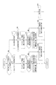
以上のように構成された本実施形態に係る内燃機関の排気還流制御装置による排気還流制御処理について、図3及び図4を参照して説明する。なお、以下に説明する排気還流制御処理は、ECU3が動作を開始すると開始され、各気筒の燃焼時期に同期して実行される。
Exhaust gas recirculation control processing by the exhaust gas recirculation control apparatus for an internal combustion engine according to the present embodiment configured as described above will be described with reference to FIGS. 3 and 4. Note that the exhaust gas recirculation control process described below is started when the
ステップS1において、ECU3は、エンジン回転数と、エンジン負荷と、エンジン2の冷却水温度とからエンジン2の運転状態がEGRオン領域か否かを判定する。EGRオン領域でないと判定した場合、ECU3は、処理を終了する。
In step S1, the
EGRオン領域であると判定した場合、ステップS2において、ECU3は、ノックセンサ47により今回燃焼時期の気筒のノック強度を算出し、該当気筒のノック強度を更新する。
When it is determined that it is in the EGR on region, in step S2, the
ステップS3において、ECU3は、気筒毎のノック強度の差分値の最大値が所定値を超える状態が所定時間Y[s]以上継続しているか否かを判定する。
In step S3, the
気筒毎のノック強度の差分値の最大値が所定値を超える状態が所定時間Y[s]以上継続していると判定した場合、ステップS4において、ECU3は、今回燃焼時期の気筒について、図4に示すような、気筒別ノック制御を実行する。
When it is determined that the state in which the maximum difference value of the knock intensity for each cylinder exceeds the predetermined value continues for the predetermined time Y [s] or longer, in step S4, the
一方、気筒毎のノック強度の差分値の最大値が所定値を超える状態が所定時間Y[s]以上継続していないと判定した場合、ステップS5において、ECU3は、全気筒の点火時期を制御するような通常のノック制御を実行する。
On the other hand, when it is determined that the state in which the maximum difference value of the knock intensity for each cylinder exceeds the predetermined value has not continued for the predetermined time Y [s] or longer, in step S5, the
次に、図4を参照して、排気還流制御と気筒別ノック制御を説明する。
ステップS11において、ECU3は、今回燃焼時期である該当気筒のノック強度が予め設定されたノック閾値以上か否かを判定する。
Next, the exhaust gas recirculation control and the cylinder specific knock control will be described with reference to FIG.
In step S11, the
該当気筒のノック強度が予め設定されたノック閾値以上であると判定した場合、ステップS12において、ECU3は、ノック強度とノック閾値との差分から点火リタード要求値を算出する。
When it is determined that the knock magnitude of the corresponding cylinder is equal to or greater than a preset knock threshold, in step S12, the
ステップS13において、ECU3は、点火リタード要求値からEGRバルブ開度増加分補正値を算出する。
In step S13, the
ステップS14において、ECU3は、EGRバルブ開度増加分補正値が開度増制限値より大きいか否かを判定する。
In step S14, the
EGRバルブ開度増加分補正値が開度増制限値より大きいと判定した場合、ステップS15において、ECU3は、該当気筒に対応するEGRバルブ42の開度を開度増制限値だけ増加させ、該当気筒に対応する点火時期をEGRバルブ開度増加分補正値からの不足分だけ点火リタードさせ、処理を終了する。
When it is determined that the EGR valve opening increase correction value is larger than the opening increase limit value, in step S15, the
一方、EGRバルブ開度増加分補正値が開度増制限値より大きくないと判定した場合、ステップS16において、ECU3は、該当気筒に対応するEGRバルブ42の開度をEGRバルブ開度増加分補正値だけ増加させ、処理を終了する。
On the other hand, when it is determined that the EGR valve opening increase correction value is not larger than the opening increase limit value, in step S16, the
ステップS11において該当気筒のノック強度が予め設定されたノック閾値以上でないと判定した場合、ステップS17において、ECU3は、ノック強度とノック閾値との差分から点火進角要求値を算出する。
When it is determined in step S11 that the knock magnitude of the corresponding cylinder is not equal to or greater than a preset knock threshold, in step S17, the
ステップS18において、ECU3は、点火進角要求値が進角制限値より大きいか否かを判定する。
In step S18, the
点火進角要求値が進角制限値より大きいと判定した場合、ステップS19において、ECU3は、点火進角要求値からEGRバルブ開度減少分補正値を算出する。
If it is determined that the ignition advance request value is greater than the advance limit value, in step S19, the
ステップS20において、ECU3は、EGRバルブ開度減少分補正値が開度減制限値より大きいか否かを判定する。
In step S20, the
EGRバルブ開度減少分補正値が開度減制限値より大きいと判定した場合、ステップS21において、ECU3は、該当気筒に対応するEGRバルブ42の開度を開度減制限値だけ減少させ、該当気筒に対応する点火時期をEGRバルブ開度減少分補正値からの不足分だけ点火進角させ、処理を終了する。
If it is determined that the EGR valve opening decrease correction value is larger than the opening decrease limit value, the
一方、EGRバルブ開度減少分補正値が開度減制限値より大きくないと判定した場合、ステップS22において、ECU3は、該当気筒に対応するEGRバルブ42の開度をEGRバルブ開度減少分補正値だけ減少させ、処理を終了する。
On the other hand, if it is determined that the EGR valve opening decrease correction value is not greater than the opening decrease limit value, the
ステップS18において点火進角要求値が進角制限値より大きくないと判定した場合、ステップS23において、ECU3は、該当気筒に対応する点火時期を点火進角要求値だけ進角させ、処理を終了する。
If it is determined in step S18 that the ignition advance request value is not greater than the advance limit value, in step S23, the
このような排気還流制御処理による動作について図5を参照して説明する。
図5に示すように、ノック強度が1番気筒>2番気筒>3番気筒>4番気筒であった場合、EGR率は、4番気筒>3番気筒>2番気筒>1番気筒となる。
The operation by such an exhaust gas recirculation control process will be described with reference to FIG.
As shown in FIG. 5, when the knock strength is 1st cylinder> 2nd cylinder> 3rd cylinder> 4th cylinder, the EGR rate is 4th cylinder> 3rd cylinder> 2nd cylinder> 1st cylinder. Become.
ノック強度がノック閾値以上となっている1番気筒と2番気筒は、点火リタード要求となる。1番気筒と2番気筒では、ノック強度とノック閾値との差分に応じてEGRバルブ42の開度が増加されEGR率が上がって、EGR分配の気筒間ばらつきが抑制される。
The first cylinder and the second cylinder whose knock intensity is equal to or greater than the knock threshold are ignition retard requests. In the first cylinder and the second cylinder, the opening degree of the
ノック強度がノック閾値未満となっている3番気筒と4番気筒は、点火進角要求となる。3番気筒では、点火進角要求値が進角制限値以下であるため、点火進角要求値だけ点火進角されてノッキングが抑制される。 The No. 3 and No. 4 cylinders whose knock intensity is less than the knock threshold are ignition advance requests. In the third cylinder, since the ignition advance request value is equal to or less than the advance limit value, the ignition advance is advanced by the ignition advance request value, and knocking is suppressed.
4番気筒では、点火進角要求値が進角制限値より大きくなり、EGR過多の過進角であると判定され、ノック強度とノック閾値との差分に応じてEGRバルブ42の開度が減少されEGR率が下がって、EGR分配の気筒間ばらつきが抑制される。
In the fourth cylinder, the ignition advance request value becomes larger than the advance limit value, and it is determined that the excessive advance angle is EGR, and the opening degree of the
このように、上述の実施形態では、ノックセンサ47の出力するノック信号に基づいて気筒毎のノック強度を算出し、このノック強度に基づいて気筒毎のEGRガスの還流量を調整するECU3を備える。
As described above, the above-described embodiment includes the
これにより、気筒毎のノック強度に基づいてEGRガス分配の気筒間ばらつきの有無が判定され、気筒毎のノック強度に基づいて気筒毎のEGRガスの還流量が調整される。このため、EGRガス分配の気筒間ばらつきを抑えて、燃費を向上させることができる。 Thereby, the presence or absence of variation between cylinders in EGR gas distribution is determined based on the knock strength for each cylinder, and the recirculation amount of EGR gas for each cylinder is adjusted based on the knock strength for each cylinder. For this reason, the fuel consumption can be improved by suppressing variations between cylinders in EGR gas distribution.
また、ECU3は、気筒毎のノック強度の差分値の最大値が所定値を超える状態が所定時間Y[s]以上継続した場合、気筒毎のEGRガスの還流量を調整する。
Further, the
これにより、気筒毎のノック強度の差分値の最大値が所定値を超える状態が所定時間Y[s]以上継続した場合、EGRガス分配の気筒間ばらつきがあると判定される。このため、確実にEGRガス分配の気筒間ばらつきがある場合を判定することができ、EGRガス分配の気筒間ばらつきを抑えて、燃費を向上させることができる。 Thereby, when the state where the maximum value of the difference value of the knock intensity for each cylinder exceeds the predetermined value continues for the predetermined time Y [s] or more, it is determined that there is variation between the cylinders in the EGR gas distribution. For this reason, it is possible to reliably determine the case where there is a variation among the cylinders in the EGR gas distribution, and it is possible to suppress the variation between the cylinders in the EGR gas distribution and improve the fuel efficiency.
また、ECU3は、ノック強度とノック閾値との差分に基づいて点火リタード要求か点火進角要求かを判定し、点火リタード要求の気筒はEGRバルブ42の開度を増やし、点火進角要求の気筒はEGRバルブ42の開度を減らす。
Further, the
これにより、ノック強度とノック閾値との差分に基づいて気筒毎のEGRガスの還流量が調整される。このため、各気筒のノック強度がノック閾値に近づき、EGRガス分配の気筒間ばらつきを抑えて、燃費を向上させることができる。 Thereby, the recirculation amount of the EGR gas for each cylinder is adjusted based on the difference between the knock magnitude and the knock threshold. For this reason, the knock intensity of each cylinder approaches the knock threshold, and variations in the EGR gas distribution among cylinders can be suppressed to improve fuel efficiency.
また、ECU3は、ノック強度とノック閾値との差分に基づいてEGRバルブ42の開度補正値を算出してEGRバルブ42の開度を補正する際、開度補正値が制限値より大きい場合は、制限値分だけ開度を補正し、不足分は点火時期を補正する。
Further, when the
これにより、気筒毎のEGRガスの還流量が調整される際、EGRバルブ42の開度が制限値で制限される。このため、EGR率増大による失火や、EGR率減少によるノックを抑えることができる。
Thereby, when the recirculation amount of the EGR gas for each cylinder is adjusted, the opening degree of the
本発明の実施形態を開示したが、当業者によっては本発明の範囲を逸脱することなく変更が加えられうることは明白である。すべてのこのような修正及び等価物が次の請求項に含まれることが意図されている。 While embodiments of the invention have been disclosed, it will be apparent to those skilled in the art that changes may be made without departing from the scope of the invention. All such modifications and equivalents are intended to be included in the following claims.
1 車両
2 エンジン(内燃機関)
3 ECU(制御部)
13 インテークマニホールド(吸気分岐管)
24 排気管
24a 排気通路
41 排気還流管
42 EGRバルブ
45 クランク角度センサ
46 アクセル開度センサ
47 ノックセンサ
1
3 ECU (control unit)
13 Intake manifold (intake branch pipe)
24
Claims (3)
前記内燃機関の排気の一部をEGRガスとして前記吸気分岐管のそれぞれへ還流させる排気還流管と、
前記内燃機関の運転状態に基づいて前記EGRガスの還流量を調整するよう前記吸気分岐管のそれぞれに設けられたEGRバルブと、
前記内燃機関のノッキング振動を検出するノックセンサと、
前記ノックセンサの検出結果に基づいて前記内燃機関の気筒毎のノック強度を検出し、前記気筒毎のノック強度の差分値の最大値が所定値を超える場合に前記気筒毎の前記EGRガスの還流量を調整する制御部と、を備える内燃機関の排気還流制御装置。 An exhaust gas recirculation control device for an internal combustion engine comprising a plurality of cylinders and a plurality of intake branch pipes for introducing intake air into each of the cylinders,
An exhaust gas recirculation pipe that recirculates a part of the exhaust gas of the internal combustion engine to each of the intake branch pipes as EGR gas;
An EGR valve provided in each of the intake branch pipes to adjust the recirculation amount of the EGR gas based on the operating state of the internal combustion engine;
A knock sensor for detecting knocking vibration of the internal combustion engine;
A knock intensity for each cylinder of the internal combustion engine is detected based on a detection result of the knock sensor, and when the maximum difference value of the knock intensity for each cylinder exceeds a predetermined value, the EGR gas is returned for each cylinder. An exhaust gas recirculation control device for an internal combustion engine, comprising: a control unit that adjusts a flow rate.
Priority Applications (1)
| Application Number | Priority Date | Filing Date | Title |
|---|---|---|---|
| JP2016087887A JP6607138B2 (en) | 2016-04-26 | 2016-04-26 | Exhaust gas recirculation control device for internal combustion engine |
Applications Claiming Priority (1)
| Application Number | Priority Date | Filing Date | Title |
|---|---|---|---|
| JP2016087887A JP6607138B2 (en) | 2016-04-26 | 2016-04-26 | Exhaust gas recirculation control device for internal combustion engine |
Publications (3)
| Publication Number | Publication Date |
|---|---|
| JP2017198109A JP2017198109A (en) | 2017-11-02 |
| JP2017198109A5 JP2017198109A5 (en) | 2019-02-28 |
| JP6607138B2 true JP6607138B2 (en) | 2019-11-20 |
Family
ID=60238970
Family Applications (1)
| Application Number | Title | Priority Date | Filing Date |
|---|---|---|---|
| JP2016087887A Active JP6607138B2 (en) | 2016-04-26 | 2016-04-26 | Exhaust gas recirculation control device for internal combustion engine |
Country Status (1)
| Country | Link |
|---|---|
| JP (1) | JP6607138B2 (en) |
Family Cites Families (9)
| Publication number | Priority date | Publication date | Assignee | Title |
|---|---|---|---|---|
| JPS5937254A (en) * | 1982-08-25 | 1984-02-29 | Toyota Motor Corp | Method of controlling recirculation of exhaust gas |
| JP2001323833A (en) * | 2000-05-15 | 2001-11-22 | Tokyo Gas Co Ltd | Control device for premixing compression self ignition engine |
| US20040182359A1 (en) * | 2003-03-17 | 2004-09-23 | Stewart Daniel W. | Individual cylinder-switching in a multi-cylinder engine |
| JP2007032364A (en) * | 2005-07-25 | 2007-02-08 | Toyota Motor Corp | Air intake system abnormality detecting apparatus |
| JP2007239529A (en) * | 2006-03-07 | 2007-09-20 | Fujitsu Ten Ltd | Misfire/normality determination device |
| DE102011116956A1 (en) * | 2011-10-26 | 2013-05-02 | Vaillant Gmbh | Method for knock control on an internal combustion engine |
| JP2013147980A (en) * | 2012-01-18 | 2013-08-01 | Toyota Motor Corp | Control device for internal combustion engine |
| JP2015083814A (en) * | 2013-10-25 | 2015-04-30 | ダイハツ工業株式会社 | Control device of internal combustion engine |
| JP2017198110A (en) * | 2016-04-26 | 2017-11-02 | スズキ株式会社 | Variable valve control device of internal combustion engine |
-
2016
- 2016-04-26 JP JP2016087887A patent/JP6607138B2/en active Active
Also Published As
| Publication number | Publication date |
|---|---|
| JP2017198109A (en) | 2017-11-02 |
Similar Documents
| Publication | Publication Date | Title |
|---|---|---|
| US6354264B1 (en) | Control system for self-ignition type gasoline engine | |
| US6425371B2 (en) | Controller for internal combustion engine | |
| US7870844B2 (en) | Control system and method for internal combustion engine | |
| JPH094500A (en) | Control device for two-cycle cylinder fuel injection engine | |
| JP4873249B2 (en) | Control device for vehicle engine | |
| JPWO2010114127A1 (en) | Internal combustion engine control system | |
| WO2019230406A1 (en) | Control device of internal combustion engine and control method of internal combustion engine | |
| JP5885767B2 (en) | Control device for internal combustion engine | |
| JP4784467B2 (en) | Premixed compression ignition internal combustion engine | |
| CN113015848B (en) | Control device | |
| JP2006291971A (en) | Fuel injection control device of cylinder injection type internal combustion engine | |
| JP4054547B2 (en) | Control device for internal combustion engine | |
| JP5182527B2 (en) | Fuel injection control device for internal combustion engine | |
| JP2007285194A (en) | Control device of internal combustion engine | |
| JP3845866B2 (en) | Fuel injection control device for in-cylinder internal combustion engine | |
| JP6607138B2 (en) | Exhaust gas recirculation control device for internal combustion engine | |
| JP6394628B2 (en) | Control device for internal combustion engine | |
| JP2006132399A (en) | Control device and control method for an engine with supercharger | |
| JP6603150B2 (en) | Fuel injection control device for internal combustion engine | |
| US11920549B2 (en) | Engine control method and engine control device | |
| WO2022249395A1 (en) | Internal combustion engine exhaust reflux control method and control device | |
| JP2017198110A (en) | Variable valve control device of internal combustion engine | |
| JP2006348791A (en) | Multiple cylinder diesel engine | |
| JP2024020875A (en) | Internal combustion engine control device | |
| JPH1061482A (en) | Knock control device for inner-cylinder fuel injection type internal combustion engine |
Legal Events
| Date | Code | Title | Description |
|---|---|---|---|
| A621 | Written request for application examination |
Free format text: JAPANESE INTERMEDIATE CODE: A621 Effective date: 20181116 |
|
| A521 | Written amendment |
Free format text: JAPANESE INTERMEDIATE CODE: A523 Effective date: 20190109 |
|
| A131 | Notification of reasons for refusal |
Free format text: JAPANESE INTERMEDIATE CODE: A131 Effective date: 20190730 |
|
| A977 | Report on retrieval |
Free format text: JAPANESE INTERMEDIATE CODE: A971007 Effective date: 20190730 |
|
| A521 | Written amendment |
Free format text: JAPANESE INTERMEDIATE CODE: A523 Effective date: 20190909 |
|
| TRDD | Decision of grant or rejection written | ||
| A01 | Written decision to grant a patent or to grant a registration (utility model) |
Free format text: JAPANESE INTERMEDIATE CODE: A01 Effective date: 20190924 |
|
| A61 | First payment of annual fees (during grant procedure) |
Free format text: JAPANESE INTERMEDIATE CODE: A61 Effective date: 20191007 |
|
| R151 | Written notification of patent or utility model registration |
Ref document number: 6607138 Country of ref document: JP Free format text: JAPANESE INTERMEDIATE CODE: R151 |