JP6605728B2 - Rotation angle sensor - Google Patents
Rotation angle sensor Download PDFInfo
- Publication number
- JP6605728B2 JP6605728B2 JP2018520559A JP2018520559A JP6605728B2 JP 6605728 B2 JP6605728 B2 JP 6605728B2 JP 2018520559 A JP2018520559 A JP 2018520559A JP 2018520559 A JP2018520559 A JP 2018520559A JP 6605728 B2 JP6605728 B2 JP 6605728B2
- Authority
- JP
- Japan
- Prior art keywords
- coil
- coils
- rotation angle
- winding
- angle sensor
- Prior art date
- Legal status (The legal status is an assumption and is not a legal conclusion. Google has not performed a legal analysis and makes no representation as to the accuracy of the status listed.)
- Active
Links
- 238000004804 winding Methods 0.000 claims description 89
- 238000011156 evaluation Methods 0.000 claims description 24
- 230000001939 inductive effect Effects 0.000 claims description 24
- 230000005672 electromagnetic field Effects 0.000 description 9
- 230000005540 biological transmission Effects 0.000 description 8
- 230000006698 induction Effects 0.000 description 8
- 239000004020 conductor Substances 0.000 description 6
- 238000005259 measurement Methods 0.000 description 6
- 230000008859 change Effects 0.000 description 5
- 238000010586 diagram Methods 0.000 description 4
- 230000008878 coupling Effects 0.000 description 3
- 238000010168 coupling process Methods 0.000 description 3
- 238000005859 coupling reaction Methods 0.000 description 3
- 230000005284 excitation Effects 0.000 description 3
- 230000000694 effects Effects 0.000 description 2
- 238000002347 injection Methods 0.000 description 2
- 239000007924 injection Substances 0.000 description 2
- 239000002184 metal Substances 0.000 description 2
- 239000011343 solid material Substances 0.000 description 2
- 238000012935 Averaging Methods 0.000 description 1
- 230000000295 complement effect Effects 0.000 description 1
- 230000001419 dependent effect Effects 0.000 description 1
- 238000001514 detection method Methods 0.000 description 1
- 238000009434 installation Methods 0.000 description 1
- 230000003993 interaction Effects 0.000 description 1
- 238000003754 machining Methods 0.000 description 1
- 238000003801 milling Methods 0.000 description 1
- 230000010363 phase shift Effects 0.000 description 1
- 238000004080 punching Methods 0.000 description 1
- 230000004044 response Effects 0.000 description 1
- 230000035945 sensitivity Effects 0.000 description 1
- 230000009897 systematic effect Effects 0.000 description 1
Images


Classifications
-
- G—PHYSICS
- G01—MEASURING; TESTING
- G01D—MEASURING NOT SPECIALLY ADAPTED FOR A SPECIFIC VARIABLE; ARRANGEMENTS FOR MEASURING TWO OR MORE VARIABLES NOT COVERED IN A SINGLE OTHER SUBCLASS; TARIFF METERING APPARATUS; MEASURING OR TESTING NOT OTHERWISE PROVIDED FOR
- G01D5/00—Mechanical means for transferring the output of a sensing member; Means for converting the output of a sensing member to another variable where the form or nature of the sensing member does not constrain the means for converting; Transducers not specially adapted for a specific variable
- G01D5/12—Mechanical means for transferring the output of a sensing member; Means for converting the output of a sensing member to another variable where the form or nature of the sensing member does not constrain the means for converting; Transducers not specially adapted for a specific variable using electric or magnetic means
- G01D5/14—Mechanical means for transferring the output of a sensing member; Means for converting the output of a sensing member to another variable where the form or nature of the sensing member does not constrain the means for converting; Transducers not specially adapted for a specific variable using electric or magnetic means influencing the magnitude of a current or voltage
- G01D5/20—Mechanical means for transferring the output of a sensing member; Means for converting the output of a sensing member to another variable where the form or nature of the sensing member does not constrain the means for converting; Transducers not specially adapted for a specific variable using electric or magnetic means influencing the magnitude of a current or voltage by varying inductance, e.g. by a movable armature
- G01D5/22—Mechanical means for transferring the output of a sensing member; Means for converting the output of a sensing member to another variable where the form or nature of the sensing member does not constrain the means for converting; Transducers not specially adapted for a specific variable using electric or magnetic means influencing the magnitude of a current or voltage by varying inductance, e.g. by a movable armature differentially influencing two coils
- G01D5/225—Mechanical means for transferring the output of a sensing member; Means for converting the output of a sensing member to another variable where the form or nature of the sensing member does not constrain the means for converting; Transducers not specially adapted for a specific variable using electric or magnetic means influencing the magnitude of a current or voltage by varying inductance, e.g. by a movable armature differentially influencing two coils by influencing the mutual induction between the two coils
- G01D5/2258—Mechanical means for transferring the output of a sensing member; Means for converting the output of a sensing member to another variable where the form or nature of the sensing member does not constrain the means for converting; Transducers not specially adapted for a specific variable using electric or magnetic means influencing the magnitude of a current or voltage by varying inductance, e.g. by a movable armature differentially influencing two coils by influencing the mutual induction between the two coils by a movable ferromagnetic element, e.g. core
-
- G—PHYSICS
- G01—MEASURING; TESTING
- G01D—MEASURING NOT SPECIALLY ADAPTED FOR A SPECIFIC VARIABLE; ARRANGEMENTS FOR MEASURING TWO OR MORE VARIABLES NOT COVERED IN A SINGLE OTHER SUBCLASS; TARIFF METERING APPARATUS; MEASURING OR TESTING NOT OTHERWISE PROVIDED FOR
- G01D5/00—Mechanical means for transferring the output of a sensing member; Means for converting the output of a sensing member to another variable where the form or nature of the sensing member does not constrain the means for converting; Transducers not specially adapted for a specific variable
- G01D5/12—Mechanical means for transferring the output of a sensing member; Means for converting the output of a sensing member to another variable where the form or nature of the sensing member does not constrain the means for converting; Transducers not specially adapted for a specific variable using electric or magnetic means
- G01D5/14—Mechanical means for transferring the output of a sensing member; Means for converting the output of a sensing member to another variable where the form or nature of the sensing member does not constrain the means for converting; Transducers not specially adapted for a specific variable using electric or magnetic means influencing the magnitude of a current or voltage
- G01D5/20—Mechanical means for transferring the output of a sensing member; Means for converting the output of a sensing member to another variable where the form or nature of the sensing member does not constrain the means for converting; Transducers not specially adapted for a specific variable using electric or magnetic means influencing the magnitude of a current or voltage by varying inductance, e.g. by a movable armature
- G01D5/204—Mechanical means for transferring the output of a sensing member; Means for converting the output of a sensing member to another variable where the form or nature of the sensing member does not constrain the means for converting; Transducers not specially adapted for a specific variable using electric or magnetic means influencing the magnitude of a current or voltage by varying inductance, e.g. by a movable armature by influencing the mutual induction between two or more coils
-
- G—PHYSICS
- G01—MEASURING; TESTING
- G01D—MEASURING NOT SPECIALLY ADAPTED FOR A SPECIFIC VARIABLE; ARRANGEMENTS FOR MEASURING TWO OR MORE VARIABLES NOT COVERED IN A SINGLE OTHER SUBCLASS; TARIFF METERING APPARATUS; MEASURING OR TESTING NOT OTHERWISE PROVIDED FOR
- G01D11/00—Component parts of measuring arrangements not specially adapted for a specific variable
- G01D11/16—Elements for restraining, or preventing the movement of, parts, e.g. for zeroising
Description
発明の分野
本発明は、例えばシャフトと他の構成要素との間の回転角度を特定することができる回転角度センサに関する。
The present invention relates to a rotation angle sensor capable of specifying a rotation angle between, for example, a shaft and other components.
従来技術
回転角度を測定するために、例えば、対応する磁場センサによって磁石が回転させられる回転角度センサが公知である。この場合、磁場ベクトルを測定することによって回転角度を帰納的に推定することが可能となる。このようなセンサはまた、例えば、隣り合って配置された電流ケーブルの電流の流れによって引き起こされる外部磁場にも反応し、非常に敏感であり得る。
Prior art In order to measure the rotation angle, for example, a rotation angle sensor is known in which a magnet is rotated by a corresponding magnetic field sensor. In this case, the rotation angle can be recursively estimated by measuring the magnetic field vector. Such sensors can also be very sensitive, for example, in response to an external magnetic field caused by the current flow of adjacently arranged current cables.
別の形式の回転角度センサは、渦電流効果を利用する。この場合、例えば、金属ターゲットがセンサコイルによって動かされ、このセンサコイルには交番電圧が供給され、このセンサコイルがターゲットにおいて渦電流を誘導する。このことにより、センサコイルのインダクタンスが減少し、周波数の変化によって回転角度を推定することが可能となる。例えばコイルは、共振回路の構成部分であり、この共振回路の共振周波数は、インダクタンスが変化するとシフトする。しかしながら、この形式の回転角度センサは、設置誤差(特にターゲットの傾き)に対して高い交差感度を有し得る。また、一般的に数10MHzの範囲の周波数で動作されるので、生成される周波数が外部電磁場によって干渉され得る(インジェクションロッキング)。 Another type of rotational angle sensor utilizes the eddy current effect. In this case, for example, a metal target is moved by a sensor coil, and an alternating voltage is supplied to the sensor coil, which induces an eddy current in the target. As a result, the inductance of the sensor coil is reduced, and the rotation angle can be estimated from the change in frequency. For example, the coil is a component of the resonance circuit, and the resonance frequency of the resonance circuit shifts when the inductance changes. However, this type of rotation angle sensor can have a high crossing sensitivity to installation errors (especially target tilt). Also, since it is generally operated at a frequency in the range of several tens of MHz, the generated frequency can be interfered by an external electromagnetic field (injection locking).
米国特許第7191759号明細書(US7191759B2)、米国特許第7276897号明細書(US7276897B2)、欧州特許第0909955号明細書(EP0909955B1)、米国特許第6236199号明細書(US6236199B1)及び欧州特許第0182085号明細書(EP0182085B1)から、複数の結合されたコイルをベースにした回転角度センサも公知である。これらの文献においては、単一の励磁コイルにおいて交番電磁場が生成され、この交番電磁場が複数の受信コイルに結合されて、そこでそれぞれ1つの電圧を誘導する。回転角度を測定するために、回転可能に支持された導電性のターゲットが使用され、このターゲットは、自身の角度位置に依存して、励磁コイルと受信コイルとの間の誘導結合に影響を与える。 U.S. Pat. No. 7,191,759 (U.S. Pat. No. 7,191,759 B2), U.S. Pat. No. 7,276,897 (U.S. Pat. A rotational angle sensor based on a plurality of coupled coils is also known from the document (EP 082085B1). In these documents, an alternating electromagnetic field is generated in a single excitation coil, and this alternating electromagnetic field is coupled to a plurality of receiving coils, where each induces a voltage. In order to measure the rotation angle, a rotatably supported conductive target is used, which influences the inductive coupling between the excitation coil and the reception coil, depending on its angular position. .
発明の開示
発明の利点
本発明の実施形態は、有利には、外部干渉及び/又は構成要素の誤差が測定に対してわずかにしか影響を与えなくなるように、シャフトと他の構成要素との間の回転角度を特定することを可能にする。
DISCLOSURE OF THE INVENTION Advantages of the Invention Embodiments of the present invention advantageously provide a space between a shaft and other components such that external interference and / or component errors have only a minor effect on the measurement. It is possible to specify the rotation angle of the.
本発明は、特に大きい干渉電磁場を有する環境において使用することができる回転角度センサに関する。例えば、スロットルバルブの位置、BLDCモータのロータ位置、アクセルペダルの位置、又は、カムシャフトの位置を特定するために、例えば、車両のエンジンルームの内部又は近傍において回転角度センサを使用することができる。 The present invention relates to a rotation angle sensor that can be used in an environment with a particularly high interference electromagnetic field. For example, a rotational angle sensor can be used, for example, in or near the engine room of a vehicle to determine the position of the throttle valve, the rotor position of the BLDC motor, the position of the accelerator pedal, or the position of the camshaft. .
本発明の1つの実施形態によれば、回転角度センサは、少なくとも3つのコイルを有するステータエレメントと、前記ステータエレメントに対して回転可能に支持されたロータエレメントであって、回転角度に依存して異なる強さで前記少なくとも3つのコイルの各々と誘導結合されるように、又は、誘導エレメントによって前記3つのコイルをそれぞれ異なるように覆うように構成されているロータエレメントと、前記ロータエレメントと前記ステータエレメントとの間の回転角度を特定するための評価ユニットとを含む。評価ユニット(例えば、IC即ち集積回路、又は、ASIC即ち特定用途向け集積回路)も担持することができるステータエレメントは、例えば、ロータエレメントが固定されているシャフトの端部に対向するように配置することができる。ロータエレメントは、ターゲット又は誘導エレメントを担持することができ、このターゲット又は誘導エレメントは、シャフトと共に連行移動され、コイルを覆うことによってコイルのインダクタンスを変化させる。 According to one embodiment of the present invention, the rotation angle sensor comprises a stator element having at least three coils, and a rotor element supported rotatably with respect to the stator element, depending on the rotation angle. A rotor element configured to be inductively coupled to each of the at least three coils with different strengths, or to cover the three coils differently by an inductive element; and the rotor element and the stator And an evaluation unit for specifying a rotation angle with the element. A stator element that can also carry an evaluation unit (e.g. IC or integrated circuit or ASIC or application specific integrated circuit) is, for example, arranged to face the end of the shaft to which the rotor element is fixed. be able to. The rotor element can carry a target or inductive element that is entrained with the shaft and changes the inductance of the coil by covering the coil.
前記評価ユニットは、前記コイルのうちのそれぞれ第1の部分に交番電圧が供給されるように、かつ、当該評価ユニットによって残余の部分が非導通となるように、前記コイルに周期的に順次に交番電圧を供給するように構成されている。この文脈における「非導通」とは、該当するコイルに直接的に評価ユニットによって交番電圧が供給されないことを意味する。回転角度センサの全てのコイルは、回転角度に依存して異なる強さでロータと誘導結合されるので、コイル同士の間の結合も回転角度に依存する。1つ又は複数のコイルが導通される(交番電圧が供給される)と、このことにより、誘導結合を介して上記残余の非導通のコイル内において誘導された交番電圧を生成し、従って、この誘導された交番電圧も、回転角度に依存している。導通されたコイルのうちの1つ、2つ、又は、3つ以上において交番電磁場が生成され、この交番電磁場が、ロータエレメントの位置に応じて残余の複数のコイル又は残余の1つのコイルにおいて電圧を誘導し、この電圧によって回転角度を帰納的に推定することが可能となる。 The evaluation unit periodically and sequentially turns the coils so that an alternating voltage is supplied to each first portion of the coils and the remaining portions are non-conductive by the evaluation unit. It is configured to supply an alternating voltage. “Non-conducting” in this context means that no alternating voltage is supplied by the evaluation unit directly to the relevant coil. Since all the coils of the rotation angle sensor are inductively coupled to the rotor with different strengths depending on the rotation angle, the coupling between the coils also depends on the rotation angle. When one or more coils are energized (alternating voltage is supplied), this produces an alternating voltage induced in the remaining non-conducting coil via inductive coupling, thus The induced alternating voltage is also dependent on the rotation angle. An alternating electromagnetic field is generated in one, two, three or more of the conducted coils, and this alternating electromagnetic field is a voltage across the remaining coils or one remaining coil depending on the position of the rotor element. The rotation angle can be recursively estimated by this voltage.
さらに、前記評価ユニットは、周期的に順次に1つ又は複数の非導通のコイルにおいて、それぞれ誘導された交番電圧の位相及び/又は大きさを特定し、ここから回転角度を特定するように構成されている。例えば、評価ユニットは、交番電圧が供給されないコイルにおいて、誘導された電圧を測定することができる。交番電圧は、例えば1MHz未満の周波数とすることができ、これによって、インジェクションロッキングを回避することができる。 Further, the evaluation unit is configured to identify the phase and / or magnitude of each induced alternating voltage in one or a plurality of non-conducting coils in order sequentially and to identify the rotation angle therefrom. Has been. For example, the evaluation unit can measure the induced voltage in a coil that is not supplied with an alternating voltage. The alternating voltage can be, for example, a frequency of less than 1 MHz, thereby avoiding injection locking.
交番電圧が供給されるコイルを、送信コイルとして理解することができ、非導通のコイルを、受信コイルとして理解することができる。回転角度センサの場合には、必ずしも常に同一のコイルに交番電圧が供給されるわけではなく、また、誘導された交番電圧が必ずしも常に同一のコイルにおいて特定されるわけではなく、複数のコイルが周期的に順次に送信コイル又は受信コイルとして機能する。これにより、(1ミリ秒の桁数を有する)1回のサイクルにおいて複数の別個の測定を実施することが可能となる。コイルの個数がNであり、導通されたコイルの個数M<Nである場合には、1回のサイクルにつきN*(N−M)の、大きさ及び/又は位相に関するそれぞれ異なる測定を実施することができる。
N=3の場合には、導通されたコイルが1つ(M=1)であれば6つの測定であり、導通されたコイルが2つ(M=2)であれば3つの測定である。これにより、常に同一のコイルのみが導通される場合よりも、回転角度の特定を格段により正確にすることが可能となる。
A coil to which an alternating voltage is supplied can be understood as a transmitting coil, and a non-conducting coil can be understood as a receiving coil. In the case of the rotation angle sensor, the alternating voltage is not always supplied to the same coil, and the induced alternating voltage is not always specified in the same coil. Sequentially function as a transmission coil or a reception coil. This allows multiple separate measurements to be performed in a single cycle (with 1 millisecond digits). If the number of coils is N and the number of conducting coils M <N, N * (N−M) different measurements for magnitude and / or phase are performed per cycle. be able to.
For N = 3, there are 6 measurements if there is one conducting coil (M = 1) and 3 measurements if there are 2 conducting coils (M = 2). This makes it possible to specify the rotation angle much more accurately than when only the same coil is always conducted.
本発明の1つの実施形態によれば、前記評価ユニットは、前記コイルのうちの前記第1の部分からの少なくとも2つのコイルに、それぞれ異なる交番電圧が同時に供給されるように構成されている。例えば、前記コイルのうちの前記第1の部分からの前記コイルに供給される交番電圧は、それぞれ異なる周波数、それぞれ異なる位相、及び/又は、それぞれ異なる大きさを有することができる。 According to one embodiment of the invention, the evaluation unit is configured such that different alternating voltages are simultaneously supplied to at least two coils from the first part of the coils. For example, the alternating voltages supplied to the coils from the first portion of the coils can have different frequencies, different phases, and / or different magnitudes.
交番電圧は、例えば、それぞれ異なる周波数を有することができる。その場合、非導通のコイルにおいて、回転角度に依存した強さを有する両方の周波数の成分を有する1つの交番電圧が誘導される。誘導された交番電圧のフーリエ解析によってこれらの成分を特定して、回転角度を特定することができる。 The alternating voltages can have different frequencies, for example. In that case, an alternating voltage is induced in the non-conducting coil, having both frequency components with a strength that depends on the rotation angle. These components can be identified by Fourier analysis of the induced alternating voltage to identify the rotation angle.
周波数が同等である場合には、交番電圧の大きさ及び/又は位相をそれぞれ異ならせることができる。それぞれ位相が異なっている複数の交番電圧が、1つの非導通のコイルにおいて1つの交番電圧を誘導し、この交番電圧の大きさと、生成された複数の交番電圧に対する位相シフトとは、回転角度に依存している。 When the frequencies are equal, the magnitude and / or phase of the alternating voltage can be made different. A plurality of alternating voltages each having a different phase induce one alternating voltage in one non-conducting coil, and the magnitude of this alternating voltage and the phase shift with respect to the generated plurality of alternating voltages depend on the rotation angle. It depends.
しかしながら、2つ又は3つ以上のコイルに同等の交番電圧を供給することも可能である。 However, it is also possible to supply an equivalent alternating voltage to two or more coils.
本発明の1つの実施形態によれば、単一のコイルにのみ交番電圧が供給され、残余のコイルにおいて、それぞれ誘導された交番電圧の大きさ及び/又は位相が特定される。従って、センサが合計で3つのコイルを有する場合には、周期的に1つのコイルに導通し、他の2つのコイルにおいて電圧を特定すること、又は測定することができる。 According to one embodiment of the present invention, only a single coil is supplied with an alternating voltage, and the magnitude and / or phase of each induced alternating voltage is identified in the remaining coils. Thus, if the sensor has a total of three coils, it can periodically conduct to one coil and specify or measure the voltage at the other two coils.
本発明の1つの実施形態によれば、単一のコイルにおいて、誘導された交番電圧が特定され、残余の複数のコイルには交番電圧が供給される。センサが合計3つのコイルを有する場合には、周期的に2つのコイルに同時に導通し、第3のコイルにおいて電圧を測定することができる。 According to one embodiment of the present invention, the induced alternating voltage is identified in a single coil and the alternating voltage is supplied to the remaining coils. If the sensor has a total of three coils, it can periodically conduct simultaneously to the two coils and measure the voltage at the third coil.
本発明の1つの実施形態によれば、前記評価ユニットは、特定された交番電流の大きさ及び/又は位相から、又は、前記誘導された交番電圧の前記大きさ及び/又は前記位相から、前記ステータエレメントと前記ロータエレメントとの間の軸線方向の距離を特定するように構成されている。現在の回転角度に加えて、角度特定における系統誤差を低減するために(例えば、時間で平均することによって)2つの構成要素の距離を特定することもできる。 According to an embodiment of the present invention, the evaluation unit may determine from the identified alternating current magnitude and / or phase, or from the induced alternating voltage magnitude and / or phase. An axial distance between the stator element and the rotor element is specified. In addition to the current rotation angle, the distance between two components can also be specified (eg, by averaging over time) to reduce systematic errors in angle specification.
本発明の1つの実施形態によれば、前記コイルは、平面コイルである。この場合、平面コイルとは、巻線又は巻回部が全て実質的に1つの平面内に位置するコイルであると理解すべきである。平面コイルは、例えば、自身の直径の1%だけの高さを有することができる。 According to one embodiment of the invention, the coil is a planar coil. In this case, a planar coil is to be understood as a coil whose windings or turns are all located substantially in one plane. A planar coil can have a height of only 1% of its diameter, for example.
本発明の1つの実施形態によれば、前記コイルは、プリント基板の上及び/又は内部に配置されている。例えば、全ての巻線又は巻回部を1つのプリント基板の両側に被着させることができる。複数の平面を有するプリント基板の場合には、巻線又は巻回部をプリント基板の内部にも延在させることができる。プリント基板は、評価ユニットのための構成要素及び/又はICを担持することもできる。 According to one embodiment of the invention, the coil is arranged on and / or in the printed circuit board. For example, all the windings or windings can be deposited on both sides of one printed circuit board. In the case of a printed circuit board having a plurality of planes, the winding or the winding portion can be extended to the inside of the printed circuit board. The printed circuit board can also carry components and / or ICs for the evaluation unit.
本発明の1つの実施形態によれば、前記コイル同士は、軸線方向において互いに少なくとも部分的に重なり合っている。複数のコイルを、ステータエレメントにおいて実質的に1つの平面内に(例えばプリント基板の上又は内部に)配置することができ、この場合、これらのコイルは、周方向において互いにずらされている。コイルの各々を、実質的に軸線方向に対して直交する1つの平面内に配置することができる。2つのコイルが軸線方向において少なくとも部分的に重なり合っているとは、これらの2つのコイルが、軸線方向に見たときに少なくとも部分的に重なり合っていることであると理解することができる。このことは、2つのコイルが、軸線方向に対して直交する平面に対して軸線方向に突出している場合に、少なくとも部分的に重なり合っていることであるとも理解することができる。 According to one embodiment of the invention, the coils at least partially overlap each other in the axial direction. A plurality of coils can be arranged in the stator element substantially in one plane (for example on or in the printed circuit board), in which case these coils are offset from one another in the circumferential direction. Each of the coils can be arranged in a plane substantially perpendicular to the axial direction. Two coils that are at least partially overlapping in the axial direction can be understood to be that these two coils are at least partially overlapping when viewed in the axial direction. This can also be understood as the fact that the two coils overlap at least partially when protruding in the axial direction with respect to a plane perpendicular to the axial direction.
本発明の1つの実施形態によれば、前記コイルの各々は、周方向において順次連続した少なくとも2つの巻線又は区分を有する。これらのコイルは、例えば軸線方向に見て(即ち、ロータエレメントの回転軸線の方向に見て)周方向に順次連続して配置された複数のループを有することができる。この場合、1つの巻線又は1つの区分は、コイルの1つ又は複数の導体ループを含むことができ、この1つ又は複数の導体ループが、コイルによって取り囲まれた面積を完全に取り囲んでいる。これらの巻線は、ロータエレメントの回転軸線に対して実質的に直交する1つの平面内に延在することができる。 According to one embodiment of the invention, each of the coils has at least two windings or sections that are successively consecutive in the circumferential direction. These coils can have, for example, a plurality of loops arranged successively in the circumferential direction when viewed in the axial direction (that is, when viewed in the direction of the rotational axis of the rotor element). In this case, one winding or section can include one or more conductor loops of the coil, which one or more conductor loops completely surround the area surrounded by the coil. . These windings can extend in one plane substantially perpendicular to the axis of rotation of the rotor element.
本発明の1つの実施形態によれば、前記コイルの各々は、少なくとも1つの第1の巻線及び少なくとも1つの第2の巻線を有し、前記少なくとも1つの第1の巻線と前記少なくとも1つの第2の巻線とは、それぞれ逆向きに方向付けられている。コイルに交番電圧が供給されると、このコイルが1つの交番電磁場を生成し、この交番電磁場は、第1の巻線においては(実質的に)第1の方向に方向付けられており、第2の巻線においては(実質的に)逆向きの第2の方向に方向付けられている。第1の方向及び第2の方向は、ロータエレメントの回転軸線に対して実質的に平行に延在することができる。 According to one embodiment of the invention, each of the coils has at least one first winding and at least one second winding, the at least one first winding and the at least one winding. Each of the second windings is oriented in the opposite direction. When an alternating voltage is applied to the coil, the coil generates an alternating electromagnetic field that is (substantially) oriented in the first direction in the first winding, The two windings are (substantially) oriented in the opposite second direction. The first direction and the second direction can extend substantially parallel to the rotational axis of the rotor element.
コイルによって生成された交番磁場は、ロータエレメントにおいて(ロータエレメントの姿勢に依存して)電流を誘導し、今度はこの電流が交番磁場を生成し、この交番磁場は、コイル又はコイルの巻線と相互作用して、インダクタンスを変化させる。 The alternating magnetic field generated by the coil induces an electric current in the rotor element (depending on the attitude of the rotor element), which in turn generates an alternating magnetic field that is connected to the coil or coil windings. Interact and change the inductance.
コイルに対して作用し、それぞれ逆向きに方向付けられた2つの巻線を通って実質的に均一に延在している外部電磁場は、(これらの巻線のインダクタンスが同等の大きさである場合に)実質的に打ち消し合う複数の電流をコイルにおいて生成する。このようにして外部干渉場を補償することができる。 An external electromagnetic field acting on the coil and extending substantially uniformly through two windings, each oriented in opposite directions (the inductances of these windings are of equal magnitude) In some cases, multiple currents that substantially cancel each other are generated in the coil. In this way, the external interference field can be compensated.
本発明の1つの実施形態によれば、1つのコイルの第1の巻線と第2の巻線とは、前記ステータエレメントの周方向において交互に配置されている。このようにして、1つのコイルにつき、順次連続的にそれぞれ逆向きに方向付けられた複数の巻線からなる1つのチェーンが生成される。 According to one embodiment of the present invention, the first winding and the second winding of one coil are alternately arranged in the circumferential direction of the stator element. In this way, one chain is formed of a plurality of windings that are sequentially and sequentially oriented in the opposite direction for each coil.
本発明の1つの実施形態によれば、前記第1の巻線によって取り囲まれた面積は、前記第2の巻線によって取り囲まれた面積と同等である。それぞれの巻線が同等の個数の導体ループを有する場合には、このことにより、実質的に均一な干渉場が既にコイルによって抑制されることとなる。この場合、1つ又は複数のコイルがそれぞれ異なる大きさの巻線を有することが可能である。 According to one embodiment of the present invention, the area surrounded by the first winding is equivalent to the area surrounded by the second winding. If each winding has an equal number of conductor loops, this will result in a substantially uniform interference field already being suppressed by the coil. In this case, it is possible for one or more coils to have windings of different sizes.
本発明の1つの実施形態によれば、1つのコイルの複数の巻線は、それぞれ異なる面積を取り囲んでいる。1つのコイルにつき複数の巻線が設けられている場合には、コイルがそれぞれ異なる大きさの巻線を有することも可能であり、従って、コイル同士は重なり合っているが、巻線同士は互いにずらされて配置されている。 According to one embodiment of the present invention, the plurality of windings of one coil each surround a different area. When a plurality of windings are provided for one coil, the coils can have windings of different sizes, so that the coils are overlapped but the windings are offset from each other. Has been placed.
本発明の1つの実施形態によれば、複数のコイルの複数の巻線は、互いにずらされて配置されている。これによって、ロータエレメント又はロータエレメントの上に設けられた誘導エレメントは、それぞれ異なるコイルの、少なくとも部分的に重なり合っている複数の巻線をそれぞれ異なる程度で覆うので、複数の該当するコイルのインダクタンスがそれぞれ異なるようになる。 According to one embodiment of the present invention, the plurality of windings of the plurality of coils are arranged offset from each other. As a result, the rotor element or the inductive element provided on the rotor element covers at least partly overlapping windings of different coils to different extents, so that the inductances of the corresponding coils are different. Each will be different.
本発明の1つの実施形態によれば、前記コイルは、前記ステータエレメントの単一の角度範囲に配置されている。例えば、ロータエレメントの回転軸線の中心点を中心にして複数のコイルを互いにα/N(Nはコイルの個数、α=センサの検知範囲、≦360°)だけずらして配置することができる。コイル同士が完全に重なり合うように、かつ、これらのコイルの巻線だけが互いにずらされて配置されているようにすることも可能である。 According to one embodiment of the invention, the coil is arranged in a single angular range of the stator element. For example, a plurality of coils can be arranged so as to be shifted from each other by α / N (N is the number of coils, α = sensor detection range, ≦ 360 °) around the center point of the rotation axis of the rotor element. It is also possible to arrange the coils so that the coils are completely overlapped and only the windings of these coils are offset from each other.
本発明の1つの実施形態によれば、前記コイルの各々は、前記ステータエレメントを完全に取り囲んでいる。全てのコイルは、ステータエレメントを中心として1つの円弧部分(<360°)又は完全円弧(=360°)に沿って配置することができる。この場合、コイルによって取り囲まれる面積は、ステータエレメントの軸線又は中心を覆っている必要がないことを理解すべきである。即ち、コイルをステータエレメントの縁部領域のみに配置することができる。例えば、コイルを(約120°の)円弧部分に沿って配置することができ、この場合、相補的な円弧部分(例えば、残余の240°)上には、コイルは配置されない。 According to one embodiment of the invention, each of the coils completely surrounds the stator element. All the coils can be arranged along one arc part (<360 °) or a complete arc (= 360 °) around the stator element. In this case, it should be understood that the area surrounded by the coil need not cover the axis or center of the stator element. That is, the coil can be disposed only in the edge region of the stator element. For example, the coil can be placed along an arc portion (about 120 °), in which case the coil is not placed on a complementary arc portion (eg, the remaining 240 °).
本発明の1つの実施形態によれば、前記ロータエレメントは、当該ロータエレメントの角度範囲に配置されている少なくとも1つの誘導エレメント又はターゲットを有する。換言すれば、誘導エレメントは、ロータエレメントの一部のみを取り囲んでいる。コイルと同様にして、誘導エレメントをロータエレメントの縁部領域のみに設けることができる。誘導エレメントは、金属ターゲットとすることができ、この金属ターゲットは、軸線方向においてステータエレメントに対向してロータエレメントの上に回転可能に配置されている。誘導エレメントは、プリント基板上に固体材料又は導体から製造することができる。誘導エレメントを、フライス加工部のような固体材料の切り欠きによって用意することも、又は、打ち抜き部材として用意することもできる。 According to one embodiment of the invention, the rotor element has at least one guiding element or target arranged in the angular range of the rotor element. In other words, the induction element surrounds only a part of the rotor element. As with the coil, the inductive element can be provided only in the edge region of the rotor element. The inductive element can be a metal target, which is arranged rotatably on the rotor element facing the stator element in the axial direction. The inductive element can be manufactured from a solid material or a conductor on a printed circuit board. The inductive element can be prepared by notching a solid material, such as a milling section, or it can be prepared as a punching member.
本発明の1つの実施形態によれば、前記誘導エレメントは、軸線方向において実質的にコイルの単一の巻線を覆っている。誘導エレメントとコイルの巻線とを、実質的に軸線方向に対して直交する1つの平面内に配置することができる。誘導エレメントとコイルの巻線とが少なくとも部分的に重なり合っているとは、誘導エレメントとコイルの巻線とが軸線方向に見たときに少なくとも部分的に重なり合っていることであると理解することができる。このことは、誘導エレメントとコイルの巻線とが、軸線方向に直交する平面に対して軸線方向に突出している場合に、少なくとも部分的に重なり合っていることであるとも理解することができる。 According to one embodiment of the invention, the inductive element substantially covers a single winding of the coil in the axial direction. The inductive element and the coil winding can be arranged in one plane substantially perpendicular to the axial direction. It can be understood that an inductive element and a coil winding overlap at least partially when the inductive element and the coil winding overlap at least partially when viewed in the axial direction. it can. This can also be understood as being at least partly overlapping when the inductive element and the winding of the coil project axially relative to a plane perpendicular to the axial direction.
このようにして、誘導エレメントは、最大で1つの巻線のインダクタンスだけを変化させ、回転センサは最大の分解能を獲得する。ロータエレメントが複数の誘導エレメントを含み、これらの誘導エレメントが、例えば回転軸線を中心として周方向において同等の距離をおいて配置されているようにすることも可能である。 In this way, the inductive element changes only the inductance of at most one winding and the rotation sensor obtains the maximum resolution. It is also possible that the rotor element includes a plurality of guide elements, and these guide elements are arranged at an equal distance in the circumferential direction, for example, around the rotation axis.
図面の簡単な説明
以下、添付の図面を参照しながら本発明の実施形態について説明するが、図面も説明も本発明を限定するものとして解釈されるべきではない。
BRIEF DESCRIPTION OF THE DRAWINGS Embodiments of the present invention will now be described with reference to the accompanying drawings, which should not be construed as limiting the present invention.
図面は、概略的なものに過ぎず、縮尺通りではない。同一の参照符号は、図面において、同一の、又は、同等の作用を有する特徴を表している。 The drawings are only schematic and are not to scale. The same reference numerals represent the same or equivalent features in the drawings.
発明を実施するための形態
図1は、ステータエレメント12及びロータエレメント14からなる回転角度センサ10を示す。ロータエレメント14は、例えば、スロットルバルブ、モータ、カムシャフト、アクセルペダル等のような構成要素のシャフト16に固定することができ、又は、このシャフト16によって提供することができる。シャフト16は、軸線Aを中心にして回転可能であり、ステータエレメント12は、対応する軸線方向においてロータエレメント14に対向している。例えば、ステータエレメント12は、構成要素のハウジングに固定されている。
FIG. 1 shows a
ステータエレメント12は、プリント基板18を含み、プリント基板18上には、複数のコイル20がプリント基板18の平面内に配置されている。プリント基板18は、多層プリント基板18とすることができ、コイル20の導体は、プリント基板18の両側と、プリント基板18の個々の層の間とに配置することができる。プリント基板18上には、評価ユニット22のための別の構成要素を配置することができる。評価ユニット22は、コイル20の各々に交番電圧を供給することができ、コイル20の各々において、誘導された交番電圧を特定することもできる。これらの測定値に基づいて評価ユニット22は、ステータエレメント12とロータエレメント14との間の相対的な回転角度を特定することができる。
The
ロータエレメント14は、軸線方向においてコイル20に対向する1つ又は複数の誘導エレメント24を含む。誘導エレメント24は、図1に示されているように、シャフト16に固定された別のプリント基板の上に配置することができる。シャフト16の端部を加工することによって1つ又は複数の誘導エレメント24を形成することも可能である。
The
評価ユニット22が1つ又は複数のコイル20に交番電圧を供給すると、これらのコイル20が磁場を生成し、今度はこの磁場が、導電性材料から製造された誘導エレメント24において渦電流を誘導する。今度はこの渦電流が磁場を生成し、この磁場は、コイル20と相互作用してコイル20のインダクタンスを変化させる。このインダクタンスの変化に基づいて、評価ユニット22は、回転角度を特定することができる。
When the
図2は、回転角度センサを示し、この回転角度センサのコイル(第1のコイル20a、第2のコイル20b、第3のコイル20c)は、軸線Aを中心として360°より小さい角度範囲(ここでは約120°)のみを覆っている。より明瞭にいえば、コイルの各々は、完全な角度範囲を覆ってはいない。
FIG. 2 shows a rotation angle sensor, and the coils (the
3つのコイル20a,20b,20cは、第1の端子26及び第2の端子28において評価ユニット22に接続されており、そこで評価ユニット22によって周期的に交番電圧が供給される。例えば、3つのステップからなる1回のサイクルにおいて、まず始めに第1のコイル20aに交番電圧が供給され、次いで第2のコイル20bに交番電圧が供給され、次いで第3のコイル20cに交番電圧が供給される。この場合、残余の2つのコイルは非導通のままである。誘導エレメント24(ここでは図示せず)の姿勢が回転角度に依存していることにより、3つのコイル20a,20b,20cは、回転角度に依存してそれぞれ異なる強さで誘導エレメント24に結合され、ひいては相互にも結合される。従って、回転角度に応じて非導通のコイルにおいて交番電圧が誘導され、この交番電圧の大きさ及び/又は位相を特定することができる。例えば、これらのコイルにおいて、交番電流、又は、交番電流の大きさ及び/又は位相を測定することができ、ここから、電圧、又は、電圧の大きさ及び/又は位相を導出することができる。
The three
従って、1回のサイクルにおいて、1つの導通されたコイル20と2つの非導通のコイル20からなる3つの異なる構成に関して、それぞれ2つの異なる大きさ及び/又は位相が特定され、その後、評価ユニット22は、この大きさ及び/又は位相から現在の回転角度を計算することができる。
Thus, in one cycle, two different magnitudes and / or phases are identified for each of three different configurations consisting of one conducting
これに代えて、評価ユニット22は、3つのステップからなる1回のサイクルにおいて、まず始めに第1のコイル20a及び第2のコイル20bに2つの交番電圧を供給し、次いで第2のコイル20b及び第3のコイル20cに2つの交番電圧を供給し、次いで第3のコイル20c及び第1のコイル20aに2つの交番電圧を供給するようにしてもよい。その場合、残余の1つのコイルにおいて交番電圧が誘導され、その後、この交番電圧の大きさ及び/又は位相から回転角度を特定することができる。
Instead, the
回転角度に加えて、誘導された交番電圧の特定された位相及び/又は大きさから、軸線方向における誘導エレメント24又はロータエレメント14とステータエレメント12と間の距離も、例えば、複数回のサイクルにわたって平均値を算出することによって特定することができる。
In addition to the rotational angle, from the specified phase and / or magnitude of the induced alternating voltage, the distance between the
図2はさらに、3つのコイル20a,20b,20cが、1つの平面内に位置する複数の巻線34を有する平面コイルとして形成されていることを示す。これらのコイル20a,20b,20cは、ステータエレメント12上で周方向において互いにずらされて配置されている。これらのコイル20a,20b,20cは、軸線方向に沿って見たときに、又は平面図において周方向に沿って、少なくとも部分的に重なり合っている。
FIG. 2 further shows that the three
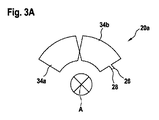
図3A、図3B及び図3Cは、3つのコイル20a,20b,20cに関する、起こり得るコイルレイアウトを概略的に示す。図3Aのコイル20aは、第1の巻線34a及び第2の巻線34bをそれぞれ1つ含む。両方の巻線34a,34bは、同等の大きさであり、又は、同等の面積を取り囲んでいる。両方の巻線は、周方向に沿って互いにずらされている。
3A, 3B and 3C schematically show possible coil layouts for the three
図3Bのコイル20b及び図3Cのコイル20cは、それぞれ2つの第1の巻線34aと、それぞれ1つの第2の巻線34bとを含む。第2の巻線34bは、周方向において第1の巻線34a同士の間に配置されている。第1の巻線34aは、第2の巻線34bとは異なる大きさであり、及び/又は、それぞれ第2の巻線34bよりも小さい。第1の巻線34aによって取り囲まれた面積の合計は、第2の巻線34bによって取り囲まれた面積に一致する。
Each of the
図3A,図3B,図3Cに示されたコイル20a,20b,20cは、回転角度センサにおいて互いに完全に重なり合うように取り付けることができる。この場合、コイル20a,20b,20cの各々には、図2に示されているように、個別の交番電圧V1,V2,V3が供給される。このようにして、それぞれ異なる大きさの面積を取り囲んでいるコイル20b,20cの巻線34a,34bは、コイル20aの巻線34a,34bに対してずらされており、従って、コイル20a,20b,20cの巻線34a,34bは、それぞれ常に部分的にのみ他のコイルの巻線34a,34bによって覆われている。このようにして、3つのコイル20a,20b,20cによって覆われる角度範囲に関して最大の角度分解能を達成することができる。
The
コイル20a,20b,20cの各々は、それぞれの逆向きの複数の巻線を含み、これらの巻線は、第1の方向性を有する第1の巻線34aと、第2の逆向きの方向性を有する第2の巻線34bとに区分することができる。それぞれのコイルの巻線34a,34bは、軸線Aを中心として周方向に順次連続して配置されており、従って、交互の方向性を有する複数の巻線からなる1つのチェーンが生成される。
Each of the
第1の巻線34a及び第2の巻線34bは、それぞれ同等の面積を取り囲んでおり、従って、コイル20a,20b,20cの各々による均一な(干渉)磁場が、それぞれの巻線34a,34bにおいて電流を生成しはするが、個々の電流は、コイル20a,20b,20cにおいて互いに打ち消し合っている。
The first winding 34a and the second winding 34b each surround an equivalent area, so that a uniform (interference) magnetic field by each of the
図4は、誘導エレメント24と、明瞭化の理由から単一のコイル即ち第1のコイル20aとを示す。ただし、以下の説明は、第2のコイル20b及び第3のコイル20cについても該当し得る。図4が示すように誘導エレメント24は、1つの巻線とほぼ同等の大きさであり、即ち、軸線方向から見て又は軸線方向に沿った投影図において、周に沿ってほぼ同等の面積を覆っている。巻線34a,34bの各々が磁場を生成し、今度はこの磁場が誘導エレメント24において渦電流を生成し、今度はこの渦電流が磁場を生成し、そして、この磁場がそれぞれの巻線において電流を生成し、このようにして、それぞれの巻線34a,34bのインダクタンス、ひいてはコイル20a,20b,20cの総インダクタンスが変化する。従って、誘導エレメントを有するロータエレメント14の角度位置に依存して、コイル20a,20b,20cのインダクタンスが変化する。それぞれ異なるコイル20a,20b,20cの第1の巻線34aと第2の巻線34bとが互いにずらされて配置されているので、誘導エレメント24は、それぞれのコイル20a,20b,20cのインダクタンスを追加的にそれぞれ異なるように変化させ、これによって、回転角度センサ10の良好な角度分解能が得られる。
FIG. 4 shows the
図5乃至図7は、図2乃至図4に類似した図を示す。特に断りのない限り、図2乃至図4に関する説明が相応に適用される。 5-7 show views similar to FIGS. 2-4. Unless otherwise noted, the explanations relating to FIGS. 2 to 4 apply accordingly.
図5乃至図7には、回転角度センサ10が示されており、この回転角度センサ10の第1のコイル20a、第2のコイル20b及び第3のコイル20cは、ステータエレメント12を完全に取り囲んでいる。コイル20a,20b,20cは、同等に構成されている。図2と同様に、コイル20a,20b,20cは、ステータエレメント12上で互いにずらされて配置されている。コイル20a,20b,20cのそれぞれ6つの巻線34a,34bは全て、外部干渉場を補償するためにそれぞれ同等の面積を取り囲んでいる。巻線の個数は、6つに限定されているわけではないが、干渉場を補償するために偶数にすべきである。巻線の個数及び開口角度から、センサの周期性が得られる。
FIGS. 5 to 7 show the
図7は、ロータエレメント14上に3つの誘導エレメント24を配置することも可能であることを示す。それぞれほぼ1つの巻線34a,34bを覆っている3つの互いに120°だけずらされた誘導エレメント24によって、120°の一意性範囲において誤差をより良好に補償することができる。この場合、図面をより明瞭にするため、かつ、誘導エレメント24とコイル20a,20b,20cとの相互作用を図示するために、第1のコイル20及び誘導エレメント24のみが一例として図面に図示されている。第2のコイル20b及び第3のコイル20cは、第1のコイル20aに対して回転させられて配置されている。
FIG. 7 shows that it is also possible to arrange three guiding
図8Aは、図2又は図5の回転角度センサのコイル20a,20b,20cに関する導通サイクル36が記載された線図を示す。サイクル36は、3つの同等の長さのステップ38(1ミリ秒の桁数)からなる。一般的に、ステップ38の数は、コイルの個数に等しい。
FIG. 8A shows a diagram describing the
第1のステップ38aの間、第1のコイル20aに交番電圧が供給され、即ち、第1のコイル20aが送信コイル又は励磁コイルとして使用される。残余の2つのコイル(第2のコイル20b及び第3のコイル20c)は導通されず、これらのコイルにおいて生成された交番電圧が特定される。即ち、残余の2つのコイル20b,20cは、受信コイルとして使用される。
During the first step 38a, an alternating voltage is supplied to the
以下のステップにおいては、各コイルの役割が周期的に交代される。第2のステップ38bにおいては、第2のコイル20bが送信コイルとして使用され、第1のコイル20a及び第3のコイル20cが受信コイルとして使用される。第3のステップ38cにおいては、第3のコイル20cが送信コイルとして使用され、第1のコイル20a及び第2のコイル20bが受信コイルとして使用される。その後、次のサイクルが第1のステップ38,38aによって再び開始される。
In the following steps, the role of each coil is periodically changed. In the second step 38b, the
コイル20a,20b,20cを、それぞれ逆向きの巻線34を有する平面コイルとして形成することによって、例えば、第1のコイル20aに交番電圧を印加したときに(誘導エレメント24なしで)巻線34においてそれぞれ異なる符号の交番電磁場が生成される。右回りの巻線34によって取り囲まれた面積と、左回りの巻線34によって取り囲まれた面積とがそれぞれ同等の大きさであるので、場が外部に向かって打ち消され、残余のコイル(即ち、ここでは第2のコイル20b及び第3のコイル20c)において電圧が誘導されることはない。さてここで、誘導エレメント24によって送信コイル表面の一部が遮蔽されると、部分場はもはや互いに打ち消し合わなくなり、他の2つのコイル(第2のコイル20b、第3のコイル20c)において電圧が誘導される。送信コイルと受信コイルとが周期的に交代されることにより、回転角度を逆算することが可能となり、例えば、機械的な誤差に起因するステータエレメント12とロータエレメント14との間の軸線方向における距離の変化を補償することが可能となる。
By forming the
図8Bは、図2又は図5の回転角度センサのコイル20a,20b,20cに関する別の導通サイクル36が記載された線図を示し、ここでは、1つのステップ38につきそれぞれ2つのコイルが導通される。
FIG. 8B shows a diagram illustrating another
第1のステップ38aにおいては、第1のコイル20a及び第2のコイル20bが送信コイルとして使用され、第3のコイル20cが受信コイルとして使用される。第2ステップ38bにおいては、第1のコイル20a及び第3のコイル20cが送信コイルとして使用され、第2のコイル20bが受信コイルとして使用される。第3のステップ38cにおいては、第2のコイル20b及び第3のコイル20cが送信コイルとして使用され、第1のコイル20aが受信コイルとして使用される。
In the first step 38a, the
それぞれ導通される送信コイルには、それぞれ異なる周波数を有する2つの異なる交番電圧を供給することができ、これらの交番電圧は、受信コイルにおいて、回転角度に依存して、両方の周波数を有する2つの成分を有する1つの交番電圧を誘導する。これらの成分は、例えばフーリエ解析によって互いに分離することができ、ここから成分電圧の大きさ及び/又は位相を特定することができる。 Each conducting coil can be supplied with two different alternating voltages, each having a different frequency, which depends on the rotation angle in the receiving coil and has two frequencies with both frequencies. One alternating voltage having a component is induced. These components can be separated from each other, for example by Fourier analysis, from which the magnitude and / or phase of the component voltage can be specified.
最後に、「有する」、「含む」等のような用語が他の要素又はステップを排除しないこと、また、「1つ」のような用語が複数形を排除しないことに留意すべきである。特許請求の範囲における参照符号は、限定するものとして見なすべきではない。 Finally, it should be noted that terms such as “having”, “including”, etc. do not exclude other elements or steps, and terms such as “one” do not exclude a plurality. Any reference signs in the claims should not be construed as limiting.
Claims (9)
少なくとも3つのコイル(20)を有するステータエレメント(12)と、
前記ステータエレメント(12)に対して回転可能に支持されたロータエレメント(14)であって、回転角度に依存して異なる強さで前記少なくとも3つのコイル(20)の各々と誘導結合されるように構成されているロータエレメント(14)と、
前記ロータエレメント(14)と前記ステータエレメント(12)との間の回転角度を特定するための評価ユニット(22)と、
を含む、回転角度センサ(10)において、
前記評価ユニット(22)は、前記コイル(20)のうちのそれぞれ第1の部分に交番電圧が供給されるように、かつ、当該評価ユニットによって残余の部分が非導通となるように、前記コイル(20)に周期的に順次に交番電圧を供給するように構成されており、
前記評価ユニットは、周期的に順次に1つ又は複数の非導通のコイル(20)において、それぞれ誘導された交番電圧の位相及び/又は大きさを特定し、前記誘導された交番電圧の前記位相及び/又は前記大きさに基づいて回転角度を特定するように構成されており、
前記コイル(20)の各々は、少なくとも1つの第1の巻線(34a)及び少なくとも1つの第2の巻線(34b)を有し、
前記少なくとも1つの第1の巻線(34a)と前記少なくとも1つの第2の巻線(34b)とは、それぞれ逆向きに方向付けられており、及び/又は、
1つのコイル(20)の第1の巻線(34a)と第2の巻線(34b)とは、前記ステータエレメント(12)の周方向において交互に配置されており、及び/又は、
前記第1の巻線(34a)によって取り囲まれた面積は、前記第2の巻線(34b)によって取り囲まれた面積と同等である、
ことを特徴とする回転角度センサ(10)。 A rotation angle sensor (10),
A stator element (12) having at least three coils (20);
A rotor element (14) rotatably supported with respect to the stator element (12), wherein the rotor element (14) is inductively coupled to each of the at least three coils (20) with different strengths depending on a rotation angle. A rotor element (14) configured to:
An evaluation unit (22) for specifying a rotation angle between the rotor element (14) and the stator element (12);
In the rotation angle sensor (10) including:
The evaluation unit (22) is configured so that an alternating voltage is supplied to each first part of the coil (20), and the remaining part is made non-conductive by the evaluation unit. (20) is configured to supply alternating voltage periodically and sequentially,
The evaluation unit identifies the phase and / or magnitude of each induced alternating voltage in one or more non-conducting coils (20) sequentially and sequentially, and the phase of the induced alternating voltage And / or is configured to identify a rotation angle based on the magnitude ,
Each of the coils (20) has at least one first winding (34a) and at least one second winding (34b);
The at least one first winding (34a) and the at least one second winding (34b) are each oriented in opposite directions and / or
The first winding (34a) and the second winding (34b) of one coil (20) are alternately arranged in the circumferential direction of the stator element (12) and / or
The area surrounded by the first winding (34a) is equivalent to the area surrounded by the second winding (34b).
The rotation angle sensor (10) characterized by the above-mentioned.
請求項1に記載の回転角度センサ(10)。 Supplying different alternating voltages simultaneously to at least two coils (20) from the first portion of the coils;
The rotation angle sensor (10) according to claim 1.
請求項1又は2に記載の回転角度センサ(10)。 The alternating voltages supplied to the coil (20) from the first portion of the coil have different frequencies, different phases, and / or different magnitudes,
The rotation angle sensor (10) according to claim 1 or 2.
単一のコイル(20)において、誘導された交番電圧を特定し、残余のコイルには交番電圧を供給する、
請求項1乃至3のいずれか一項に記載の回転角度センサ(10)。 Supplying an alternating voltage to only a single coil and identifying the magnitude and / or phase of the induced alternating voltage in each of the remaining coils (20), or
In a single coil (20), identify the induced alternating voltage and supply the alternating voltage to the remaining coils.
The rotation angle sensor (10) according to any one of claims 1 to 3.
請求項1乃至4のいずれか一項に記載の回転角度センサ(10)。 The evaluation unit (22) identifies an axial distance between the stator element (12) and the rotor element (14) from the magnitude and / or the phase of the induced alternating voltage. Configured to,
A rotation angle sensor (10) according to any one of the preceding claims.
前記コイル(20)は、プリント基板(18)の上及び/又は内部に配置されている、
請求項1乃至5のいずれか一項に記載の回転角度センサ(10)。 The coil (20) is a planar coil and / or
The coil (20) is disposed on and / or in the printed circuit board (18),
A rotation angle sensor (10) according to any one of the preceding claims.
前記コイル(20)の各々は、周方向において順次連続した少なくとも2つの巻線(34)を有する、
請求項1乃至6のいずれか一項に記載の回転角度センサ(10)。 The coils (20) are at least partially overlapping each other in the axial direction and / or
Each of the coils (20) has at least two windings (34) that are successively consecutive in the circumferential direction,
A rotation angle sensor (10) according to any one of the preceding claims.
前記コイル(20)の各々は、前記ステータエレメント(12)を完全に取り囲んでいる、
請求項1乃至7のいずれか一項に記載の回転角度センサ(10)。 The coil (20) is arranged in a single angular range of the stator element (12), or
Each of the coils (20) completely surrounds the stator element (12);
Rotation angle sensor as claimed in any one of claims 1 to 7 (10).
前記誘導エレメント(24)は、軸線方向において1つのコイル(20)の単一の巻線(34a,34b)を覆っている、
請求項1乃至8のいずれか一項に記載の回転角度センサ(10)。 The rotor element (14) has at least one guide element (24) arranged in the angular range of the rotor element and / or
The inductive element (24) covers a single winding (34a, 34b) of one coil (20) in the axial direction,
Rotation angle sensor as claimed in any one of claims 1 to 8 (10).
Applications Claiming Priority (3)
| Application Number | Priority Date | Filing Date | Title |
|---|---|---|---|
| DE102015220650.5A DE102015220650A1 (en) | 2015-10-22 | 2015-10-22 | Rotation angle sensor |
| DE102015220650.5 | 2015-10-22 | ||
| PCT/EP2016/074552 WO2017067840A1 (en) | 2015-10-22 | 2016-10-13 | Angular position sensor |
Publications (3)
| Publication Number | Publication Date |
|---|---|
| JP2018531392A JP2018531392A (en) | 2018-10-25 |
| JP2018531392A6 JP2018531392A6 (en) | 2018-12-13 |
| JP6605728B2 true JP6605728B2 (en) | 2019-11-13 |
Family
ID=57130394
Family Applications (1)
| Application Number | Title | Priority Date | Filing Date |
|---|---|---|---|
| JP2018520559A Active JP6605728B2 (en) | 2015-10-22 | 2016-10-13 | Rotation angle sensor |
Country Status (7)
| Country | Link |
|---|---|
| US (1) | US10895475B2 (en) |
| EP (1) | EP3365634B1 (en) |
| JP (1) | JP6605728B2 (en) |
| KR (1) | KR20180070589A (en) |
| CN (1) | CN108351224B (en) |
| DE (1) | DE102015220650A1 (en) |
| WO (1) | WO2017067840A1 (en) |
Families Citing this family (15)
| Publication number | Priority date | Publication date | Assignee | Title |
|---|---|---|---|---|
| DE102016217254B4 (en) * | 2016-09-09 | 2022-02-17 | Robert Bosch Gmbh | Angle of rotation sensor, stator element and rotor element for this |
| DE102016217255A1 (en) * | 2016-09-09 | 2018-03-15 | Robert Bosch Gmbh | Angle of rotation sensor and stator for this |
| WO2019226879A1 (en) * | 2018-05-23 | 2019-11-28 | KSR IP Holdings, LLC | Inductive position sensor assembly |
| CN116412843A (en) * | 2018-05-29 | 2023-07-11 | 京瓷安施电子元件(韦尔讷)有限公司 | Rotational position sensing apparatus and method |
| US11555940B2 (en) | 2018-10-31 | 2023-01-17 | KYOCERA AVX Components (Werne), GmbH | Position sensing apparatus and method |
| EP3767242B1 (en) * | 2019-07-18 | 2022-10-12 | Mecos AG | Determination of axial and rotary positions of a body |
| DE102019213174B9 (en) * | 2019-08-30 | 2023-04-06 | Infineon Technologies Ag | INDUCTIVE ANGLE SENSOR |
| DE102019218399A1 (en) | 2019-11-27 | 2021-05-27 | Infineon Technologies Ag | INDUCTIVE ANGLE SENSOR WITH DISTANCE DETERMINATION |
| EP3919783B1 (en) * | 2020-06-04 | 2023-08-23 | Ningbo Geely Automobile Research & Development Co. Ltd. | A park lock assembly |
| DE102020207225A1 (en) * | 2020-06-09 | 2021-12-09 | Infineon Technologies Ag | INDUCTIVE ANGLE SENSOR WITH STRETCHED COILS |
| DE102020119985A1 (en) | 2020-07-29 | 2022-02-03 | Samson Aktiengesellschaft | Position sensor for determining the position of a valve stem of a control valve |
| US11940342B2 (en) * | 2020-08-18 | 2024-03-26 | Infineon Technologies Ag | Inductive torque sensor for rotating shafts |
| CN112833772B (en) * | 2020-12-31 | 2022-12-09 | 联合汽车电子有限公司 | Angle position sensor, angle measurement system and method and vehicle |
| DE112021007398T5 (en) * | 2021-03-25 | 2024-01-04 | Microchip Technology Incorporated | Detection coil for inductive rotational position measurement and associated devices, systems and methods |
| DE102021131033B3 (en) | 2021-11-26 | 2023-03-02 | Schaeffler Technologies AG & Co. KG | Sensor arrangement and electrical machine |
Family Cites Families (30)
| Publication number | Priority date | Publication date | Assignee | Title |
|---|---|---|---|---|
| DE2725036A1 (en) | 1977-06-03 | 1978-12-14 | Hans Maier | Four stroke rotary IC engine - has vanes sliding radially in cylinder to press on rotor operated by cams |
| IE55855B1 (en) | 1984-10-19 | 1991-01-30 | Kollmorgen Ireland Ltd | Position and speed sensors |
| GB9127112D0 (en) * | 1991-12-20 | 1992-02-19 | Schlumberger Ind Ltd | Smart displacement sensor |
| FR2725036A1 (en) * | 1994-09-22 | 1996-03-29 | Oyo Corp | Emitter for tomographic electromagnetic measurement equipment |
| DE19738839A1 (en) * | 1997-09-05 | 1999-03-11 | Hella Kg Hueck & Co | Inductive angle sensor |
| DE19738836A1 (en) | 1997-09-05 | 1999-03-11 | Hella Kg Hueck & Co | Inductive angle sensor |
| DE60007202T2 (en) * | 1999-03-15 | 2004-11-04 | Goto, Atsutoshi, Fuchu | Inductive position detector |
| DE19920190A1 (en) * | 1999-05-03 | 2000-11-09 | Hella Kg Hueck & Co | Inductive linear sensor and inductive angle sensor |
| DE10022082C1 (en) * | 2000-05-08 | 2001-10-18 | Siedle Horst Gmbh & Co Kg | Inductive measuring transducer for measuring linear or angular displacement has inductive source providing AC magnetic field and sensor device for detecting magnetic field variations |
| AT7524U1 (en) * | 2003-10-31 | 2005-04-25 | Magna Steyr Fahrzeugtechnik Ag | ACTUATOR WITH AN ELECTRIC STATION MOTOR AND CONTROLLABLE FRICTION COUPLING WITH SUCH A |
| US7191759B2 (en) | 2004-04-09 | 2007-03-20 | Ksr Industrial Corporation | Inductive sensor for vehicle electronic throttle control |
| US7276897B2 (en) | 2004-04-09 | 2007-10-02 | Ksr International Co. | Inductive position sensor |
| EP1596495B1 (en) * | 2004-05-12 | 2011-04-27 | ebm-papst St. Georgen GmbH & Co. KG | Method for sensorless operation of an electronically commutated motor, and motor for carrying out such a method |
| US8324892B2 (en) * | 2005-07-26 | 2012-12-04 | Ebm-Papst St. Georgen Gmbh & Co. Kg | Absolute encoder and method for generating an absolute value for a angle of rotation |
| CN2894054Y (en) * | 2006-04-26 | 2007-04-25 | 哈尔滨理工大学 | Magnetosensitive Z element DC brushless electric machine |
| DE102006055409A1 (en) * | 2006-11-22 | 2008-05-29 | Ab Elektronik Gmbh | Inductive sensor for the detection of two coupling elements |
| DE102007015524A1 (en) * | 2007-03-30 | 2008-10-09 | Cherry Gmbh | Method for producing an inductive damping element and inductive eddy current actuating element |
| US8508242B2 (en) * | 2010-01-25 | 2013-08-13 | Ksr Technologies Co. | Inductive position sensor |
| US8519702B2 (en) * | 2010-07-30 | 2013-08-27 | Olympus Ndt Inc. | Orthogonal eddy current probe for multi-directional inspection |
| DE102011007147A1 (en) * | 2011-04-11 | 2012-10-11 | Robert Bosch Gmbh | Electronically commutated electric motor with rotor position detection with interference field compensation |
| US9222804B2 (en) * | 2011-09-02 | 2015-12-29 | Persimmon Technologies Corporation | System and method for position sensing |
| DE102011088725B4 (en) * | 2011-12-15 | 2015-08-06 | Continental Automotive Gmbh | Method and device for determining the torque of an electric motor and motor assembly with an electric motor |
| US20130200884A1 (en) * | 2012-02-08 | 2013-08-08 | Aisan Kogyo Kabushiki Kaisha | Position sensor |
| US9464881B2 (en) * | 2012-08-01 | 2016-10-11 | Silicon Works Co., Ltd. | Displacement sensor, apparatus for detecting displacement, and method thereof |
| US20140131189A1 (en) * | 2012-11-09 | 2014-05-15 | E I Du Pont De Nemours And Company | Combined tangential shear homogenizing and flashing apparatus having rotor/stator gap dimension with uniform and non-uniform regions |
| DE102013204871A1 (en) * | 2013-03-20 | 2014-10-09 | Schaeffler Technologies Gmbh & Co. Kg | Method and angle sensor for contactless measurement of an angle |
| JP2015014549A (en) * | 2013-07-07 | 2015-01-22 | DBLab合同会社 | Rotation angle detection device |
| DE102013221193A1 (en) * | 2013-10-18 | 2015-04-23 | Robert Bosch Gmbh | Sensor arrangement for detecting angles of rotation on a rotating component in a vehicle |
| DE102013221191A1 (en) * | 2013-10-18 | 2015-04-23 | Robert Bosch Gmbh | Sensor arrangement for detecting angles of rotation on a rotating component in a vehicle |
| JP6233641B2 (en) * | 2014-01-31 | 2017-11-22 | パナソニックIpマネジメント株式会社 | Position sensor |
-
2015
- 2015-10-22 DE DE102015220650.5A patent/DE102015220650A1/en active Pending
-
2016
- 2016-10-13 JP JP2018520559A patent/JP6605728B2/en active Active
- 2016-10-13 WO PCT/EP2016/074552 patent/WO2017067840A1/en active Application Filing
- 2016-10-13 CN CN201680061920.1A patent/CN108351224B/en active Active
- 2016-10-13 US US15/769,883 patent/US10895475B2/en active Active
- 2016-10-13 KR KR1020187011259A patent/KR20180070589A/en unknown
- 2016-10-13 EP EP16781126.4A patent/EP3365634B1/en active Active
Also Published As
| Publication number | Publication date |
|---|---|
| WO2017067840A1 (en) | 2017-04-27 |
| CN108351224A (en) | 2018-07-31 |
| EP3365634B1 (en) | 2020-03-25 |
| EP3365634A1 (en) | 2018-08-29 |
| US20180224301A1 (en) | 2018-08-09 |
| US10895475B2 (en) | 2021-01-19 |
| JP2018531392A (en) | 2018-10-25 |
| DE102015220650A1 (en) | 2017-04-27 |
| CN108351224B (en) | 2021-05-11 |
| KR20180070589A (en) | 2018-06-26 |
Similar Documents
| Publication | Publication Date | Title |
|---|---|---|
| JP6605728B2 (en) | Rotation angle sensor | |
| JP2018531392A6 (en) | Rotation angle sensor | |
| JP6605750B2 (en) | Rotation angle sensor | |
| JP6671498B2 (en) | Rotation angle sensor | |
| CN109073420B (en) | Rotation angle sensor | |
| KR101521952B1 (en) | Inductive position sensor | |
| US10907992B2 (en) | Rotational angle sensor | |
| KR101313121B1 (en) | Linear and rotational inductive position sensor | |
| CN109416262B (en) | Rotation angle sensor, stator element and rotor element for the rotation angle sensor | |
| CN110785632A (en) | Rotation angle sensor | |
| CN106996738B (en) | Rotation angle sensor | |
| US10760928B1 (en) | Planar linear inductive position sensor having edge effect compensation | |
| JP6808747B2 (en) | Rotation angle sensor | |
| CN107036635A (en) | Rotary angle transmitter | |
| US20170292857A1 (en) | Sensor Arrangement for the Contactless Sensing of Angles of Rotation on a Rotating Part | |
| CN106996737A (en) | Angular sensor | |
| KR20170127042A (en) | Inductive position sensor | |
| CN107024232B (en) | Rotation angle sensor | |
| US20230273080A1 (en) | Torque Sensing Device and Method | |
| Reddy et al. | Low cost planar coil structure for inductive sensors to measure absolute angular position | |
| CN107036634B (en) | Rotation angle sensor | |
| CN109564111B (en) | Inductive position sensor designed to measure the angular position of a shaft or the like | |
| US20230304831A1 (en) | Detection device for a position sensor and detection system comprising such a detection device | |
| EP4293322A1 (en) | An inductive position sensor for detecting a linear or angular movement of a conductive target | |
| JP5135277B2 (en) | Rotary position detector |
Legal Events
| Date | Code | Title | Description |
|---|---|---|---|
| A521 | Request for written amendment filed |
Free format text: JAPANESE INTERMEDIATE CODE: A523 Effective date: 20180606 |
|
| A621 | Written request for application examination |
Free format text: JAPANESE INTERMEDIATE CODE: A621 Effective date: 20180420 |
|
| A977 | Report on retrieval |
Free format text: JAPANESE INTERMEDIATE CODE: A971007 Effective date: 20190227 |
|
| A131 | Notification of reasons for refusal |
Free format text: JAPANESE INTERMEDIATE CODE: A131 Effective date: 20190318 |
|
| A521 | Request for written amendment filed |
Free format text: JAPANESE INTERMEDIATE CODE: A523 Effective date: 20190617 |
|
| TRDD | Decision of grant or rejection written | ||
| A01 | Written decision to grant a patent or to grant a registration (utility model) |
Free format text: JAPANESE INTERMEDIATE CODE: A01 Effective date: 20191007 |
|
| A61 | First payment of annual fees (during grant procedure) |
Free format text: JAPANESE INTERMEDIATE CODE: A61 Effective date: 20191016 |
|
| R150 | Certificate of patent or registration of utility model |
Ref document number: 6605728 Country of ref document: JP Free format text: JAPANESE INTERMEDIATE CODE: R150 |
|
| R250 | Receipt of annual fees |
Free format text: JAPANESE INTERMEDIATE CODE: R250 |
|
| R250 | Receipt of annual fees |
Free format text: JAPANESE INTERMEDIATE CODE: R250 |