JP6605483B2 - Imaging system and method using pinhole array - Google Patents
Imaging system and method using pinhole array Download PDFInfo
- Publication number
- JP6605483B2 JP6605483B2 JP2016549382A JP2016549382A JP6605483B2 JP 6605483 B2 JP6605483 B2 JP 6605483B2 JP 2016549382 A JP2016549382 A JP 2016549382A JP 2016549382 A JP2016549382 A JP 2016549382A JP 6605483 B2 JP6605483 B2 JP 6605483B2
- Authority
- JP
- Japan
- Prior art keywords
- radiation
- aperture
- image data
- image
- mask
- Prior art date
- Legal status (The legal status is an assumption and is not a legal conclusion. Google has not performed a legal analysis and makes no representation as to the accuracy of the status listed.)
- Expired - Fee Related
Links
- 238000003384 imaging method Methods 0.000 title claims description 89
- 238000000034 method Methods 0.000 title claims description 79
- 230000005855 radiation Effects 0.000 claims description 152
- 230000005540 biological transmission Effects 0.000 claims description 142
- 238000003491 array Methods 0.000 claims description 50
- 238000001914 filtration Methods 0.000 claims description 49
- 238000011084 recovery Methods 0.000 claims description 33
- 238000012545 processing Methods 0.000 claims description 21
- 238000001514 detection method Methods 0.000 claims description 7
- 230000008569 process Effects 0.000 claims description 7
- 230000008859 change Effects 0.000 claims description 5
- 230000000694 effects Effects 0.000 claims description 5
- 230000006872 improvement Effects 0.000 claims description 5
- 230000005670 electromagnetic radiation Effects 0.000 claims description 3
- 238000001228 spectrum Methods 0.000 claims description 3
- 241000239290 Araneae Species 0.000 claims 1
- 239000004615 ingredient Substances 0.000 claims 1
- 238000003530 single readout Methods 0.000 claims 1
- 238000010586 diagram Methods 0.000 description 16
- 230000003287 optical effect Effects 0.000 description 13
- 230000003595 spectral effect Effects 0.000 description 10
- 238000012360 testing method Methods 0.000 description 10
- 238000012546 transfer Methods 0.000 description 6
- 230000004044 response Effects 0.000 description 5
- 238000004088 simulation Methods 0.000 description 5
- 230000000903 blocking effect Effects 0.000 description 3
- 238000005516 engineering process Methods 0.000 description 3
- 239000011295 pitch Substances 0.000 description 3
- 238000012805 post-processing Methods 0.000 description 3
- 238000010276 construction Methods 0.000 description 2
- 238000007796 conventional method Methods 0.000 description 2
- 230000001186 cumulative effect Effects 0.000 description 2
- 238000013461 design Methods 0.000 description 2
- 239000000463 material Substances 0.000 description 2
- 230000035945 sensitivity Effects 0.000 description 2
- GYHNNYVSQQEPJS-OIOBTWANSA-N Gallium-67 Chemical compound [67Ga] GYHNNYVSQQEPJS-OIOBTWANSA-N 0.000 description 1
- 206010028980 Neoplasm Diseases 0.000 description 1
- 206010031252 Osteomyelitis Diseases 0.000 description 1
- 238000009825 accumulation Methods 0.000 description 1
- 238000004458 analytical method Methods 0.000 description 1
- 238000013459 approach Methods 0.000 description 1
- 238000007469 bone scintigraphy Methods 0.000 description 1
- 239000003086 colorant Substances 0.000 description 1
- 230000008602 contraction Effects 0.000 description 1
- 230000007423 decrease Effects 0.000 description 1
- 238000006073 displacement reaction Methods 0.000 description 1
- 229940006110 gallium-67 Drugs 0.000 description 1
- 238000007689 inspection Methods 0.000 description 1
- 230000001788 irregular Effects 0.000 description 1
- 239000011159 matrix material Substances 0.000 description 1
- 238000005259 measurement Methods 0.000 description 1
- 230000007246 mechanism Effects 0.000 description 1
- 239000000203 mixture Substances 0.000 description 1
- 238000012634 optical imaging Methods 0.000 description 1
- 238000007781 pre-processing Methods 0.000 description 1
- 230000001902 propagating effect Effects 0.000 description 1
- 230000009467 reduction Effects 0.000 description 1
- 238000000926 separation method Methods 0.000 description 1
- 230000002123 temporal effect Effects 0.000 description 1
- 238000003325 tomography Methods 0.000 description 1
- 238000000411 transmission spectrum Methods 0.000 description 1
Images


Classifications
-
- H—ELECTRICITY
- H04—ELECTRIC COMMUNICATION TECHNIQUE
- H04N—PICTORIAL COMMUNICATION, e.g. TELEVISION
- H04N13/00—Stereoscopic video systems; Multi-view video systems; Details thereof
- H04N13/10—Processing, recording or transmission of stereoscopic or multi-view image signals
- H04N13/106—Processing image signals
- H04N13/133—Equalising the characteristics of different image components, e.g. their average brightness or colour balance
-
- G—PHYSICS
- G01—MEASURING; TESTING
- G01T—MEASUREMENT OF NUCLEAR OR X-RADIATION
- G01T1/00—Measuring X-radiation, gamma radiation, corpuscular radiation, or cosmic radiation
- G01T1/29—Measurement performed on radiation beams, e.g. position or section of the beam; Measurement of spatial distribution of radiation
- G01T1/2914—Measurement of spatial distribution of radiation
- G01T1/2921—Static instruments for imaging the distribution of radioactivity in one or two dimensions; Radio-isotope cameras
- G01T1/295—Static instruments for imaging the distribution of radioactivity in one or two dimensions; Radio-isotope cameras using coded aperture devices, e.g. Fresnel zone plates
-
- G—PHYSICS
- G02—OPTICS
- G02B—OPTICAL ELEMENTS, SYSTEMS OR APPARATUS
- G02B26/00—Optical devices or arrangements for the control of light using movable or deformable optical elements
- G02B26/06—Optical devices or arrangements for the control of light using movable or deformable optical elements for controlling the phase of light
-
- G—PHYSICS
- G02—OPTICS
- G02B—OPTICAL ELEMENTS, SYSTEMS OR APPARATUS
- G02B27/00—Optical systems or apparatus not provided for by any of the groups G02B1/00 - G02B26/00, G02B30/00
- G02B27/42—Diffraction optics, i.e. systems including a diffractive element being designed for providing a diffractive effect
- G02B27/46—Systems using spatial filters
-
- G—PHYSICS
- G02—OPTICS
- G02B—OPTICAL ELEMENTS, SYSTEMS OR APPARATUS
- G02B30/00—Optical systems or apparatus for producing three-dimensional [3D] effects, e.g. stereoscopic images
- G02B30/20—Optical systems or apparatus for producing three-dimensional [3D] effects, e.g. stereoscopic images by providing first and second parallax images to an observer's left and right eyes
- G02B30/22—Optical systems or apparatus for producing three-dimensional [3D] effects, e.g. stereoscopic images by providing first and second parallax images to an observer's left and right eyes of the stereoscopic type
- G02B30/24—Optical systems or apparatus for producing three-dimensional [3D] effects, e.g. stereoscopic images by providing first and second parallax images to an observer's left and right eyes of the stereoscopic type involving temporal multiplexing, e.g. using sequentially activated left and right shutters
-
- G—PHYSICS
- G02—OPTICS
- G02B—OPTICAL ELEMENTS, SYSTEMS OR APPARATUS
- G02B5/00—Optical elements other than lenses
- G02B5/20—Filters
- G02B5/201—Filters in the form of arrays
-
- G—PHYSICS
- G06—COMPUTING; CALCULATING OR COUNTING
- G06T—IMAGE DATA PROCESSING OR GENERATION, IN GENERAL
- G06T5/00—Image enhancement or restoration
-
- G06T5/80—
-
- H—ELECTRICITY
- H04—ELECTRIC COMMUNICATION TECHNIQUE
- H04N—PICTORIAL COMMUNICATION, e.g. TELEVISION
- H04N13/00—Stereoscopic video systems; Multi-view video systems; Details thereof
- H04N13/10—Processing, recording or transmission of stereoscopic or multi-view image signals
- H04N13/106—Processing image signals
- H04N13/122—Improving the 3D impression of stereoscopic images by modifying image signal contents, e.g. by filtering or adding monoscopic depth cues
-
- H—ELECTRICITY
- H04—ELECTRIC COMMUNICATION TECHNIQUE
- H04N—PICTORIAL COMMUNICATION, e.g. TELEVISION
- H04N13/00—Stereoscopic video systems; Multi-view video systems; Details thereof
- H04N13/20—Image signal generators
- H04N13/204—Image signal generators using stereoscopic image cameras
- H04N13/207—Image signal generators using stereoscopic image cameras using a single 2D image sensor
- H04N13/211—Image signal generators using stereoscopic image cameras using a single 2D image sensor using temporal multiplexing
-
- H—ELECTRICITY
- H04—ELECTRIC COMMUNICATION TECHNIQUE
- H04N—PICTORIAL COMMUNICATION, e.g. TELEVISION
- H04N13/00—Stereoscopic video systems; Multi-view video systems; Details thereof
- H04N13/20—Image signal generators
- H04N13/204—Image signal generators using stereoscopic image cameras
- H04N13/207—Image signal generators using stereoscopic image cameras using a single 2D image sensor
- H04N13/218—Image signal generators using stereoscopic image cameras using a single 2D image sensor using spatial multiplexing
-
- G—PHYSICS
- G02—OPTICS
- G02B—OPTICAL ELEMENTS, SYSTEMS OR APPARATUS
- G02B2207/00—Coding scheme for general features or characteristics of optical elements and systems of subclass G02B, but not including elements and systems which would be classified in G02B6/00 and subgroups
- G02B2207/129—Coded aperture imaging
-
- G—PHYSICS
- G21—NUCLEAR PHYSICS; NUCLEAR ENGINEERING
- G21K—TECHNIQUES FOR HANDLING PARTICLES OR IONISING RADIATION NOT OTHERWISE PROVIDED FOR; IRRADIATION DEVICES; GAMMA RAY OR X-RAY MICROSCOPES
- G21K1/00—Arrangements for handling particles or ionising radiation, e.g. focusing or moderating
- G21K1/02—Arrangements for handling particles or ionising radiation, e.g. focusing or moderating using diaphragms, collimators
- G21K1/04—Arrangements for handling particles or ionising radiation, e.g. focusing or moderating using diaphragms, collimators using variable diaphragms, shutters, choppers
-
- H—ELECTRICITY
- H04—ELECTRIC COMMUNICATION TECHNIQUE
- H04N—PICTORIAL COMMUNICATION, e.g. TELEVISION
- H04N13/00—Stereoscopic video systems; Multi-view video systems; Details thereof
- H04N2013/0074—Stereoscopic image analysis
- H04N2013/0081—Depth or disparity estimation from stereoscopic image signals
-
- H—ELECTRICITY
- H04—ELECTRIC COMMUNICATION TECHNIQUE
- H04N—PICTORIAL COMMUNICATION, e.g. TELEVISION
- H04N13/00—Stereoscopic video systems; Multi-view video systems; Details thereof
- H04N2013/0074—Stereoscopic image analysis
- H04N2013/0092—Image segmentation from stereoscopic image signals
Description
本発明は、放射線撮像の分野であり、ピンホールアレイを用いた撮像技術に関する。 The present invention is in the field of radiation imaging, and relates to an imaging technique using a pinhole array.
ここに開示した主題の背景として関連すると考えられる引用文献は以下の通りである。
[1]R.A.Vogel,D.Kirch,M.Lefree,and P.Steele,“A New Method of Multiplanar Emission Tomography Using a Seven Pinhole Collimator and an Auger Scintillation Camera,”J.Nucl.Med.19(6),648−654(1978).
[2]N.U.Schramm,G.Ebel,U.Engeland,T.Schurrat,M.Behe and T.M.Behr,“High−Resolution SPECT Using Multipinhole Collimation,”IEEE Trans.Nucl.Sci.50(3),315−320(2003).
[3]R.H.Dicke,“Scatter−hole cameras for x−rays and gamma rays,”Astrophys.J.153,L101−L106(1968).
[4]L.T.Chang,B.Macdonald,V.Perez−Mendez, L.Shiraishi,“Coded Aperture Imaging of Gamma−Rays Using Multiple Pinhole Arrays and Multiwire Proportional Chamber Detector,”IEEE Trans.Nucl.Sci.NS−22,374−378(1975).
[5]E.E.Fenimore and T.M.Cannon,“Coded aperture imaging:predicted performance of uniformly redundant arrays,”Appl.Opt.17(2),3562−3570(1978).
[6]Mu Z,Hong B,Li S Liu YH,“A noval three−dimensional image reconstruction method for near−field coded aperture single photon emission computerized tomography”.Med Phys.2009:36;1533−1542.
[7]Chen YW,Yamanaka M,Miyanaga N,Yamanaka T,Nakai S,Yamanaka C,“Three−dimensional reconstructions of laser−irradiated targets using URA coded aperture cameras”.Opt Commun.1989:71;249−255.
[8]Koral KF,Rogers WL,Knoll GF,“Digital tomographic imaging with time−modulated pseudorandom coded aperture and anger camera”.J Nucl Med.1974:16;402−413
References that are considered relevant as background to the subject matter disclosed herein are:
[1] R.M. A. Vogel, D.M. Kirch, M.M. Lefree, and P.M. Steele, “A New Method of Multiplanar Emission Tomography Using a Seven Pinhole Collimator and an Auger Scintillation Camera,” J. Nucl. Med. 19 (6), 648-654 (1978).
[2] N. U. Schramm, G.M. Ebel, U .; Engeland, T.W. Schurrat, M .; Behe and T.W. M.M. Behr, “High-Resolution SPECT Using Multipinhole Collimation,” IEEE Trans. Nucl. Sci. 50 (3), 315-320 (2003).
[3] R.M. H. Dicke, “Scatter-hole cameras for x-rays and gamma rays,” Astrophys. J. et al. 153, L101-L106 (1968).
[4] L.M. T.A. Chang, B.M. Macdonald, V.M. Perez-Mendez, L.M. Shirai, “Coded Aperture Imaging of Gamma-Rays Using Multiple Pinhole Arrays and Multiwire Proportional Chamber Detector,” IEEE Trans. Nucl. Sci. NS-22, 374-378 (1975).
[5] E.E. E. Fenimore and T. M.M. Cannon, “Coded Aperture Imaging: Predicted Performance of Uniform Redundant Arrays,” Appl. Opt. 17 (2), 3562-3570 (1978).
[6] Mu Z, Hong B, Li S Liu YH, “A novel three-dimensional image re- method construction for near-field coded aper- timation empirical singe- mentation phne thomp emis tom te s s s s s”. Med Phys. 2009: 36; 1533-1542.
[7] Chen YW, Yamanaka M, Miyanaka N, Yamanaka T, Nakai S, Yamanaka C, “Three-dimensional restructurings of laser-irradiated irradiated weights. Opt Commun. 1989: 71; 249-255.
[8] Koral KF, Rogers WL, Knoll GF, “Digital tomographic imaging with time-modulated pseudoand coded approach and angel camera”. J Nucl Med. 1974: 16; 402-413
上述の引用文献の確認は、ここに開示した主題の特許性に関連する意味を暗示するものではない。 Confirmation of the above cited references does not imply any implications relating to the patentability of the subject matter disclosed herein.
ピンホール光学を撮像技術に使用することは長年知られている。光線はマスクの一方の側にある対象領域から伝搬し、マスクの小さなピンホールを通ってマスクの他方の側に広がり、対象領域の画像の生成に使用することができる。 The use of pinhole optics for imaging technology has been known for many years. Rays propagate from the target area on one side of the mask, spread through the small pinhole of the mask to the other side of the mask, and can be used to generate an image of the target area.
ピンホール光学は、リニア歪の低減、実質的に無限の焦点深度と、広角視野の提供といった、レンズ系の一般的使用を超える様々な利点を提供できる。さらに、ピンホール撮像は、X線、ガンマ線、及び基本的な波動現象あるいは微粒子様現象といった、非光学的電磁波の周波数に利用できる。 Pinhole optics can provide various advantages over the general use of lens systems, such as reducing linear distortion, providing a virtually infinite depth of focus, and providing a wide-angle field of view. Furthermore, pinhole imaging can be used for non-optical electromagnetic frequencies such as X-rays, gamma rays, and fundamental wave or fine particle-like phenomena.
ピンホール撮像の特性は、一般的に、ピンホールの特に断面寸法(直径)に依存する。大きなピンホールでは、結果としての画像は通常ピンホールの幾何学的影である均一なディスクの形である。非常に小さなピンホールでは、結果としての画像はフレネルパターン又はフラウンホーファー解析パターンである。中間サイズのピンホールは、光景(シーン)の撮像を提供する。最適なピンホール径は、大きなピンホールの大きなスポット画像と、小さなピンホールサイズの広い回析パターンとの妥協点として決めることができる。 The characteristics of pinhole imaging generally depend on the pinhole, particularly the cross-sectional dimension (diameter). For large pinholes, the resulting image is usually in the form of a uniform disk that is the geometric shadow of the pinhole. For very small pinholes, the resulting image is a Fresnel pattern or a Fraunhofer analysis pattern. Medium size pinholes provide imaging of the scene. The optimum pinhole diameter can be determined as a compromise between a large spot image of a large pinhole and a wide diffraction pattern with a small pinhole size.
ピンホールサイズの画像生成範囲内には、画像解像度と光強度間のトレードオフがある。より大きいピンホールは比較的高い放射強度を伝送する、すなわち、時間当たりのフォトンの数が多いが、画像解像度が低くなる。一方、より小さいピンホールは、画像解像度は高いが、放射強度は低くなる。この結果、より暗い画像となる、及び/又は、露出時間がより長くなる。したがって、ピンホールのサイズは、画像解像度、コントラスト、輝度、露出時間、信号対ノイズ比に影響する。 Within the pinhole size image generation range, there is a trade-off between image resolution and light intensity. Larger pinholes transmit relatively high radiant intensity, i.e., more photons per hour, but lower image resolution. On the other hand, smaller pinholes have higher image resolution but lower radiation intensity. This results in a darker image and / or a longer exposure time. Therefore, the size of the pinhole affects the image resolution, contrast, brightness, exposure time, and signal to noise ratio.
複数のピンホールを使用して撮像技術を改善する目的で、輝度及び/又は解像度を改善するいくつかの技術が知られている。 Several techniques are known to improve brightness and / or resolution in order to improve imaging techniques using multiple pinholes.
国際公開第2010/119,447号は、多数の感光ピクセルを具える所定の光検出面に使用する光学システムについて記載している。この光学システムは、複数のスペースを空けて配置された光透過領域によって形成され、複数の感光ピクセルによって構成された所定の光透過パターンを規定する光学窓を具える。この複数のスペースを空けて配置された光透過領域の構成は、複数の感光ピクセルに対してこの領域の不規則な配置を規定している。この不規則な配置を有する光学窓は、撮像するシーンからの様々な方向からくる光ビームを回収して、各感光ピクセルの上に、異なる方向から回収された光ビームに対応して区別できる光強度によって形成された光成分を向けるように構成されており、これによって、光検出面上に重なった、異なる方向から回収した光ビームに応じた、空間的に区別された光強度パターンを提供している。
WO 2010 / 119,447 describes an optical system for use with a given light detection surface comprising a large number of photosensitive pixels. The optical system includes an optical window defined by a plurality of light-transmitting regions arranged with a plurality of spaces and defining a predetermined light transmission pattern constituted by a plurality of photosensitive pixels. The configuration of the light transmissive region arranged with a plurality of spaces defines an irregular arrangement of the region with respect to the plurality of photosensitive pixels. This irregularly arranged optical window collects light beams coming from various directions from the scene being imaged and can be distinguished on each photosensitive pixel corresponding to the light beams collected from different directions. It is configured to direct the light component formed by intensity, thereby providing a spatially distinct light intensity pattern depending on the light beam collected from different directions superimposed on the light detection surface. ing.
米国特許第6,545,265B号は、共焦点画像対を混合する方法と、平行共焦点画像高速発生用の様々な構成と、そのリアルタイムでの組み合わせを記載している。この方法は、共焦点画像のコントラストと解像度を改良するのに使用される。提言されている構成は、多種多様なアプリケーション用、特に、材料検査用にリアルタイムで高解像度の画像を生成する、平行共焦点シングルビーム法又はダブルビーム法において画像を混合する方法の有意なアプリケーションにいくつかの可能性を示唆している。二以上の共焦点画像を組み合わせると、混合画像における対象の優れた構造の解像度が得られる。これに対して、方位分解能と深さ分解能は、位相物体でもありうる検査すべき対象物の混合画像において改善される。さらに、この方法によれば、検査すべき対象物の非常に解像度が高い三次元デジタル画像を生成できる。 US Pat. No. 6,545,265B describes a method for mixing confocal image pairs, various configurations for fast generation of parallel confocal images, and combinations in real time. This method is used to improve the contrast and resolution of confocal images. The proposed configuration is useful for a wide variety of applications, especially for applications that mix images in parallel confocal single beam or double beam methods that produce high-resolution images in real time for material inspection. It suggests several possibilities. Combining two or more confocal images provides excellent structural resolution of the object in the mixed image. In contrast, the azimuth and depth resolutions are improved in a mixed image of the object to be examined, which can also be a phase object. Furthermore, according to this method, it is possible to generate a three-dimensional digital image having a very high resolution of the object to be inspected.
米国特許出願公開第2006/279,845号は、隣接するレンズ間でピッチが異なる二群のマイクロレンズサブアッセンブリからなる、一のマイクロレンズアレイで構成された光学システムを記載している。サブアッセンブリのピッチ間の比は、光学システムのパラメータ間の所定の関係によって決まり、第1のサブアッセンブリのマイクロレンズが、共通の中間面に並んで配置された複数の独立した中間画像を作る。共通の中間平面は、第2のサブアッセンブリのマイクロレンズによって、互いの上に割り込んだ複数の同じでかつ正確に登録された画像の形で最終画像平面へ転送される。これは、上述のピッチ間の比率によって達成される。 U.S. Patent Application Publication No. 2006 / 279,845 describes an optical system comprised of a single microlens array consisting of two groups of microlens subassemblies with different pitches between adjacent lenses. The ratio between the pitches of the subassemblies is determined by a predetermined relationship between the parameters of the optical system, creating a plurality of independent intermediate images in which the microlenses of the first subassembly are arranged side by side on a common intermediate plane. The common intermediate plane is transferred by the second sub-assembly microlenses to the final image plane in the form of a plurality of identical and correctly registered images interrupted on top of each other. This is achieved by the ratio between the pitches described above.
この分野では、一またはそれ以上のピンホールアレイを用いた高解像度の撮像を可能にする新しい技術が必要とされている。本発明の技術によれば、各アレイが所定の異なるピンホール配置を有する、二またはそれ以上のピンホールアレイを用いて対象となる領域の高品質画像を生成することができる。この二またはそれ以上のアレイにおけるピンホール配置は、二またはそれ以上のピンホールアレイのそれぞれを通る二またはそれ以上の画像取得ステップ間に、放射回収の所望のトータル有効透過関数を提供するように選択される。 There is a need in the art for new technologies that enable high resolution imaging using one or more pinhole arrays. According to the technique of the present invention, it is possible to generate a high-quality image of a region of interest using two or more pinhole arrays, each array having a predetermined different pinhole arrangement. This pinhole arrangement in the two or more arrays is such that it provides the desired total effective transmission function of radiation recovery between two or more image acquisition steps through each of the two or more pinhole arrays. Selected.
一般的に、ピンホールベースの撮像は、画像解像度(光学解像度)と、強度(エネルギィ)との間の選択が必要であり、従来の方法によれば、このファクタの一方を改良すると他方のコスト高を避けることができない。しかしながら、本発明の技術によれば、光学的放射並びに非光学的放射による撮像用に、ピンホール撮像の利点を利用できる一方で、達成される解像度を低下させることなくより大きな入力強度を提供することができる。このことは、空間的及び画像マルチプレキシングと時間的画像マルチプレキシングを組み合わせたピンホール撮像の概念を用いて本発明の技術で達成され、効率の良い撮像を提供し、高品質な画像データの再構築を可能とする。 In general, pinhole-based imaging requires a choice between image resolution (optical resolution) and intensity (energy), and according to conventional methods, improving one of these factors reduces the cost of the other. Inevitable high. However, according to the technique of the present invention, the advantages of pinhole imaging can be utilized for imaging with optical as well as non-optical radiation while providing greater input intensity without reducing the resolution achieved. be able to. This is achieved with the technique of the present invention using the concept of pinhole imaging that combines spatial and image multiplexing and temporal image multiplexing to provide efficient imaging and re-create high quality image data. Enable construction.
本発明の技術によれば、対象領域から伝搬してくる入力放射(光学的又は非光学的)が、所定のトータル露出時間用の画像システムによって回収される。この入力放射は、二またはそれ以上のピンホール(開口)アレイセットを通って、対応する時間、順次撮像される。各ピンホールアレイは、放射線を透過させる形状を有する所定の寸法の一またはそれ以上のピンホールのあらかじめ選択された配置を有する放射ブロック面によって形成されたマスクである。
According to the technique of the present invention, input radiation (optical or non-optical) propagating from the target area is collected by an imaging system for a predetermined total exposure time. The input radiation passes through the two or more pin holes (openings) array set, the corresponding time are sequentially captured. Each pinhole array is a mask formed by a radiation blocking surface having a preselected arrangement of one or more pinholes of a predetermined size having a shape that transmits radiation.
ピンホールアレイセットは、二またはそれ以上のピンホールアレイ(例えば、所定数のピンホールを有するマスク)を具え、各アレイが、選択した所望の寸法の幾何学的形状の所定数のピンホール配置を具える。各アレイについてピンホールで回収した放射により画像平面(検出器の)上に複数の重なり合った画像となる。本発明の技術によれば、多数のこのような重なり合った画像が所定の露出時間に回収される。したがって、連続する二またはそれ以上の入力画像データピースが、二またはそれ以上のピンホールアレイによる入力放射の回収を介して生成される。各画像データピースは、選択したピンホールアレイと選択した回収(露出)時間に対応する。この画像データピースは、次いで、各アレイにおけるピンホールの配置と、トータル有効透過関数を規定する露出時間に基づいて処理され、対象領域を表す回復画像データを規定する。
A pinhole array set comprises two or more pinhole arrays (eg, a mask having a predetermined number of pinholes), each array having a predetermined number of pinhole arrangements of a geometric shape of a desired size selected. With The radiation collected at the pinhole for each array results in a plurality of overlapping images on the image plane (of the detector). In accordance with the technique of the present invention, a number of such overlapping images are collected at a predetermined exposure time. Thus, two or more consecutive input image data pieces are generated through the collection of input radiation by two or more pinhole arrays. Each image data piece corresponds to a selected pinhole array and a selected collection (exposure) time. This image data piece is then processed based on the placement of pinholes in each array and the exposure time defining the total effective transmission function to define recovered image data representing the region of interest.
一般的に、二またはそれ以上のピンホールアレイを通る放射線透過は、異なるピンホールを通過する放射線部分の干渉によって情報の喪失を生む。これは、ピンホールアレイに関連して、ゼロ伝送を伴う一またはそれ以上の空間周波数を有する空間周波数透過スペクトルにみられる。本発明の技術は、二またはそれ以上のピンホールアレイの一方が、所定の空間周波数についてゼロ又は低い透過率を有していれば、アレイセットの一またはそれ以上の他方のアレイがこの空間周波数においてより高い透過率を有し、トータルでの有効透過関数が、所望の解像度制限内ですべての空間周波数について非空透過を提供するように選択された二またはそれ以上のピンホールアレイセットを使用している。したがって、開口アレイの正しい選択は、このセットの累積透過が所望の解像度限界内で非空値を伴う有効透過関数を形成するようになされる。開口アレイセットのこの選択は、また、入力画像データの比較的簡単で効率の良い後処理を提供し、対象領域の回復画像を生成する。この処理は、トータル有効透過関数と画像構築用のその逆作用についてのデータを使用する。 In general, radiation transmission through two or more pinhole arrays results in loss of information due to interference of radiation portions that pass through different pinholes. This can be seen in the spatial frequency transmission spectrum with one or more spatial frequencies with zero transmission in connection with the pinhole array. The technique of the present invention allows one or more other arrays in the array set to have this spatial frequency if one of the two or more pinhole arrays has zero or low transmission for a given spatial frequency. Use two or more pinhole array sets that have higher transmission in and the total effective transmission function is selected to provide non-empty transmission for all spatial frequencies within the desired resolution limit is doing. Thus, the correct choice of aperture array is made such that this set of cumulative transmissions forms an effective transmission function with non-null values within the desired resolution limits. This selection of aperture array set also provides a relatively simple and efficient post-processing of the input image data and produces a restored image of the target area. This process uses data about the total effective transmission function and its inverse for image construction.
このように、本発明の一つの広い態様によれば、対象領域を撮像する方法が提供されている。この方法は:
(a)対象領域から選択した複数の所定数開口アレイセットを通る入力放射を回収するステップであって、各アレイが所定の開口配置を有し、回収時間ピリオドの間入力放射を回収し、選択された回収アレイセットと対応する回収時間ピリオドが、放射線回収のトータル有効透過関数を規定している、ステップと;
(b)回収した入力放射から画像データを生成するステップであって、この画像データが、各開口アレイを通って回収された入力放射に対応する所定数の画像データピースを含む、ステップと;
(c)この画像データピースを、放射線回収のトータル有効透過関数を用いて処理し、対象領域の回復画像を決定するステップと;
を具える。
Thus, according to one broad aspect of the present invention, a method for imaging a target region is provided. This method is:
(A) recovering input radiation through a plurality of a predetermined number of aperture array sets selected from a target area, each array having a predetermined aperture arrangement, and recovering and selecting input radiation during a recovery time period The collected collection array set and the corresponding collection time period define the total effective transmission function for radiation collection; and
(B) generating image data from the collected input radiation, the image data including a predetermined number of image data pieces corresponding to the input radiation collected through each aperture array;
(C) processing the image data piece using a total effective transmission function of radiation recovery to determine a restored image of the target area;
With
開口アレイセットは、好ましくは、トータル有効透過関数が、所定の最大空間周波数より低い空間周波数に非空透過を提供するように選択される。一般的に、この最大空間周波数は、最小開口サイズによって決まる。最大空間周波数を規定する最小開口サイズは、画像検出の幾何学的解像度に応じて選択することができる。 The aperture array set is preferably selected such that the total effective transmission function provides non-empty transmission at spatial frequencies below a predetermined maximum spatial frequency. In general, this maximum spatial frequency is determined by the minimum aperture size. The minimum aperture size that defines the maximum spatial frequency can be selected depending on the geometric resolution of image detection.
いくつかの実施例によれば、選択した開口アレイの対応する回収時間ピリオドを選択して、選択した空間周波数についての透過度を最適にする。 According to some embodiments, the corresponding collection time period of the selected aperture array is selected to optimize the transmission for the selected spatial frequency.
いくつかの実施例によれば、この方法は、さらに、開口アレイの全回収時間ピリオドについて単一の読み出しモードを用いて画像データピースを検出するステップを具え、これによって、画像データを一体化して一回のスキャン時間に画像データを形成しつつも、異なる開口アレイを選択的に使用できるようにする。代替的に、専用の読み出しセッションを各開口アレイに使用して、結果としての画像データピースを数字として合算するようにしてもよい。
According to some embodiments, the method further for total recovery time period of the aperture array comprises the step of detecting the image data pieces by using a single read mode, thereby integrating the image data Thus, it is possible to selectively use different aperture arrays while forming image data in one scan time. Alternatively, a dedicated readout session may be used for each aperture array so that the resulting image data pieces are summed as numbers.
対象領域の画像を回復するための画像データピースの処理は:画像データピースの強度マップの和を受信する、あるいは決定するステップと、トータル有効透過関数によって生じる歪効果の反転を利用するステップを具え、これによって回復画像データを生成する。この処理は、有効透過関数のウイナーデコンボリューションを用いるステップを具える。 The processing of the image data piece to recover the image of the region of interest comprises the steps of: receiving or determining the sum of the intensity map of the image data piece and utilizing the reversal of the distortion effect caused by the total effective transmission function. Thereby, the recovery image data is generated. This process comprises the step of using a Wiener deconvolution of the effective transmission function.
いくつかの実施例では、回復画像データを空間周波数ドメインで決定できる。 In some embodiments, the recovered image data can be determined in the spatial frequency domain.
なお、本発明の方法は、赤外線放射、可視光、紫外線放射、X線放射、及びガンマ線放射のスペクトルの少なくとも一つにおける電磁放射である入力放射と共に使用することができる。 It should be noted that the method of the present invention can be used with input radiation that is electromagnetic radiation in at least one of the spectrum of infrared radiation, visible light, ultraviolet radiation, X-ray radiation, and gamma radiation.
いくつかの実施例によれば、回復画像データを決定する画像データピースの処理がさらに、それぞれが開口アレイセットから異なる距離に位置する対象領域の対物面からの入力放射の回収に、対応する二つの異なる深さ解像有効透過関数セットを提供するステップと;各深さ解像有効透過関数について、各対物面に対応する部分的に回復した画像データピースを決定するステップと;対象領域の三次元回復画像を表すデータを生成するステップと;を具える。この少なくとも二つの異なる深さ解像有効透過関数は、選択した対物面から撮像する倍率を変化させることによる仮想開口配置に基づいて決めることができる。 According to some embodiments, the processing of the image data pieces to determine the recovered image data further corresponds to a recovery of input radiation from the object plane of the target area, each located at a different distance from the aperture array set. Providing two different depth resolution effective transmission function sets; determining, for each depth resolution effective transmission function, a partially recovered image data piece corresponding to each object plane; Generating data representing the original recovered image. The at least two different depth resolution effective transmission functions can be determined based on the virtual aperture arrangement by changing the magnification for imaging from the selected object plane.
いくつかの実施例によれば、開口アレイセットとその対応する開口配置は、所望の放射強度改善(RII)因子に従って選択して、画像輝度を改善した対象領域の撮像を提供することができる。 According to some embodiments, an aperture array set and its corresponding aperture arrangement can be selected according to a desired radiant intensity improvement (RII) factor to provide imaging of a region of interest with improved image brightness.
いくつかの実施例では、複数の所定数の開口アレイセットと、その対応する開口配置の選択が:撮像用の所望の解像度と対応する最小開口寸法を決定するステップと;各開口の形状と角度を決定するステップと;開口数を決めて所望の撮像輝度を提供するステップと;アレイの所定数を決定するステップと;各アレイにおける開口配置を決定して、開口アレイセットの非空トータル有効透過関数を提供するステップと、を具える。開口配置の決定は:第1アレイの開口配置を決定するステップと;対応する有効透過関数を決定するステップと;その有効透過関数が所定のしきい値より低い透過を提供する空間周波数を同定するステップと;同定した空間周波数における一またはそれ以上の追加開口配置の透過が所定のしきい値を超えるように、一またはそれ以上の追加開口配置を決定するステップと;を具える。 In some embodiments, selection of a plurality of predetermined number of aperture array sets and their corresponding aperture arrangements: determining a desired resolution for imaging and a corresponding minimum aperture size; shape and angle of each aperture Determining a numerical aperture to provide a desired imaging brightness; determining a predetermined number of arrays; determining an aperture arrangement in each array to provide a non-empty total effective transmission of the aperture array set Providing a function. Determining the aperture arrangement: determining the aperture arrangement of the first array; determining the corresponding effective transmission function; identifying a spatial frequency at which the effective transmission function provides transmission below a predetermined threshold Determining one or more additional aperture configurations such that the transmission of the one or more additional aperture configurations at the identified spatial frequency exceeds a predetermined threshold.
本発明のもう一つの広い態様によれば、撮像システムが提供されており、このシステムは:
(a)回収されている入力放射の空間フィルタリング用放射回収面を規定するマスクであって、複数の開口を具え、マスクの所定数の空間フィルタリングパターンを選択するように構成され作用し、各フィルタリングパターンが回収面の開口の所定の配置によって形成される、マスクと;
(b)フィルタリングコントローラモジュールと;画像取得モジュールと画像処理モジュールとを具える制御ユニットであって、フィルタリングモジュールが選択された露出時間ピリオドの間に様々なフィルタリングパターンによって入力放射を選択的に回収するようにマスクを作動させるように構成されており;画像取得モジュールが選択した露出時間ピリオドの間のそれぞれフィルタリングパターンを介する入力放射の回収に応じた画像データピースを受け取るように構成されており;画像処理モジュールが、この画像データピースを受け取って処理し、マスクを介して放射回収のトータル有効透過関数を表すデータを利用するとともに、入力放射が回収されている対象領域の回復画像データを決定するように構成されている、制御ユニットと;
を具える。
According to another broad aspect of the present invention, an imaging system is provided, the system comprising:
(A) a mask defining a radiation collection surface for spatial filtering of the input radiation being collected, comprising a plurality of apertures, configured and acting to select a predetermined number of spatial filtering patterns of the mask, each filtering A mask formed by a predetermined arrangement of openings in the collection surface;
(B) a filtering controller module; a control unit comprising an image acquisition module and an image processing module, wherein the filtering module selectively collects input radiation by various filtering patterns during a selected exposure time period The image acquisition module is configured to receive image data pieces in response to collection of input radiation through respective filtering patterns during a selected exposure time period; A processing module receives and processes this image data piece, uses the data representing the total effective transmission function of radiation recovery through a mask, and determines the recovered image data of the target area from which the input radiation is being recovered. The control unit Door and;
With
マスクの選択した複数の所定数の空間フィルタリングパターンは、所望のあらかじめ決められた最大空間周波数より小さい空間周波数について非空透過を伴う有効透過関数を提供するようあらかじめ選択することができる。 A plurality of predetermined numbers of spatial filtering patterns selected by the mask can be preselected to provide an effective transmission function with non-empty transmission for spatial frequencies that are less than a desired predetermined maximum spatial frequency.
一般的に、マスクは、交換可能なマスクとして構成することができ、これは複数の所定数の空間フィルタリングパターンを具えており、マスクの放射回収面に選択した空間フィルタリングパターンを選択的に配置するようにできる。例えば、マスクは、それぞれが対向するフィルタリングパターンを規定している二またはそれ以上の開口アレイを具える機械的ホイールとして構成できる。追加であるいは代替的に、マスクは、放射透過モジュレータとして構成してもよく、フィルタリングパターンを電気的に変化させるように構成できる。 In general, the mask can be configured as a replaceable mask, which comprises a plurality of a predetermined number of spatial filtering patterns and selectively places the selected spatial filtering pattern on the radiation collection surface of the mask. You can For example, the mask can be configured as a mechanical wheel with two or more aperture arrays each defining an opposing filtering pattern. Additionally or alternatively, the mask may be configured as a radiation transmission modulator and can be configured to electrically change the filtering pattern.
いくつかの実施例によれば、マスクは所定数の空間フィルタリングパターンに対応する多重構成の開口を具えていてもよく、この開口の多重構成は、様々なフィルタリングパターンに対応する開口群を具えており、各開口群が、撮像用のトータル波長レンジの一部である所定の波長レンジを透過するように構成された波長選択フィルタを具えていてもよい。 According to some embodiments, the mask may include multiple configurations of apertures corresponding to a predetermined number of spatial filtering patterns, the multiple configurations of apertures including groups of apertures corresponding to various filtering patterns. Each aperture group may include a wavelength selection filter configured to transmit a predetermined wavelength range that is a part of the total wavelength range for imaging.
プロセッサユニットは、さらに、所望の解像度と輝度に関するデータを含む入力データに応答して、非空有効透過関数を有する対応するフィルタリングパターンセットを決定するように構成された選択モジュールセットを具えていてもよい。 The processor unit may further comprise a selection module set configured to determine a corresponding filtering pattern set having a non-empty effective transmission function in response to input data including data relating to the desired resolution and brightness. Good.
いくつかの実施例によれば、プロセッサユニットはさらに、このフィルタリングパターンセットの開口配列によって深さを改善した有効透過関数を決定するように構成した深さ解像度前処理モジュールを具えていてもよい。画像処理モジュールは、複数の回復した深さ解像画像データピースを決定するよう構成され作動する。各深さ解像回復画像データピースは、対応する深さ解像有効透過関数に応じて対物面に対応しており、これによって、対象領域についての三次元情報を提供している。 According to some embodiments, the processor unit may further comprise a depth resolution preprocessing module configured to determine an effective transmission function with improved depth by the aperture arrangement of the filtering pattern set. The image processing module is configured and operative to determine a plurality of recovered depth resolution image data pieces. Each depth resolution recovered image data piece corresponds to the object plane according to the corresponding depth resolution effective transmission function, thereby providing three-dimensional information about the target region.
いくつかの実施例によれば、このシステムは、赤外線放射、可視光放射、UV放射、X線放射、ガンマ線放射の波長範囲の少なくとも一つの入力放射を用いて撮像するように構成できる。 According to some embodiments, the system can be configured to image using at least one input radiation in a wavelength range of infrared radiation, visible light radiation, UV radiation, X-ray radiation, and gamma radiation.
本発明のさらにもう一つの広い態様によれば、ピンホールベースの撮像に使用する方法が提供されており、この方法は:対物面の位置、撮像面の位置、及び、所望の最大解像度を決定するステップと;時間ユニット当たりの所望の輝度に基づいて所望する開口の数を選択するステップと;所望の寸法の一またはそれ以上の開口を具える第1開口アレイを選択するステップと;第1の開口アレイの透過が所定のスレッシュホールドより低い第1の空間周波数値セットを決定するステップと;この第1の空間周波数セットにおける透過が、対応する所定のスレッシュホールドより上であることを提供する開口配置を有する少なくとも一つの追加開口アレイを決定するステップと;を具え、アレイの総数で除した開口の総数が、時間ユニット当たりの所望の輝度のファクタを提供する。 In accordance with yet another broad aspect of the invention, a method is provided for use in pinhole-based imaging, the method comprising: determining an object plane position, an imaging plane position, and a desired maximum resolution. Selecting a desired number of apertures based on a desired luminance per time unit; selecting a first aperture array comprising one or more apertures of a desired size; Determining a first spatial frequency value set whose transmission of the aperture array is lower than a predetermined threshold; providing that the transmission in this first spatial frequency set is above a corresponding predetermined threshold Determining at least one additional aperture array having an aperture arrangement; wherein the total number of apertures divided by the total number of arrays is per time unit Providing factors desired luminance.
本明細書に開示されている主題をより理解するために、またこの主題をどのようにして実施するかを例示するために、非限定的な例として、添付図面を参照して以下に実施例を説明する。
図1A及び1Bを参照すると、対象領域中の対象物2を単一ピンホール撮像システムとマルチピンホール撮像システムを用いたピンホールベースの撮像原理が図に示されている。図1Aに示すように、対象物2からの入力放射(例えば、対象物から出射されたあるいは対象物から反射された)が、ピンホールベースの撮像システムの放射回収面によって回収され、画像面上に画像8を形成する。この例では、放射回収面が、所定の寸法と形状の開口5を有する放射ブロック面の形のマスク10によって規定されている。この分野で一般的に知られているように、開口5を通る放射透過は、画像面に対象物2の倒立画像8を提供し、これをスクリーン上で見るあるいは検出器によって集めることができる。
Referring to FIGS. 1A and 1B, a pinhole-based imaging principle using a single pinhole imaging system and a multi-pinhole imaging system for an
上述した通り、このようなピンホールベースの撮像システムは、事実上無限焦点深度での撮像を提供することができる。さらに、この画像システムは、対物面2の開口マスク10への距離Zと、画像面(スクリーン、検出器)とマスク10(すなわち、放射回収面)との距離U間の比に基づいて倍率を提供する。したがって、この撮像システムは、

画像解像度、輝度などの更なるパラメータは、使用した放射の波長と、画像面Uまでの距離に対するピンホールの寸法(例えば、直径)によって決まる。 Further parameters, such as image resolution, brightness, etc., depend on the wavelength of radiation used and the pinhole dimensions (eg diameter) relative to the distance to the image plane U.
一般的に、高解像度の撮像を達成するには、角距離(画像面上で分離されている場合にみることができる二つの特徴の角度方向における最小差)が、できるだけ小さくなるように選択される。しかしながら、幾何学的制限R2>>λUにおいて大きな半径Rを有する開口では、角距離θgeometricが小さくなる一方で、より小さな半径では、角距離θdiffractionが半径の逆数に比例する。
遠距離視野に位置する対象領域の撮像に半径
![]()
![]()
![]()
![]()
![]()
![]()
この点に関して、本出願の目的においては、近距離又は遠距離視野の用語は、光学の分野で一般的に知られているものとは異なって解釈するべきである。ピンホールベースの撮像では、遠距離視野は、開口の対向する端部において回収された放射成分間の位相差が波長より大幅に小さい、すなわち、放射回収面に到達する対物面からの放射の波面がほぼ平面であるように、十分に大きい対象面と放射回収面との間の距離として定義される。このようなピンホールと相互作用する放射成分の個々の距離寄与は、これらがほぼ平行であるかのように扱うことができる。一般的に遠距離視野は、W2/λより有意に大きく、ここで、λは波長、Wは開口の最大寸法である。フラウンホーファの式を用いて、このような遠距離視野におけるピンホールを通る放射経路の回析効果をモデル化することができる。このように、一般的に、遠距離視野は、対物面からピンホールマスクまでの距離が、使用した放射の波長で分割したマスク内の開口の面積より大きい場合に規定される。同様に、近距離視野の条件は、対物面からマスクまでの距離が、最大開口面積と波長の比より小さい場合に存在する。 In this regard, for the purposes of this application, the term near field or far field should be interpreted differently than is commonly known in the field of optics. In pinhole-based imaging, the far field is a wavefront of radiation from the object plane that reaches the radiation collection surface, where the phase difference between the radiation components collected at the opposite ends of the aperture is significantly smaller than the wavelength. Is defined as the distance between the sufficiently large target surface and the radiation collection surface such that is substantially planar. The individual distance contributions of the radiating components that interact with such pinholes can be treated as if they were approximately parallel. In general, the far field is significantly larger than W 2 / λ, where λ is the wavelength and W is the maximum dimension of the aperture. The Fraunhofer equation can be used to model the diffraction effect of the radiation path through a pinhole in such a far field. Thus, the far field is generally defined when the distance from the object plane to the pinhole mask is greater than the area of the aperture in the mask divided by the wavelength of radiation used. Similarly, the short-distance field condition exists when the distance from the object plane to the mask is smaller than the ratio of the maximum aperture area to the wavelength.
また、上述したように、開口のサイズが大きいほど、より多くの入力放射がより大きい開口を通過して画像面に届くため、画像輝度が高くなる。このことは、また、検出の信号対ノイズ比を低減する。したがって、従来の方法によるピンホール撮像は、画像解像度と輝度との間にその使用を制限する固有のトレードオフがある。 Also, as described above, the larger the aperture size, the higher the image brightness because more input radiation passes through the larger aperture and reaches the image plane. This also reduces the signal to noise ratio of the detection. Therefore, pinhole imaging by conventional methods has an inherent trade-off that limits its use between image resolution and brightness.
この点に関して、図1Bは、二つの開口5a及び5bを有するマスク10を通る対象物2の撮像を示す。一般的に、このような撮像システムは、同様の画像解像度を提供するが、回収した強度は2倍である。しかしながら、二つの開口は十分に離れておらず、二つの画像8a及び8bが重なっている。このことは、回収した画像の空間特徴間を区別する能力を低減する。
In this regard, FIG. 1B shows the imaging of the
本発明は、ピンホールベースの撮像に使用する新規なアプローチを提供するものであり、解像度を犠牲にする必要なく画像輝度を上げることが可能である。この点に関して、図2を参照すると、対象領域のピンホールベースの撮像システム100が記載されている。システム100は、対象領域から到達する入力放射の放射回収面を規定している少なくとも一の物理的マスクによって形成されるマスクユニット120と、プロセッサユニット160を具える。
The present invention provides a novel approach for use in pinhole-based imaging, which can increase image brightness without having to sacrifice resolution. In this regard, referring to FIG. 2, a pinhole-based
本発明によれば、放射回収が、様々なピンホールアレイ(すなわち、様々な空間フィルタリングパターン)を用いて順次あるいは選択的に放射を回収することによって実行される。これは、一般的には、放射回収経路にあるマスク(パターン)を交換することによって実装できる。しかしながら、好ましくは、マスク120は、2またはそれ以上の異なる空間フィルタリングパターンを規定し、一の選択した空間フィルタリングパターンを用いて入力放射を一度に(すなわち、回収セッションの間に)選択的に回収するよう構成され、作動する単一マスクを具えていてもよい。このマスクは、放射回収面内で相隔たる関係に配置された放射透過領域(ピンホール、開口、窓)を有する。なお、このようなブロッキング領域で隔てられた放射透過領域は、不活性マスクあるいは電子マスク(空間放射モジュレータ)として実装できる。なお、以下により詳細に説明するように、光回収面は平面であってもよい。すなわち、放射透過領域はすべて、実質的に同じ面に位置している、あるいは、平面ではなく異なる放射透過領域が異なる面に位置する。後者は、所定の表面レリーフのマスクを提供することによって、あるいは、マスクの異なる深度に放射透過領域を作ることによって実装できる。理解を容易にするために、以下の説明ではこのような放射透過領域を開口又はピンホールと呼ぶ。
In accordance with the present invention, radiation collection is performed by collecting radiation sequentially or selectively using various pinhole arrays (ie, various spatial filtering patterns). This can generally be implemented by replacing the mask (pattern) in the radiation recovery path. Preferably, however, the
各空間フィルタリングパターンは、回収面の所定の配置の空間的に離間した開口によって形成される。一般的に、マスク120は、2またはそれ以上のピンホールアレイ(図面には3つのアレイ10a−10cが示されている)を具えており(あるいは、電子マスクの場合はこれを規定するように作動する)、各々が、異なる空間フィルタリングパターンを規定する。また、入力放射アレイ回収用の異なるピンホールアレイの各々を選択的に用いる適宜の機構と関連する。マスク120は、例えば、以下に示すように、面の変位によって2またはそれ以上のパターンのうちの一つが放射回収にかかわるように、すなわち、放射伝達に対するマスクの活性領域内にあるように、開口を作った回転板として構成してもよい。代替的に、空間放射モジュレータ(各開口に適宜のポラライザを具える空間光モジュレータSLMなど)を用いて、領域の透過を電子的に変えるよう操作できるようにしてもよい。
Each spatial filtering pattern is formed by spatially spaced openings of a predetermined arrangement on the collection surface. In general, the
いくつかの実施例では、マスク120が2またはそれ以上の群(アレイ)の複数の開口を有するシングルプレートの形をしていてもよく;各開口群が空間フィルタリングパターンを規定している。例えば、各開口群は、撮像に使用するスペクトルの一部である波長レンジの入力放射を透過させる波長選択フィルタを具えており、入力放射の多重放射を提供するようにしてもよい。
In some embodiments, the
なお、一般的に、開口アレイセットを用いて入力放射に選択的空間フィルタリングを適用する適宜の技術は、撮像が2またはそれ以上の選択された開口アレイを介して提供されるように使用することができる。特に、マスク120は、2又はそれ以上のピンホールアレイ、例えば10aと10bを具えており、各アレイは、選択された所定の数及び所定の配置の、所定の寸法と形状のピンホールで構成されている。
It should be noted that in general, appropriate techniques for applying selective spatial filtering to input radiation using aperture array sets should be used so that imaging is provided through two or more selected aperture arrays. Can do. In particular, the
このように、対象領域からの入力放射は、複数の所定数の開口アレイの選択されたセットを介して回収され、このアレイセットでは、各アレイが所定の配置の開口を有し、回収時間ピリオドの間に入力放射を回収するように動作する。選択された開口アレイセットは、放射回収の所定のトータル有効透過関数を規定する。また、好ましくは、開口アレイについての対応する回収時間ピリオドは、画質をさらに最適化するように選択される。選択された開口アレイを用いて実装した各放射回収セッションについて、画像データピースが作られ、これによって、開口アレイセットを通る累積放射回収セッションの画像データを生成する。画像データは、放射回収のトータル有効透過関数についてのデータを用いて処理され、対象領域の回復画像が決定される。 In this way, input radiation from the region of interest is collected through a selected set of a plurality of predetermined number of aperture arrays, where each array has a predetermined arrangement of apertures and a collection time period. During which the input radiation is collected. The selected aperture array set defines a predetermined total effective transmission function for radiation recovery. Also preferably, the corresponding collection time period for the aperture array is selected to further optimize image quality. For each radiation collection session implemented with the selected aperture array, an image data piece is created, thereby generating image data for the cumulative radiation collection session through the aperture array set. The image data is processed using data on the total effective transmission function of radiation recovery to determine a restored image of the target area.
好ましくは、開口アレイセットは、トータル有効透過関数が所定の最大空間周波数より低い空間周波数について非空透過を提供するように選択される。最大空間周波数は、通常、最小開口サイズによって規定される。これは、画像検出の幾何学的解像度に応じて選択することができる。選択した開口アレイの回収時間ピリオドは、選択した空間周波数について透過強度を最適にするように選択される。 Preferably, the aperture array set is selected to provide non-empty transmission for spatial frequencies where the total effective transmission function is below a predetermined maximum spatial frequency. The maximum spatial frequency is usually defined by the minimum aperture size. This can be selected according to the geometric resolution of the image detection. The collection time period of the selected aperture array is selected to optimize the transmission intensity for the selected spatial frequency.
図2に示すように、プロセッサユニット160は、マスクアッセンブリ120に接続して、入力放射回収用の異なる開口/ピンホールアレイを選択的に用いる動作(例えば、マスクをシフト/回転させて放射回収経路に異なる開口アレイを配置する)を制御することができる。さらに、プロセッサユニット160は、システムの構造的部分である検出器140に接続可能である、あるいは接続しておらず、検出器140の放射検出面にあたる入力放射から発生した画像データピースを表す検出器出力を受信する。
As shown in FIG. 2, the
プロセッサユニット160は、したがって、マスクアッセンブリ120を、光回収セッションに使用される空間フィルタリングパターンを続いて選択する(例えば、図2に示すピンホール/開口アレイ10a、10b、又は10cを選択する)ように動作させるように構成した、フィルタリングコントローラモジュール165を具えていてもよい。さらに、プロセッサには、選択した回収時間ピリオドに回収した入力放射に応じて検出器140によって生成した画像データピースを受け取るように構成した画像取得モジュール170が設けられている。プロセッサユニット160は、さらに、画像取得モジュール170から画像データピースを受け取るように構成され、画像データピースを処理して対象領域の回復画像データを決定する、画像処理モジュール180を具えている。
The
このシステムは、プロセッサユニット160の一部であるセット選択モジュール190又は別の制御ユニットを用いて、放射回収セッションで使用する空間フィルタリングパターンのセット(例えば、シーケンス)を表すデータを決めるように構成することができる。セット選択モジュール190は、以下に説明するように、開口アレイのセットを選択して決めるように構成されている。代替的に、開口アレイセットと対応する回収時間ピリオドに関するこのようなデータは、システムへの入力データとしてあらかじめ決定して提供するようにしてもよい。
The system is configured to use a set selection module 190 or another control unit that is part of the
プロセッサユニットは、また、対物面のそれぞれ異なる位置から上述した開口アレイセットを介しての放射回収に対応する、いわゆる深さ解像トータル有効透過関数を決定するように構成した、深さ解像前プロセッサ195を具えていてもよい。これについては、以下により詳細に述べる。
The processor unit is also configured to determine a so-called depth-resolved total effective transmission function corresponding to radiation recovery through the aperture array set described above from different positions on the object plane, before depth resolution. A
図3、図4A−4C、及び図5を参照すると、開口アレイによっておのおのが形成された3つのフィルタリングパターンを提供する3つのマスクアッセンブリ構造を例示している。 Referring to FIGS. 3, 4A-4C, and 5, there are illustrated three mask assembly structures that provide three filtering patterns, each formed by an aperture array.
図3は、3つの(通常2又はそれ以上)領域10a、10b、及び10cの単一回転マスク120で形成したマスクアッセンブリを示す。これらの領域は、それぞれ、異なる開口アレイ、すなわち、回収している放射用の異なる空間フィルタリングパターンを提供する異なる開口の配置を具える。マスクは、選択的に回転軸12を中心に回転可能であり、領域10a、10b、及び10cの一つを放射回収経路に選択的に配置する。領域の数と、その中の開口の配置(開口のサイズと相対的な調整を含む)は、上述した所望のトータル有効透過関数を提供するように選択される。
FIG. 3 shows a mask assembly formed with a single
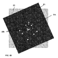
図4A−4Cは、フィルタリングマスクアッセンブリ120を示す図であり、このアッセンブリは、通常符号5の位置に複数の離間した開口を規定している。この例では、マスクアッセンブリは、図4Bに示すように二枚のプレートP1及びP2で形成され、少なくとも一枚のプレートが軸RAを中心に互いに対して回転可能である、シングルマスクを規定している。各プレートには、複数の開口が形成されている。プレートの相対的回転により、プレートの各方向が放射回収用の異なる活性開口アレイ(空間フィルタリングパターン)を作る。この非限定的な例では、プレートの一方、例えばプレートP2が,所望の選択した開口アレイセットを作るのに必要なすべての開口を含むように構成されているが、他方のプレートP1は、同じ開口配置を有するが、同じプレート内の少なくとももう一つのアレイに比べて、少なくとも一方のアレイが異なる角度方向を有するように構成されている。より詳細には、マスクアッセンブリが、二枚のプレートP1及びP2が角度方向φ=0で整列している場合に、プレートP1の開口アレイ10aに対して開口5が、プレートP2の対応する開口と重なっており、したがって、この開口を通って放射が透過するように構成されている(図4A)。二枚のプレートの内の少なくとも一方が、他方のプレートに対して回転するため、プレート間の角度方向が異なり、開口間に異なる重なりができて、異なる活性開口セットを提供する。図4Bと4Cは、プレート間の角度方向をそれぞれ30°と60°としたアレイを例示しており、異なる活性開口アレイ10bと10bができている。
FIGS. 4A-4C illustrate a
図5は、マスクアッセンブリ120の別の構成を例示している。ここでは、マスクアッセンブリは、複数の開口のあるマスクと、このマスクに整列し、マスク近傍に配置したスペクトルフィルタを具えている。スペクトルフィルタは、異なる放射回収セッションで、異なるスペクトル透過(ここでは、単純にするために原色R,G,Bが示されている)を有するように操作可能である。スペクトル透過は開口全体が一またはそれ以上のスペクトル帯域を透過させるようになっている。開口の数とその配置(開口のサイズ、相対位置、及びスペクトルフィルタのスペクトル透過の制御されたバリエーションによる開口に関連するスペクトル帯域群を含む)は、上述した通り所望のトータル有効透過関数を提供するように選択される。
FIG. 5 illustrates another configuration of the
図6A乃至6Fを参照すると、本発明の異なる実施例の原理が示されている。この例では、開口アレイセットが、開口が光軸に沿って離間して、すなわち、放射回収面の異なる面に位置するように配置されている。換言すると、開口は、いわゆる主回収面U1を含むあらかじめ決められた放射回収面と、主回収面に比べて画像面により近くにあるいはより遠くに位置する少なくとも一つの別の面を規定するように位置している。この例では、3つのこのような回収面が示されている。この構成では、より近い面U2の開口による放射回収のローカル有効透過関数と、より遠い面U3の開口が、それぞれ、主回収面U1の開口の開口に対して空間ドメイン中で伸びたり縮んだりしている。この伸びる/縮む要因は、演繹的に知られている。次いで、回収面U2及びU3の開口による放射回収に対応する画像データピースを、演繹的に知られている伸びる/縮む要因を各ローカル有効透過関数に適用することによって処理して、回収面U1、U2、U3についての結果を足し合わせ、トータル有効透過関数を得る。上述したように、開口の数と配置は、上述した所望のトータル有効透過関数を提供するように選択される。 With reference to FIGS. 6A-6F, the principles of different embodiments of the present invention are illustrated. In this example, the aperture array set is arranged such that the apertures are spaced along the optical axis, i.e. located on different surfaces of the radiation collection surface. In other words, the aperture defines a predetermined radiation recovery surface including a so-called main recovery surface U1 and at least one other surface located closer to or further from the image surface than the main recovery surface. positioned. In this example, three such recovery surfaces are shown. In this configuration, the local effective transmission function of the radiation recovery by the opening of the closer surface U2 and the opening of the farther surface U3 extend or contract in the spatial domain relative to the opening of the opening of the main recovery surface U1, respectively. ing. This factor of stretching / shrinking is known a priori. The image data pieces corresponding to the radiation collection through the apertures of the collection surfaces U2 and U3 are then processed by applying a priori known expansion / contraction factors to each local effective transmission function to obtain the collection surface U1, The results for U2 and U3 are added together to obtain a total effective transmission function. As described above, the number and arrangement of apertures are selected to provide the desired total effective transmission function described above.
以下は、本発明の上述した撮像技術の動作原理についての記載である。 The following is a description of the operating principle of the imaging technique described above of the present invention.
この目的で、N個のピンホールを有する開口アレイを通って回収された入力放射によって検出器140に形成された単一画像ピースは:
このフーリエ変換した画像データピースは、単一ピンホール画像の生成物として表すことができ、アレイ構造は:
なお、単一アレイのピンホールを通る放射透過は、一般的に、アレイの異なるピンホールを通る放射成分間に干渉を引き起こす。したがって、単一ピンホールより多い、単一ピンホールアレイの有効透過関数F(u,v)は、典型的には所定の空間周波数に対してゼロ透過である。空間周波数の感度の低減を防止するため、本発明の技術は、所定数の2またはそれ以上の開口アレイを使用している。 It should be noted that radiation transmission through a single array of pinholes typically causes interference between radiation components through different pinholes of the array. Thus, the effective transmission function F (u, v) of a single pinhole array, more than a single pinhole, is typically zero transmission for a given spatial frequency. In order to prevent a reduction in spatial frequency sensitivity, the technique of the present invention uses a predetermined number of two or more aperture arrays.
一般的に、フィルタリング制御モジュール165は、第1の開口アレイを選択し、画像取得モジュール170は、露出時間t1内の放射回収に対応する画像データピースを生成し、第2開口アレイは、露出時間t2内の同じ対象領域からの放射回収に使用される。追加の開口アレイを使用している場合についても同様である。複数のL個のアレイについては、各々を露出時間t1間使用し、結果としてのフーリエ変換した画像データは:
これに関して、画像データピースの足し合わせが、全露出時間入力放射を回収している検出器140によって行われ(すなわち、すべての開口アレイを通る回収の間入力放射に露出される)、「組み合わせた」露出の読み出しを提供するか、検出器140によって提供される画像データピースの和を決定する画像処理モジュール180によって行われる。
In this regard, the summing of the image data pieces is performed by the
全開口アレイの個々の有効透過関数の和は、対応する露出時間とともに、トータル有効透過関数を(TETF)を提供する。
このように、本発明によれば、開口アレイセットが、トータル有効透過関数G(u,v)が空間周波数に対する非空透過を所定の限界まで提供するように選択される。このような所定の限界は、対応する直径の単一ピンホールを用いた放射回収によって得られる最大解像度によって決まる。より詳細には、開口アレイ/マスクと対応する露出時間が、
したがって、トータル有効透過関数は、撮像システム100で用いる開口アレイと、対応する露出時間によって決まる。
Thus, the total effective transmission function is determined by the aperture array used in the
このように、画像処理モジュール180は、
空間座標システムにおける画像データを決定するために、画像処理モジュールは逆フーリエ変換を決定することができる。なお、G(u、v)−1は、適宜のアルゴリズムによって決まる。一般的に、リニアマトリックスを画像の再構築に用いることができる。この結果、ウイナーデコンボリューションアルゴリズムを用いて、G(u,v)−1を決めることもできる。 To determine image data in the spatial coordinate system, the image processing module can determine an inverse Fourier transform. Note that G (u, v) −1 is determined by an appropriate algorithm. In general, a linear matrix can be used for image reconstruction. As a result, G (u, v) −1 can also be determined using the winner deconvolution algorithm.
一般的には、画像データピースの強度マップの和が決定され、次いで、トータル有効透過関数によって生じる歪効果を逆にして、回復画像データを生成する。 In general, the sum of the intensity maps of the image data pieces is determined, and then the restored image data is generated by reversing the distortion effect caused by the total effective transmission function.
ウイナーデコンボリューションは、コンボリューションベースの問題に加わる信号の是正に使用される。一般的に、システムにy(r)=h(r)*x(r)+n(r)が与えられ、ここで*はコンボリューションオペレータ、x(r)は入力信号(通常、対象領域の画像データ)、h(r)はシステムのインパルス応答、n(r)は、ノイズなどの未知の信号、y(r)は観察した/測定した信号である。なお、空間ドメインに関連する本発明の技術として、ここではウイナーアルゴリズムは、rで規定される空間座標を用いて記載されている。 Winner deconvolution is used to correct signals that add to convolution-based problems. In general, y (r) = h (r) * x (r) + n (r) is given to the system, where * is a convolution operator and x (r) is an input signal (usually an image of the target area). Data), h (r) is the impulse response of the system, n (r) is an unknown signal such as noise, and y (r) is the observed / measured signal. As a technique of the present invention related to the spatial domain, the winner algorithm is described here using spatial coordinates defined by r.
ウイナーデコンボリューションは、通常、オペレータg−1(r)を認識するのに使用して、
![]()
![]()
![]()
![]()
また、上述したように、開口アレイセットは所望の解像度制限内の空間周波数についてトータル有効透過関数が非空である条件を満たすように選択される。様々なデコンボリューションアルゴリズムから知られているように、有効透過関数のゼロの(あるいはゼロに近い)値は、回復画像データにおいてノイズを増幅させ、信号対ノイズ比を低くする。 Also, as described above, the aperture array set is selected to satisfy the condition that the total effective transmission function is non-empty for spatial frequencies within a desired resolution limit. As is known from various deconvolution algorithms, a zero (or near zero) value of the effective transmission function amplifies noise in the recovered image data and lowers the signal-to-noise ratio.
図7を参照すると、撮像システム100で使用する開口アレイセットの選択方法が例示されている。まず、システムの所望のパラメータを決定する必要がある。結果としての画像解像度が、マスクから検出器Fまでの距離、対象物からマスクZまでの距離、及び、式2を参照して上述したように使用した放射波長とともに、開口径に応じて決定される(ステップ1010)。いくつかの構成では、最小開口径は、所望の解像度を規定するように選択され、一またはそれ以上の追加の、より大きい径を選択して、画像輝度をさらに高めるたことができる。次の設計ステップ(1020)では、所望のエネルギィの伝達が決定される。エネルギィの伝達は、単一ピンホールシステムに対する、あるいは、標準光学撮像システムに対する改良ファクタとして決定できる。エネルギィ伝達は、放射強度改良(RII)ファクタとして表すことができ、これは、アレイにおける開口数と使用する開口数を決定するのに使用される。最大RIIは、比率:
この段階で、開口アレイの数と各アレイにおける開口の配置に関する一般的決定がなされる(1030)。例えば、2の所望のRIIについて、軸に沿って二つの開口を各々が有する二つの開口アレイを使用することができる。一般的に、開口アレイの数は、できるだけ少ないが、式9の所望の条件を提供するように選択される。さらに、各アレイにおける開口の配置は、一次元、すなわち、軸に沿って開口を配置してもよく、二次元であってもよい。 At this stage, a general decision is made regarding the number of aperture arrays and the placement of the apertures in each array (1030). For example, for two desired RIIs, two aperture arrays each having two apertures along the axis can be used. In general, the number of aperture arrays is as small as possible, but is selected to provide the desired conditions of Equation 9. Furthermore, the arrangement of the openings in each array may be one-dimensional, that is, the openings may be arranged along the axis, or may be two-dimensional.
ステップ1040では、第1アレイの開口の配置が決められる。なお、アレイを選択する順番は、撮像セッションにおいては重要ではない。一般的に、第1アレイの開口の配置は、任意に決めることができるが、一般的には、放射回収面の中心に一の開口が単純に配置され、選択した軸に沿ってそこから所定の距離に一の開口が配置されることが好ましい。二次元配置の一般化は、第2の軸に沿った一次元配置及び/又はこのような一次元配置の回転をコピーすることによって行われる。
In
第1の開口が選択されると、対応する有効透過関数が決定され、「問題のある」空間周波数がマークされる(1050)。上述したように、有効透過関数は式6によって決定され、マークした「問題のある」空間周波数は、F(l)(u1,v1)=0を満足しているか、あるいは所定のスレッシュホールドの下(例えば、0.1以下)である。なお、このような空間周波数は、開口径によって規定される解像度制限内でのみマークされる。
Once the first aperture is selected, the corresponding effective transmission function is determined and the “problem” spatial frequency is marked (1050). As described above, the effective transmission function is determined by
この段階で、追加の開口アレイを決定し(1060)、開口の数と径が、所望の解像度とエネルギィ伝達に応じて選択される一方、開口の配置が決められて、前のアレイについてマークして空間周波数の対応する有効透過関数の有限値を提供する(1070)。このプロセスは、2、3、あるいはそれ以上の開口アレイについて、適宜の開口アレイセットが選択されるまで行われる(1080)。 At this stage, additional aperture arrays are determined (1060), and the number and diameter of the apertures are selected according to the desired resolution and energy transfer, while the aperture placement is determined to mark the previous array. Providing a finite value of the corresponding effective transmission function of the spatial frequency (1070). This process is performed for 2, 3, or more aperture arrays until an appropriate aperture array set is selected (1080).
なお、開口アレイセットは、撮像システムの設計と組み立て用にあらかじめ選択することができる。代替的に、撮像システム100のプロセッサユニット160が、所望の解像度とエネルギィ伝達に関する入力パラメータに応じて適宜の開口アレイセットを決定するように構成したセット選択ユニット(図2の190)を具えていてもよい。一般的に、前者の方法は、放射ブロックマスクに開けたピンホールの使用に適しており、後者は、電子的に制御されて変化するパターン化マスク120の使用により適している。
Note that the aperture array set can be pre-selected for imaging system design and assembly. Alternatively, the
さらに、適宜の開口アレイセットの選択は、様々な空間周波数についての開口アレイの透過を最適化するように構成される。このため、選択プロセスは、推定したトータル有効透過関数を決定するステップを具えており、すべてに開口アレイについて同じ露出時間を仮定する。推定した有効透過関数は、次いで、ピンホール透過関数(PTF)と比較される。一般的に、開口アレイセットは、解像度制限を用いて空間周波数の透過を最適化するように選択され、これによって、対象領域の撮像を最適化する。このため、開口アレイ、並びに対応する露出時間は、所望の解像度制限内における少なくともいくつかの空間周波数、すなわち、トータル有効透過関数がPTFの伝達より大きい伝達を提供するように選択される。 Further, the selection of the appropriate aperture array set is configured to optimize the aperture array transmission for various spatial frequencies. For this reason, the selection process comprises determining an estimated total effective transmission function, all assuming the same exposure time for the aperture array. The estimated effective transmission function is then compared to the pinhole transmission function (PTF). In general, the aperture array set is selected to optimize spatial frequency transmission using resolution limitations, thereby optimizing imaging of the region of interest. For this reason, the aperture array, as well as the corresponding exposure time, is selected such that at least some spatial frequencies within the desired resolution limit, ie, the total effective transmission function, provides a transmission that is greater than that of the PTF.
上述した技術は、三次元画像データの取得にも使用できる。特に、この技術によれば、対象領域から画像データピースを得て、取得した画像データピースから深さ情報を決定することができる。図8を参照すると、画像システム100から異なる距離に位置する対象物を撮像して、深さ情報を決定する方法が記載されている。図に示すように、撮像システム100又はその装置のパターン化したマスク120から異なる距離に位置する対象物は、検出器上に異なる画像を生成する。これは、各開口アレイの複数の開口によるものである。一般的に、対象物をパターン化したマスク間の距離Zが、撮像に使用する2またはそれ以上の開口アレイの開口間の距離のオーダである場合、2またはそれ以上の離間したピンホールを通って撮像した画像は、画像データピースのような立体を提供する。特に、図8に示すように、撮像システムからそれぞれ距離Z1およびZ2に位置する対象物2a及び2bは、実際、異なる角度方向において異なる開口を見ている。したがって、対象物2aを伝達し、最も上のピンホール5bを通る放射は、検出器140に届いて画像8a1を生成する。これは、一方では、対象物2bから伝達して同じピンホール5bを通る放射が、検出器140上の若干異なる位置に画像8a2を生成する。この効果は、上述の式1にしたがって異なる対象物について倍率Mを変えた結果と考えることができる。
The technique described above can also be used to acquire 3D image data. In particular, according to this technique, it is possible to obtain an image data piece from the target area and determine depth information from the acquired image data piece. Referring to FIG. 8, a method for determining depth information by imaging an object located at a different distance from the
このため、撮像システム100のプロセッサユニット160は、対象領域内の対象物の期待した距離、並びに所望の深さ解像度に関する所定の情報を用いて、異なる距離に応じて異なる有効透過関数を決定する。このような三次元情報は、通常、上述した近距離撮像においてより有効であるが、深さ情報は、遠距離においても本発明のシステムによって取得した画像データピースに基づいて決定することができる。
For this reason, the
プロセッサユニット160は、したがって、画像データピースから抽出すべき所望の深さ解像にしたがって、有効透過関数の変数を決定するように構成した深さ解像プレプロセッサ195を具えていてもよい。しかしながら、撮像システムの深さ解像に対応する有効透過関数は、あらかじめ構成して、システムに提供する、例えば、対応するストレージユニットに保存するようにしてもよい。
The
一般的に、深さ情報を提供するには、有効透過関数をパターン化したマスク120に対する対象物の様々な位置について決定することができる。開口アレイの開口の実際の位置は、dn−actualと記載されており、式1に規定されているあらかじめ選択した倍率ファクタM=0(すなわち、無限大の基準対物面)について規定されており、マスクから異なる距離Zに位置して、倍率M=M1を有する対象物については、アレイ内の開口の有効位置が、
したがって、新しい有効深さ透過関数、F(l) Z(u,v)を各アレイにと各距離Zについて、規定することができ、また、新しいトータル有効深さ透過関数がG’Z(u,v)も規定できる。 Thus, a new effective depth transmission function, F (l) Z (u, v) can be defined for each array and for each distance Z, and a new total effective depth transmission function is G ′ Z (u , V) can also be defined.
画像データピースを検出器140上に回収したのち、画像処理モジュール180は、深さ解像プレプロセッサ195によって提供される深さ解像有効透過関数を用いて、複数の回復画像データセットを決定できる。これは、各々が、対象物距離についての対応する有効透過関数G’Z(u,v)に関連して、対象物距離Zを表している。このように、画像処理モジュールは、以下の通り、複数の回復画像データを生成する。
なお、対応する有効深さ透過関数、G’Z(u,v)によって取得したZ面の数が、深さ解像度を決定する。さらに、最大の可能な深さ解像度は、三角測量法により、及び検出器ユニット140の幾何学的解像度に応じて決まる。この点に関して、マスクから対象物の距離の変化は、少なくとも一の開口アレイの少なくとも一の開口を通る放射透過によって生成された画像が、基準対物面の距離に対して少なくとも一画素分シフトした場合に検出できる。この条件は、
特に、様々な(この場合最大)深さ位置からみられる開口の相対位置の変化は、検出器の画素間の離間より大きい。さらに、深さ位置間を差別化するのに同様の条件が提供される。
なお、深さ情報の場合は、画像処理ユニット180は、各Z−面についての画像データを再構築するように構成されている。各再構築したデータについては、対応するZ−面に位置する対象物のみが、正確に再構築され、合焦画像データを提供する。その他のZ−面に位置する対象物は、「焦点外」の画像データと同様のぼやけた再構築画像データを提供するであろう。
In the case of depth information, the
以下に、撮像における本発明の技術とシステムの使用を例示する。 The following illustrates the use of the techniques and systems of the present invention in imaging.
例1:図9A−9Kは、3つの開口アレイと、対応する有効透過関数及び試験対象物の画像を示す。図9A−9Cは、直径170μmのピンホールを有する3つの開口アレイの開口構造を示す。図6Dは、これらの開口の位置と番号を示す。開口アレイセットは、同じ直径の単一ピンホールに比べて5.66倍明るい撮像を提供する。図9A−9Cに示す3つのアレイ中の開口の配置は、表1に示されており、この表は、検出器の画素サイズとシステム内の距離(すなわち、UとZ)に応じて決定した相対ユニットのものである。
図に示すように、開口1、5および9はマスクの中央に位置しており、残りの開口は周りに配置されて、非空有効透過関数を提供する。図9E及び9Fは、各開口アレイについての有効透過関数と選択された露出時間加重に基づいたトータル有効透過関数の絶対値を示す。図9E及び9Fに示すように、グラフラインG0は、マスクの中央に位置しており、同じ寸法の単一ピンホール透過関数である。グラフF1、F2、及びF3は、図9A−9Cの各開口アレイの有効透過関数である。これらの図からみられるように、単一ピンホールの有効透過関数は、主ローブが解像限界を規定しているsinc(f)関数の形である。図9Aの開口アレイは、いくつかのゼロ点を有するが、図9及び9Cは、異なる空間周波数でゼロ値を有するように設計されており、解像限界内での空間解像度について、非空値を伴うトータル有効透過関数Gtotalを提供している。なお、ここに示す開口アレイは、実際には、一次元アレイのレプリカとして構成されており、したがって、有効透過関数は、完全に一次元グラフに記載することができる。
As shown, the
図9G乃至9Kは、上述した技術の有効性を示す試験結果を示す図である。図9Gは、直径170μmの単一ピンホールを通る可視光で撮像した試験対象物の画像である。図9Hは、直径250μmのピンホールを通る同じ対象物の画像である。図9Iは、直径350μmのピンホールを通る対象物の画像である。図9Jは、連続露出の後、図9A−9Cの3つの開口アレイを通り、後処理なしで生成した生画像データである。図9Kは、後処理後の再構築した画像を示す。 9G to 9K are diagrams showing test results showing the effectiveness of the above-described technique. FIG. 9G is an image of the test object imaged with visible light passing through a single pinhole having a diameter of 170 μm. FIG. 9H is an image of the same object passing through a 250 μm diameter pinhole. FIG. 9I is an image of an object passing through a pinhole having a diameter of 350 μm. FIG. 9J is raw image data generated without post-processing through the three aperture arrays of FIGS. 9A-9C after continuous exposure. FIG. 9K shows the reconstructed image after post-processing.
図に示すように、ピンホール径が大きくなると、画像の輝度も大きくなるが、解像度は落ちる。これは、上述の技術によって生成した再構築画像は、解像度が低下することなくより高い画像輝度を提供できるが、より大きな信号対ノイズ比を提供する。 As shown in the figure, as the pinhole diameter increases, the brightness of the image increases but the resolution decreases. This allows the reconstructed image generated by the above-described technique to provide higher image brightness without loss of resolution, but provides a greater signal to noise ratio.
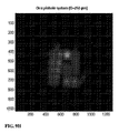
例2:図10A−10Eは、図9A−9Cに例示した構造の一次元及び二次元開口アレイを用いたシミュレーション結果の画像データを示す。一次元開口アレイは、図9に例示した開口1、2;5、6;および14、9、10を具える開口位置で構成されており、2.33の画像輝度の増加を提供している。図10Aは、同じ直径の単一ピンホールを通って撮像した画像を示す。図10Bは、直径が150%大きいピンホールを通って撮像した画像を示す。図10Cは、一次元開口アレイを用いて上述した技術にしたがって撮像した再構築画像を示す。図10D及び10Eは、二次元開口アレイを用いて、マルチ開口技術にしたがって撮像した生画像データと再構築画像をそれぞれ示す。
Example 2: FIGS. 10A-10E show image data of simulation results using one-dimensional and two-dimensional aperture arrays of the structure illustrated in FIGS. 9A-9C. The one-dimensional aperture array is made up of aperture
図に示すように、開口径が大きくなると、解像度を犠牲にして画像輝度が高くなる。これに対して、本発明による再構築画像は、解像度を低下させることなく輝度を高める。さらに、この技術によって、より小さな開口を使用することができ、これによって、同じ又はより大きな画像輝度に対する解像度を上げることができる。 As shown in the figure, as the aperture diameter increases, the image brightness increases at the expense of resolution. On the other hand, the reconstructed image according to the present invention increases the luminance without reducing the resolution. In addition, this technique allows the use of smaller apertures, which can increase the resolution for the same or greater image brightness.
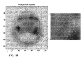
例3:図11A−11Jは、本発明の技術を用いたガンマ撮像のシミュレーションを示す。図11Aは、アレイ1−3の構造と対抗する開口寸法を示す。図11B−11Gは、アレイと対応する有効透過関数を示すグラフである。図11Hは、単一ピンホールの透過、並びに、アレイの個別及びトータル有効透過関数を示す。図11I−11Jは、ガリウム67の放射を使用して、骨髄炎の断面スライス(ネガティブカラー)の骨スキャンをエミュレートした、単一ピンホール(図11I)を用いて撮像したシミュレーション画像と、図11Aに示すピンホールアレイで本発明の技術を用いた再構築画像(図11J)を示す。図11I、11Jともに、特徴部分を拡大して示しており、図に示すように、再構築画像はより高い解像度と信号対ノイズ比を提供しており、したがって、単一ピンホールによって生成した画像で解像できない特徴(矢印で示す)についての情報を提供している。 Example 3 FIGS. 11A-11J show a simulation of gamma imaging using the technique of the present invention. FIG. 11A shows the opening dimensions to counter the structure of array 1-3. 11B-11G are graphs showing the effective transmission function corresponding to the array. FIG. 11H shows the transmission of a single pinhole and the individual and total effective transmission functions of the array. FIGS. 11I-11J are simulation images taken using a single pinhole (FIG. 11I), emulating a bone scan of a cross-sectional slice of osteomyelitis (negative color) using gallium 67 radiation, and FIG. FIG. 11A shows a reconstructed image (FIG. 11J) using the technique of the present invention with the pinhole array shown in FIG. 11A. 11I and 11J both show enlarged features, as shown, the reconstructed image provides a higher resolution and signal-to-noise ratio, and thus an image generated by a single pinhole. Provides information about features that cannot be resolved by (indicated by arrows).
開口アレイは、同じ径の単一ピンホールシステムに対して、輝度が2.33高くなっている。図に示すように、開口アレイは、単一ピンホール寸法の解像度限界内での空間周波数について、トータル有効透過関数(図11HのGtotal)が非空となるように選択されている。以下の表2は、信号とノイズの測定結果を示す。
表2に示すように、本発明の技術によって提供される信号対ノイズ比(SNR)は、単一ピンホールシステムに対して優位に高い。この改良は、
![]()
![]()
![]()
![]()
例4:図12A−12Cは、表面に異なる密度で複数のリード線を有する、解像度試験対象物のガンマ撮像の実験結果を示す。図12Aは、直径4.45mmの単一ピンホールを通した試験対象物の画像を示す。図12Bは、直径2mmの単一ピンホールを用いた試験対象物の画像を示す。図12Cは、直径2mmのピンホールを用いて、図12Aに示す開口アレイセットで本発明の技術を用いた試験対象物の再構築画像を示す。 Example 4: Figures 12A-12C show experimental results of gamma imaging of a resolution test object having multiple leads at different densities on the surface. FIG. 12A shows an image of the test object through a single pinhole with a diameter of 4.45 mm. FIG. 12B shows an image of the test object using a single pinhole with a diameter of 2 mm. FIG. 12C shows a reconstructed image of a test object using the technique of the present invention with the aperture array set shown in FIG. 12A, using a 2 mm diameter pinhole.
図に示すように、図12Aの画像は、比較的明るいが、対象物の二つの領域の明確なライン間を区別するのに十分な解像度を提供していない。図12Bのより小さなピンホールの使用により解像度は上がるが、画像輝度が制限されており、領域の一方について、画像の輝度がこの明確なラインを認識するには十分でない。これに対して、本発明の使用によれば、解像度が高くなるとともに、図12Cにみられるように、試験対象物のすべての領域における明確なラインを認識するのに十分な輝度を提供している。 As shown, the image of FIG. 12A is relatively bright but does not provide sufficient resolution to distinguish between distinct lines in the two regions of the object. Using the smaller pinhole of FIG. 12B increases resolution, but the image brightness is limited, and for one of the regions, the image brightness is not sufficient to recognize this distinct line. In contrast, the use of the present invention provides high resolution and sufficient brightness to recognize clear lines in all regions of the test object as seen in FIG. 12C. Yes.
例5:図13A−13Fは、図11Aに示す開口アレイを用いて上述した技術に基づいた実験的な深さ解像撮像を示す。図13Aは、パワーが異なる4つの放射源を有するケースを示しており、これらの放射源は、このケースの前面から異なる距離に配置されている。近い源と遠い源間の距離は60mmである。図12Bは、撮像スキームとこのケースの源の位置の側面を示しており、これらの源の異なる位置を示している。図12Cは、直径2mmの単一ピンホールを通して撮像して生成した対象物の画像を示す。この画像においては、4つの放射源すべてを制限された解像度と輝度で見ることができる。さらに、この画像は、マスクに対する源の距離に関するデータを提供していない。これは、ピンホールベースでの撮像の焦点深度が高い(実際には無限大)ことによる。図13Dは、図11Aに示す3つの開口アレイを通して放射を回収した生画像を示す。この画像は、ぼやけており、意味のある情報を提供するには再構築する必要がある。このような情報は、図13E及び13Fに提供されており、これらの図は、距離Zmax及びZminのそれぞれについての画像再構築結果を示している。この距離は、画像であり、所望の深さ解像である対象物の既存の厚さに関する知識にしたがって規定される。図に示すように、各回復画像において、はっきりマークされた二つの源と、その他の位置にある源からの入力放射からの複数ポイントがある Example 5: FIGS. 13A-13F show experimental depth resolution imaging based on the technique described above using the aperture array shown in FIG. 11A. FIG. 13A shows a case with four radiation sources with different powers, which are located at different distances from the front of the case. The distance between the near and far sources is 60 mm. FIG. 12B shows a side view of the imaging scheme and the location of the sources in this case, showing the different locations of these sources. FIG. 12C shows an image of an object generated by imaging through a single pinhole having a diameter of 2 mm. In this image, all four radiation sources can be seen with limited resolution and brightness. Furthermore, this image does not provide data regarding the source distance to the mask. This is due to the high depth of focus (in practice infinite) for pinhole-based imaging. FIG. 13D shows a raw image where radiation was collected through the three aperture array shown in FIG. 11A. This image is blurry and needs to be reconstructed to provide meaningful information. Such information is provided in FIGS. 13E and 13F, which show the image reconstruction results for distances Z max and Z min , respectively. This distance is an image and is defined according to knowledge of the existing thickness of the object that is the desired depth resolution. As shown in the figure, in each recovered image there are two points from the input radiation from two clearly marked sources and sources at other locations
この技術は、異なる位置から複数の画像を集める必要なく、腫瘍の位置決め用のX線あるいはガンマ線撮像、あるいは、その他の放射線源の使用を可能にする。また、一般的に、放射回収時間を低減し、したがって、より早く減衰する放射線源の使用が可能となり、患者へのダメージが低減する。 This technique allows the use of X-ray or gamma imaging for tumor positioning or other radiation sources without having to collect multiple images from different locations. Also, in general, radiation recovery time is reduced, thus allowing the use of a radiation source that decays faster, reducing damage to the patient.
例6:図14A−14C並びに図15A−15Dは、本発明の技術を使用するのに適した代替の開口アレイ配置を示す。上述したように、開口アレイにおける開口の配置は、所望の解像度限界内ですべての空間周波数において非空透過を提供するように選択される。 Example 6: FIGS. 14A-14C as well as FIGS. 15A-15D show alternative aperture array arrangements suitable for using the techniques of the present invention. As described above, the placement of the apertures in the aperture array is selected to provide non-empty transmission at all spatial frequencies within the desired resolution limit.
図14A及び14Bは、二つの開口アレイセットを示しており、各々が所定の配置において25の開口を有する。これらは互いに、対応する直径の単一ピンホールの解像度内で、並びにこの解像度を超えて、すべての空間周波数における有限透過を伴う有効透過関数を提供している。トータル有効透過関数の絶対値は図14Cに示す。このグラフは、同じ直径の単一ピンホールの透過G0に対するトータル有効透過関数Gtotalを示す。このような開口アレイセットは、25のRIIを提供し、したがって、単一ピンホールを通る撮像に対して撮像輝度が25倍になる。代替的に、この技術を用いて、同じ輝度で露出時間を短くすることができる。 14A and 14B show two aperture array sets, each having 25 apertures in a predetermined arrangement. They provide an effective transmission function with finite transmission at all spatial frequencies within and beyond the resolution of a single pinhole of corresponding diameter. The absolute value of the total effective transmission function is shown in FIG. 14C. This graph shows the total effective transmission function G total for the transmission G 0 of a single pinhole of the same diameter. Such an aperture array set provides 25 RIIs, thus imaging brightness is 25 times that for imaging through a single pinhole. Alternatively, this technique can be used to shorten the exposure time at the same brightness.
さらに、図15A−15Dは、ピンホール径が異なる開口アレイの使用を例示している。図15Aは、同じ配置の3セットの開口アレイを示す。セットIは、図9A−9D及び表1で述べた開口配置と同様である。セットIIは、追加の開口で構成されており、セットIIIは、異なる径の開口を提供して輝度をより高くしている。図15B−15Dは、単一ピンホールの透過に対するそれぞれのトータル有効透過関数を示す。特に、図15Bは、セットIのトータル有効透過関数を示し、図15Cは、セットIIのトータル有効透過関数を示し、図15Dは、セットIIIのトータル有効透過関数を示す。図に示すように、追加の開口を使用することで、より多くの空間周波数について、単一ピンホールの透過に比べてモジュール内でトータル有効透過関数をより大きくしている。このように、輝度とコントラストの両方に関してより高い撮像効率を提供する一方で、解像度及び/又は露出時間を必要とせず、ロスしない。 Further, FIGS. 15A-15D illustrate the use of aperture arrays with different pinhole diameters. FIG. 15A shows three sets of aperture arrays in the same arrangement. Set I is similar to the aperture arrangement described in FIGS. 9A-9D and Table 1. Set II consists of additional openings, and Set III provides different diameter openings for higher brightness. Figures 15B-15D show the respective total effective transmission functions for single pinhole transmission. In particular, FIG. 15B shows the total effective transmission function for Set I, FIG. 15C shows the total effective transmission function for Set II, and FIG. 15D shows the total effective transmission function for Set III. As shown in the figure, the use of additional apertures increases the total effective transmission function within the module for more spatial frequencies than for single pinhole transmission. Thus, while providing higher imaging efficiency in terms of both brightness and contrast, no resolution and / or exposure time is required and lost.
このように、本発明は、2またはそれ以上の開口アレイを通して対象領域を撮像し、取得した画像データを再構築して、対象領域の再構築画像を提供する技術とシステムを提供している。この技術は、限定するものではないが、赤外線放射、可視光放射、紫外線放射、X線放射、ガンマ線放射、あるいはブロック材料を使用できるあらゆるその他の波長を含めて、どのような波長の電磁放射でも使用することができる。また、この技術を用いて、撮像システム又は対象物を移動させる必要なく画像データに基づいて深度情報を提供することができる。 As described above, the present invention provides a technique and system for imaging a target region through two or more aperture arrays, reconstructing the acquired image data, and providing a reconstructed image of the target region. This technique is not limited to infrared radiation, visible light radiation, ultraviolet radiation, X-ray radiation, gamma radiation, or any other wavelength of electromagnetic radiation that can use blocking materials. Can be used. Also, using this technique, depth information can be provided based on image data without having to move the imaging system or object.
Claims (24)
(a)対象領域からの入力放射を所定数の複数の選択された開口アレイのセットを通して回収するステップであって、各開口アレイが所定の開口配置を有するとともに、前記入力放射を回収時間ピリオドの間回収し、選択された開口アレイのセットと対応する回収時間ピリオドが放射回収のトータル有効透過関数を規定している、ステップと;
(b)前記回収した入力放射から画像データを生成するステップであって、当該画像データが、前記開口アレイを通って各々回収した入力放射に対応する所定数の画像データピースを具える、ステップと;
(c)放射回収のトータル有効透過関数を用いて前記画像データピースを処理し、前記対象領域を示す回復画像データを決定するステップと;
を具え、
前記開口アレイは、開口アレイの透過関数が異なる空間周波数でゼロ値を有するように選択され、それにより、所定の最大空間周波数より低い空間周波数について非空透過を有する前記トータル有効透過関数を提供することを特徴とする方法。 In a method of imaging a target area:
(A) collecting input radiation from the region of interest through a set of a plurality of selected aperture arrays of a predetermined number, each aperture array having a predetermined aperture arrangement, and the input radiation is collected in a collection time period ; and during recovery, and it defines the total effective transmission function of the corresponding recovery time periods release morphism collection with a set of selected aperture array, comprising the steps;
(B) generating image data from the collected input radiation, the image data comprising a predetermined number of image data pieces each corresponding to the collected input radiation through the aperture array; ;
(C) release morphism with total effective transmission function of the recovery process the image data piece, and determining the restored image data indicating the target area;
The equipped,
The aperture array is selected such that the transmission function of the aperture array has a zero value at different spatial frequencies, thereby providing the total effective transmission function having non-empty transmission for spatial frequencies below a predetermined maximum spatial frequency. A method characterized by that.
(a)回収する入力放射の空間フィルタリングを行う放射回収面を規定するマスクであって、複数の開口を具え、前記マスクの複数の所定数の空間フィルタリングパターンを選択的に提供するよう構成され動作可能であり、各々のフィルタリングパターンが前記放射回収面内に所定の開口配置によって形成されているマスクと;
(b)フィルタリングモジュールと;画像取得モジュールと画像処理モジュールを具えるコントロールユニットであって、前記フィルタリングモジュールが、前記マスクを動作させて、選択された露出時間ピリオドの間に異なるフィルタリングパターンによって前記入力放射を選択的に回収するよう構成されており;前記画像取得モジュールが、前記選択された露出時間ピリオドの間に前記フィルタリングパターンをそれぞれ通る入力放射の回収に対応する画像データピースを受け取るように構成されており;前記画像処理モジュールが、前記画像データピースを受け取って処理を行い、前記マスクを通る放射回収のトータル有効透過関数を表すデータを使用して、前記入力放射が回収されている対象領域の回復画像データを決定するように構成されている、コントロールユニットと;を具え、
前記マスクの選択した複数の所定数の空間フィルタリングパターンが、異なる空間周波数でゼロ値を有する空間フィルタリングパターンの透過関数を提供するようあらかじめ選択され、それにより、所定の最大空間周波数より低い空間周波数について非空透過を有する前記トータル有効透過関数を提供することを特徴とするシステム。 In the imaging system:
(A) a mask defining a radiation collection surface for performing spatial filtering of input radiation to be collected, the mask comprising a plurality of apertures and configured to selectively provide a plurality of a predetermined number of spatial filtering patterns of the mask A mask, wherein each filtering pattern is formed in the radiation collection surface by a predetermined aperture arrangement;
(B) filtering spider Joules and; a control unit comprising an image acquisition module and an image processing module, the filtering module, the operates the mask, different filtering patterns during the exposure time period that is selected Configured to selectively collect the input radiation; and wherein the image acquisition module receives image data pieces corresponding to the collection of input radiation that respectively passes through the filtering pattern during the selected exposure time period. The image processing module receives and processes the image data pieces, and the input radiation is collected using data representing a total effective transmission function of radiation collection through the mask. To determine the recovery image data of the target area Is made, the control unit; e ingredients a,
A plurality of selected predetermined number of spatial filtering patterns of the mask are preselected to provide a transmission function of spatial filtering patterns having zero values at different spatial frequencies, thereby for spatial frequencies lower than a predetermined maximum spatial frequency Providing the total effective transmission function having non-empty transmission .
24. The system according to any one of claims 15 to 23 is configured to image with at least one input radiation in a wavelength range of infrared radiation, visible light radiation, ultraviolet radiation, X-ray radiation, and gamma radiation. A system characterized by that.
Applications Claiming Priority (3)
| Application Number | Priority Date | Filing Date | Title |
|---|---|---|---|
| US201461936402P | 2014-02-06 | 2014-02-06 | |
| US61/936,402 | 2014-02-06 | ||
| PCT/IL2015/050135 WO2015118540A1 (en) | 2014-02-06 | 2015-02-05 | System and method for imaging with pinhole arrays |
Publications (3)
| Publication Number | Publication Date |
|---|---|
| JP2017507585A JP2017507585A (en) | 2017-03-16 |
| JP2017507585A5 JP2017507585A5 (en) | 2018-03-15 |
| JP6605483B2 true JP6605483B2 (en) | 2019-11-13 |
Family
ID=53777401
Family Applications (1)
| Application Number | Title | Priority Date | Filing Date |
|---|---|---|---|
| JP2016549382A Expired - Fee Related JP6605483B2 (en) | 2014-02-06 | 2015-02-05 | Imaging system and method using pinhole array |
Country Status (5)
| Country | Link |
|---|---|
| US (2) | US10033996B2 (en) |
| EP (1) | EP3102976B1 (en) |
| JP (1) | JP6605483B2 (en) |
| IL (1) | IL246832B (en) |
| WO (1) | WO2015118540A1 (en) |
Families Citing this family (19)
| Publication number | Priority date | Publication date | Assignee | Title |
|---|---|---|---|---|
| CA2866370C (en) | 2012-03-07 | 2024-03-19 | Ziteo, Inc. | Methods and systems for tracking and guiding sensors and instruments |
| US10068740B2 (en) * | 2012-05-14 | 2018-09-04 | The General Hospital Corporation | Distributed, field emission-based X-ray source for phase contrast imaging |
| US10617401B2 (en) | 2014-11-14 | 2020-04-14 | Ziteo, Inc. | Systems for localization of targets inside a body |
| US11178349B2 (en) * | 2015-01-29 | 2021-11-16 | William Marsh Rice University | Lensless imaging system using an image sensor with one or more attenuating layers |
| DE102015218829B4 (en) * | 2015-09-30 | 2018-08-16 | Bayerische Motoren Werke Aktiengesellschaft | An image forming apparatus and method of making an array of imaging elements |
| CN106842540B (en) * | 2017-03-24 | 2018-12-25 | 南京理工大学 | Annular optical illumination high-resolution quantitative phase micro imaging method based on light intensity transmission equation |
| US11555935B2 (en) * | 2017-10-20 | 2023-01-17 | Australian Nuclear Science And Technology Organisation | Compressive imaging method and system comprising a detector, a mask, and a drive for rotating the mask about at least one of one or more axes of rotational symmetry |
| JP7063378B2 (en) | 2018-03-20 | 2022-05-09 | 日本電気株式会社 | Imaging device and imaging method |
| WO2019198073A1 (en) | 2018-04-10 | 2019-10-17 | Lensfree Ltd. | Computerized tomography system |
| CN110536049A (en) * | 2018-05-25 | 2019-12-03 | 印象认知(北京)科技有限公司 | Image capture device, image-pickup method, electronic equipment and imaging device |
| EP3671147A1 (en) * | 2018-12-21 | 2020-06-24 | IMEC vzw | Apparatus for depth-resolved hyperspectral imgaging |
| WO2020144675A1 (en) * | 2019-01-07 | 2020-07-16 | Lensfree Ltd. | System and method for use in imaging |
| JP2022526445A (en) | 2019-04-09 | 2022-05-24 | ジティオ, インコーポレイテッド | Methods and systems for high-performance and versatile molecular imaging |
| KR102199071B1 (en) * | 2019-09-24 | 2021-01-06 | 상명대학교산학협력단 | Method and apparatus for reconstructing 4D image based on integrated image |
| EP3805810A1 (en) * | 2019-10-07 | 2021-04-14 | Siemens Healthcare GmbH | X-ray imaging apparatus and x-ray imaging method |
| CN112099226B (en) * | 2020-03-06 | 2022-02-08 | 中国工程物理研究院激光聚变研究中心 | Laser beam guiding method for aiming of silk target |
| US11947048B2 (en) * | 2020-05-06 | 2024-04-02 | Waymo Llc | Crosstalk reduction for light detection and ranging (lidar) devices using wavelength locking |
| CN112926179B (en) * | 2020-12-31 | 2023-08-01 | 江苏霆升科技有限公司 | Method and device for determining parameters of intracavity ultrasonic imaging equipment based on simulation |
| CN113703178B (en) * | 2021-09-11 | 2023-05-30 | 成都航空职业技术学院 | Integrated imaging 3D display device with uniform resolution |
Family Cites Families (20)
| Publication number | Priority date | Publication date | Assignee | Title |
|---|---|---|---|---|
| US3961191A (en) * | 1974-06-26 | 1976-06-01 | Raytheon Company | Coded imaging systems |
| US5436958A (en) | 1994-08-03 | 1995-07-25 | General Electric Company | Adjustable collimator |
| DE19824460A1 (en) | 1998-05-30 | 1999-12-02 | Zeiss Carl Jena Gmbh | Arrangement and method for the microscopic generation of object images |
| WO2002056055A2 (en) * | 2000-09-29 | 2002-07-18 | Massachusetts Inst Technology | Systems and methods for coded aperture imaging of radiation- emitting sources |
| WO2004102958A1 (en) * | 2003-05-13 | 2004-11-25 | Xceed Imaging Ltd. | Optical method and system for enhancing image resolution |
| US20050243330A1 (en) | 2004-04-28 | 2005-11-03 | Simon Magarill | Methods and apparatus for determining three dimensional configurations |
| US7365917B2 (en) | 2004-08-16 | 2008-04-29 | Xceed Imaging Ltd. | Optical method and system for extended depth of focus |
| US7643952B2 (en) | 2005-04-05 | 2010-01-05 | The Board Of Trustees Of The Leland Stanford Junior University | Optical image processing using minimum phase functions |
| GB0510470D0 (en) * | 2005-05-23 | 2005-06-29 | Qinetiq Ltd | Coded aperture imaging system |
| US7187502B2 (en) | 2005-06-09 | 2007-03-06 | Microalign Techologies, Inc. | Compact optical assembly for imaging a remote object |
| GB0602380D0 (en) | 2006-02-06 | 2006-03-15 | Qinetiq Ltd | Imaging system |
| GB2434934A (en) * | 2006-02-06 | 2007-08-08 | Qinetiq Ltd | Processing coded aperture image data by applying weightings to aperture functions and data frames |
| EP2062017A4 (en) * | 2006-08-28 | 2013-05-22 | Thermo Electron Scient Instr | Spectroscope with vignetting reduction |
| JP5622571B2 (en) * | 2007-07-20 | 2014-11-12 | メディツィーニシェ・ウニヴェルジテート・インスブルックMedizinische Universitaet Innsbruck | Optical device comprising a pair of diffractive optical elements |
| GB0814562D0 (en) | 2008-08-08 | 2008-09-17 | Qinetiq Ltd | Processing for coded aperture imaging |
| WO2010119447A1 (en) | 2009-04-16 | 2010-10-21 | Doron Shlomo | Imaging system and method |
| JP5377073B2 (en) * | 2009-05-20 | 2013-12-25 | キヤノン株式会社 | Imaging apparatus, blur repair method, and program |
| US9146403B2 (en) | 2010-12-01 | 2015-09-29 | Massachusetts Institute Of Technology | Content-adaptive parallax barriers for automultiscopic display |
| US8949078B2 (en) | 2011-03-04 | 2015-02-03 | Ricoh Co., Ltd. | Filter modules for aperture-coded, multiplexed imaging systems |
| JP5830348B2 (en) * | 2011-10-26 | 2015-12-09 | オリンパス株式会社 | Imaging device |
-
2015
- 2015-02-05 WO PCT/IL2015/050135 patent/WO2015118540A1/en active Application Filing
- 2015-02-05 EP EP15746767.1A patent/EP3102976B1/en active Active
- 2015-02-05 JP JP2016549382A patent/JP6605483B2/en not_active Expired - Fee Related
- 2015-02-05 US US15/117,356 patent/US10033996B2/en active Active
- 2015-06-30 US US14/755,104 patent/US9344700B2/en active Active
-
2016
- 2016-07-19 IL IL246832A patent/IL246832B/en active IP Right Grant
Also Published As
| Publication number | Publication date |
|---|---|
| EP3102976A1 (en) | 2016-12-14 |
| US20170163961A1 (en) | 2017-06-08 |
| EP3102976A4 (en) | 2017-09-13 |
| JP2017507585A (en) | 2017-03-16 |
| US9344700B2 (en) | 2016-05-17 |
| EP3102976B1 (en) | 2020-10-07 |
| WO2015118540A1 (en) | 2015-08-13 |
| US10033996B2 (en) | 2018-07-24 |
| IL246832B (en) | 2019-03-31 |
| US20150381958A1 (en) | 2015-12-31 |
Similar Documents
| Publication | Publication Date | Title |
|---|---|---|
| JP6605483B2 (en) | Imaging system and method using pinhole array | |
| Kingston et al. | Neutron ghost imaging | |
| JP2021506168A5 (en) | ||
| JP6035772B2 (en) | Design of filter modules for aperture coded multiple imaging systems | |
| JP7246093B2 (en) | Wavefront sensor and method of use | |
| CN107850680B (en) | X-ray detector for phase contrast and/or dark field imaging | |
| GB2457836A (en) | Non-linear chirp signal | |
| JP2017502327A (en) | Apparatus and method for performing inline lens-free digital holography of an object | |
| JP2009545265A (en) | Processing method for coded aperture sensors | |
| CN108364342B (en) | Light field microscopic system and three-dimensional information reconstruction method and device thereof | |
| CN107621463A (en) | Image rebuilding method, device and microscopic imaging device | |
| US10012953B2 (en) | Method of reconstructing a holographic image and apparatus therefor | |
| CN110023726A (en) | For characterizing the measuring device and method of the radiation field of especially laser emission | |
| JP2015078976A (en) | X-ray imaging system | |
| US10993686B2 (en) | Phase contrast imaging method | |
| RU2179336C1 (en) | Method and device for shaping optical image in incoherent light (alternatives) | |
| EP3776007A1 (en) | Computerized tomography system | |
| Wang et al. | Angle-sensitive pixels: a new paradigm for low-power, low-cost 2D and 3D sensing | |
| US20210315535A1 (en) | System and method for use in x-ray imaging | |
| Hu et al. | Extended depth of field reconstruction with complex field estimation | |
| Paganin et al. | Spatial resolution, noise and information in the computational-imaging era | |
| Schwarz et al. | Time multiplexed pinholes array based imaging in the gamma and x-ray spectral range | |
| WO2023007496A1 (en) | Method and system for high photon energies imaging | |
| Lee et al. | Optimized Optomechanical Anti-Aliasing Filter for Digital Camera Photography | |
| Dang | The restoration of neutron penumbral image with adaptive iterative algorithm for signal-dependent noise. |
Legal Events
| Date | Code | Title | Description |
|---|---|---|---|
| A521 | Request for written amendment filed |
Free format text: JAPANESE INTERMEDIATE CODE: A523 Effective date: 20180131 |
|
| A621 | Written request for application examination |
Free format text: JAPANESE INTERMEDIATE CODE: A621 Effective date: 20180131 |
|
| A977 | Report on retrieval |
Free format text: JAPANESE INTERMEDIATE CODE: A971007 Effective date: 20190214 |
|
| A131 | Notification of reasons for refusal |
Free format text: JAPANESE INTERMEDIATE CODE: A131 Effective date: 20190305 |
|
| A601 | Written request for extension of time |
Free format text: JAPANESE INTERMEDIATE CODE: A601 Effective date: 20190603 |
|
| A521 | Request for written amendment filed |
Free format text: JAPANESE INTERMEDIATE CODE: A523 Effective date: 20190628 |
|
| TRDD | Decision of grant or rejection written | ||
| A01 | Written decision to grant a patent or to grant a registration (utility model) |
Free format text: JAPANESE INTERMEDIATE CODE: A01 Effective date: 20190917 |
|
| A61 | First payment of annual fees (during grant procedure) |
Free format text: JAPANESE INTERMEDIATE CODE: A61 Effective date: 20191016 |
|
| R150 | Certificate of patent or registration of utility model |
Ref document number: 6605483 Country of ref document: JP Free format text: JAPANESE INTERMEDIATE CODE: R150 |
|
| LAPS | Cancellation because of no payment of annual fees |