JP6603594B2 - Audio signal transmitting apparatus, audio signal transmitting method, control program, and computer-readable recording medium - Google Patents

Audio signal transmitting apparatus, audio signal transmitting method, control program, and computer-readable recording medium Download PDF

Info

Publication number
JP6603594B2
JP6603594B2 JP2016025044A JP2016025044A JP6603594B2 JP 6603594 B2 JP6603594 B2 JP 6603594B2 JP 2016025044 A JP2016025044 A JP 2016025044A JP 2016025044 A JP2016025044 A JP 2016025044A JP 6603594 B2 JP6603594 B2 JP 6603594B2
Authority
JP
Japan
Prior art keywords
audio signal
audio
sound
signal
reproduced
Prior art date
Legal status (The legal status is an assumption and is not a legal conclusion. Google has not performed a legal analysis and makes no representation as to the accuracy of the status listed.)
Active
Application number
JP2016025044A
Other languages
Japanese (ja)
Other versions
JP2017143479A (en
Inventor
慶浩 伊佐岡
Current Assignee (The listed assignees may be inaccurate. Google has not performed a legal analysis and makes no representation or warranty as to the accuracy of the list.)
Sharp Corp
Original Assignee
Sharp Corp
Priority date (The priority date is an assumption and is not a legal conclusion. Google has not performed a legal analysis and makes no representation as to the accuracy of the date listed.)
Filing date
Publication date
Application filed by Sharp Corp filed Critical Sharp Corp
Priority to JP2016025044A priority Critical patent/JP6603594B2/en
Publication of JP2017143479A publication Critical patent/JP2017143479A/en
Application granted granted Critical
Publication of JP6603594B2 publication Critical patent/JP6603594B2/en
Active legal-status Critical Current
Anticipated expiration legal-status Critical

Links

Images

Landscapes

  • Telephone Function (AREA)

Description

本発明は、音声出力装置に対して音声信号を送信する音声信号送信装置、音声信号送信方法、制御プログラム、およびコンピュータ読み取り可能な記録媒体に関する。   The present invention relates to an audio signal transmitting apparatus that transmits an audio signal to an audio output apparatus, an audio signal transmitting method, a control program, and a computer-readable recording medium.

従来のデジタル無線通信方式では、相手に音声の最初の部分が送信されない現象、いわゆる頭切れが発生するという問題点があった。   The conventional digital wireless communication system has a problem that the first part of the voice is not transmitted to the other party, that is, a so-called head break occurs.

上記の問題点を解決するための技術として、特許文献1に記載されているデジタル無線通信方式が挙げられる。特許文献1に記載されているデジタル無線通信方式においては、入力音声信号に対して遅延を与えることによって、頭切れの発生を抑制している。   As a technique for solving the above problems, there is a digital wireless communication system described in Patent Document 1. In the digital wireless communication system described in Patent Document 1, the occurrence of a head break is suppressed by giving a delay to the input audio signal.

具体的に、特許文献1に記載されているデジタル無線通信方式において、入力音声信号として比較的立ち上がりの緩やかな音声パターンの波形では、多少最初の部分が頭切れを起こしても相手側では、明瞭度の劣化はほとんどない。従って、遅延量は少なくてすみ、可変遅延回路の遅延量は短く設定される。   Specifically, in the digital wireless communication system described in Patent Document 1, in the waveform of an audio pattern having a relatively slow rise as an input audio signal, even if the initial portion is somewhat cut off, the other side is clear. There is almost no deterioration of the degree. Therefore, the delay amount is small, and the delay amount of the variable delay circuit is set short.

一方、入力音声信号として比較的立ち上がりの早い音声パターンの波形は、頭切れが生じると送信されない部分が多くなり、相手にとっては明瞭度が低下した受信音声となる。このため、立ち上がりの早い波形は可変遅延回路での遅延量を大きくとる必要があり、可変遅延回路の遅延量は長く設定される。   On the other hand, the waveform of a speech pattern that rises relatively quickly as an input speech signal has many portions that are not transmitted when a head break occurs, and becomes a received speech with reduced clarity for the other party. For this reason, it is necessary to increase the delay amount in the variable delay circuit for a waveform that rises quickly, and the delay amount of the variable delay circuit is set to be long.

すなわち、特許文献1に記載されているデジタル無線通信方式は、入力音声信号を、デジタル音声信号に変換し、デジタル音声パターン検出回路で音声パターンを検出し適切量の音声信号の遅延量を可変遅延回路により得る構成としたものである。   That is, the digital wireless communication system described in Patent Document 1 converts an input audio signal into a digital audio signal, detects an audio pattern with a digital audio pattern detection circuit, and variably delays an appropriate amount of audio signal delay. This is a configuration obtained by a circuit.

このように、特許文献1に記載されているデジタル無線通信方式は、入力音声信号のパターンにより音声信号を可変的に遅延させ、頭切れを改善することができる。   As described above, the digital wireless communication system described in Patent Document 1 can variably delay the audio signal according to the pattern of the input audio signal, thereby improving the head break.

特開平10−190515号公報(1998年7月21日公開)Japanese Patent Laid-Open No. 10-190515 (published July 21, 1998)

特許文献1に記載されているデジタル無線通信方式においては、入力音声信号に対して遅延を与えることによって、頭切れの発生を抑制することが可能となっているものの、その代償として音声出力開始のタイミングに遅延が発生してしまうという問題がある。   In the digital wireless communication system described in Patent Document 1, it is possible to suppress the occurrence of a head loss by giving a delay to the input audio signal, but as an alternative, the audio output start is started. There is a problem that a delay occurs in timing.

特許文献1に係る方法において、送信側から受信側への信号の遅延時間は、送信する音声の立ち上がりが緩やかな場合は短い遅延、送信する音声の立ち上がりが早い場合は長い遅延を加えることで、特に音声の立ち上がりが緩やかな場合の遅延時間を短くすることができる。したがって、遅延時間を一律とする方式に比べれば、信号の遅延時間を全体的に短くすることができるので、遅延による音声出力の不自然さをある程度改善することができる。   In the method according to Patent Document 1, the delay time of the signal from the transmission side to the reception side is obtained by adding a short delay when the rising edge of the transmitted voice is slow, and adding a long delay when the rising edge of the transmitted voice is early, In particular, it is possible to shorten the delay time when the rise of the sound is gentle. Therefore, as compared with the method in which the delay time is uniform, the delay time of the signal can be shortened as a whole, so that the unnaturalness of the sound output due to the delay can be improved to some extent.

ただし、特許文献1に記載されている方法では、遅延時間は短くなったとはいえ未だ遅延が残っているので、遅延時間による音声出力の不自然さを完全に解消したとは言えない。   However, in the method described in Patent Document 1, although the delay time has been shortened, the delay still remains, so it cannot be said that the unnaturalness of the audio output due to the delay time has been completely eliminated.

本発明の目的は、ユーザによって再生が指示された音声の先頭が欠ける問題を、音声遅延の問題を発生することなく解消し、音声出力の不自然さがより改善された音声信号送信装置、音声信号送信方法、制御プログラム、およびコンピュータ読み取り可能な記録媒体を提供することにある。   An object of the present invention is to solve the problem of lack of the beginning of the voice that is instructed to be reproduced by the user without causing the problem of voice delay, and to improve the unnaturalness of the voice output. It is an object to provide a signal transmission method, a control program, and a computer-readable recording medium.

上記の課題を解決するために、本発明の一態様に係る発明は、音声出力装置に対して音声信号を送信する音声信号送信装置であって、ユーザによって再生が指示された第1の音声信号を送信するとともに、前記第1の音声信号の再生開始に先だって、ユーザによって再生が指示されていない音声信号であって、付加的な音声信号である第2の音声信号の少なくとも一部が再生されるように、前記第2の音声信号を自動的に送信する送信制御部を備えることを特徴とする音声信号送信装置である。   In order to solve the above-mentioned problem, an invention according to an aspect of the present invention is an audio signal transmitting apparatus that transmits an audio signal to an audio output apparatus, and the first audio signal that is instructed to be reproduced by a user And at least part of the second audio signal that is an additional audio signal that is not instructed to be reproduced by the user prior to the start of reproduction of the first audio signal. As described above, the audio signal transmitting apparatus includes a transmission control unit that automatically transmits the second audio signal.

本発明の一態様によれば、ユーザによって再生が指示された音声の先頭が欠ける問題を、音声遅延の問題を発生することなく解消し、音声出力の不自然さをより改善するという効果を奏する。   According to one aspect of the present invention, it is possible to solve the problem of lack of the beginning of the voice instructed to be reproduced by the user without causing the problem of voice delay, and to further improve the unnaturalness of the voice output. .

本発明の音声信号送信装置の概略構成を示すブロック図である。It is a block diagram which shows schematic structure of the audio | voice signal transmission apparatus of this invention. 本発明の実施の形態1に係る、送信制御部が送信する第1の音声信号および第2の音声信号のタイミングチャート、ならびに、受信部が受信する第1の音声信号のタイミングチャートである。5 is a timing chart of first and second audio signals transmitted by a transmission control unit and a timing chart of a first audio signal received by a receiving unit according to Embodiment 1 of the present invention. 本発明の実施の形態1に係る別の、送信制御部が送信する第1の音声信号および第2の音声信号のタイミングチャート、ならびに、受信部が受信する第1の音声信号および第2の音声信号のタイミングチャートである。Another timing chart of the first audio signal and the second audio signal transmitted by the transmission control unit, and the first audio signal and the second audio received by the reception unit according to Embodiment 1 of the present invention It is a timing chart of a signal. 本発明の実施の形態2に係る、送信制御部が送信する第1の音声信号および第2の音声信号のタイミングチャート、ならびに、受信部が受信する第1の音声信号のタイミングチャートである。4 is a timing chart of first and second audio signals transmitted by a transmission control unit and a timing chart of a first audio signal received by a receiving unit according to Embodiment 2 of the present invention. 本発明の実施の形態3に係る、送信制御部が送信する第1の音声信号および第2の音声信号のタイミングチャート、ならびに、受信部が受信する第1の音声信号および第2の音声信号のタイミングチャートである。Timing charts of the first audio signal and the second audio signal transmitted by the transmission control unit, and the first audio signal and the second audio signal received by the reception unit, according to the third embodiment of the present invention. It is a timing chart. 図1に示す音声信号送信装置の動作の流れの一例を示すフローチャートである。It is a flowchart which shows an example of the flow of operation | movement of the audio | voice signal transmission apparatus shown in FIG. 本発明の実施の形態5に係る電子機器の概略構成を示す図である。It is a figure which shows schematic structure of the electronic device which concerns on Embodiment 5 of this invention. 本発明の実施の形態5に係る別の電子機器の概略構成を示す図である。It is a figure which shows schematic structure of another electronic device which concerns on Embodiment 5 of this invention. 本発明の実施の形態6に係る電子機器の概略構成を示す図である。It is a figure which shows schematic structure of the electronic device which concerns on Embodiment 6 of this invention. 本発明の実施の形態7に係る電子機器の概略構成を示す図である。It is a figure which shows schematic structure of the electronic device which concerns on Embodiment 7 of this invention.

本発明を実施するための形態について、図1〜図10を参照して以下に説明する。なお、以下では、説明を簡潔にするために、信号の送信と信号の再生とが同じタイミングであるものとするが、信号の送信から一定の時間が経過した後、信号の再生が行われてもよい。   The form for implementing this invention is demonstrated below with reference to FIGS. In the following, for the sake of brevity, it is assumed that the signal transmission and the signal reproduction are at the same timing. However, after a certain time has elapsed since the signal transmission, the signal reproduction is performed. Also good.

〔音声信号送信装置の構成〕
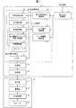
図1は、音声信号送信装置1の概略構成を示すブロック図である。音声信号送信装置1は、送信制御部14および記憶部15を備えている。送信制御部14は、句読点特定部6、音圧検出部7、音圧調整部8、再生開始タイミング特定/推定部9、時間調整部10、およびミキサー11を有している。記憶部15は、第1の音声信号格納部3、ノイズ音声格納部4、およびユーザ履歴記憶部5を有している。さらに、音声信号送信装置1は、再生指示受信部2、変調部12、および送信部13を備えている。
[Configuration of Audio Signal Transmitter]
FIG. 1 is a block diagram showing a schematic configuration of the audio signal transmitting apparatus 1. The audio signal transmission device 1 includes a transmission control unit 14 and a storage unit 15. The transmission control unit 14 includes a punctuation mark specifying unit 6, a sound pressure detecting unit 7, a sound pressure adjusting unit 8, a reproduction start timing specifying / estimating unit 9, a time adjusting unit 10, and a mixer 11. The storage unit 15 includes a first audio signal storage unit 3, a noise audio storage unit 4, and a user history storage unit 5. Furthermore, the audio signal transmitting apparatus 1 includes a reproduction instruction receiving unit 2, a modulating unit 12, and a transmitting unit 13.

再生指示受信部2は、音声信号送信装置1に対する再生指示を受信する。当該再生指示の一例として、ユーザがリモコン(図示しない)を用いて行う遠隔指示、音声信号送信装置1に設けられた再生ボタン(図示しない)をユーザが押下することによる指示、音声信号送信装置1を備えている電子機器の操作画面をユーザが操作することによる指示等が挙げられる。   The reproduction instruction receiving unit 2 receives a reproduction instruction for the audio signal transmitting apparatus 1. As an example of the reproduction instruction, a remote instruction given by the user using a remote controller (not shown), an instruction when the user presses a reproduction button (not shown) provided on the audio signal transmission apparatus 1, and the audio signal transmission apparatus 1 The instruction | indication etc. by a user operating the operation screen of the electronic device provided with are mentioned.

第1の音声信号格納部3は、第1の音声信号を格納している。第1の音声信号とは、上記再生指示に基づいて、ユーザによって再生が指示された音声であり、音楽、言葉、効果音、所定の合成音声、およびマイク(図示しない)等によってユーザが音声信号送信装置1に入力した音声等の種々の音声が挙げられる。   The first audio signal storage unit 3 stores the first audio signal. The first audio signal is an audio that is instructed to be reproduced by the user based on the above reproduction instruction, and the audio signal is transmitted by the user through music, words, sound effects, predetermined synthesized audio, a microphone (not shown), or the like. Various voices such as voice input to the transmission apparatus 1 can be mentioned.

ノイズ音声格納部4は、第2の音声信号(後述)の基となるノイズ音声を格納している。ノイズ音声とは、特定波長の連続音声、または複数の波長の音がランダムまたは一定の規則により混成された音声であることが好ましい。特定波長の連続音声の一例として、正弦波が挙げられる。複数の波長の音がランダムまたは一定の規則により混成された音声の一例として、ホワイトノイズ、ブラウンノイズ、ピンクノイズ、ブルーノイズ、又はバイオレットノイズのいずれかが挙げられる。このように、第2の音声信号に用いるノイズ音声として、種々の周知のノイズ音声を利用することができる。ノイズ音声格納部4に格納されたノイズ音声は、任意の音圧および継続時間を有していてもよい。例えば、第2の音声信号により規定される音声の音量を第1の音声信号により規定される音声の音量に対して十分小さくする場合、第1の音声信号により規定される音声の最小音量に相当する音量のノイズ音声をノイズ音声格納部4に格納しておけばよい。また、例えば、第2の音声信号により規定される音声の継続時間を10秒以下とする場合、10秒分のノイズ音声をノイズ音声格納部4に格納しておけばよい。また、上記とは別の方式として、ノイズ音声格納部に代えて、ノイズ音声発信部を設けることにより、ノイズ音声を都度合成・発信する方式を採用してもよい。   The noise sound storage unit 4 stores noise sound that is a basis of a second sound signal (described later). The noise sound is preferably a continuous sound of a specific wavelength or a sound in which sounds of a plurality of wavelengths are mixed randomly or according to a certain rule. An example of continuous sound of a specific wavelength is a sine wave. As an example of the sound in which sounds of a plurality of wavelengths are mixed randomly or according to a certain rule, there are white noise, brown noise, pink noise, blue noise, or violet noise. As described above, various known noise sounds can be used as the noise sound used for the second sound signal. The noise sound stored in the noise sound storage unit 4 may have an arbitrary sound pressure and duration. For example, when the sound volume defined by the second sound signal is sufficiently lower than the sound volume defined by the first sound signal, it corresponds to the minimum sound volume defined by the first sound signal. The noise sound having a volume to be stored may be stored in the noise sound storage unit 4. Further, for example, when the duration time of the voice defined by the second voice signal is 10 seconds or less, the noise voice for 10 seconds may be stored in the noise voice storage unit 4. Further, as a method different from the above, a method of synthesizing and transmitting noise sound each time may be adopted by providing a noise sound transmitting unit instead of the noise sound storing unit.

ユーザ履歴記憶部5は、第1の音声信号の再生履歴をはじめとする、音声信号送信装置1の各種の使用履歴および動作履歴等を記憶している。   The user history storage unit 5 stores various usage histories and operation histories of the audio signal transmission device 1 including a reproduction history of the first audio signal.

再生指示を受信すると、再生指示受信部2は、第1の音声信号格納部3に格納された第1の音声信号を、句読点特定部6に送信する。句読点特定部6は、再生対象の第1の音声信号に基づいて再生される音声から、句読点に該当するタイミングを特定する。句読点に該当するタイミングは、第1の音声信号に基づいて再生される音声が所定の長さ以上途切れる時間に相当する。   When receiving the reproduction instruction, the reproduction instruction receiving unit 2 transmits the first audio signal stored in the first audio signal storage unit 3 to the punctuation mark specifying unit 6. The punctuation mark specifying unit 6 specifies the timing corresponding to the punctuation mark from the sound reproduced based on the first audio signal to be reproduced. The timing corresponding to the punctuation mark corresponds to the time when the sound reproduced based on the first sound signal is interrupted for a predetermined length or longer.

再生指示を受信すると、再生指示受信部2は、第1の音声信号格納部3に格納された第1の音声信号を、音圧検出部7に送信する。音圧検出部7は、再生対象の第1の音声信号によって規定される音声の冒頭の音圧を検出する。一般に、当該音声の冒頭が子音である場合の音圧は、当該音声の冒頭が母音である場合の音圧より小さい傾向にある。   When the reproduction instruction is received, the reproduction instruction reception unit 2 transmits the first audio signal stored in the first audio signal storage unit 3 to the sound pressure detection unit 7. The sound pressure detection unit 7 detects the sound pressure at the beginning of the sound defined by the first sound signal to be reproduced. In general, the sound pressure when the beginning of the sound is a consonant tends to be smaller than the sound pressure when the beginning of the sound is a vowel.

再生指示を受信すると、再生指示受信部2は、ノイズ音声格納部4に格納されたノイズ音声を、音圧調整部8に送信する。また、音圧検出部7は、再生対象の第1の音声信号によって規定される音声の冒頭の音圧の検出結果を、音圧調整部8に送信する。音圧調整部8は、当該検出結果に基づいて、再生対象の第1の音声信号によって規定される音声の冒頭の音圧が小さいほど、ノイズ音声の音圧を大きくする。第1の音声信号によって規定される音声の冒頭の音圧が小さい(例えば、当該冒頭の音声が子音である)場合、第2の音声信号によって規定される音声の音圧が小さいと、第1の音声信号によって規定される音声に頭切れが生じる虞がある。音圧調整部8は、この虞を防ぐ構成であると言える。   When the reproduction instruction is received, the reproduction instruction receiving unit 2 transmits the noise sound stored in the noise sound storage unit 4 to the sound pressure adjustment unit 8. Further, the sound pressure detection unit 7 transmits the detection result of the sound pressure at the beginning of the sound defined by the first sound signal to be reproduced to the sound pressure adjustment unit 8. Based on the detection result, the sound pressure adjustment unit 8 increases the sound pressure of the noise sound as the sound pressure at the beginning of the sound defined by the first sound signal to be reproduced is smaller. When the sound pressure at the beginning of the sound defined by the first sound signal is small (for example, when the sound at the beginning is a consonant), the sound pressure of the sound defined by the second sound signal is small. There is a risk that the sound defined by the sound signal will be broken. It can be said that the sound pressure adjusting unit 8 is configured to prevent this fear.

再生指示を受信すると、再生指示受信部2は、ユーザ履歴記憶部5に記憶された各種の履歴等を、再生開始タイミング特定/推定部9に送信する。再生開始タイミング特定/推定部9は、当該履歴等に基づいて、再生対象の第1の音声信号の再生開始タイミングを事前特定または事前推定する。すなわち、再生開始タイミング特定/推定部9は、送信制御部14が第1の音声信号を送信する前に、当該再生開始タイミングを特定または推定する。   When receiving the reproduction instruction, the reproduction instruction receiving unit 2 transmits various histories and the like stored in the user history storage unit 5 to the reproduction start timing specifying / estimating unit 9. The reproduction start timing specification / estimation unit 9 specifies or pre-estimates the reproduction start timing of the first audio signal to be reproduced based on the history or the like. That is, the reproduction start timing specifying / estimating unit 9 specifies or estimates the reproduction start timing before the transmission control unit 14 transmits the first audio signal.

句読点特定部6は、再生対象の第1の音声信号に基づいて再生される音声の句読点に該当するタイミングの特定結果を、時間調整部10に送信する。また、音圧調整部8は、音圧が調整されたノイズ音声を、時間調整部10に送信する。さらに、再生開始タイミング特定/推定部9は、再生対象の第1の音声信号の再生開始タイミングの事前特定または事前推定の結果を、時間調整部10に送信する。時間調整部10は、当該句読点に該当するタイミングの特定結果ならびに当該事前特定または事前推定の結果に基づいて、ノイズ音声の再生タイミングを調整する。また、音声信号送信装置1は、時間調整部10にタイマー21を有している。時間調整部10がタイマー21を有している場合、時間調整部10は、上述したノイズ音声の再生タイミングの調整とは独立して、タイマー21がノイズ音声の再生タイミングを調整することができる。時間調整部10は、再生タイミングが調整されたノイズ音声を、第2の音声信号として出力する。   The punctuation mark specifying unit 6 transmits to the time adjustment unit 10 the result of specifying the timing corresponding to the punctuation mark of the sound reproduced based on the first audio signal to be reproduced. In addition, the sound pressure adjustment unit 8 transmits the noise sound whose sound pressure has been adjusted to the time adjustment unit 10. Further, the reproduction start timing specification / estimation unit 9 transmits the result of the prior specification or the prior estimation of the reproduction start timing of the first audio signal to be reproduced to the time adjustment unit 10. The time adjustment unit 10 adjusts the reproduction timing of the noise sound based on the result of specifying the timing corresponding to the punctuation mark and the result of the prior specification or the prior estimation. In addition, the audio signal transmission device 1 includes a timer 21 in the time adjustment unit 10. When the time adjustment unit 10 includes the timer 21, the time adjustment unit 10 can adjust the reproduction timing of the noise sound independently of the adjustment of the reproduction timing of the noise sound described above. The time adjustment unit 10 outputs the noise sound whose reproduction timing is adjusted as the second sound signal.

第2の音声信号は、ユーザによって再生が指示されていない音声信号であって、付加的な音声信号である。第2の音声信号は、第1の音声信号に基づいて再生される音声の先頭が欠けることを防止できる程度の信号強度や信号継続時間が必要であり、かつ、第1の音声信号の開始タイミングの直前に送信される必要がある。ただし、第2の音声信号によって規定される音声は、上記の条件を満足したうえで、音声が可能な限り聴取者に意識されにくい音声であることが望ましい。これは聴取者が第1の音声信号によって規定される音声を聞き取ることを阻害せず、また、聴取者に違和感を与えないためである。このため、第2の音声信号は、可能な限り強度が弱く、継続時間が短く、音声の開始タイミングを第1音声信号の開始タイミングから離すことが望ましい。ここでの意識とは聴取者がその音声を強く気にするという意味である。   The second audio signal is an audio signal that is not instructed to be reproduced by the user, and is an additional audio signal. The second audio signal needs a signal intensity and a signal duration that can prevent the beginning of the audio reproduced based on the first audio signal from being lost, and the start timing of the first audio signal Needs to be sent just before. However, it is desirable that the sound defined by the second sound signal is a sound that is as difficult as possible for the listener as much as possible after satisfying the above conditions. This is because the listener does not hinder listening to the sound defined by the first audio signal, and does not give the listener a sense of incongruity. For this reason, it is desirable that the second audio signal is as weak as possible and has a short duration, and the start timing of the audio is separated from the start timing of the first audio signal. Consciousness here means that the listener strongly cares about the sound.

また、第2の音声信号によって規定される音声が聴取者に意識されにくくするために、第2の音声信号によって規定される音声は有意でない音声であることが望ましい。ここで、有意でない音声について、以下に説明する。第1の音声信号は、例えば、何らかのメッセージや音楽など、人間の思慮、伝達情報、創作などの何らかの人間の意思を反映した有意な音声である。これに対して、第2の音声信号によって規定される音声も同じような有意な音声である場合、人間の特性として、有意な音声に反映される人間の意思により、無意識に聞き取りを行ってしまうため、聴取者に認識されやすくなってしまう。このため、第2の音声信号によって規定される音声は有意でない音声であることが望ましい。有意でない音声とは、例えば、特定波長の連続音声、または複数の波長の音がランダムまたは一定の規則により混成されたノイズ音声があげられる。上記でいう一定の規則とは、例として、複数波長それぞれの混成比率や混成の方法等についての数学的な規則などが挙げられ、人間の思慮、伝達情報、創作などの人間の意思を反映しないものである。このような有意でない音声は、聴取者にとってノイズとして認識されるため、たとえ聴取者に聞こえても意識されにくい音声である。よって、第2の音声信号によって規定される音声によって、聴取者が第1の音声信号によって規定される音声を聞き取ることを阻害されることを軽減し、また、第2の音声信号によって規定される音声が聴取者に意識されることによって、聴取者に違和感を与えることを軽減することができる。   Further, in order to make it difficult for the listener to be aware of the sound defined by the second sound signal, it is desirable that the sound defined by the second sound signal is not significant. Here, insignificant speech will be described below. The first audio signal is a significant audio that reflects some human intention such as human thought, transmission information, creation, etc., such as some message or music. On the other hand, when the voice defined by the second voice signal is also a similar significant voice, it is unintentionally heard as a human characteristic by the human intention reflected in the significant voice. Therefore, it becomes easy to be recognized by the listener. For this reason, it is desirable that the voice defined by the second voice signal is not significant. Examples of insignificant speech include continuous speech of a specific wavelength, or noise speech in which sounds of a plurality of wavelengths are mixed randomly or according to a certain rule. Examples of the certain rules mentioned above include, for example, mathematical rules for the mixing ratio and method of each of multiple wavelengths, and do not reflect human intentions such as human thought, transmission information, creation, etc. Is. Such insignificant sound is recognized as noise by the listener, and thus is difficult to recognize even if the listener can hear it. Thus, the sound defined by the second sound signal is less disturbed by the listener from listening to the sound defined by the first sound signal, and is defined by the second sound signal. By making the listener aware of the sound, it is possible to reduce the feeling of discomfort to the listener.

第2の音声信号の再生タイミング、換言すれば、時間調整部10がノイズ音声の再生タイミングを具体的にどのようなタイミングとするのかについては、後述する。   The playback timing of the second audio signal, in other words, what timing the time adjustment unit 10 uses as the playback timing of the noise audio will be described later.

再生指示を受信すると、再生指示受信部2は、第1の音声信号格納部3に格納された第1の音声信号を、ミキサー11に送信する。また、時間調整部10は、第2の音声信号を、ミキサー11に送信する。ミキサー11は、第1の音声信号と第2の音声信号とを合成し、変調部12に送信する。なお、例えば第1の音声信号の再生タイミングと第2の音声信号の再生タイミングとが大幅に異なる場合、ミキサー11を省略し、送信制御部14は、第1の音声信号と第2の音声信号とを個別に変調部12に送信してもよい。   When receiving the reproduction instruction, the reproduction instruction receiving unit 2 transmits the first audio signal stored in the first audio signal storage unit 3 to the mixer 11. In addition, the time adjustment unit 10 transmits the second audio signal to the mixer 11. The mixer 11 synthesizes the first audio signal and the second audio signal and transmits them to the modulation unit 12. For example, when the reproduction timing of the first audio signal and the reproduction timing of the second audio signal are significantly different, the mixer 11 is omitted, and the transmission control unit 14 transmits the first audio signal and the second audio signal. May be individually transmitted to the modulation unit 12.

このように、送信制御部14は、第1の音声信号を送信すると共に、第2の音声信号を自動的に送信する。   In this way, the transmission control unit 14 transmits the first audio signal and automatically transmits the second audio signal.

変調部12は、送信制御部14から送信された信号を変調し、送信部13に送信する。送信部13は、変調部12から送信された信号を、所定の送信形式に従って、音声信号として出力する。   The modulation unit 12 modulates the signal transmitted from the transmission control unit 14 and transmits the modulated signal to the transmission unit 13. The transmission unit 13 outputs the signal transmitted from the modulation unit 12 as an audio signal according to a predetermined transmission format.

音声信号送信装置1は、音声出力装置16に対して上記音声信号を送信する。なお、音声信号送信装置1および音声出力装置16においては、当該音声信号の送信を無線通信によって行っているが、当該音声信号の送信を有線通信によって行っていてもよい。   The audio signal transmission device 1 transmits the audio signal to the audio output device 16. In the audio signal transmitting apparatus 1 and the audio output apparatus 16, the audio signal is transmitted by wireless communication. However, the audio signal may be transmitted by wired communication.

音声出力装置16は、受信部17、復調部18、D/A(デジタル/アナログ)変換器19、およびスピーカ20を備えている。   The audio output device 16 includes a receiving unit 17, a demodulating unit 18, a D / A (digital / analog) converter 19, and a speaker 20.

音声信号送信装置1の送信部13は、上記音声信号を受信部17に送信する。受信部17は、送信部13から送信された音声信号を、所定の受信形式に従って受信し、復調部18に送信する。復調部18は、受信部17から送信された信号を復調し、D/A変換器19に送信する。復調部18から出力される信号は、デジタル信号である。D/A変換器19は、復調部18から送信された信号を、デジタル信号からアナログ信号に変換する。スピーカ20は、当該アナログ信号を再生し、音声を出力する。   The transmission unit 13 of the audio signal transmission device 1 transmits the audio signal to the reception unit 17. The receiving unit 17 receives the audio signal transmitted from the transmitting unit 13 according to a predetermined reception format, and transmits the audio signal to the demodulating unit 18. The demodulator 18 demodulates the signal transmitted from the receiver 17 and transmits it to the D / A converter 19. The signal output from the demodulator 18 is a digital signal. The D / A converter 19 converts the signal transmitted from the demodulator 18 from a digital signal to an analog signal. The speaker 20 reproduces the analog signal and outputs sound.

ここからは、第1の音声信号の再生タイミングおよび第2の音声信号の再生タイミングについて、下記〔実施の形態1〕〜〔実施の形態4〕を参照して、詳細な説明を行う。   From here, the reproduction timing of the first audio signal and the reproduction timing of the second audio signal will be described in detail with reference to the following [Embodiment 1] to [Embodiment 4].

〔実施の形態1〕
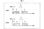
図2は、本実施の形態に係る、送信制御部14が送信する最初の第1の音声信号30、次の第1の音声信号31、および第2の音声信号32のタイミングチャート(図2中、送信時)、ならびに、受信部17が受信する最初の第1の音声信号34および次の第1の音声信号35のタイミングチャート(図2中、受信時)である。
[Embodiment 1]
2 is a timing chart of the first first audio signal 30, the next first audio signal 31, and the second audio signal 32 transmitted by the transmission control unit 14 according to the present embodiment (in FIG. 2). And at the time of transmission), and a timing chart of the first first audio signal 34 and the next first audio signal 35 received by the receiving unit 17 (at the time of reception in FIG. 2).

図2によれば、送信制御部14が送信する音声信号は、最初の第1の音声信号30の再生終了タイミングから、期間33を空けて、次の第1の音声信号31が再生される音声信号である。なお、最初の第1の音声信号30および次の第1の音声信号31は、これらの組み合わせが1つの第1の音声信号に相当していてもよいし、それぞれ別の第1の音声信号であってもよい。   According to FIG. 2, the audio signal transmitted by the transmission control unit 14 is an audio in which the next first audio signal 31 is reproduced after a period 33 from the reproduction end timing of the first first audio signal 30. Signal. Note that the combination of the first first audio signal 30 and the next first audio signal 31 may correspond to one first audio signal, or different first audio signals. There may be.

時間調整部10は、ノイズ音声の再生タイミングを調整し、最初の第1の音声信号30の再生開始に先だって、第2の音声信号32の少なくとも一部が再生されるように、第2の音声信号32を生成する。具体的に、図2においては、最初の第1の音声信号30の再生開始タイミングと第2の音声信号32の再生終了タイミングとがほぼ同じとなるように、第2の音声信号32が生成されている。   The time adjustment unit 10 adjusts the reproduction timing of the noise audio, and the second audio signal 32 is reproduced so that at least a part of the second audio signal 32 is reproduced prior to the start of the reproduction of the first first audio signal 30. A signal 32 is generated. Specifically, in FIG. 2, the second audio signal 32 is generated such that the reproduction start timing of the first first audio signal 30 and the reproduction end timing of the second audio signal 32 are substantially the same. ing.

また、図2によれば、受信部17が受信する音声信号は、最初の第1の音声信号34の再生終了タイミングから、期間37を空けて、次の第1の音声信号35が再生される音声信号である。最初の第1の音声信号34、次の第1の音声信号35、および期間37は、それぞれ、最初の第1の音声信号30、次の第1の音声信号31、および期間33と対応する。   Further, according to FIG. 2, the audio signal received by the receiving unit 17 reproduces the next first audio signal 35 after a period 37 from the reproduction end timing of the first first audio signal 34. It is an audio signal. The first first audio signal 34, the next first audio signal 35, and the period 37 correspond to the first first audio signal 30, the next first audio signal 31, and the period 33, respectively.

ここで、音声出力装置16の処理能力が不足していたり、音声出力装置16が省電力状態から復帰するまでに時間がかかることで、音声出力装置16から出力される音声の先頭が欠ける(頭切れする)場合を考える。   Here, since the processing capability of the audio output device 16 is insufficient or it takes time until the audio output device 16 returns from the power saving state, the head of the audio output from the audio output device 16 is missing (head) Think of the case.

具体的には、音声出力装置16またはスピーカ20によっては、例えば消費電力の低減を目的として、時間の長さはスピーカのタイプに大きく依存するが、例えば短いものでは1秒程度、長いものでは数十秒程度の時間音声入力が無い場合に省電力状態となるものがある。音声出力装置16またはスピーカ20が省電力状態の時に音声信号が送信された場合、音声出力装置16またはスピーカ20が動作状態に復帰するまでに時間がかかるため、音声信号の最初の部分が再生されず、頭切れの原因となる場合がある。   Specifically, depending on the audio output device 16 or the speaker 20, for example, for the purpose of reducing power consumption, the length of time greatly depends on the type of the speaker, but for example, it is about 1 second for a short one and several for a long one. There is a power saving state when there is no voice input for about ten seconds. When an audio signal is transmitted when the audio output device 16 or the speaker 20 is in the power saving state, it takes time until the audio output device 16 or the speaker 20 returns to the operation state, so that the first part of the audio signal is reproduced. In some cases, it may cause a head loss.

本発明は、特に上記の原因で発生する頭切れを解消することを念頭においている。   In particular, the present invention is intended to eliminate the head breakage caused by the above-described cause.

この場合、受信部17が受信する音声信号は、送信制御部14が送信する音声信号の先頭が欠けたものとなる。この結果、図2に示す例では、受信部17が受信する音声信号において、第2の音声信号32が消失している。図2における、第2の音声信号32の消失に対応するタイミングチャートの部分を、信号欠損部36としている。   In this case, the audio signal received by the receiving unit 17 is the audio signal transmitted by the transmission control unit 14 lacking the head. As a result, in the example illustrated in FIG. 2, the second audio signal 32 is lost in the audio signal received by the receiving unit 17. The portion of the timing chart corresponding to the disappearance of the second audio signal 32 in FIG.

一方、最初の第1の音声信号30および次の第1の音声信号31は、第2の音声信号32に対して遅れて再生されるため、受信部17が受信する音声信号において、欠けまたは消失がほとんど生じない。つまり、最初の第1の音声信号34および次の第1の音声信号35は、それぞれ、最初の第1の音声信号30および次の第1の音声信号31と同様の信号となる。また、期間37は期間33と同様の時間となる。つまり、最初の第1の音声信号30および次の第1の音声信号31に基づいてスピーカ20から出力される音声に、頭切れは生じない。立ち上がり鈍化(音量が徐々に立ち上がるよう強制的に変更される現象)についても同様に生じない。   On the other hand, since the first first audio signal 30 and the next first audio signal 31 are reproduced with a delay with respect to the second audio signal 32, the audio signal received by the receiving unit 17 is missing or lost. Hardly occurs. That is, the first first audio signal 34 and the next first audio signal 35 are the same signals as the first first audio signal 30 and the next first audio signal 31, respectively. The period 37 is the same time as the period 33. In other words, the sound output from the speaker 20 on the basis of the first first audio signal 30 and the next first audio signal 31 is not interrupted. Similarly, the rise and dullness (a phenomenon in which the volume is forcibly changed to gradually rise) does not occur.

上記の構成によれば、最初の第1の音声信号30の再生開始に先だって、第2の音声信号32を送信する。このため、音声出力装置16から出力される音声に頭切れが生じた場合、第2の音声信号32に基づいて再生される音声の先頭が欠けてしまう虞はあるものの、最初の第1の音声信号30に基づいて再生される音声の先頭が欠けてしまう虞を低減することができる。   According to the above configuration, the second audio signal 32 is transmitted prior to the start of reproduction of the first first audio signal 30. For this reason, when the sound output from the sound output device 16 is interrupted, the beginning of the sound reproduced based on the second sound signal 32 may be lost, but the first first sound may be lost. The possibility that the beginning of the sound reproduced based on the signal 30 is lost can be reduced.

また、最初の第1の音声信号30の再生に先だって付加的な音声を送信するため、原理的には最初の第1の音声信号30に対して最初の第1の音声信号34に遅延が生じない。つまり、最初の第1の音声信号30に遅延時間を設けることなく、最初の第1の音声信号30に基づいて再生される音声の頭切れを防止することができる。   Further, since the additional sound is transmitted prior to the reproduction of the first first sound signal 30, in principle, the first first sound signal 34 is delayed with respect to the first first sound signal 30. Absent. That is, it is possible to prevent the head of the audio reproduced based on the first first audio signal 30 from being cut without providing a delay time for the first first audio signal 30.

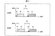
図3は、本実施の形態に係る別の、送信制御部14が送信する最初の第1の音声信号40、次の第1の音声信号41、最初の第2の音声信号42、および次の第2の音声信号43のタイミングチャート(図3中、送信時)、ならびに、受信部17が受信する最初の第1の音声信号45、次の第1の音声信号46、および次の第2の音声信号48のタイミングチャート(図3中、受信時)である。   FIG. 3 shows another first audio signal 40, the next first audio signal 41, the first second audio signal 42, and the next transmitted by the transmission control unit 14 according to the present embodiment. The timing chart of the second audio signal 43 (at the time of transmission in FIG. 3), and the first first audio signal 45, the next first audio signal 46, and the next second received by the receiving unit 17 4 is a timing chart of the audio signal 48 (at the time of reception in FIG. 3).

なお、図3における、最初の第1の音声信号40、次の第1の音声信号41、および最初の第2の音声信号42は、それぞれ、図2における、最初の第1の音声信号30、次の第1の音声信号31、および第2の音声信号32と同様の信号である。このため、最初の第1の音声信号40、次の第1の音声信号41、および最初の第2の音声信号42については、詳細な説明を省略する。   Note that the first first audio signal 40, the next first audio signal 41, and the first second audio signal 42 in FIG. 3 are the same as the first first audio signal 30 in FIG. It is the same signal as the next first audio signal 31 and second audio signal 32. Therefore, detailed description of the first first audio signal 40, the next first audio signal 41, and the first second audio signal 42 is omitted.

時間調整部10は、ノイズ音声の再生タイミングを調整し、次の第1の音声信号41の再生開始に先だって、次の第2の音声信号43の少なくとも一部が再生されるように、次の第2の音声信号43を生成する。具体的に、図3においては、次の第1の音声信号41の再生開始タイミングと次の第2の音声信号43の再生終了タイミングとがほぼ同じとなるように、次の第2の音声信号43が生成されている。   The time adjusting unit 10 adjusts the reproduction timing of the noise audio, and before the start of the reproduction of the next first audio signal 41, the time adjustment unit 10 reproduces at least a part of the next second audio signal 43. A second audio signal 43 is generated. Specifically, in FIG. 3, the next second audio signal is set so that the reproduction start timing of the next first audio signal 41 and the reproduction end timing of the next second audio signal 43 are substantially the same. 43 is generated.

また、送信制御部14が送信する音声信号は、最初の第1の音声信号40の再生終了タイミングから、期間44を空けて、次の第2の音声信号43が再生される音声信号である。   Also, the audio signal transmitted by the transmission control unit 14 is an audio signal from which the next second audio signal 43 is reproduced after a period 44 from the reproduction end timing of the first first audio signal 40.

なお、図3における、最初の第1の音声信号45、次の第1の音声信号46、および信号欠損部47は、それぞれ、図2における、最初の第1の音声信号34、次の第1の音声信号35、および信号欠損部36と同様の信号(信号の欠損)である。このため、最初の第1の音声信号45、次の第1の音声信号46、および信号欠損部47については、詳細な説明を省略する。   Note that the first first audio signal 45, the next first audio signal 46, and the signal loss unit 47 in FIG. 3 are respectively the first first audio signal 34 and the next first audio signal in FIG. Are the same signals (signal loss) as the audio signal 35 and the signal loss part 36. For this reason, detailed description of the first first audio signal 45, the next first audio signal 46, and the signal loss unit 47 is omitted.

また、図3によれば、受信部17が受信する音声信号は、最初の第1の音声信号45の再生終了タイミングから、期間49を空けて、次の第1の音声信号46が再生される音声信号である。   Further, according to FIG. 3, the audio signal received by the receiving unit 17 is reproduced with the next first audio signal 46 after a period 49 from the reproduction end timing of the first first audio signal 45. It is an audio signal.

図3に示す例においても、図2に示す例と同様に、最初の第1の音声信号40および次の第1の音声信号41に基づいてスピーカ20から出力される音声に、頭切れは生じない。   Also in the example shown in FIG. 3, as in the example shown in FIG. 2, a head break occurs in the audio output from the speaker 20 based on the first first audio signal 40 and the next first audio signal 41. Absent.

但し、期間49は、次の第2の音声信号48(次の第2の音声信号43に対応する、受信部17が受信する音声信号)の継続時間分だけ、期間44より長い時間となっている。この結果、次の第1の音声信号41に基づいてスピーカ20から出力される音声に、当該次の第2の音声信号48の継続時間分の遅延が生じることとなる。つまり、図2に示す例においては、図3に示す例と比較して、再生遅延を抑制することができるという利点がある。   However, the period 49 is longer than the period 44 by the duration of the next second audio signal 48 (the audio signal received by the receiving unit 17 corresponding to the next second audio signal 43). Yes. As a result, the audio output from the speaker 20 based on the next first audio signal 41 is delayed for the duration of the next second audio signal 48. That is, the example shown in FIG. 2 has an advantage that the reproduction delay can be suppressed as compared with the example shown in FIG.

本実施の形態は主に、音声信号送信装置1に対して最初の再生指示を行った後、次の再生指示までの時間が、音声出力装置16が省電力状態に移行するまでの時間より短いことが想定される場合に、好適に実施することができる。   In the present embodiment, after the first reproduction instruction is given to the audio signal transmitting apparatus 1, the time until the next reproduction instruction is shorter than the time until the audio output apparatus 16 shifts to the power saving state. If this is assumed, it can be suitably implemented.

〔実施の形態2〕
図4は、本実施の形態に係る、送信制御部14が送信する最初の第1の音声信号50、次の第1の音声信号51、最初の第2の音声信号52、および次の第2の音声信号53のタイミングチャート(図4中、送信時)、ならびに、受信部17が受信する最初の第1の音声信号54および次の第1の音声信号55のタイミングチャート(図4中、受信時)である。
[Embodiment 2]
FIG. 4 shows the first first audio signal 50, the next first audio signal 51, the first second audio signal 52, and the next second transmitted by the transmission control unit 14 according to the present embodiment. FIG. 4 is a timing chart of the audio signal 53 (during transmission in FIG. 4), and a timing chart of the first first audio signal 54 and the next first audio signal 55 received by the receiving unit 17 (reception in FIG. 4). Time).

なお、図4における、最初の第1の音声信号50および次の第1の音声信号51は、それぞれ、図2における、最初の第1の音声信号30および次の第1の音声信号31と同様の信号である。このため、最初の第1の音声信号50および次の第1の音声信号51については、詳細な説明を省略する。また、図4における、次の第1の音声信号51と次の第2の音声信号53との相互関係は、図2における、最初の第1の音声信号30と第2の音声信号32との相互関係と同様である。このため、次の第1の音声信号51と次の第2の音声信号53との相互関係についても、詳細な説明を省略する。   Note that the first first audio signal 50 and the next first audio signal 51 in FIG. 4 are the same as the first first audio signal 30 and the next first audio signal 31 in FIG. 2, respectively. Signal. Therefore, detailed description of the first first audio signal 50 and the next first audio signal 51 is omitted. Also, the mutual relationship between the next first audio signal 51 and the next second audio signal 53 in FIG. 4 is the same as the first first audio signal 30 and the second audio signal 32 in FIG. It is similar to the interrelationship. Therefore, detailed description of the mutual relationship between the next first audio signal 51 and the next second audio signal 53 is also omitted.

時間調整部10は、ノイズ音声の再生タイミングを調整し、最初の第1の音声信号50の再生開始に先だって、最初の第2の音声信号52の少なくとも一部が再生されるように、最初の第2の音声信号52を生成する。具体的に、図4においては、最初の第1の音声信号50の再生開始タイミングに対して一定の期間5Aだけ前に、最初の第2の音声信号52の再生終了タイミングが来るように、最初の第2の音声信号52が生成されている。期間5Aに相当する時間は、特に限定されないが、1秒未満であれば、再生遅延をできるだけ抑制しつつ、最初の第1の音声信号50に基づいてスピーカ20から出力される音声に、頭切れが生じることを抑制することができる。   The time adjustment unit 10 adjusts the reproduction timing of the noise audio, and before the start of the reproduction of the first first audio signal 50, the time adjustment unit 10 reproduces at least a part of the first second audio signal 52. A second audio signal 52 is generated. Specifically, in FIG. 4, the reproduction end timing of the first second audio signal 52 comes before the predetermined period 5A before the reproduction start timing of the first first audio signal 50. The second audio signal 52 is generated. The time corresponding to the period 5A is not particularly limited, but if it is less than 1 second, the sound output from the speaker 20 based on the first first audio signal 50 is cut off while suppressing the reproduction delay as much as possible. Can be prevented from occurring.

なお、最初の第2の音声信号52は、送信制御部14によって、最初の第1の音声信号50の再生開始前に適切なタイミングで送信されている。再生開始タイミング特定/推定部9による上述した事前特定または事前推定の結果を参照すれば、時間調整部10は、容易に、最初の第1の音声信号50の再生開始前に最初の第2の音声信号52が適切なタイミングで送信されるように、ノイズ音声の再生タイミングを調整することができる。   The first second audio signal 52 is transmitted by the transmission control unit 14 at an appropriate timing before the reproduction of the first first audio signal 50 is started. With reference to the result of the prior specification or prior estimation described above by the reproduction start timing specification / estimation unit 9, the time adjustment unit 10 can easily perform the first second before the start of reproduction of the first first audio signal 50. The reproduction timing of the noise audio can be adjusted so that the audio signal 52 is transmitted at an appropriate timing.

なお、図4における、最初の第1の音声信号54および次の第1の音声信号55は、それぞれ、図2における、最初の第1の音声信号34および次の第1の音声信号35と同様の信号である。このため、最初の第1の音声信号54および次の第1の音声信号55については、詳細な説明を省略する。   Note that the first first audio signal 54 and the next first audio signal 55 in FIG. 4 are the same as the first first audio signal 34 and the next first audio signal 35 in FIG. 2, respectively. Signal. For this reason, detailed description of the first first audio signal 54 and the next first audio signal 55 is omitted.

また、図4中、受信時は、受信部17が最初の第1の音声信号54を受信した後、音声出力装置16が省電力状態に移行することを想定している。   In FIG. 4, it is assumed that the audio output device 16 shifts to the power saving state after the reception unit 17 receives the first first audio signal 54 during reception.

受信部17が受信する音声信号は、最初の第1の音声信号54の再生および次の第1の音声信号55の再生のそれぞれについて、送信制御部14が送信する音声信号の先頭が欠けたものとなる。この結果、図4に示す例では、受信部17が受信する音声信号において、最初の第2の音声信号52および次の第2の音声信号53が消失している。図4における、最初の第2の音声信号52の消失に対応するタイミングチャートの部分、および次の第2の音声信号53の消失に対応するタイミングチャートの部分を、それぞれ、信号欠損部56および信号欠損部57としている。   The audio signal received by the receiving unit 17 lacks the beginning of the audio signal transmitted by the transmission control unit 14 for each of the reproduction of the first first audio signal 54 and the reproduction of the next first audio signal 55. It becomes. As a result, in the example shown in FIG. 4, the first second audio signal 52 and the next second audio signal 53 are lost in the audio signal received by the receiving unit 17. The portion of the timing chart corresponding to the disappearance of the first second audio signal 52 and the portion of the timing chart corresponding to the disappearance of the next second audio signal 53 in FIG. The defect portion 57 is used.

一方、最初の第1の音声信号50および次の第1の音声信号51は、それぞれ最初の第2の音声信号52および次の第2の音声信号53に対して遅れて再生されるため、受信部17が受信する音声信号において、欠けまたは消失がほとんど生じない。つまり、最初の第1の音声信号54および次の第1の音声信号55は、それぞれ、最初の第1の音声信号50および次の第1の音声信号51と同様の信号となる。つまり、最初の第1の音声信号50および次の第1の音声信号51に基づいてスピーカ20から出力される音声に、頭切れは生じない。   On the other hand, the first first audio signal 50 and the next first audio signal 51 are reproduced with a delay from the first second audio signal 52 and the next second audio signal 53, respectively. The audio signal received by the unit 17 is hardly missing or lost. That is, the first first audio signal 54 and the next first audio signal 55 are the same signals as the first first audio signal 50 and the next first audio signal 51, respectively. In other words, the sound output from the speaker 20 on the basis of the first first audio signal 50 and the next first audio signal 51 is not interrupted.

また、図4においては、送信制御部14から受信部17への音声信号の伝達に伴う、最初の第1の音声信号50に対する最初の第1の音声信号54の遅延時間を、期間58とし、次の第1の音声信号51に対する次の第1の音声信号55の遅延時間を、期間59としている。   In FIG. 4, the delay time of the first first audio signal 54 with respect to the first first audio signal 50 accompanying the transmission of the audio signal from the transmission control unit 14 to the receiving unit 17 is a period 58. A delay time of the next first audio signal 55 with respect to the next first audio signal 51 is a period 59.

期間59は、期間58より長くなっている。つまり、次の第1の音声信号51に基づいてスピーカ20から出力される音声に生じる遅延は、最初の第1の音声信号50に基づいてスピーカ20から出力される音声に生じる遅延より大きくなっている。   The period 59 is longer than the period 58. That is, the delay generated in the sound output from the speaker 20 based on the next first audio signal 51 is larger than the delay generated in the sound output from the speaker 20 based on the first first audio signal 50. Yes.

〔実施の形態3〕
図5は、本実施の形態に係る、送信制御部14が送信する最初の第1の音声信号60、次の第1の音声信号61、最初の第2の音声信号62、および次の第2の音声信号63のタイミングチャート(図5中、送信時)、ならびに、受信部17が受信する最初の第1の音声信号64、次の第1の音声信号65、および次の第2の音声信号67のタイミングチャート(図5中、受信時)である。
[Embodiment 3]
FIG. 5 shows the first first audio signal 60, the next first audio signal 61, the first second audio signal 62, and the next second transmitted by the transmission control unit 14 according to the present embodiment. The timing chart of the audio signal 63 (at the time of transmission in FIG. 5), and the first first audio signal 64, the next first audio signal 65, and the next second audio signal received by the receiving unit 17 67 is a timing chart of 67 (at the time of reception in FIG. 5).

なお、図5における、最初の第1の音声信号60および最初の第2の音声信号62は、それぞれ、図4における、最初の第1の音声信号50および最初の第2の音声信号52と同様の信号である。このため、最初の第1の音声信号60および最初の第2の音声信号62については、詳細な説明を省略する。また、図5における、次の第1の音声信号61および次の第2の音声信号63も、それぞれ、図4における、最初の第1の音声信号50および最初の第2の音声信号52と同様の信号である。このため、次の第1の音声信号61および次の第2の音声信号63についても、詳細な説明を省略する。   Note that the first first audio signal 60 and the first second audio signal 62 in FIG. 5 are the same as the first first audio signal 50 and the first second audio signal 52 in FIG. 4, respectively. Signal. Therefore, detailed description of the first first audio signal 60 and the first second audio signal 62 is omitted. Also, the next first audio signal 61 and the next second audio signal 63 in FIG. 5 are the same as the first first audio signal 50 and the first second audio signal 52 in FIG. 4, respectively. Signal. Therefore, detailed description of the next first audio signal 61 and the next second audio signal 63 is also omitted.

図5においては、図4と同様に、最初の第1の音声信号60の再生開始タイミングに対して一定の期間6Aだけ前に、最初の第2の音声信号62の再生終了タイミングが来るように、最初の第2の音声信号62が生成されている。期間6Aに相当する時間は、特に限定されないが、1秒未満であれば、再生遅延をできるだけ抑制しつつ、最初の第1の音声信号60に基づいてスピーカ20から出力される音声に、頭切れが生じることを抑制することができる。換言すれば、送信制御部14は、最初の第1の音声信号60の再生開始1秒前以内に最初の第2の音声信号62の少なくとも一部を再生させることが好ましい。   In FIG. 5, similarly to FIG. 4, the reproduction end timing of the first second audio signal 62 comes before a certain period 6 </ b> A before the reproduction start timing of the first first audio signal 60. The first second audio signal 62 is generated. The time corresponding to the period 6A is not particularly limited, but if it is less than 1 second, the sound output from the speaker 20 based on the first first audio signal 60 is cut off while suppressing the reproduction delay as much as possible. Can be prevented from occurring. In other words, the transmission control unit 14 preferably reproduces at least a part of the first second audio signal 62 within one second before the start of reproduction of the first first audio signal 60.

また、最初の第2の音声信号62の再生開始タイミング(例えば、アプリ起動のタイミング)と、次の第2の音声信号63の再生開始タイミングとの間隔に相当する期間6Bは、予め定められた一定の時間となっている。期間6Bに相当する時間は、特に限定されないが、音声出力装置16が省電力状態に移行するまでの時間未満とすることが好ましく、例えば数10秒〜数分であることが好ましい。また、期間6Bに相当する最適な時間は、音声出力装置16の種類や、ユーザの感覚によって異なるので、ユーザが期間6Bに相当する時間を任意に調整することができるように、音声信号送信装置1が構成されていることが好ましい。   A period 6B corresponding to the interval between the reproduction start timing of the first second audio signal 62 (for example, the application activation timing) and the reproduction start timing of the next second audio signal 63 is determined in advance. It is a certain time. The time corresponding to the period 6B is not particularly limited, but is preferably less than the time until the audio output device 16 shifts to the power saving state, and is preferably, for example, several tens of seconds to several minutes. Moreover, since the optimal time corresponding to the period 6B varies depending on the type of the audio output device 16 and the user's feeling, the audio signal transmitting apparatus can be adjusted arbitrarily by the user. 1 is preferably configured.

なお、図5における、最初の第1の音声信号64および信号欠損部66は、それぞれ、図4における、最初の第1の音声信号54および信号欠損部56と同様の信号(信号の欠損)である。このため、最初の第1の音声信号64および信号欠損部66については、詳細な説明を省略する。   Note that the first first audio signal 64 and the signal loss portion 66 in FIG. 5 are the same signals (signal loss) as the first first audio signal 54 and the signal loss portion 56 in FIG. 4, respectively. is there. For this reason, detailed description of the first first audio signal 64 and the signal loss unit 66 is omitted.

また、図5における、次の第2の音声信号67は、次の第2の音声信号63に対応する、受信部17が受信する音声信号である。   Further, the next second audio signal 67 in FIG. 5 is an audio signal received by the receiving unit 17 corresponding to the next second audio signal 63.

〔実施の形態4〕
送信制御部14は、少なくとも1つの第1の音声信号に基づいて再生される音声が途切れる時間が所定の長さ以上であるとき、この時間の少なくとも一部において第2の音声信号が再生されるように、第2の音声信号を送信してもよい。句読点特定部6による上述した句読点に該当するタイミングの特定結果を参照すれば、時間調整部10は、容易に、当該第2の音声信号の送信を実現するように、ノイズ音声の再生タイミングを調整することができる。
[Embodiment 4]
The transmission control unit 14 reproduces the second audio signal during at least a part of the time when the sound to be reproduced based on at least one first audio signal is interrupted for a predetermined length or longer. As described above, the second audio signal may be transmitted. By referring to the result of specifying the timing corresponding to the punctuation mark described above by the punctuation mark specifying unit 6, the time adjustment unit 10 easily adjusts the reproduction timing of the noise sound so as to realize the transmission of the second audio signal. can do.

上記の構成によれば、第1の音声信号によって規定される音声に句読点(音声が途切れる)が含まれている場合であっても、当該句読点のタイミングにおいて音声出力装置16が省電力状態に移行することを防ぐことができる。これにより、句読点の後の音声に頭切れが生じることを防ぐ効果を奏する。   According to the configuration described above, even if the sound defined by the first sound signal includes punctuation marks (the sound is interrupted), the sound output device 16 shifts to the power saving state at the timing of the punctuation marks. Can be prevented. As a result, there is an effect of preventing the head after the punctuation mark from being cut off.

音声信号送信装置1は、ノイズ音声格納部4に複数種類のノイズ音声が格納されており、当該複数種類のノイズ音声から、ユーザが第2の音声信号の基とすべきノイズ音声を選択することができるように構成されていてもよい。また、音声信号送信装置1は、当該複数種類のノイズ音声から、ユーザが第2の音声信号の基とすべきノイズ音声を選択することができないように構成されていてもよいし、そもそもノイズ音声格納部4に1種類のノイズ音声のみが格納されていてもよい。   The audio signal transmitting apparatus 1 stores a plurality of types of noise audio in the noise audio storage unit 4, and the user selects a noise audio to be used as a basis for the second audio signal from the plurality of types of noise audio. It may be configured to be able to. The audio signal transmitting apparatus 1 may be configured such that the user cannot select the noise audio that should be the basis of the second audio signal from the plurality of types of noise audio, or the noise audio in the first place. Only one type of noise sound may be stored in the storage unit 4.

また、上記の各実施の形態においては、第1の音声信号と第2の音声信号とが重なり合っていなかったが、第1の音声信号と第2の音声信号とが重なり合っていてもよい。   Further, in each of the above embodiments, the first audio signal and the second audio signal do not overlap, but the first audio signal and the second audio signal may overlap.

〔音声信号送信装置の動作の流れの一例〕
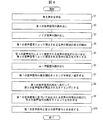
図6は、音声信号送信装置1の動作(音声信号送信方法)の流れの一例を示すフローチャートである。
[Example of operation flow of audio signal transmitting apparatus]
FIG. 6 is a flowchart illustrating an example of the flow of the operation (audio signal transmission method) of the audio signal transmission apparatus 1.

まず、再生指示受信部2が再生指示を受信する(ステップS1)。   First, the reproduction instruction receiving unit 2 receives a reproduction instruction (step S1).

続いて、第1の音声信号の読み出しを行う(ステップS2)。具体的に、再生指示受信部2は、第1の音声信号格納部3に格納された第1の音声信号を、句読点特定部6、音圧検出部7、およびミキサー11に送信する。   Subsequently, the first audio signal is read (step S2). Specifically, the reproduction instruction receiving unit 2 transmits the first audio signal stored in the first audio signal storage unit 3 to the punctuation mark specifying unit 6, the sound pressure detection unit 7, and the mixer 11.

続いて、ノイズ音声の読み出しを行う(ステップS3)。具体的に、再生指示受信部2は、ノイズ音声格納部4に格納されたノイズ音声を、音圧調整部8に送信する。   Subsequently, the noise sound is read (step S3). Specifically, the reproduction instruction receiving unit 2 transmits the noise sound stored in the noise sound storage unit 4 to the sound pressure adjustment unit 8.

続いて、音圧検出部7は、第1の音声信号によって規定される音声の冒頭の音圧を検出する(ステップS4)。   Subsequently, the sound pressure detection unit 7 detects the beginning sound pressure of the sound defined by the first sound signal (step S4).

続いて、音圧調整部8は、音圧検出部7による音圧の検出結果に基づいて、第1の音声信号によって規定される音声の冒頭の音圧が小さいほど、第2の音声信号によって規定される音声の音圧を大きくするように、ノイズ音声の音圧を調整する(ステップS5)。   Subsequently, based on the detection result of the sound pressure by the sound pressure detection unit 7, the sound pressure adjustment unit 8 uses the second sound signal as the sound pressure at the beginning of the sound defined by the first sound signal is smaller. The sound pressure of the noise sound is adjusted so as to increase the sound pressure of the specified sound (step S5).

続いて、ユーザ履歴の読み出しを行う(ステップS6)。具体的に、再生指示受信部2は、ユーザ履歴記憶部5に記憶された、音声信号送信装置1の各種の使用履歴および動作履歴等を、再生開始タイミング特定/推定部9に送信する。   Subsequently, the user history is read (step S6). Specifically, the reproduction instruction receiving unit 2 transmits various usage histories and operation histories of the audio signal transmission device 1 stored in the user history storage unit 5 to the reproduction start timing specifying / estimating unit 9.

続いて、再生開始タイミング特定/推定部9は、第1の音声信号の再生開始タイミングを特定または推定する(ステップS7)。   Subsequently, the reproduction start timing specifying / estimating unit 9 specifies or estimates the reproduction start timing of the first audio signal (step S7).

続いて、時間調整部10は、第1の音声信号の再生開始に先だって、第2の音声信号の少なくとも一部が再生されるタイミングにする(ステップS8:送信制御工程)。具体的に、時間調整部10は、音圧調整部8より受信したノイズ音声の再生タイミングを調整することによって、第2の音声信号の再生タイミングを調整する。   Subsequently, the time adjustment unit 10 sets the timing at which at least a part of the second audio signal is reproduced prior to the start of reproduction of the first audio signal (step S8: transmission control step). Specifically, the time adjustment unit 10 adjusts the reproduction timing of the second audio signal by adjusting the reproduction timing of the noise audio received from the sound pressure adjustment unit 8.

続いて、時間調整部10は、句読点特定部6による句読点に該当するタイミングの特定結果に基づいて、第1の音声信号に基づいて再生される音声の句読点に該当するタイミングに、第2の音声信号の再生タイミングを合わせる(ステップS9)。ステップS8と同様に、時間調整部10は、音圧調整部8より受信したノイズ音声の再生タイミングを調整することによって、第2の音声信号の再生タイミングを調整する。   Subsequently, the time adjustment unit 10 determines the second voice at the timing corresponding to the punctuation mark of the voice reproduced based on the first voice signal, based on the specification result of the timing corresponding to the punctuation mark by the punctuation mark specifying unit 6. The signal reproduction timing is matched (step S9). Similar to step S8, the time adjustment unit 10 adjusts the reproduction timing of the second audio signal by adjusting the reproduction timing of the noise audio received from the sound pressure adjustment unit 8.

最後に、ミキサー11は、第1の音声信号と第2の音声信号とを合成する(ステップS10)。   Finally, the mixer 11 synthesizes the first audio signal and the second audio signal (step S10).

なお、音声信号送信装置1において、必須の動作は、ステップS1〜ステップS3、およびステップS8である。その他の各ステップについては、適宜省略されてもよいし、順序が適宜変更されてもよい。   In the audio signal transmitting apparatus 1, essential operations are step S1 to step S3 and step S8. About each other step, it may be abbreviate | omitted suitably and the order may be changed suitably.

〔実施の形態5〕
図7は、本実施の形態に係るスマートフォン70およびぬいぐるみ71(電子機器)の概略構成を示す図である。図7に示すスマートフォン70は、音声信号送信装置1(図1参照)を備えている。また、図7に示すぬいぐるみ71は、音声出力装置16(図1参照)を備えている。
[Embodiment 5]
FIG. 7 is a diagram illustrating a schematic configuration of the smartphone 70 and the stuffed toy 71 (electronic device) according to the present embodiment. A smartphone 70 illustrated in FIG. 7 includes the audio signal transmission device 1 (see FIG. 1). Moreover, the stuffed toy 71 shown in FIG. 7 includes the audio output device 16 (see FIG. 1).

ユーザである操作者(ここでは親)は、スマートフォン70の操作画面72から、再生すべき音声(第1の音声信号に基づいて再生される音声)を選択し、スマートフォン70の音声信号送信装置1に対する再生指示を行う。これにより、ぬいぐるみ71の音声出力装置16のスピーカ20から、頭切れの無い当該音声を出力させることができる。操作者が場面に応じて複数の当該音声を使い分けることで、聴取者(ここでは子供)に対してあたかもぬいぐるみ71と会話しているかのような感覚を与えることができる。   The operator (here, the parent) who is the user selects the sound to be reproduced (the sound reproduced based on the first audio signal) from the operation screen 72 of the smartphone 70, and the audio signal transmission device 1 of the smartphone 70. Is instructed to play. Thereby, the said audio | voice without a head can be output from the speaker 20 of the audio | voice output apparatus 16 of the stuffed toy 71. FIG. The operator can use a plurality of sounds according to the scene, so that the listener (here, a child) can feel as if he / she is talking to the stuffed toy 71.

最初の第1の音声信号に基づいて再生される音声の頭切れを防ぎ、かつ聴取者の反応に対して遅延無く、次の第1の音声信号に基づいて再生される音声を再生させることで、聴取者とぬいぐるみ71との対話を円滑に演出することができる。   By preventing the head of the audio reproduced based on the first first audio signal from being cut off and reproducing the audio reproduced based on the next first audio signal without delay with respect to the listener's reaction. The dialogue between the listener and the stuffed toy 71 can be smoothly produced.

図8は、本実施の形態に係る別のスマートフォン80およびぬいぐるみ81(電子機器)の概略構成を示す図である。図8に示すスマートフォン80は、図7に示すスマートフォン70の構成に加え、音声出力装置16を備えている。また、図8に示すぬいぐるみ81は、図7に示すぬいぐるみ71の構成に加え、音声信号送信装置1を備えている。スマートフォン80の音声信号送信装置1とぬいぐるみ81の音声出力装置16とで、1つの通信系統が構成されていると共に、スマートフォン80の音声出力装置16とぬいぐるみ81の音声信号送信装置1とで、別の1つの通信系統が構成されている。   FIG. 8 is a diagram showing a schematic configuration of another smartphone 80 and a stuffed toy 81 (electronic device) according to the present embodiment. A smartphone 80 illustrated in FIG. 8 includes an audio output device 16 in addition to the configuration of the smartphone 70 illustrated in FIG. 7. A stuffed animal 81 shown in FIG. 8 includes an audio signal transmitting device 1 in addition to the configuration of the stuffed animal 71 shown in FIG. The audio signal transmitting device 1 of the smartphone 80 and the audio output device 16 of the stuffed toy 81 constitute one communication system, and the audio output device 16 of the smartphone 80 and the audio signal transmitting device 1 of the stuffed toy 81 are different. One communication system is configured.

スマートフォン80およびぬいぐるみ81において、上記別の1つの通信系統を構成し、スマートフォン80の音声出力装置16を介して操作者が例えばイヤホン83を用いて聴取者の声を聴く。これにより、聴取者から離れた場所(聴取者の居る部屋とは別の部屋等)から、操作者と聴取者とが会話を行うことができる。すなわち、下記(1)〜(5)の流れで、当該会話が可能となる。
(1)スマートフォン80の操作画面82から、操作者が再生すべき音声を選択する。
(2)ぬいぐるみ81が発声(音声を出力)する。
(3)ぬいぐるみ81の発声に応じて、聴取者が返答する。
(4)上記(3)の返答を再生すべき音声として、ぬいぐるみ81からスマートフォン80に音声信号を送信する。
(5)操作者がイヤホン83を用いて、上記(4)の音声信号に基づいて再生される音声を聴く。
In the smartphone 80 and the stuffed toy 81, another communication system is configured, and the operator listens to the listener's voice using, for example, the earphone 83 via the audio output device 16 of the smartphone 80. Thereby, the operator and the listener can have a conversation from a place away from the listener (a room other than the room where the listener is present). That is, the conversation can be performed according to the following flows (1) to (5).
(1) From the operation screen 82 of the smartphone 80, the voice to be reproduced by the operator is selected.
(2) The stuffed toy 81 utters (outputs voice).
(3) The listener responds in response to the utterance of the stuffed toy 81.
(4) A voice signal is transmitted from the stuffed toy 81 to the smartphone 80 as the voice to be played back as the reply in (3) above.
(5) The operator uses the earphone 83 to listen to the sound reproduced based on the sound signal of (4).

〔実施の形態6〕
図9は、本実施の形態に係るスマートフォン90およびヘッドホン91(電子機器)の概略構成を示す図である。図9に示すスマートフォン90は、音声信号送信装置1(図1参照)を備えている。また、図9に示すヘッドホン91は、音声出力装置16(図1参照)を備えており、スマートフォン90の音声信号送信装置1と無線通信を行う、いわゆる無線ヘッドホンである。
[Embodiment 6]
FIG. 9 is a diagram showing a schematic configuration of the smartphone 90 and the headphone 91 (electronic device) according to the present embodiment. A smartphone 90 shown in FIG. 9 includes an audio signal transmission device 1 (see FIG. 1). Moreover, the headphones 91 shown in FIG. 9 are so-called wireless headphones that include the audio output device 16 (see FIG. 1) and perform wireless communication with the audio signal transmission device 1 of the smartphone 90.

スマートフォン90およびヘッドホン91によれば、スマートフォン90に格納された音楽(第1の音声信号に基づいて再生される音声)をヘッドホン91から出力する。これにより、ヘッドホン91から出力される当該音楽の頭切れを防ぐことができる。   According to the smartphone 90 and the headphones 91, music stored in the smartphone 90 (sound reproduced based on the first audio signal) is output from the headphones 91. Thereby, the head of the music output from the headphones 91 can be prevented from being cut off.

〔実施の形態7〕
図10は、本実施の形態に係るスマートフォン100およびヘッドセット101(電子機器)の概略構成を示す図である。図10に示すスマートフォン100は、音声信号送信装置1(図1参照)および音声出力装置16(図1参照)を備えている。また、図10に示すヘッドセット101も、音声信号送信装置1および音声出力装置16を備えている。スマートフォン100の音声信号送信装置1とヘッドセット101の音声出力装置16とで、1つの通信系統が構成されていると共に、スマートフォン100の音声出力装置16とヘッドセット101の音声信号送信装置1とで、別の1つの通信系統が構成されている。なお、図10に示すヘッドセット101は、スマートフォン100の音声信号送信装置1および音声出力装置16と無線通信を行う、いわゆる無線ヘッドセットである。
[Embodiment 7]
FIG. 10 is a diagram illustrating a schematic configuration of the smartphone 100 and the headset 101 (electronic device) according to the present embodiment. A smartphone 100 shown in FIG. 10 includes an audio signal transmission device 1 (see FIG. 1) and an audio output device 16 (see FIG. 1). The headset 101 shown in FIG. 10 also includes the audio signal transmission device 1 and the audio output device 16. The audio signal transmission device 1 of the smartphone 100 and the audio output device 16 of the headset 101 constitute one communication system, and the audio output device 16 of the smartphone 100 and the audio signal transmission device 1 of the headset 101 Another communication system is configured. A headset 101 illustrated in FIG. 10 is a so-called wireless headset that performs wireless communication with the audio signal transmission device 1 and the audio output device 16 of the smartphone 100.

スマートフォン100およびヘッドセット101によれば、スマートフォン100による通話時において、ヘッドセット101を利用して通話相手の声を聴いたり、ヘッドセット101のマイクで通話相手に声を送信したりすることができる。   According to the smartphone 100 and the headset 101, at the time of a call by the smartphone 100, the headset 101 can be used to listen to the other party's voice, or the headset 101 microphone can be used to transmit the voice to the other party. .

〔ソフトウェアによる実現例〕
音声信号送信装置1の制御ブロック(特に送信制御部14)は、集積回路(ICチップ)等に形成された論理回路(ハードウェア)によって実現してもよいし、CPU(Central Processing Unit)を用いてソフトウェアによって実現してもよい。
[Example of software implementation]
The control block (particularly the transmission control unit 14) of the audio signal transmitting apparatus 1 may be realized by a logic circuit (hardware) formed in an integrated circuit (IC chip) or the like, or using a CPU (Central Processing Unit). It may be realized by software.

後者の場合、音声信号送信装置1は、各機能を実現するソフトウェアであるプログラムの命令を実行するCPU、上記プログラムおよび各種データがコンピュータ(またはCPU)で読み取り可能に記録されたROM(Read Only Memory)または記憶装置(これらを「記録媒体」と称する)、上記プログラムを展開するRAM(Random Access Memory)などを備えている。そして、コンピュータ(またはCPU)が上記プログラムを上記記録媒体から読み取って実行することにより、本発明の目的が達成される。上記記録媒体としては、「一時的でない有形の媒体」、例えば、テープ、ディスク、カード、半導体メモリ、プログラマブルな論理回路などを用いることができる。また、上記プログラムは、該プログラムを伝送可能な任意の伝送媒体(通信ネットワークや放送波等)を介して上記コンピュータに供給されてもよい。なお、本発明は、上記プログラムが電子的な伝送によって具現化された、搬送波に埋め込まれたデータ信号の形態でも実現され得る。   In the latter case, the audio signal transmitting apparatus 1 includes a CPU that executes instructions of a program that is software that realizes each function, and a ROM (Read Only Memory) in which the program and various data are recorded so as to be readable by a computer (or CPU). ) Or a storage device (these are referred to as “recording media”), a RAM (Random Access Memory) for expanding the program, and the like. And the objective of this invention is achieved when a computer (or CPU) reads the said program from the said recording medium and runs it. As the recording medium, a “non-temporary tangible medium” such as a tape, a disk, a card, a semiconductor memory, a programmable logic circuit, or the like can be used. The program may be supplied to the computer via an arbitrary transmission medium (such as a communication network or a broadcast wave) that can transmit the program. The present invention can also be realized in the form of a data signal embedded in a carrier wave in which the program is embodied by electronic transmission.

〔まとめ〕
本発明の態様1に係る音声信号送信装置1は、音声出力装置16に対して音声信号を送信する装置であって、ユーザによって再生が指示された第1の音声信号を送信するとともに、前記第1の音声信号の再生開始に先だって、ユーザによって再生が指示されていない音声信号であって、付加的な音声信号である第2の音声信号の少なくとも一部が再生されるように、前記第2の音声信号を自動的に送信する送信制御部14を備えている。
[Summary]
The audio signal transmitting apparatus 1 according to the first aspect of the present invention is an apparatus that transmits an audio signal to the audio output apparatus 16, and transmits a first audio signal that is instructed to be reproduced by a user. Prior to the start of reproduction of the first audio signal, the second audio signal is reproduced so that at least a part of the second audio signal which is an additional audio signal that is not instructed to be reproduced by the user is reproduced. The transmission control unit 14 for automatically transmitting the audio signal is provided.

上記の構成によれば、第1の音声信号の再生開始に先だって、第2の音声信号を送信する。このため、音声出力装置から出力される音声に頭切れが生じた場合、第2の音声信号に基づいて再生される音声の先頭が欠けてしまう虞はあるものの、第1の音声信号に基づいて再生される音声の先頭が欠けてしまう虞を低減することができる。   According to the above configuration, the second audio signal is transmitted prior to the start of reproduction of the first audio signal. For this reason, when the sound output from the sound output device is interrupted, there is a possibility that the head of the sound reproduced based on the second sound signal may be lost, but based on the first sound signal. It is possible to reduce the possibility that the beginning of the reproduced audio is lost.

また、上記の構成によれば、第1の音声信号の再生に先だって付加的な音声を送信するため、原理的には第1の音声信号に遅延が生じない。つまり、第1の音声信号に遅延時間を設けることなく、第1の音声信号に基づいて再生される音声の頭切れを防止することができる。   In addition, according to the above configuration, since the additional sound is transmitted prior to the reproduction of the first sound signal, there is no delay in the first sound signal in principle. That is, it is possible to prevent the head of the audio reproduced based on the first audio signal from being cut off without providing a delay time for the first audio signal.

本発明の態様2に係る音声信号送信装置1は、上記態様1において、前記第2の音声信号は、特定波長の連続音声、または複数の波長の音がランダムまたは一定の規則により混成されたノイズ音声を含む。   The sound signal transmitting apparatus 1 according to aspect 2 of the present invention is the sound signal transmitting apparatus 1 according to aspect 1, wherein the second sound signal is a continuous sound of a specific wavelength or a noise in which sounds of a plurality of wavelengths are mixed according to a random or constant rule. Includes audio.

上記の構成によれば、第2の音声信号によって規定される音声によって、聴取者が第1の音声信号によって規定される音声を聞き取ることを阻害されることを軽減し、また、第2の音声信号によって規定される音声が聴取者に意識されることによって、聴取者に違和感を与えることを軽減することができる。   According to the above configuration, the sound defined by the second sound signal can be reduced to prevent the listener from hearing the sound defined by the first sound signal, and the second sound can be reduced. Since the listener is aware of the sound defined by the signal, it is possible to reduce the feeling of discomfort to the listener.

本発明の態様3に係る音声信号送信装置1は、上記態様2において、前記ノイズ音声は、ホワイトノイズ、ブラウンノイズ、ピンクノイズ、ブルーノイズ、又はバイオレットノイズのいずれかである。   In the audio signal transmitting apparatus 1 according to aspect 3 of the present invention, in the above aspect 2, the noise sound is any of white noise, brown noise, pink noise, blue noise, or violet noise.

上記の構成によれば、第2の音声信号に用いるノイズ音声として、種々の周知のノイズ音声を利用することができる。   According to said structure, various known noise audio | voices can be utilized as a noise audio | voice used for a 2nd audio | voice signal.

本発明の態様4に係る音声信号送信装置1は、上記態様1から3のいずれかにおいて、前記送信制御部14は、前記第1の音声信号の再生開始1秒前以内に前記第2の音声信号の少なくとも一部を再生させる。   The audio signal transmitting apparatus 1 according to aspect 4 of the present invention is the audio signal transmitting apparatus 1 according to any one of the above aspects 1 to 3, wherein the transmission control unit 14 includes the second audio within one second before the start of reproduction of the first audio signal. Play at least part of the signal.

上記の構成によれば、再生遅延をできるだけ抑制しつつ、第1の音声信号に基づいて再生される音声に、頭切れが生じることを抑制することができる。   According to the above configuration, it is possible to suppress a head break in the audio reproduced based on the first audio signal while suppressing the reproduction delay as much as possible.

本発明の態様5に係る音声信号送信装置1は、上記態様1から4のいずれかにおいて、前記送信制御部14は、前記第1の音声信号によって規定される音声の冒頭の音圧が小さいほど、前記第2の音声信号によって規定される音声の音圧が大きくなるように生成された、前記第2の音声信号を送信する。   The sound signal transmitting apparatus 1 according to aspect 5 of the present invention is the sound signal transmitting apparatus 1 according to any one of the above aspects 1 to 4, wherein the transmission control unit 14 decreases the sound pressure at the beginning of the sound defined by the first sound signal. The second sound signal generated so that the sound pressure of the sound defined by the second sound signal is increased is transmitted.

第1の音声信号によって規定される音声の冒頭の音圧が小さい(例えば、当該冒頭の音声が子音である)場合、第2の音声信号によって規定される音声の音圧が小さいと、第1の音声信号によって規定される音声に頭切れが生じる虞がある。上記の構成によれば、この虞を防ぐ効果を奏する。   When the sound pressure at the beginning of the sound defined by the first sound signal is small (for example, when the sound at the beginning is a consonant), the sound pressure of the sound defined by the second sound signal is small. There is a risk that the sound defined by the sound signal will be broken. According to said structure, there exists an effect which prevents this fear.

本発明の態様6に係る音声信号送信装置1は、上記態様1から5のいずれかにおいて、前記送信制御部14は、前記第1の音声信号の再生開始タイミングを前記第1の音声信号の送信前に事前特定または事前推定する。   In the audio signal transmitting apparatus 1 according to aspect 6 of the present invention, in any one of the above aspects 1 to 5, the transmission control unit 14 determines the reproduction start timing of the first audio signal to transmit the first audio signal. Prior identification or estimation in advance.

上記の構成によれば、第1の音声信号の再生開始タイミングを特定または推定した上で、第2の音声信号を適切なタイミングで送信することが可能となる。   According to the above configuration, it is possible to transmit the second audio signal at an appropriate timing after specifying or estimating the reproduction start timing of the first audio signal.

本発明の態様7に係る音声信号送信装置1は、上記態様1から6のいずれかにおいて、前記送信制御部14は、少なくとも1つの前記第1の音声信号に基づいて再生される音声が途切れる時間が所定の長さ以上であるとき、前記時間の少なくとも一部において前記第2の音声信号が再生されるように、前記第2の音声信号を送信する。   The audio signal transmitting apparatus 1 according to Aspect 7 of the present invention is the audio signal transmitting apparatus 1 according to any one of the Aspects 1 to 6, wherein the transmission control unit 14 is a time during which audio reproduced based on at least one of the first audio signals is interrupted. Is equal to or longer than a predetermined length, the second audio signal is transmitted so that the second audio signal is reproduced at least in part of the time.

上記の構成によれば、第1の音声信号によって規定される音声に句読点(音声が途切れる)が含まれている場合であっても、当該句読点のタイミングにおいて音声出力装置が省電力状態に移行することを防ぐことができる。これにより、句読点の後の音声に頭切れが生じることを防ぐ効果を奏する。   According to the above configuration, even when the sound defined by the first sound signal includes punctuation marks (the sound is interrupted), the sound output device shifts to the power saving state at the timing of the punctuation marks. Can be prevented. As a result, there is an effect of preventing the head after the punctuation mark from being cut off.

本発明の態様8に係る音声信号送信方法は、音声出力装置16に対して音声信号を送信する音声信号送信装置1における方法であって、ユーザによって再生が指示された第1の音声信号を送信するとともに、前記第1の音声信号の再生開始に先だって、ユーザによって再生が指示されていない音声信号であって、付加的な音声信号である第2の音声信号の少なくとも一部が再生されるように、前記第2の音声信号を自動的に送信する送信制御工程を含んでいることを特徴としている。   The audio signal transmission method according to aspect 8 of the present invention is a method in the audio signal transmission device 1 that transmits an audio signal to the audio output device 16, and transmits the first audio signal that is instructed to be reproduced by the user. In addition, prior to the start of reproduction of the first audio signal, at least part of the second audio signal that is an audio signal that is not instructed to be reproduced by the user and that is an additional audio signal is reproduced. In addition, a transmission control step of automatically transmitting the second audio signal is included.

上記の構成によれば、態様1と同様の効果を奏する。   According to said structure, there exists an effect similar to aspect 1.

本発明の各態様に係る各工程は、コンピュータによって実現してもよく、この場合には、コンピュータを上記工程として動作させることにより上記工程をコンピュータにて実現させる制御プログラム、およびそれを記録したコンピュータ読み取り可能な記録媒体も、本発明の範疇に入る。   Each process according to each aspect of the present invention may be realized by a computer. In this case, a control program for causing the computer to realize the above process by operating the computer as the above process, and a computer recording the program A readable recording medium falls within the scope of the present invention.

1 音声信号送信装置
2 再生指示受信部
3 第1の音声信号格納部
4 ノイズ音声格納部
5 ユーザ履歴記憶部
6 句読点特定部
7 音圧検出部
8 音圧調整部
9 再生開始タイミング特定/推定部
10 時間調整部
11 ミキサー
12 変調部
13 送信部
14 送信制御部
15 記憶部
16 音声出力装置
17 受信部
18 復調部
19 D/A変換器
20 スピーカ
21 タイマー
30、31、34、35、40、41、45、46、
50、51、54、55、60、61、64、65 第1の音声信号
32、42、43、48、
52、53、62、63、67 第2の音声信号
36、47、56、57、66 信号欠損部
33、37、44、49、58、59、5A、6A、6B 期間
70、80、90、100 スマートフォン
71、81 ぬいぐるみ
72、82 操作画面
83 イヤホン
91 ヘッドホン
101 ヘッドセット
DESCRIPTION OF SYMBOLS 1 Audio | voice signal transmitter 2 Reproduction | regeneration instruction | indication receiving part 3 1st audio | voice signal storage part 4 Noise audio | voice storage part 5 User history memory | storage part 6 Punctuation mark specific | specification part 7 Sound pressure detection part 8 Sound pressure adjustment part 9 Playback start timing specification / estimation part DESCRIPTION OF SYMBOLS 10 Time adjustment part 11 Mixer 12 Modulation part 13 Transmission part 14 Transmission control part 15 Storage part 16 Audio | voice output apparatus 17 Reception part 18 Demodulation part 19 D / A converter 20 Speaker 21 Timer 30, 31, 34, 35, 40, 41 45, 46,
50, 51, 54, 55, 60, 61, 64, 65 First audio signal 32, 42, 43, 48,
52, 53, 62, 63, 67 Second audio signal 36, 47, 56, 57, 66 Signal loss 33, 37, 44, 49, 58, 59, 5A, 6A, 6B Period 70, 80, 90, 100 Smartphone 71, 81 Plush Toy 72, 82 Operation Screen 83 Earphone 91 Headphone 101 Headset

Claims (10)

音声出力装置に対して音声信号を送信する音声信号送信装置であって、
ユーザによって再生が指示された第1の音声信号を送信するとともに、前記第1の音声信号の再生開始に先だって、ユーザによって再生が指示されていない音声信号であって、付加的な音声信号である第2の音声信号の少なくとも一部が再生されるように、前記第2の音声信号を自動的に送信する送信制御部を備え
前記送信制御部は、前記第1の音声信号によって規定される音声の冒頭の音圧が小さいほど、前記第2の音声信号によって規定される音声の音圧が大きくなるように生成された、前記第2の音声信号を送信することを特徴とする音声信号送信装置。
An audio signal transmission device that transmits an audio signal to an audio output device,
A first audio signal that is instructed to be reproduced by the user is transmitted, and an audio signal that is not instructed to be reproduced by the user prior to the start of reproduction of the first audio signal, and is an additional audio signal. such that at least a portion of the second audio signal is reproduced, a transmission control unit that transmits the second audio signal automatically,
The transmission control unit is generated so that the sound pressure of the sound defined by the second sound signal increases as the sound pressure at the beginning of the sound defined by the first sound signal decreases. audio signal transmitting apparatus characterized that you send the second audio signal.
前記第2の音声信号は、特定波長の連続音声、または複数の波長の音がランダムまたは一定の規則により混成されたノイズ音声を含むことを特徴とする請求項1に記載の音声信号送信装置。   2. The audio signal transmitting apparatus according to claim 1, wherein the second audio signal includes continuous audio of a specific wavelength or noise audio in which sounds of a plurality of wavelengths are mixed randomly or according to a predetermined rule. 前記ノイズ音声は、ホワイトノイズ、ブラウンノイズ、ピンクノイズ、ブルーノイズ、又はバイオレットノイズのいずれかであることを特徴とする請求項2に記載の音声信号送信装置。   The audio signal transmitting apparatus according to claim 2, wherein the noise sound is any one of white noise, brown noise, pink noise, blue noise, and violet noise. 前記送信制御部は、前記第1の音声信号の再生開始1秒前以内に前記第2の音声信号の少なくとも一部を再生させることを特徴とする請求項1から3のいずれか1項に記載の音声信号送信装置。   The said transmission control part reproduces | regenerates at least one part of a said 2nd audio | voice signal within 1 second before the reproduction | regeneration start of a said 1st audio | voice signal, The Claim 1 characterized by the above-mentioned. Voice signal transmitting apparatus. 前記送信制御部は、前記第1の音声信号の再生開始タイミングを前記第1の音声信号の送信前に事前特定または事前推定することを特徴とする請求項1から4のいずれか1項に記載の音声信号送信装置。  5. The transmission control unit according to claim 1, wherein the transmission control unit pre-specifies or pre-estimates the reproduction start timing of the first audio signal before transmitting the first audio signal. 6. Voice signal transmitting apparatus. 音声出力装置に対して音声信号を送信する音声信号送信装置であって、  An audio signal transmission device that transmits an audio signal to an audio output device,
ユーザによって再生が指示された第1の音声信号を送信するとともに、前記第1の音声信号の再生開始に先だって、ユーザによって再生が指示されていない音声信号であって、付加的な音声信号である第2の音声信号の少なくとも一部が再生されるように、前記第2の音声信号を自動的に送信する送信制御部を備え、  A first audio signal that is instructed to be reproduced by the user is transmitted, and an audio signal that is not instructed to be reproduced by the user prior to the start of reproduction of the first audio signal, and is an additional audio signal. A transmission control unit for automatically transmitting the second audio signal so that at least a part of the second audio signal is reproduced;
前記送信制御部は、少なくとも1つの前記第1の音声信号に基づいて再生される音声が途切れる時間が所定の長さ以上であるとき、前記時間の少なくとも一部において前記第2の音声信号が再生されるように、前記第2の音声信号を送信することを特徴とする音声信号送信装置。  The transmission control unit reproduces the second audio signal during at least a part of the time when a time in which the audio reproduced based on at least one of the first audio signals is interrupted is equal to or longer than a predetermined length. As described above, an audio signal transmitting apparatus that transmits the second audio signal.
音声出力装置に対して音声信号を送信する音声信号送信装置における音声信号送信方法であって、  An audio signal transmitting method in an audio signal transmitting apparatus for transmitting an audio signal to an audio output apparatus,
ユーザによって再生が指示された第1の音声信号を送信するとともに、前記第1の音声信号の再生開始に先だって、ユーザによって再生が指示されていない音声信号であって、付加的な音声信号である第2の音声信号の少なくとも一部が再生されるように、前記第2の音声信号を自動的に送信する送信制御工程を含み、  A first audio signal that is instructed to be reproduced by the user is transmitted, and an audio signal that is not instructed to be reproduced by the user prior to the start of reproduction of the first audio signal, and is an additional audio signal. A transmission control step of automatically transmitting the second audio signal so that at least a part of the second audio signal is reproduced;
前記送信制御工程では、前記第1の音声信号によって規定される音声の冒頭の音圧が小さいほど、前記第2の音声信号によって規定される音声の音圧が大きくなるように生成された、前記第2の音声信号を送信することを特徴とする音声信号送信方法。  In the transmission control step, the sound pressure of the sound defined by the second sound signal is increased as the sound pressure at the beginning of the sound defined by the first sound signal is smaller. An audio signal transmission method comprising transmitting a second audio signal.
音声出力装置に対して音声信号を送信する音声信号送信装置における音声信号送信方法であって、
ユーザによって再生が指示された第1の音声信号を送信するとともに、前記第1の音声信号の再生開始に先だって、ユーザによって再生が指示されていない音声信号であって、付加的な音声信号である第2の音声信号の少なくとも一部が再生されるように、前記第2の音声信号を自動的に送信する送信制御工程を含み、
前記送信制御工程では、少なくとも1つの前記第1の音声信号に基づいて再生される音声が途切れる時間が所定の長さ以上であるとき、前記時間の少なくとも一部において前記第2の音声信号が再生されるように、前記第2の音声信号を送信することを特徴とする音声信号送信方法。
An audio signal transmitting method in an audio signal transmitting apparatus for transmitting an audio signal to an audio output apparatus,
A first audio signal that is instructed to be reproduced by the user is transmitted, and an audio signal that is not instructed to be reproduced by the user prior to the start of reproduction of the first audio signal, and is an additional audio signal. such that at least a portion of the second audio signal is reproduced, viewed including the transmission control step of transmitting said second audio signal automatically,
In the transmission control step, the second audio signal is reproduced during at least a part of the time when a time during which the sound reproduced based on at least one of the first audio signals is interrupted is equal to or longer than a predetermined length. As described above, a method of transmitting an audio signal, wherein the second audio signal is transmitted.
請求項7または8に記載の送信制御工程をコンピュータに実行させるための制御プログラム。 A control program for causing a computer to execute the transmission control step according to claim 7 or 8 . 請求項9に記載の制御プログラムを記録したコンピュータ読み取り可能な記録媒体。   A computer-readable recording medium on which the control program according to claim 9 is recorded.
JP2016025044A 2016-02-12 2016-02-12 Audio signal transmitting apparatus, audio signal transmitting method, control program, and computer-readable recording medium Active JP6603594B2 (en)

Priority Applications (1)

Application Number Priority Date Filing Date Title
JP2016025044A JP6603594B2 (en) 2016-02-12 2016-02-12 Audio signal transmitting apparatus, audio signal transmitting method, control program, and computer-readable recording medium

Applications Claiming Priority (1)

Application Number Priority Date Filing Date Title
JP2016025044A JP6603594B2 (en) 2016-02-12 2016-02-12 Audio signal transmitting apparatus, audio signal transmitting method, control program, and computer-readable recording medium

Publications (2)

Publication Number Publication Date
JP2017143479A JP2017143479A (en) 2017-08-17
JP6603594B2 true JP6603594B2 (en) 2019-11-06

Family

ID=59627577

Family Applications (1)

Application Number Title Priority Date Filing Date
JP2016025044A Active JP6603594B2 (en) 2016-02-12 2016-02-12 Audio signal transmitting apparatus, audio signal transmitting method, control program, and computer-readable recording medium

Country Status (1)

Country Link
JP (1) JP6603594B2 (en)

Family Cites Families (4)

* Cited by examiner, † Cited by third party
Publication number Priority date Publication date Assignee Title
JPS5215323B2 (en) * 1971-12-29 1977-04-28
US3921734A (en) * 1972-10-17 1975-11-25 Kennametal Inc Raise boring head and rolling cutter arrangement therefor
JP4311541B2 (en) * 2003-10-06 2009-08-12 アルパイン株式会社 Audio signal compression device
JP2006065958A (en) * 2004-08-26 2006-03-09 Kenwood Corp Digital data reproducing device, digital data reproduction processing device, and digital data reproduction method

Also Published As

Publication number Publication date
JP2017143479A (en) 2017-08-17

Similar Documents

Publication Publication Date Title
US9208767B2 (en) Method for adaptive audio signal shaping for improved playback in a noisy environment
CN106162413B (en) Headphone device for specific ambient sound reminder mode
US10325585B2 (en) Real-time audio processing of ambient sound
US8712064B2 (en) Signal processing device, signal processing method and program
CN106303933B (en) Bluetooth power adjustment method and device
JP2009152666A (en) SOUND OUTPUT CONTROL DEVICE, SOUND REPRODUCTION DEVICE, AND SOUND OUTPUT CONTROL METHOD
JP2011097268A (en) Playback device, headphone, and playback method
WO2017045453A1 (en) Monitoring method and device based on earphone
US20240029755A1 (en) Intelligent speech or dialogue enhancement
CN106210960A (en) Headset device with local call status confirmation mode
US20150049879A1 (en) Method of audio processing and audio-playing device
CN103984518A (en) Intelligent mobile terminal
CN105913860A (en) Method and apparatus for playing high-fidelity (HIFI) sound through multiple players
JP6904255B2 (en) Information processing system and program
CN115379355B (en) Managing target sound playback
JP6603594B2 (en) Audio signal transmitting apparatus, audio signal transmitting method, control program, and computer-readable recording medium
JP2012095047A (en) Speech processing unit
CN103985396A (en) Audio playing method
KR102227253B1 (en) Earphone having alarm function in consideration of the user&#39;s hearing characteristic
CN114554335B (en) Device and method for improving call quality in wireless headset
JP2006174198A (en) Audio reproduction terminal, audio reproduction method, audio reproduction program, and recording medium for audio reproduction program
TWI753672B (en) Apparatus and method for enhancing call quality of wireless earbuds
JPWO2020128552A1 (en) Voice recognition device, control method of voice recognition device, content playback device, and content transmission / reception system
JP2005348226A (en) Wireless communication method and apparatus
JP2009238354A (en) Information reproducing device

Legal Events

Date Code Title Description
A621 Written request for application examination

Free format text: JAPANESE INTERMEDIATE CODE: A621

Effective date: 20180920

A131 Notification of reasons for refusal

Free format text: JAPANESE INTERMEDIATE CODE: A131

Effective date: 20190702

A977 Report on retrieval

Free format text: JAPANESE INTERMEDIATE CODE: A971007

Effective date: 20190628

A521 Written amendment

Free format text: JAPANESE INTERMEDIATE CODE: A523

Effective date: 20190723

TRDD Decision of grant or rejection written
A01 Written decision to grant a patent or to grant a registration (utility model)

Free format text: JAPANESE INTERMEDIATE CODE: A01

Effective date: 20191008

A61 First payment of annual fees (during grant procedure)

Free format text: JAPANESE INTERMEDIATE CODE: A61

Effective date: 20191011

R150 Certificate of patent or registration of utility model

Ref document number: 6603594

Country of ref document: JP

Free format text: JAPANESE INTERMEDIATE CODE: R150