JP6600151B2 - Sealing device - Google Patents
Sealing device Download PDFInfo
- Publication number
- JP6600151B2 JP6600151B2 JP2015078259A JP2015078259A JP6600151B2 JP 6600151 B2 JP6600151 B2 JP 6600151B2 JP 2015078259 A JP2015078259 A JP 2015078259A JP 2015078259 A JP2015078259 A JP 2015078259A JP 6600151 B2 JP6600151 B2 JP 6600151B2
- Authority
- JP
- Japan
- Prior art keywords
- reinforcing ring
- sealing device
- peripheral surface
- outer ring
- ring
- Prior art date
- Legal status (The legal status is an assumption and is not a legal conclusion. Google has not performed a legal analysis and makes no representation as to the accuracy of the status listed.)
- Active
Links
Images

Description
本発明は、機器の回転部分を、補強環に一体成形したシールリップにより密封する密封装置に関するものである。 The present invention relates to a sealing device that seals a rotating part of a device with a sealing lip formed integrally with a reinforcing ring.
自動車用車輪懸架装置に車輪を回転自在に支持する軸受部の密封手段として、従来から例えば図3に記載されたような密封装置が知られている。すなわち図3において、参照符号110は自動車用車輪懸架装置に車輪を回転自在に支持する軸受部の外輪、参照符号120は不図示の軸部が外輪110に挿通され取付フランジ121に不図示の車輪が取り付けられるハブである。外輪110の内周の軸受内部空間S1には、円周方向所定間隔で配置された複数の球体130が、ハブ120と外輪110の間に形成された軌道内に転動自在に保持されており、これらハブ120、外輪110及び球体130によって軸受ユニットが構成されている。
2. Description of the Related Art Conventionally, for example, a sealing device as shown in FIG. 3 is known as a sealing means for a bearing portion that rotatably supports a wheel on an automobile wheel suspension device. That is, in FIG. 3,
外輪110の外端部の内周面と、ハブ120の軸部の外周面との間には、密封装置100が配置されている。この密封装置100は、金属製の補強環101と、対ダスト用シールリップ102、103及び対グリース用シールリップ104を備えるものであって、対ダスト用シールリップ102、103及び対グリース用シールリップ104は、ゴム状弾性材料(ゴム材料又はゴム状弾性を有する合成樹脂材料)からなり、同じゴム状弾性材料からなる被覆層105を介して補強環101に一体的に加硫接着されている。
A
そしてこの密封装置100は、補強環101の径方向中間部に形成された嵌合筒部101aを外輪110の内周面110aに圧入嵌合すると共に、嵌合筒部101aから外径側へ展開するフランジ部101bを外輪110の端面110bに当接させることによって、軸方向位置決め状態で外輪110に固定され、対ダスト用シールリップ102、103及び対グリース用シールリップ104の先端がハブ120に摺動可能に密接されることによって外部S2から軸受内部空間S1への雨水、泥水あるいは塵埃等の異物が浸入するのを防止すると共に、軸受内部空間S1内の不図示のグリースが外部S2へ漏洩するのを防止するものである。
The
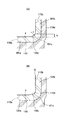
しかしながら、補強環101にフランジ部101bが形成された上述のような密封装置100は、図4(A)に示すように、補強環101の嵌合筒部101aとその外径側へ展開するフランジ部101bとの間の屈曲部101cにおける凹面側の曲率半径rが、成形時の加工誤差によって外輪110の内周面110aと端面110bとの間の面取り部110cの径方向高さhよりも大きくなってしまうことがあり、このような場合は、密封装置100を外輪110に取り付ける際に、補強環101の屈曲部101cの凹面が面取り部110cの角(端面110bの内径縁)110dとの干渉によって、補強環101の変形を生じ、あるいは図4(B)に示すように、面取り部110cの角110dとの干渉によって嵌合不足となって外輪110の端面110bと補強環101のフランジ部101bとの間に隙間Gを生じることがある。
However, in the
本発明は、以上のような点に鑑みてなされたものであって、その技術的課題は、補強環を有する密封装置において、嵌合相手側の面取り部との干渉による補強環の変形や嵌合不足を生じることなく精度良く取り付け可能とすることにある。 The present invention has been made in view of the above points, and its technical problem is that in a sealing device having a reinforcing ring, deformation or fitting of the reinforcing ring due to interference with the chamfered part on the mating counterpart side. The purpose is to enable accurate mounting without causing a lack of alignment.
本発明の密封装置は、互いに略同心的に配置されて相対移動可能な二部材のうち一方の部材に固定され、前記一方の部材の内周面に圧入嵌合される嵌合筒部と、この嵌合筒部の一端から外径方向へ展開して前記一方の部材の端面に当接されるフランジ部と、前記嵌合筒部と前記フランジ部との間の屈曲部とを有する補強環と、前記補強環に一体的に設けられ、先端部が他方の部材に摺動可能に密接されるシールリップと、を備え、前記屈曲部は、その屈曲内側の凹面を前記一方の部材の前記内周面と前記端面との間の面取り部に対面させ、前記凹面を前記端面から軸方向へ離間させる膨出した形状に形成されている。 The sealing device of the present invention is fixed to one member of substantially concentrically arranged with relatively movable two members to each other, and the fitting tube portion press-fitted to the inner peripheral surface of the front Symbol one member , reinforced with a bent portion between the one end of the fitting cylindrical portion and the flange portion to expand radially outward into contact with the end surface of the one member, and the fitting tube portion and the flange portion A ring, and a seal lip provided integrally with the reinforcing ring and having a tip slidably in contact with the other member, and the bent portion has a concave surface inside the bent portion of the one member. It is formed in a bulging shape that faces a chamfer between the inner peripheral surface and the end surface and separates the concave surface from the end surface in the axial direction .
上記構成の密封装置は、補強環が一方の部材に固定されると共に、シールリップの先端部が他方の部材に摺動可能に密接されることによってシール機能を奏するものであり、その取り付けに際しては、補強環の嵌合筒部を一方の部材の内周面に圧入嵌合すると共にこの補強環のフランジ部を一方の部材の端面と当接させる。このとき、補強環における嵌合筒部とフランジ部との間の屈曲部が、端面から軸方向へ離間しているため、この屈曲部が一方の部材の内周面と端面の間の面取り部と干渉することがない。 The sealing device having the above configuration has a sealing function when the reinforcing ring is fixed to one member and the tip of the seal lip is slidably in contact with the other member. The fitting tube portion of the reinforcing ring is press-fitted into the inner peripheral surface of one member, and the flange portion of the reinforcing ring is brought into contact with the end surface of the one member. At this time, since the bent portion between the fitting tube portion and the flange portion in the reinforcing ring is separated from the end surface in the axial direction, the bent portion is a chamfered portion between the inner peripheral surface and the end surface of one member. There is no interference with.
本発明に係る密封装置によれば、補強環を一方の部材に取り付ける際に、この補強環における嵌合筒部とフランジ部との間の屈曲部が、一方の部材の内周面と端面の間の面取り部と干渉しないので、補強環の変形や嵌合不足を生じることなく精度良く取り付けることができる。 According to the sealing device of the present invention, when the reinforcing ring is attached to one member, the bent portion between the fitting tube portion and the flange portion in the reinforcing ring is formed between the inner peripheral surface and the end surface of the one member. Since it does not interfere with the chamfered portion therebetween, it can be attached with high accuracy without causing deformation or insufficient fitting of the reinforcing ring.
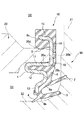
以下、本発明に係る密封装置を、自動車用車輪懸架装置に車輪を回転自在に支持する軸受ユニットの密封手段として適用した好ましい実施の形態について、図1及び図2を参照しながら説明する。 Hereinafter, a preferred embodiment in which a sealing device according to the present invention is applied as a sealing means of a bearing unit that rotatably supports a wheel on a vehicle wheel suspension will be described with reference to FIGS. 1 and 2.
まず図1において、参照符号20は外輪、参照符号30は、軸部32が外輪20に挿通され取付フランジ31に不図示の車輪が取り付けられるハブで、この外輪20とハブ30の軸部32の間に円周方向に並んだ不図示の球体が介在して軸受ユニットが構成されている。なお、外輪20は「一方の部材」に相当し、ハブ30は「他方の部材」に相当するものである。
In FIG. 1,
ハブ30の取付フランジ31と軸方向に対向する外輪20の端部には密封装置10が取り付けられている。この密封装置10は、外部S2から軸受内部空間S1へ泥水等が浸入するのを防止すると共に軸受内部空間S1内の不図示のグリースが外部S2へ漏洩するのを防止するものであって、外輪20に密封的に固定される金属製の補強環1と、ゴム状弾性材料(ゴム材料又はゴム状弾性を有する合成樹脂材料)からなる対ダスト用シールリップ2,3、対グリース用シールリップ4及び固定シール部5を備える。
The
すなわち密封装置10は、所定の金型(不図示)内に、予め所定の接着剤を塗布した補強環1を位置決めセットし、型閉じ状態において補強環1と金型内面との間に画成された環状のキャビティ内に、成形用ゴム又は成形用合成樹脂材料を充填して架橋硬化させることによって、対ダスト用シールリップ2,3、対グリース用シールリップ4及び固定シール部5の成形と同時に補強環1と一体化したものである。
That is, the
補強環1は、金属板を打ち抜きプレス成形したものであって、外輪20の端部内周面20aに圧入嵌合される嵌合筒部11と、その軸受内部空間S1側の一端から内周側へ折り返すように形成された筒状の折り返し部12と、さらにそこから内径側へ屈曲しながら延びる内向きフランジ部13と、嵌合筒部11における内向きフランジ部13と反対側の端部から外径側へ展開し外輪20の端面20bと当接される外向きフランジ部14と、この外向きフランジ部14の外径端部からハブ30の取付フランジ31と背反する方向へ屈曲形成された外径筒部15を備える。なお、外向きフランジ部14は「フランジ部」に相当するものである。
The reinforcing
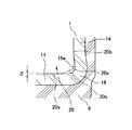
図2に一層明確に示すように、補強環1における嵌合筒部11は、外輪20の端部内周面20aに対して所定の締め代δが設定されており、補強環1における嵌合筒部11と外向きフランジ部14との間の屈曲部16は、その屈曲内側の凹面16aが外輪20の端面20bから軸方向へ離間する「逃げ」形状、すなわち外向きフランジ部14よりハブ30の取付フランジ31側へ膨出した形状に形成されている。また、外輪20の内周面20aと端面20bとの間には面取り部20cが形成されている。
As shown more clearly in FIG. 2, the
対ダスト用シールリップ2,3、対グリース用シールリップ4及び固定シール部5は互いに共通の基部6を有し、この基部6が、補強環1の外側面(ハブ30の取付フランジ31との対向面)を覆うように延びて、この補強環1に加硫接着によって一体接合されている。なお、対ダスト用シールリップ2,3、及び対グリース用シールリップ4は、「シールリップ」に相当するものである。
The
このうち、外径側の対ダスト用シールリップ2は、基部6のうち補強環1の内向きフランジ部13に接合された部分6aから、先端側が大径となるような円錐筒状をなして延び、外径側へ適当に曲げ変形を受けた状態で、先端が、軸心に対して略垂直な平面状をなすハブ30の取付フランジ31に摺動可能に密接されるものである。
Among these, the
また、内径側の対ダスト用シールリップ3は、基部6のうち補強環1の内向きフランジ部13の内径端に接合された部分6bから、先端側が大径となるような円錐筒状をなして延び、外径側へ適当に曲げ変形を受けた状態で、先端が、ハブ30の取付フランジ31と軸部32の間の湾曲面に摺動可能に密接されるものである。
Further, the dust lip seal lip 3 on the inner diameter side has a conical cylindrical shape in which the distal end side has a large diameter from a
対グリース用シールリップ4は、基部6のうち補強環1の内向きフランジ部13の内径端に接合された部分6bから、内径側の対ダスト用シールリップ3と反対側へ向いて延び、先端がハブ30の軸部32の外周面に僅かな締め代をもって摺動可能に密接している。
The seal lip 4 for grease extends from the
固定シール部5は、補強環1の外径筒部15を埋設した状態に形成された基部6の外径部6cの内周面に形成され、外輪20の端部外周面20dに適当に圧縮された状態で密接されるものである。
The
以上のような構成を備える密封装置10は、補強環1の嵌合筒部11の外周面が外輪20の内周面20aに圧入嵌合すると共に、この補強環1の外向きフランジ部14を外輪20の端面20bと当接させることによって、外輪20に軸方向位置決め状態で取り付けられた状態で、対ダスト用シールリップ2,3及び対グリース用シールリップ4がハブ30に摺動可能に密接され、固定シール部5が外輪20の端部外周面20dに密接されることによって、外部S2からの軸受内部空間S1への雨水、泥水あるいは塵埃等の異物が浸入するのを防止すると共に、軸受内部空間S1に充填された不図示のグリースが外部S2へ漏洩するのを防止するものである。
In the
そしてこの密封装置10の取り付けに際しては、補強環1の外向きフランジ部14が外輪20の端面20bと当接するまで、この補強環1の嵌合筒部11を外輪20の内周面20aに圧入していく。またこのとき、嵌合筒部11の圧入と同時に固定シール部5が外輪20の端部外周面20dに圧入外挿されていく。
When the sealing
ここで、補強環1における嵌合筒部11と外向きフランジ部14との間の屈曲部16は、外向きフランジ部14よりハブ30の取付フランジ31側へ膨出した形状に形成されているため、補強環1の外向きフランジ部14が外輪20の端面20bと当接しても、屈曲部16の屈曲内側の凹面16aが外輪20の面取り部20cにおける端面20b側の角部20eと干渉することがない。したがって、補強環1の変形や嵌合不足を生じることがなく、外輪20に精度良く位置決めして取り付けることができる。
Here, the
1 補強環
11 嵌合筒部
14 外向きフランジ部(フランジ部)
2,3 対ダスト用シールリップ(シールリップ)
4 対グリース用シールリップ(シールリップ)
5 固定シール部
20 外輪(一方の部材)
20a 内周面
20b 端面
20c 面取り部
30 ハブ(他方の部材)
DESCRIPTION OF
2,3 Seal lip for dust (seal lip)
4 Seal lip for grease (seal lip)
5
20a Inner
Claims (1)
前記補強環に一体的に設けられ、先端部が他方の部材に摺動可能に密接されるシールリップと、
を備え、前記屈曲部は、その屈曲内側の凹面を前記一方の部材の前記内周面と前記端面との間の面取り部に対面させ、前記凹面を前記端面から軸方向へ離間させる膨出した形状に形成されている、
ことを特徴とする密封装置。 Are arranged substantially concentrically fixed to one of the members of the relatively movable two members to each other, and the fitting tube portion press-fitted to the inner peripheral surface of the front Symbol one member, the fitting tube a flange portion that contacts the end surface of the one member to expand radially outward from one end, and a reinforcing ring which have a a bent portion between said fitting cylinder portion and the flange portion,
A seal lip provided integrally with the reinforcing ring and having a tip slidably in contact with the other member;
The bent portion bulges so that the concave surface inside the bent faces the chamfered portion between the inner peripheral surface and the end surface of the one member, and the concave surface is separated from the end surface in the axial direction . Formed into a shape ,
A sealing device characterized by that.
Priority Applications (1)
| Application Number | Priority Date | Filing Date | Title |
|---|---|---|---|
| JP2015078259A JP6600151B2 (en) | 2015-04-07 | 2015-04-07 | Sealing device |
Applications Claiming Priority (1)
| Application Number | Priority Date | Filing Date | Title |
|---|---|---|---|
| JP2015078259A JP6600151B2 (en) | 2015-04-07 | 2015-04-07 | Sealing device |
Publications (2)
| Publication Number | Publication Date |
|---|---|
| JP2016200157A JP2016200157A (en) | 2016-12-01 |
| JP6600151B2 true JP6600151B2 (en) | 2019-10-30 |
Family
ID=57422803
Family Applications (1)
| Application Number | Title | Priority Date | Filing Date |
|---|---|---|---|
| JP2015078259A Active JP6600151B2 (en) | 2015-04-07 | 2015-04-07 | Sealing device |
Country Status (1)
| Country | Link |
|---|---|
| JP (1) | JP6600151B2 (en) |
Family Cites Families (4)
| Publication number | Priority date | Publication date | Assignee | Title |
|---|---|---|---|---|
| JP2546477Y2 (en) * | 1992-02-06 | 1997-09-03 | エヌティエヌ株式会社 | Sealing device for constant velocity joints |
| JPH07183169A (en) * | 1993-12-22 | 1995-07-21 | Nippon Chemicon Corp | Chip-shaped solid electrolytic capacitor |
| JP2001351806A (en) * | 2000-06-07 | 2001-12-21 | Teikoku Tsushin Kogyo Co Ltd | Electronic parts |
| JP5836584B2 (en) * | 2010-11-02 | 2015-12-24 | Ntn株式会社 | Wheel bearing device |
-
2015
- 2015-04-07 JP JP2015078259A patent/JP6600151B2/en active Active
Also Published As
| Publication number | Publication date |
|---|---|
| JP2016200157A (en) | 2016-12-01 |
Similar Documents
| Publication | Publication Date | Title |
|---|---|---|
| JP5311649B2 (en) | Annular sealing device | |
| CN105745477A (en) | Method for manufacturing sealing device | |
| JP2017223257A (en) | Sealing structure | |
| US10473148B2 (en) | Socket assembly with an improved boot | |
| JP2014035035A (en) | Dust cover for ball joint | |
| CN112277529A (en) | Sealing device for hub assembly | |
| JP2018035855A (en) | Sealing device | |
| JPWO2009017022A1 (en) | Sealing device | |
| JP5935974B2 (en) | Center bearing support | |
| JP6793872B2 (en) | Sealed structure | |
| JP6600151B2 (en) | Sealing device | |
| JP2018071714A (en) | Seal ring and rolling bearing unit with seal ring | |
| JP6718734B2 (en) | Sealing device | |
| JP2006118625A (en) | Sealing device | |
| JP6765186B2 (en) | Sealing device | |
| JP6625340B2 (en) | Sealing device | |
| JP2005325924A (en) | Sealing device | |
| JP3204289U (en) | Sealing device | |
| JP7046514B2 (en) | Sealing device | |
| JP2017072153A (en) | Dust seal | |
| CN111226053A (en) | Sealing device | |
| JP6426828B2 (en) | Sealing device | |
| JP6803965B2 (en) | Seal ring | |
| JP6546034B2 (en) | Hub unit sealing device | |
| US20180045315A1 (en) | Sealing device |
Legal Events
| Date | Code | Title | Description |
|---|---|---|---|
| A621 | Written request for application examination |
Free format text: JAPANESE INTERMEDIATE CODE: A621 Effective date: 20180314 |
|
| A977 | Report on retrieval |
Free format text: JAPANESE INTERMEDIATE CODE: A971007 Effective date: 20190221 |
|
| A131 | Notification of reasons for refusal |
Free format text: JAPANESE INTERMEDIATE CODE: A131 Effective date: 20190306 |
|
| A521 | Request for written amendment filed |
Free format text: JAPANESE INTERMEDIATE CODE: A523 Effective date: 20190408 |
|
| TRDD | Decision of grant or rejection written | ||
| A01 | Written decision to grant a patent or to grant a registration (utility model) |
Free format text: JAPANESE INTERMEDIATE CODE: A01 Effective date: 20190904 |
|
| A61 | First payment of annual fees (during grant procedure) |
Free format text: JAPANESE INTERMEDIATE CODE: A61 Effective date: 20191004 |
|
| R150 | Certificate of patent or registration of utility model |
Ref document number: 6600151 Country of ref document: JP Free format text: JAPANESE INTERMEDIATE CODE: R150 |
|
| R250 | Receipt of annual fees |
Free format text: JAPANESE INTERMEDIATE CODE: R250 |