JP6598514B2 - Image recording apparatus, control method, and program - Google Patents
Image recording apparatus, control method, and program Download PDFInfo
- Publication number
- JP6598514B2 JP6598514B2 JP2015107878A JP2015107878A JP6598514B2 JP 6598514 B2 JP6598514 B2 JP 6598514B2 JP 2015107878 A JP2015107878 A JP 2015107878A JP 2015107878 A JP2015107878 A JP 2015107878A JP 6598514 B2 JP6598514 B2 JP 6598514B2
- Authority
- JP
- Japan
- Prior art keywords
- recording
- temperature
- value
- threshold
- image
- Prior art date
- Legal status (The legal status is an assumption and is not a legal conclusion. Google has not performed a legal analysis and makes no representation as to the accuracy of the status listed.)
- Active
Links
Images


Classifications
-
- B—PERFORMING OPERATIONS; TRANSPORTING
- B41—PRINTING; LINING MACHINES; TYPEWRITERS; STAMPS
- B41J—TYPEWRITERS; SELECTIVE PRINTING MECHANISMS, i.e. MECHANISMS PRINTING OTHERWISE THAN FROM A FORME; CORRECTION OF TYPOGRAPHICAL ERRORS
- B41J29/00—Details of, or accessories for, typewriters or selective printing mechanisms not otherwise provided for
- B41J29/38—Drives, motors, controls or automatic cut-off devices for the entire printing mechanism
-
- B—PERFORMING OPERATIONS; TRANSPORTING
- B41—PRINTING; LINING MACHINES; TYPEWRITERS; STAMPS
- B41J—TYPEWRITERS; SELECTIVE PRINTING MECHANISMS, i.e. MECHANISMS PRINTING OTHERWISE THAN FROM A FORME; CORRECTION OF TYPOGRAPHICAL ERRORS
- B41J2/00—Typewriters or selective printing mechanisms characterised by the printing or marking process for which they are designed
- B41J2/005—Typewriters or selective printing mechanisms characterised by the printing or marking process for which they are designed characterised by bringing liquid or particles selectively into contact with a printing material
- B41J2/01—Ink jet
- B41J2/015—Ink jet characterised by the jet generation process
- B41J2/04—Ink jet characterised by the jet generation process generating single droplets or particles on demand
- B41J2/045—Ink jet characterised by the jet generation process generating single droplets or particles on demand by pressure, e.g. electromechanical transducers
- B41J2/04501—Control methods or devices therefor, e.g. driver circuits, control circuits
- B41J2/04528—Control methods or devices therefor, e.g. driver circuits, control circuits aiming at warming up the head
-
- B—PERFORMING OPERATIONS; TRANSPORTING
- B41—PRINTING; LINING MACHINES; TYPEWRITERS; STAMPS
- B41J—TYPEWRITERS; SELECTIVE PRINTING MECHANISMS, i.e. MECHANISMS PRINTING OTHERWISE THAN FROM A FORME; CORRECTION OF TYPOGRAPHICAL ERRORS
- B41J2/00—Typewriters or selective printing mechanisms characterised by the printing or marking process for which they are designed
- B41J2/005—Typewriters or selective printing mechanisms characterised by the printing or marking process for which they are designed characterised by bringing liquid or particles selectively into contact with a printing material
- B41J2/01—Ink jet
- B41J2/015—Ink jet characterised by the jet generation process
- B41J2/04—Ink jet characterised by the jet generation process generating single droplets or particles on demand
- B41J2/045—Ink jet characterised by the jet generation process generating single droplets or particles on demand by pressure, e.g. electromechanical transducers
- B41J2/04501—Control methods or devices therefor, e.g. driver circuits, control circuits
- B41J2/0454—Control methods or devices therefor, e.g. driver circuits, control circuits involving calculation of temperature
-
- B—PERFORMING OPERATIONS; TRANSPORTING
- B41—PRINTING; LINING MACHINES; TYPEWRITERS; STAMPS
- B41J—TYPEWRITERS; SELECTIVE PRINTING MECHANISMS, i.e. MECHANISMS PRINTING OTHERWISE THAN FROM A FORME; CORRECTION OF TYPOGRAPHICAL ERRORS
- B41J2/00—Typewriters or selective printing mechanisms characterised by the printing or marking process for which they are designed
- B41J2/005—Typewriters or selective printing mechanisms characterised by the printing or marking process for which they are designed characterised by bringing liquid or particles selectively into contact with a printing material
- B41J2/01—Ink jet
- B41J2/015—Ink jet characterised by the jet generation process
- B41J2/04—Ink jet characterised by the jet generation process generating single droplets or particles on demand
- B41J2/045—Ink jet characterised by the jet generation process generating single droplets or particles on demand by pressure, e.g. electromechanical transducers
- B41J2/04501—Control methods or devices therefor, e.g. driver circuits, control circuits
- B41J2/04551—Control methods or devices therefor, e.g. driver circuits, control circuits using several operating modes
-
- B—PERFORMING OPERATIONS; TRANSPORTING
- B41—PRINTING; LINING MACHINES; TYPEWRITERS; STAMPS
- B41J—TYPEWRITERS; SELECTIVE PRINTING MECHANISMS, i.e. MECHANISMS PRINTING OTHERWISE THAN FROM A FORME; CORRECTION OF TYPOGRAPHICAL ERRORS
- B41J2/00—Typewriters or selective printing mechanisms characterised by the printing or marking process for which they are designed
- B41J2/005—Typewriters or selective printing mechanisms characterised by the printing or marking process for which they are designed characterised by bringing liquid or particles selectively into contact with a printing material
- B41J2/01—Ink jet
- B41J2/015—Ink jet characterised by the jet generation process
- B41J2/04—Ink jet characterised by the jet generation process generating single droplets or particles on demand
- B41J2/045—Ink jet characterised by the jet generation process generating single droplets or particles on demand by pressure, e.g. electromechanical transducers
- B41J2/04501—Control methods or devices therefor, e.g. driver circuits, control circuits
- B41J2/04553—Control methods or devices therefor, e.g. driver circuits, control circuits detecting ambient temperature
-
- B—PERFORMING OPERATIONS; TRANSPORTING
- B41—PRINTING; LINING MACHINES; TYPEWRITERS; STAMPS
- B41J—TYPEWRITERS; SELECTIVE PRINTING MECHANISMS, i.e. MECHANISMS PRINTING OTHERWISE THAN FROM A FORME; CORRECTION OF TYPOGRAPHICAL ERRORS
- B41J2/00—Typewriters or selective printing mechanisms characterised by the printing or marking process for which they are designed
- B41J2/005—Typewriters or selective printing mechanisms characterised by the printing or marking process for which they are designed characterised by bringing liquid or particles selectively into contact with a printing material
- B41J2/01—Ink jet
- B41J2/015—Ink jet characterised by the jet generation process
- B41J2/04—Ink jet characterised by the jet generation process generating single droplets or particles on demand
- B41J2/045—Ink jet characterised by the jet generation process generating single droplets or particles on demand by pressure, e.g. electromechanical transducers
- B41J2/04501—Control methods or devices therefor, e.g. driver circuits, control circuits
- B41J2/04563—Control methods or devices therefor, e.g. driver circuits, control circuits detecting head temperature; Ink temperature
-
- B—PERFORMING OPERATIONS; TRANSPORTING
- B41—PRINTING; LINING MACHINES; TYPEWRITERS; STAMPS
- B41J—TYPEWRITERS; SELECTIVE PRINTING MECHANISMS, i.e. MECHANISMS PRINTING OTHERWISE THAN FROM A FORME; CORRECTION OF TYPOGRAPHICAL ERRORS
- B41J2/00—Typewriters or selective printing mechanisms characterised by the printing or marking process for which they are designed
- B41J2/005—Typewriters or selective printing mechanisms characterised by the printing or marking process for which they are designed characterised by bringing liquid or particles selectively into contact with a printing material
- B41J2/01—Ink jet
- B41J2/015—Ink jet characterised by the jet generation process
- B41J2/04—Ink jet characterised by the jet generation process generating single droplets or particles on demand
- B41J2/045—Ink jet characterised by the jet generation process generating single droplets or particles on demand by pressure, e.g. electromechanical transducers
- B41J2/04501—Control methods or devices therefor, e.g. driver circuits, control circuits
- B41J2/0458—Control methods or devices therefor, e.g. driver circuits, control circuits controlling heads based on heating elements forming bubbles
-
- B—PERFORMING OPERATIONS; TRANSPORTING
- B41—PRINTING; LINING MACHINES; TYPEWRITERS; STAMPS
- B41J—TYPEWRITERS; SELECTIVE PRINTING MECHANISMS, i.e. MECHANISMS PRINTING OTHERWISE THAN FROM A FORME; CORRECTION OF TYPOGRAPHICAL ERRORS
- B41J2/00—Typewriters or selective printing mechanisms characterised by the printing or marking process for which they are designed
- B41J2/005—Typewriters or selective printing mechanisms characterised by the printing or marking process for which they are designed characterised by bringing liquid or particles selectively into contact with a printing material
- B41J2/01—Ink jet
- B41J2/135—Nozzles
- B41J2/14—Structure thereof only for on-demand ink jet heads
- B41J2/14016—Structure of bubble jet print heads
- B41J2/14153—Structures including a sensor
-
- B—PERFORMING OPERATIONS; TRANSPORTING
- B41—PRINTING; LINING MACHINES; TYPEWRITERS; STAMPS
- B41J—TYPEWRITERS; SELECTIVE PRINTING MECHANISMS, i.e. MECHANISMS PRINTING OTHERWISE THAN FROM A FORME; CORRECTION OF TYPOGRAPHICAL ERRORS
- B41J2/00—Typewriters or selective printing mechanisms characterised by the printing or marking process for which they are designed
- B41J2/005—Typewriters or selective printing mechanisms characterised by the printing or marking process for which they are designed characterised by bringing liquid or particles selectively into contact with a printing material
- B41J2/01—Ink jet
- B41J2/17—Ink jet characterised by ink handling
- B41J2/175—Ink supply systems ; Circuit parts therefor
- B41J2/17503—Ink cartridges
- B41J2/17553—Outer structure
-
- B—PERFORMING OPERATIONS; TRANSPORTING
- B41—PRINTING; LINING MACHINES; TYPEWRITERS; STAMPS
- B41J—TYPEWRITERS; SELECTIVE PRINTING MECHANISMS, i.e. MECHANISMS PRINTING OTHERWISE THAN FROM A FORME; CORRECTION OF TYPOGRAPHICAL ERRORS
- B41J29/00—Details of, or accessories for, typewriters or selective printing mechanisms not otherwise provided for
- B41J29/377—Cooling or ventilating arrangements
Landscapes
- Ink Jet (AREA)
- Particle Formation And Scattering Control In Inkjet Printers (AREA)
Description
本発明は、画像記録装置、制御方法およびプログラムに関する。 The present invention relates to an image recording apparatus, a control method, and a program.
インクを吐出するための複数の吐出口を配列した吐出口列を有する記録ヘッドを記録媒体に対して走査させながらインクを吐出することにより、記録媒体上に画像を記録する画像記録装置が従来より知られている。 2. Description of the Related Art Conventionally, an image recording apparatus that records an image on a recording medium by ejecting ink while scanning a recording medium with a recording head having an ejection port array in which a plurality of ejection ports for ejecting ink are arranged is used. Are known.
このような画像記録装置において、電気熱変換素子を用い、電気熱変換素子にパルスを与えることで発生する熱エネルギーを利用して吐出口からインクを吐出する記録方式が知られている。このような記録方式においては、吐出口列内の複数の吐出口に均一に熱エネルギーを加えたとしても、吐出口が配列された位置に応じたインクの温度分布が生じてしまう場合がある。インクの温度が高いほどインクの吐出量は多くなるため、この温度分布に応じて吐出口間において吐出量に変動が生じ、これにより記録される画像において濃度むらが発生してしまう虞がある。 In such an image recording apparatus, a recording system is known in which an electrothermal conversion element is used and ink is ejected from an ejection port using thermal energy generated by applying a pulse to the electrothermal conversion element. In such a recording method, even if thermal energy is uniformly applied to a plurality of ejection ports in the ejection port array, an ink temperature distribution may occur depending on the position where the ejection ports are arranged. The higher the ink temperature, the greater the ink ejection amount. Therefore, the ejection amount varies between the ejection ports in accordance with this temperature distribution, which may cause uneven density in the recorded image.
特許文献1には、上述の濃度むらを抑制するため、吐出口の配列方向において互いに異なる位置に設けられた複数の温度センサーと、吐出口の近傍を加熱することにより温調を行う温調ヒータ(以下、サブヒータとも称する)とを有する記録ヘッドを用いることが開示されている。より詳細には、吐出口列の配列方向における一方の端部近傍と他方の端部近傍に互いに独立して駆動可能な2つのサブヒータを有する記録ヘッドが記載されている。同文献によれば、記録に使用する吐出口の数を少なくして記録を行う記録モードにおいて吐出口列内の一方の端部近傍と他方の端部近傍でインクの温度差が生じた場合であっても、このような記録ヘッドを用いてその温度差に応じたパワーをそれぞれのサブヒータに設定して独立に駆動することにより、両端部での温度差を解消できると記載されている。
In
しかしながら、近年の記録ヘッドでは、例えば吐出口列内の複数の吐出口をすべて使うような記録モードにおいても、吐出口列内の中央側の温度が端部側の温度よりも高くなるような温度分布が生じる虞があることがわかった。このような温度分布が生じた場合、記録媒体上において吐出口列の中央側から記録された領域と端部側から記録された領域の間で濃度むらが発生する虞がある。 However, in recent recording heads, for example, even in a recording mode in which all of the plurality of ejection ports in the ejection port array are used, the temperature at which the central side temperature in the ejection port array becomes higher than the end side temperature. It was found that there is a risk of distribution. When such a temperature distribution occurs, there is a possibility that density unevenness may occur between the area recorded from the center side of the ejection port array and the area recorded from the end side on the recording medium.
この温度分布は、吐出口列の端部の方が基板を介した放熱が起こり易く温度が低下し易いこと等に由来すると考えられる。また、近年では吐出口列の端部からの吐出におけるインクの着弾位置ずれを抑制するため、吐出口列の端部側からの吐出量を中央側からの吐出量よりも少なくして記録することが知られている。この場合、吐出口列内の中央側に位置する吐出口に対応する電気熱変換素子の駆動回数が多くなるため、上述の温度分布がより顕著に発生する虞がある。 This temperature distribution is considered to be derived from the fact that the end of the discharge port array is more likely to dissipate heat through the substrate and the temperature tends to decrease. Also, in recent years, in order to suppress displacement of the landing position of ink during ejection from the end of the ejection port array, recording is performed with the ejection amount from the end side of the ejection port array being smaller than the ejection amount from the center side. It has been known. In this case, since the number of times of driving the electrothermal conversion element corresponding to the ejection port located on the center side in the ejection port array increases, the above-described temperature distribution may occur more significantly.
特許文献1に記載された技術では、サブヒータは吐出口列の両端部にのみ設けられているため、上述のような吐出口列の中央部の温度が両端部の温度よりも高くなるような場合には温度分布を解消することができない。また、特許文献1のように複数のサブヒータを独立に駆動可能な記録ヘッドでは電気回路の構成等が煩雑となるため、記録ヘッドの大型化やコストアップが生じる虞がある。
In the technique described in
また、特許文献1に記載されているように、記録に用いる吐出口近傍の温度センサーおよび記録に用いない吐出口近傍の温度センサーのそれぞれから検出した温度から温度差を算出して、温度分布をなくすようにサブヒータの駆動制御する場合であっても、以下のような課題が生じる虞があることがわかった。記録に用いる吐出口の使用頻度が高い場合には、近傍の温度センサー温度が昇温していくため、記録に用いない吐出口近傍の温度センサーとの温度差が拡大し、記録に用いない吐出口近傍のサブヒータのパワーをさらに強める必要がある。その結果、検出温度差および温度分布は解消していくものの、記録ヘッド全体が蓄熱して温度が上昇してしまうため、過昇温状態になり、吐出性能を低下させてしまう虞があることがわかった。
Further, as described in
本発明は上記の課題を鑑みて為されたものであり、吐出口列の中央側の温度が端部側の温度よりも高くなるような温度分布に由来する濃度むらを抑制した記録を行うことを目的とするものである。 The present invention has been made in view of the above problems, and performs recording while suppressing density unevenness derived from a temperature distribution such that the temperature on the center side of the discharge port array is higher than the temperature on the end side. It is intended.
そこで、本発明は、基板と、所定の色のインクを吐出するための熱エネルギーを生成する複数の記録素子が前記基板上に所定方向に配列された記録素子列と、前記記録素子列内の前記所定方向における第1の位置の記録素子近傍の温度を検知するための第1の検知素子と、前記所定方向において前記第1の位置よりも前記記録素子列の中央部に近い第2の位置の記録素子近傍の温度を検知するための第2の検知素子と、少なくとも前記第1の位置の記録素子近傍のインクを加熱するための加熱素子と、を有する記録ヘッドを用いて記録媒体上に画像を記録するための画像記録装置であって、画像を記録する際の記録条件に関する情報を取得する取得手段と、前記取得手段によって取得された前記情報に基づいて第1の閾値を決定する決定手段と、前記第1の検知素子により検知された温度と、前記第2の検知素子により検知された温度と、の差が前記第1の閾値よりも大きい場合に前記加熱素子による加熱を実行するように、前記加熱素子を制御する制御手段と、を有することを特徴とする。 Accordingly, the present invention includes a substrate and a recording element array in which a plurality of recording elements arranged in a predetermined direction on said substrate for generating thermal energy for discharging Jo Tokoro color ink, the recording elements in a column predetermined a first sensing element for sensing the temperature of the record elements near the first position in the direction, the predetermined direction in the than the first position recording element array second near the center portion of the using a second sensing element for sensing the temperature of the record elements near the position of a heating element for heating the ink in the record element at least near the first position, the recording head having An image recording apparatus for recording an image on a recording medium, the acquisition unit acquiring information related to a recording condition when recording an image, and a first threshold value based on the information acquired by the acquisition unit Determination means to determine , A temperature sensed by said first sensing element, so that the difference, the temperature sensed by the second sensing element performs the heating by the heating element is greater than the first threshold value And a control means for controlling the heating element.
本発明に係る画像記録装置、画像記録方法およびプログラムによれば、吐出口列の中央側の温度が端部側の温度よりも高くなるような温度分布に由来する濃度むらを抑制した記録を行うことが可能となる。 According to the image recording apparatus, the image recording method, and the program according to the present invention, the recording is performed while suppressing the density unevenness derived from the temperature distribution such that the temperature on the center side of the ejection port array is higher than the temperature on the end side. It becomes possible.
以下に図面を参照し、本発明の第1の実施形態について詳細に説明する。 Hereinafter, a first embodiment of the present invention will be described in detail with reference to the drawings.
(第1の実施形態)
(1)画像記録装置の機械的構成
(1−1)装置の概略
図1は本発明の一実施形態に係る画像記録装置(以下、プリンタともいう)の外観を示している。これはいわゆるシリアル走査型のプリンタであり、記録媒体Pの搬送方向(Y方向)に対して直交する走査方向(X方向)に記録ヘッドを走査して画像を記録するものである。
(First embodiment)
(1) Mechanical Configuration of Image Recording Apparatus (1-1) Outline of Apparatus FIG. 1 shows the appearance of an image recording apparatus (hereinafter also referred to as a printer) according to an embodiment of the present invention. This is a so-called serial scanning type printer, which records an image by scanning a recording head in a scanning direction (X direction) orthogonal to the conveyance direction (Y direction) of the recording medium P.
図1を用いてこの画像記録装置の構成および記録時の動作の概略を説明する。まず不図示の給紙モータによりギヤを介して駆動される給紙ローラによって記録媒体Pを保持しているスプール6より記録媒体PがY方向に搬送される。一方、所定の搬送位置において不図示のキャリッジモータによりキャリッジユニット2をX方向に延在するガイドシャフト8に沿って走査させる。そして、この走査の過程で、エンコーダ7によって得られる位置信号に基づいたタイミングでキャリッジユニット2に着脱自在に装着される記録ヘッド(後述)の吐出口から吐出動作を行わせ、ノズル配列範囲に対応した一定のバンド幅を記録する。本実施形態においては、走査速度40インチ毎秒で走査し、600dpiのタイミングで吐出動作を行う構成とした。その後、記録媒体の搬送を行い、さらに次のバンド幅について記録を行う構成となっている。
The configuration of this image recording apparatus and the outline of the operation during recording will be described with reference to FIG. First, the recording medium P is conveyed in the Y direction from the
このようなプリンタでは、1回の走査で記録媒体上の単位領域に画像を記録(いわゆる1パス記録)しても良いし、複数回の走査で画像を記録(いわゆるマルチパス記録)しても良い。1パス記録を行う場合には各走査間でバンド幅分の記録媒体の搬送を行っても良い。また、マルチパス記録を行う場合には、1走査毎には搬送を行わず、記録媒体上の単位領域に対して複数回走査を行ってから、該単位領域に1バンド前後の搬送を行っても良い。また、他のマルチパス記録として、1走査毎に所定のマスクパターンによって間引かれたデータを記録してから1/nバンド前後の紙送りを行い、再度走査を行うことによって、記録媒体上の単位領域に対し記録に関与するノズルを異ならせた複数回(n回)の走査と搬送とによって画像を完成させる方法がある。 In such a printer, an image may be recorded in a unit area on the recording medium by one scan (so-called one-pass recording), or an image may be recorded by a plurality of scans (so-called multi-pass recording). good. When one-pass printing is performed, the recording medium corresponding to the bandwidth may be transported between each scan. In addition, when performing multi-pass printing, transport is not performed for each scan, and a unit area on the recording medium is scanned a plurality of times, and then transporting around one band is performed on the unit area. Also good. As another multi-pass printing, data thinned out by a predetermined mask pattern is recorded every scan, and then paper is fed around 1 / n band, and scanning is performed again. There is a method in which an image is completed by a plurality of times (n times) of scanning and conveyance in which nozzles involved in recording are made different for a unit area.
記録ヘッド9に対しては、吐出駆動のための信号パルスやヘッド温調用信号などを供給するためのフレキシブル配線基板(不図示)が取り付けられている。フレキシブル基板の他端は、本プリンタの制御を実行する制御回路を備えた制御回路(後述)に接続されている。
A flexible wiring substrate (not shown) for supplying a signal pulse for ejection driving, a head temperature adjustment signal, and the like is attached to the
なお、キャリッジモータからキャリッジユニット2への駆動力の伝達には、キャリッジベルトを用いることができる。しかしキャリッジベルトの代わりに、例えばキャリッジモータにより回転駆動され、主走査方向に延在するリードスクリュと、キャリッジユニット2に設けられ、リードスクリュの溝に係合する係合部とを具えたものなど、他の駆動方式を用いることも可能である。 A carriage belt can be used to transmit the driving force from the carriage motor to the carriage unit 2. However, instead of the carriage belt, for example, a lead screw that is rotationally driven by a carriage motor and extends in the main scanning direction, and an engagement portion that is provided in the carriage unit 2 and engages with a groove of the lead screw, etc. Other driving methods can also be used.
送給された記録媒体Pは、給紙ローラとピンチローラとに挟持搬送されて、プラテン4上の記録位置(記録ヘッド9の主走査領域)に導かれる。通常休止状態では記録ヘッド9のフェイス面にはキャッピングが施されているため、記録に先立ってキャップを開放して記録ヘッド9ないしキャリッジユニット2を走査可能状態にする。その後、1走査分のデータがバッファに蓄積されたらキャッリッジモータ3によりキャリッジユニット2を走査させ、上述のように記録を行う。
The fed recording medium P is nipped and conveyed between a paper feed roller and a pinch roller and guided to a recording position on the platen 4 (main scanning area of the recording head 9). Since the face surface of the
(1−2)記録ヘッドの構成
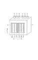
図2は、上記プリンタのキャリッジユニット2に搭載される記録ヘッド9を、インクが吐出される方向から示した模式的斜視図である。ここで、記録ヘッド9には、X方向に異なる色調(色、濃度を含む)のインク、例えば、ブラック(Bk)、ライトシアン(Lc)、シアン(C)、ライトマゼンタ(Lm)、マゼンタ(M)およびイエロー(Y)のインクを吐出可能な複数の吐出口列11〜16が2つの基板上10に並置されている。各吐出口列に対しては、インク導入部23から記録ヘッド9内部のインク流路を介してインクが供給される。インク導入部23にはインクタンクより供給チューブ45を介してインクが導入される。
(1-2) Configuration of Recording Head FIG. 2 is a schematic perspective view showing the
図3に例えば半導体から形成された支持基板10の詳細な構成を説明する透視図を示す。なお、図3(a)は支持基盤10をXY平面に対して垂直な方向から見た場合における透視図である。また、図3(b)は支持基板10をY方向下流側から見た場合における図3(a)に示す直線ABの位置の透視図である。
FIG. 3 is a perspective view illustrating a detailed configuration of the
図3は記録ヘッド9に並置されている2つの支持基板のうち、吐出口列11〜13に対応したものである。なお、簡単のため、図3には実際の縮尺とは異なるものを図示している。本実施形態における吐出口列11〜13は、それぞれ2つの列から形成されている。これらの2列の列が、それぞれ向かい合う列に対して1200dpi(ドット/インチ)ずらされた状態で、Y方向(所定方向)に640個ずつ、計1280個の吐出口55および吐出口に対向した電気熱変換素子(記録素子、メインヒータとも称する)56がY方向(所定方向)に配列されることにより、吐出口列11〜13および電気熱変換素子列(記録素子列)が形成されている。なお、本実施形態においては1200dpiは約0.02mmに相当する。この電気熱変換素子にパルスを加えることにより、吐出口からインクを吐出するための熱エネルギーを生成することができる。なお、ここでは電気熱変換素子を用いる場合について記載したが、圧電素子などを用いることも可能である。また、支持基板10上であって、吐出口列のY方向の端部には、支持基板10の端部の温度を検出するためのダイオードからなる温度センサー(検知素子)53が形成されている。温度センサー53はX方向について2つの吐出口列(例えば吐出口11および12)の中間、Y方向について端部の吐出口から0.2mm離れた位置に形成され、1つの温度センサー53で2つの吐出口列の端部温度を検出する構成となっている。吐出口列のY方向の中央部には、吐出口列の中央部の温度を検出するためのダイオードからなる温度センサー(検知素子)54が形成されており、1つの温度センサー54で2つの吐出口列の中央部温度を検出する構成となっている。吐出口内にあるインクの温度を調整するためのサブヒータ(加熱素子)17は、3つの吐出口列11〜13を取り囲むようにして一続きの部材にて形成されており、X方向についてノズル列15から1.2mm外側、Y方向について温度センサー20から0.2mm外側に位置する。なお、図3(b)に模式的に示すように、サブヒータ17、中央部温度センサー54は支持基板10上に設けられた吐出口部材57の内部に支持基板10と接合するように形成されている。また、電気熱変換素子56はインク流路内に支持基板10と接合するように形成されている。
FIG. 3 corresponds to the
(2)制御系の構成例
図4は本実施形態において用いた画像記録装置の制御回路の構成例を示す。図4において、101はプログラマブル・ペリフェラル・インターフェイス(以下PPIとする)であり、ホストコンピュータ100から送られてくる指令信号(コマンド)や記録データを含む記録情報信号を受信してMPU102に転送するとともに、ホストコンピュータ100に対しては必要に応じプリンタのステータス情報を送出する。また、ユーザーがプリンタに対して各種設定を行う設定入力部やユーザーに対してメッセージを表示する表示部などを有したコンソール106との間で入出力を行うとともに、キャリッジユニット2ないし記録ヘッド9がホームポジションにあることを検出するホームポジションセンサーや、キャッピングセンサーなどを含むセンサー群107よりの信号入力を受容する。
(2) Configuration Example of Control System FIG. 4 shows a configuration example of the control circuit of the image recording apparatus used in this embodiment. In FIG. 4,
MPU(マイクロプロセッシングユニット)102は、制御用ROM105に記憶された制御プログラムに従って、プリンタ内の各部を制御する。103は受信した信号を格納し、あるいはMPU102のワークエリアとして使用され、また各種データを一時的に記憶するためのRAMである。104はフォント発生用ROMで、コード情報に対応して文字や記録等のパターン情報を記憶しており、入力したコード情報に対応して各種パターン情報を出力する。121はRAM103等に展開された記録データを記憶するためのプリントバッファであって、複数行記録分の容量を持つ。制御用ROM105には上記制御プログラムのほか、後述する制御の過程で使用されるプログラムデータ(例えば本実施形態の主要部に係るサブヒータ制御の開始タイミングをMPUが決定するためのデータ)等に対応した固定データを格納しておくことができる。これらの各部は、アドレスバス117およびデータバス118を介して、MPU102により制御される。また、MPU102は、記録ヘッド9内に配置された端部温度センサー53および中央部温度センサー54から検知される温度を取得し、これらの温度に基づいて上述のプログラムデータを生成する。
An MPU (microprocessing unit) 102 controls each unit in the printer according to a control program stored in the
114、115および116は、それぞれ、キャッピングモータ113、キャリッジモータ3および給紙モータ5をMPU102の制御に応じて駆動するためのモータドライバである。
109はシートセンサーであり、記録媒体の有無、すなわち記録媒体が記録ヘッド9による記録が可能な位置に供給されたか否かを検知する。111は上述のプログラムデータに応じて記録ヘッド9の発熱部(メインヒータ、サブヒータ)を駆動するためのドライバを示している。122はプリンタ本体の設置環境における環境温度および環境湿度を検出するための温湿度センサーである。124は上記各部へ電源を供給する電源部であり、駆動電源装置としてACアダプタと電池とを有している。
上記プリンタおよびこれに対して記録情報信号を供給するホストコンピュータ100からなる記録システムにおいては、ホストコンピュータ100よりパラレルポート、赤外線ポート、あるいはネットワーク等を介して記録データ送信する際、その先頭部分に所要のコマンドが付加される。そのコマンドとしては、例えば記録の行われる記録媒体の種類(普通紙、OHPシート、光沢紙等の種類や、さらには転写フィルム、厚紙、バナー紙等の特殊な記録媒体の種別)、媒体サイズ(A0判、A1判、A2判、B0判、B1判、B2判など)、記録品位(ドラフト、高品位、中品位、特定色の強調、モノクローム/カラーの種別など)、給紙経路(プリンタが備える記録媒体の送給手段の形態や種類に応じて定められる。例えばASF、手差し、給紙カセット1、給紙カセット2など)、およびオブジェクトの自動判別の有無などがある。また、記録媒体でのインクの定着性を向上するための処理液を付与する構成が採用される場合には、その付与の有無を定める情報等がコマンドとして送信されることもある。
In the recording system including the printer and the
これらのコマンドに従って、プリンタ側では前述したROM105から記録に必要なデータを読み込み、それらのデータに基づいて記録を行う。データとしては、例えば上述したマルチパス記録を行う際の記録パス数や、記録媒体単位面積あたりのインクの打ち込み量および記録方向等を決定するためのものがある。またその他、マルチパス記録を行う際に適用されるデータ間引き用のマスク種類や、記録ヘッド9の駆動条件(たとえば発熱部に印加する駆動パルスの形状、印加時間等)、ドットのサイズ、記録媒体搬送の条件、使用する色数、さらにはキャリッジ速度等もある。
In accordance with these commands, the printer reads data necessary for recording from the
以下に本実施形態におけるサブヒータの駆動制御の一例を詳細に説明する。 Hereinafter, an example of the drive control of the sub heater in the present embodiment will be described in detail.
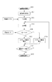
図5は本実施形態におけるサブヒータの閾値を単位領域に対する走査の回数に応じて変更する制御のフローを説明するフローチャートである。 FIG. 5 is a flowchart for explaining a control flow for changing the threshold value of the sub-heater according to the number of scans for the unit area in the present embodiment.
画像が記録開始される(ステップS101)と、まず、記録媒体に対する記録ヘッドの主走査が開始される(ステップS102)。そして、端部温度センサー53からの温度検出値と、中央部温度センサー54からの検出温度の差(温度差)ΔT(℃)を算出し、予め定められた閾値Tth(℃)と比較を始める(ステップS103)。本実施形態では閾値Tth(℃)は3℃であるとする。この閾値Tth(℃)は適宜異なる値とすることができ、シミュレーション等により温度差を解消するために適する値を算出し、その値に関する情報予め記録装置内のROM105に記憶させておくことができる。
When recording of an image is started (step S101), first, main scanning of the recording head with respect to the recording medium is started (step S102). Then, a difference (temperature difference) ΔT (° C.) between the temperature detection value from the
温度差ΔT(℃)が閾値Tthよりも大きいと判断された場合、端部側と中央側の温度差を縮小するため、サブヒータの駆動が開始される(ステップS104)。一方、温度差ΔT(℃)が閾値Tth以下であると判断された場合、サブヒータは駆動されない(ステップS105)。その時点でサブヒータの駆動が実行されていた場合には、サブヒータの駆動が停止される。 When it is determined that the temperature difference ΔT (° C.) is larger than the threshold value Tth, the sub heater is driven to reduce the temperature difference between the end and the center (step S104). On the other hand, when it is determined that the temperature difference ΔT (° C.) is equal to or less than the threshold value Tth, the sub heater is not driven (step S105). If driving of the sub-heater has been executed at that time, the driving of the sub-heater is stopped.
その後は画像記録が終了したか否かを判定し(ステップS106)、全てのデータの記録が終了していれば画像記録動作を終了する(ステップS107)。終了していない場合、ステップ102へと戻り、データが終了するまで同様の処理を続行する。 Thereafter, it is determined whether or not the image recording has been completed (step S106). If all the data has been recorded, the image recording operation is terminated (step S107). If not finished, the process returns to step 102 and the same processing is continued until the data is finished.
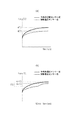
図6は図5で説明したフローに基づく制御有無による、端部温度センサー値と中央部温度センサー値の記録中温度推移を示す図である。 FIG. 6 is a diagram showing the temperature transition during recording of the end part temperature sensor value and the center part temperature sensor value depending on the presence or absence of control based on the flow described in FIG.
図6(a)は本実施形態を適用せずにA0サイズ ライトシアン100%デューティの画像を記録する場合の吐出口列12の温度推移である。ここでは、記録開始前にサブヒータとインクを吐出するために用いる電気熱変換素子を用いた温調制御によって記録開始前にヘッド温度を35℃に上昇させたのち、記録を開始している。吐出口列12は100%デューティ記録を行うため、各吐出口はほぼ均一の頻度でインクを吐出するが、Y方向端部側の領域は支持基板10を介して外気へ放熱しやすく、中央部と比較して温度が上昇しにくい傾向がある。したがって、記録の終了する108秒後には、端部温度センサー値が約42℃、中央部温度センサー値が約50℃となった。
FIG. 6A shows the temperature transition of the
一方、図6(b)は本実施形態を適用して同様の記録を実施した場合の吐出口列12の温度推移である。記録が開始してから34秒後に端部温度センサー値と中央部温度センサー値との温度差が3℃を超えたため、サブヒータ17による加熱が開始される。サブヒータは放熱しやすいY方向端部側を中心的に加熱するため、端部温度センサー値の上昇速度が早まる。そのため中央部温度センサー値と端部温度センサー値との温度差は縮小し、記録終了時点では温度差が約1℃となっている。ただし、サブヒータの加熱により記録ヘッド全体の温度もやや上昇したため、端部温度センサー値は約51℃、中央部温度センサー値は約52℃で記録を終了した。
On the other hand, FIG. 6B shows the temperature transition of the
図7は記録終了時点の吐出口列12の温度分布を示す図である。なお、図7(a)は本実施形態を適用しない場合における温度分布を、また、図7(b)は本実施形態を適用した場合における温度分布をそれぞれ示している。
FIG. 7 is a diagram showing the temperature distribution of the
本実施形態を適用しない場合には、図7(a)に示すように吐出口列中央部の温度が高く、端部が低い温度分布である。これに対し、本実施形態を適用することにより、図7(b)に示すように吐出口列内の温度分布はほぼ均一となる。 When this embodiment is not applied, as shown in FIG. 7A, the temperature distribution is high in the central portion of the discharge port array and low in the end portion. On the other hand, by applying this embodiment, the temperature distribution in the discharge port array becomes substantially uniform as shown in FIG. 7B.
このように、本実施形態によれば、温度差が閾値より高い場合にサブヒータを駆動し、温度差が閾値以下となった場合にサブヒータの駆動を停止することで、吐出口列内(記録素子列内)の温度分布をほぼ均一にし、温度分布に由来する濃度むらを好適に抑制することが可能となる。 As described above, according to the present embodiment, the sub heater is driven when the temperature difference is higher than the threshold, and the sub heater is stopped when the temperature difference is equal to or less than the threshold. The temperature distribution in the column) can be made substantially uniform, and uneven density due to the temperature distribution can be suitably suppressed.
(第2の実施形態)
本実施形態では、記録媒体上の単位領域に対する記録ヘッドの走査の回数に応じて異なる閾値を設定する。
(Second Embodiment)
In the present embodiment, different threshold values are set according to the number of scans of the print head for the unit area on the print medium.
なお、上述した第1の実施形態と同様の部分については説明を省略する。 The description of the same parts as those in the first embodiment described above will be omitted.
記録媒体上の単位領域に対して複数回の走査により記録を行うマルチパス記録方法により記録を行う際、吐出口列内の温度差が同じ場合であっても、単位領域に対する走査の回数が相対的に多い場合には濃度むらは然程目立たず、相対的に少ない場合には濃度むらが顕著に発生する場合がある。これは、吐出量の変動が生じた場合であっても走査の回数が多い場合にはマルチパス記録方法の効果により濃度むらがある程度抑制できるが、走査の回数が少ない場合にはマルチパス記録方法の効果は小さくなるため、濃度むらを十分に抑制できなくなるためであると考えられる。 When printing is performed by a multipass printing method in which printing is performed on a unit area on a printing medium by a plurality of scans, the number of scans relative to the unit area is relative even if the temperature difference in the ejection port array is the same. If the number is too large, the density unevenness is not so noticeable. If the number is relatively small, the density unevenness may be noticeably generated. This is because even if the ejection amount fluctuates, the density unevenness can be suppressed to some extent by the effect of the multipass printing method when the number of scans is large, but the multipass printing method is used when the number of scans is small. This is considered to be because the unevenness of density cannot be sufficiently suppressed since the effect of (2) becomes small.
したがって、本実施形態では、単位領域に対する走査回数が比較的少ない場合には閾値として小さな値を設定し、サブヒータを駆動させ易くする。一方で、走査回数が比較的多い場合、温度差が生じても濃度むらがそれ程目立たないため、大きな値を閾値に設定し、サブヒータを駆動させにくくする。 Therefore, in the present embodiment, when the number of scans for the unit region is relatively small, a small value is set as the threshold value to facilitate driving of the sub heater. On the other hand, when the number of scans is relatively large, density unevenness is not so noticeable even if a temperature difference occurs. Therefore, a large value is set as a threshold value to make it difficult to drive the sub heater.
以下に本実施形態におけるサブヒータの駆動制御の一例を詳細に説明する。 Hereinafter, an example of the drive control of the sub heater in the present embodiment will be described in detail.
図8は本実施形態におけるサブヒータの閾値を単位領域に対する走査の回数に応じて変更する制御のフローを説明するフローチャートである。 FIG. 8 is a flowchart for explaining a control flow for changing the threshold value of the sub-heater according to the number of scans for the unit area in the present embodiment.
まずステップS501にて画像記録が開始されると、MPU102ではRAM103からの情報に基づいて、単位領域に対する走査の回数に関する情報を記録条件に関する情報として認識する(ステップS502)。本実施形態では、後述する複数の記録モードのうち、記録を行う際に実行する記録モードについての情報を走査の回数に関する情報とて取得する。
First, when image recording is started in step S501, the
本実施形態における画像記録装置は、高速記録モード、標準記録モード、高画質記録モ−ドの3つの記録モードを実行可能である。ここで、高速記録モードは単位領域に対して2回の走査で記録(2パス記録)を行う記録モードである。また、標準記録モードは単位領域に対して4回の走査で記録(4パス記録)を行う記録モードである。また、高画質記録モードは単位領域に対して8回の走査で記録(8パス記録)を行う記録モードである。 The image recording apparatus in the present embodiment can execute three recording modes: a high-speed recording mode, a standard recording mode, and a high-quality recording mode. Here, the high-speed recording mode is a recording mode in which recording (two-pass recording) is performed by scanning twice with respect to the unit area. Further, the standard recording mode is a recording mode in which recording (four-pass recording) is performed with respect to the unit area by four scans. The high image quality recording mode is a recording mode in which recording (8-pass recording) is performed with respect to a unit area by eight scans.
ここで、吐出口列内に温度分布がある程度発生している場合、同じ温度差において標準記録モードで記録した画像は高画質記録モードで記録した画像よりも温度分布に由来する濃度むらが顕著なものとなる虞がある。更に、高速記録モードで記録した画像は標準記録モードで記録した画像よりも温度分布に由来する濃度むらが更に顕著になり得る。これは、上述のように、同じ温度差であっても単位領域に対する走査の回数が多い場合にはマルチパス効果により濃度むらを抑制できるからであると考えられる。 Here, when a temperature distribution occurs to some extent in the ejection port array, an image recorded in the standard recording mode at the same temperature difference has a more uneven density due to the temperature distribution than an image recorded in the high-quality recording mode. There is a risk of becoming something. Furthermore, the density unevenness derived from the temperature distribution can be more pronounced in the image recorded in the high-speed recording mode than in the image recorded in the standard recording mode. This is considered to be because, as described above, even if the temperature difference is the same, density unevenness can be suppressed by the multi-pass effect when the number of scans per unit region is large.
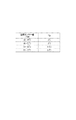
上記の点を鑑み、本実施形態では、図9に示すように複数の候補値の中からいずれかの値を選択し、それぞれの記録モードにおける閾値Tthとして設定する(ステップS503)。例えば、高速記録モードに相当する2パス記録の場合にはサブヒータの駆動を開始する閾値温度差Tthを3℃、標準記録モードに相当する4パス記録の場合に5℃、高画質記録モードに相当する8パス記録以上のモードにおいては10℃をそれぞれ選択する。なお、これらのそれぞれの記録モードにおける閾値Tth(℃)は適宜異なる値とすることができ、シミュレーション等によりそれぞれの記録モードで温度差を解消するために適する値を算出し、それらの値に関する情報を予め記録装置内のROM105に記憶させておくことができる。
In view of the above points, in the present embodiment, as shown in FIG. 9, one of a plurality of candidate values is selected and set as a threshold value Tth in each recording mode (step S503). For example, in the case of 2-pass printing corresponding to the high-speed recording mode, the threshold temperature difference Tth for starting the driving of the sub heater is 3 ° C., in the case of 4-pass printing corresponding to the standard recording mode, 5 ° C., corresponding to the high-quality recording mode. In the mode of 8 pass recording or higher, 10 ° C. is selected. Note that the threshold value Tth (° C.) in each of these recording modes can be set to different values as appropriate, and values suitable for eliminating the temperature difference in each recording mode are calculated by simulation or the like, and information on these values is obtained. Can be stored in advance in the
ステップS504にて主走査が開始されると、端部温度センサー53からの温度検出値と、中央部温度センサー54からの検出温度の差(温度差)ΔT(℃)を算出し、ステップS503にて設定された閾値Tth(℃)と比較を始める(ステップS505)。
When main scanning is started in step S504, a difference (temperature difference) ΔT (° C.) between the temperature detection value from the
温度差ΔT(℃)が閾値Tthよりも大きいと判断された場合、端部側と中央側の温度差を縮小するため、サブヒータの駆動が開始される(ステップS506)。一方、温度差ΔT(℃)が閾値Tth以下であると判断された場合、サブヒータは駆動されない(ステップS509)。その時点でサブヒータの駆動が実行されていた場合には、サブヒータの駆動が停止される。 When it is determined that the temperature difference ΔT (° C.) is larger than the threshold value Tth, the sub heater is started to reduce the temperature difference between the end and the center (step S506). On the other hand, when it is determined that the temperature difference ΔT (° C.) is equal to or smaller than the threshold value Tth, the sub heater is not driven (step S509). If driving of the sub-heater has been executed at that time, the driving of the sub-heater is stopped.
その後は画像記録が終了したか否かを判定し(ステップS507)、全てのデータの記録が終了していれば画像記録動作を終了する(ステップS508)。終了していない場合、ステップ102へと戻り、データが終了するまで同様の処理を続行する。 Thereafter, it is determined whether or not the image recording has been completed (step S507). If all the data has been recorded, the image recording operation is terminated (step S508). If not finished, the process returns to step 102 and the same processing is continued until the data is finished.
以下、高速記録モードで記録が行われた場合と標準記録モードで記録が行われた場合を例として、本実施形態を適用した際の温度推移について説明する。なお、ここでは例として、第1の実施形態と同様に記録する画像はA0サイズ ライトシアン100%デューティの画像であって、記録開始前にサブヒータとインクを吐出するために用いる電気熱変換素子を用いた温調制御によって記録開始前にヘッド温度を35℃に上昇させたのち、記録を開始する場合について記載する。
Hereinafter, temperature transition when the present embodiment is applied will be described by taking as an example a case where recording is performed in the high-speed recording mode and a case where recording is performed in the standard recording mode. Here, as an example, an image to be recorded is an A0 size
図9からわかるように、本実施形態において高速記録モードで記録を行う場合、閾値Tthは3℃に設定される。したがって、温度推移は図6(b)に示すように推移し、記録終了時には図7(b)に示すようにほぼ均一な温度分布とすることができる。 As can be seen from FIG. 9, when recording is performed in the high-speed recording mode in this embodiment, the threshold Tth is set to 3 ° C. Accordingly, the temperature transition changes as shown in FIG. 6B, and at the end of recording, a substantially uniform temperature distribution can be obtained as shown in FIG. 7B.
一方、図9からわかるように、標準記録モードで記録を行う場合、閾値Tthは5℃に設定される。ここで、図10は図6と同様の画像記録を標準記録モードにて記録した場合の温度推移を示す図である。 On the other hand, as can be seen from FIG. 9, when recording is performed in the standard recording mode, the threshold value Tth is set to 5 ° C. Here, FIG. 10 is a diagram showing a temperature transition when image recording similar to FIG. 6 is recorded in the standard recording mode.
図10(a)は本実施形態を適用しない場合における温度推移を示している。記録の終了する192秒後には、端部温度センサー値が約40℃、中央部温度センサー値が約47℃となった。 FIG. 10A shows a temperature transition when the present embodiment is not applied. 192 seconds after the end of recording, the end temperature sensor value was about 40 ° C. and the center temperature sensor value was about 47 ° C.
一方、図10(b)は本実施形態を適用した場合における温度推移を示している。記録が開始してから102秒後に端部温度センサー値と中央部温度センサー値との温度差が5℃を超えたため、サブヒータ17による加熱が開始されている。そのため、端部温度センサー値と中央部温度センサー値との温度差は縮小し、記録終了時点では温度差が約2℃となっている。ただし、サブヒータの加熱により記録ヘッド全体の温度もやや上昇したため、端部温度センサー値は約45.5℃、中央部温度センサー値は約47.5℃で記録を終了した。
On the other hand, FIG.10 (b) has shown the temperature transition at the time of applying this embodiment. Since the temperature difference between the end temperature sensor value and the central temperature sensor value exceeds 5 ° C. after 102 seconds from the start of recording, heating by the
図11は記録終了時点の吐出口列12の温度分布を示す図である。なお、図11(a)は本実施形態を適用しない場合における温度分布を、また、図11(b)は本実施形態を適用した場合における温度分布をそれぞれ示している。
FIG. 11 is a diagram showing the temperature distribution of the
本実施形態を適用しない場合、図11(a)に示すように、吐出口列の中央部の温度が高く、端部が低い温度分布である。これに対し、本実施形態を適用することにより、図11(b)に示すように吐出口列内のインクの温度分布はY方向においてほぼ均一となる。 When this embodiment is not applied, as shown in FIG. 11A, the temperature distribution is high in the central portion of the discharge port array and low in the end portion. On the other hand, by applying this embodiment, as shown in FIG. 11B, the temperature distribution of the ink in the ejection port array is substantially uniform in the Y direction.
このように、本実施形態によれば、単位領域に対する走査の回数に応じて異なる閾値を設定し、温度差が閾値より高い場合にサブヒータを駆動し、温度差が閾値以下となった場合にサブヒータの駆動を停止することで、吐出口列内(記録素子列内)の温度分布をほぼ均一にし、温度分布に由来する濃度むらを好適に抑制することが可能となる。高速記録モードでは走査の回数が少なく、吐出口列内の温度分布による濃度むらが視認されやすいが、本実施形態によれば中央部温度センサー値と端部温度センサー値との温度差が約1℃に低減することができる。これにより、吐出口列内の温度分布による濃度むらを効果的に抑制できる。一方、標準記録モードでは、高速記録モードよりマルチパス効果が得られやすいため、吐出口列内の温度分布が濃度ムラとして視認されにくい。そのため、本実施形態によれば中央部温度センサー値と端部温度センサー値との温度差が約2℃になるものの、濃度むらを効果的に抑制することができる。 As described above, according to the present embodiment, a different threshold is set according to the number of scans for the unit area, the sub-heater is driven when the temperature difference is higher than the threshold, and the sub-heater when the temperature difference is equal to or less than the threshold. By stopping this driving, the temperature distribution in the ejection port array (in the printing element array) can be made substantially uniform, and the density unevenness derived from the temperature distribution can be suitably suppressed. In the high-speed recording mode, the number of scans is small, and uneven density due to the temperature distribution in the ejection port array is easily visible. However, according to the present embodiment, the temperature difference between the center temperature sensor value and the end temperature sensor value is about 1. It can be reduced to ° C. Thereby, density unevenness due to temperature distribution in the ejection port array can be effectively suppressed. On the other hand, in the standard recording mode, the multi-pass effect is more easily obtained than in the high-speed recording mode, so that the temperature distribution in the ejection port array is not easily recognized as density unevenness. Therefore, according to this embodiment, although the temperature difference between the center temperature sensor value and the end temperature sensor value is about 2 ° C., density unevenness can be effectively suppressed.
また、高速記録モードにおいては、サブヒータ制御の実施により、サブヒータ制御を実施しない場合と比較して中央部温度センサー値が記録終了時点で約2℃上昇する結果となった。このような制御を継続し続けると、記録ヘッド全体が蓄熱し昇温するため、過昇温に伴う吐出不安定性を引き起こす可能性がある。そこで本実施形態の標準記録モードにおいては、サブヒータ制御を開始する閾値を高速記録モードよりも大きくすることでサブヒータ制御を実施する期間を最小限にとどめることができる。したがって、標準記録モードにおいては約0.5℃の上昇に抑制することが可能となる。 In the high-speed recording mode, the result of the sub-heater control was that the central temperature sensor value increased by about 2 ° C. at the end of recording as compared to the case where the sub-heater control was not performed. If such control is continued, the entire recording head accumulates heat and rises in temperature, which may cause ejection instability due to excessive temperature rise. Therefore, in the standard recording mode of the present embodiment, the period for performing the sub-heater control can be minimized by setting the threshold value for starting the sub-heater control larger than that in the high-speed recording mode. Accordingly, it is possible to suppress the increase to about 0.5 ° C. in the standard recording mode.
(第3の実施形態)
第2の実施形態では、記録条件として単位領域に対する走査の回数に応じてサブヒータを駆動するための閾値を決定する形態について記載した。
(Third embodiment)
In the second embodiment, a mode has been described in which a threshold value for driving the sub-heater is determined as a printing condition in accordance with the number of scans for the unit area.
これに対し、本実施形態では走査の回数以外の記録条件に応じてサブヒータを駆動するための閾値を決定する形態について記載する。 In contrast, in the present embodiment, a mode is described in which a threshold for driving the sub-heater is determined according to printing conditions other than the number of scans.
なお、前述した第1、第2の実施形態と同様の部分については説明を省略する。 The description of the same parts as those in the first and second embodiments described above will be omitted.
前述したように、吐出口列内の温度分布が同じであっても、記録媒体の種類や記録デューティ、記録を行う際の記録媒体の表面近傍における湿度に応じて温度分布に由来する濃度むらの程度は異なる虞がある。なお、本実施形態において記録デューティとは記録媒体上の単位領域に対してインクを吐出可能な画素領域の数に対する、実際にインクを吐出する画素領域の数の比率を指す。また、画素領域とは画素に相当する単位領域内の領域であり、同じ色のインクを最大で1滴だけ付与することができる領域を指す。例えば、100%の記録デューティの画像とは、単位領域内のすべての画素領域に対してインクを吐出して形成される、いわゆるベタ画像である。また、0%の記録デューティの画像とは、単位領域のいずれの画素領域にもインクを吐出しない画像である。このように、記録デューティは単位領域内に対して吐出するインクの吐出量に比例することがわかる。 As described above, even if the temperature distribution in the ejection port array is the same, the density unevenness derived from the temperature distribution depends on the type of recording medium, the recording duty, and the humidity in the vicinity of the surface of the recording medium at the time of recording. The degree may vary. Note that in this embodiment, the recording duty refers to the ratio of the number of pixel areas that actually eject ink to the number of pixel areas that can eject ink to a unit area on the recording medium. Further, the pixel area is an area in a unit area corresponding to a pixel, and refers to an area where a maximum of one drop of ink of the same color can be applied. For example, an image having a recording duty of 100% is a so-called solid image formed by ejecting ink to all the pixel regions in the unit region. An image with a recording duty of 0% is an image in which ink is not ejected to any pixel area of the unit area. Thus, it can be seen that the recording duty is proportional to the amount of ink ejected to the unit area.
例えば、普通紙、コート紙、光沢紙のうち、普通紙はインクの滲み易いため、温度分布に由来する濃度むら発生した場合であっても視認されにくい。一方、光沢紙はインクが滲みにくいため、温度分布に由来する濃度むらの視認性が高い。 For example, among plain paper, coated paper, and glossy paper, plain paper is likely to bleed ink, so that it is difficult to visually recognize even when density unevenness occurs due to temperature distribution. On the other hand, glossy paper has high visibility of uneven density due to temperature distribution because ink does not easily spread.
また、記録する画像が中間階調(例えば記録デューティが30〜50%)の場合、低階調(例えば記録デューティが0〜30%)の場合や高階調(例えば記録デューティが50〜100%)である場合に比べて記録位置がずれた際におけるインク滴の記録媒体上での被覆率の変動が大きい。そのため、中間階調においては温度分布に由来する濃度むらも高階調、低階調に比べて視認され易くなる。 Further, when the image to be recorded is an intermediate gradation (for example, recording duty is 30 to 50%), a low gradation (for example, recording duty is 0 to 30%) or a high gradation (for example, recording duty is 50 to 100%). Compared with the case where the recording position is shifted, the variation of the coverage of the ink droplet on the recording medium when the recording position is shifted is large. For this reason, the density unevenness derived from the temperature distribution is more likely to be visually recognized in the intermediate gradation compared to the high gradation and the low gradation.
更に、湿度が低い場合、湿度センサー(湿度検知手段)により検知された湿度が高い場合と記録媒体の吸湿度が異なり、インクが滲みにくくなる。そのため、温度分布に由来する濃度むらが発生した場合に視認され易い。 Further, when the humidity is low, the moisture absorption of the recording medium is different from that when the humidity detected by the humidity sensor (humidity detection means) is high, and the ink is difficult to bleed. Therefore, it is easy to visually recognize when density unevenness derived from the temperature distribution occurs.
以上の点を鑑み、本実施形態では図8のステップS502において記録条件に関する情報として、記録媒体の種類、記録デューティ、記録媒体の表面の近傍における湿度のいずれかに関する情報を取得する。そして、図8のステップS503において記録条件に応じて、適切な閾値を選択し、サブヒータの駆動制御を行う。 In view of the above points, in the present embodiment, information relating to any of the type of recording medium, the recording duty, and the humidity in the vicinity of the surface of the recording medium is acquired as information relating to the recording condition in step S502 of FIG. Then, in step S503 in FIG. 8, an appropriate threshold value is selected according to the printing condition, and sub-heater drive control is performed.
図12はサブヒータを駆動するための閾値を示すテーブル図である。なお、図12(a)、(b)、(c)はそれぞれ記録媒体の種類、記録デューティ、湿度に応じた適切な閾値を示している。 FIG. 12 is a table showing threshold values for driving the sub heater. FIGS. 12A, 12B, and 12C show appropriate threshold values according to the type of recording medium, recording duty, and humidity, respectively.
例えば、記録媒体の種類が濃度むらが目立ちにくい普通紙である場合には閾値は相対的に高く、また、濃度むらが目立ち易い光沢紙である場合には閾値は相対的に低くなるように設定される。また、濃度むらが目立ち易い中間階調の画像を記録する際には、高階調または低階調の画像を記録する際に比べて閾値が相対的に低くなるように設定される。また、湿度が低い場合には濃度むらが目立ち易いため、湿度が高い場合に比べて閾値が低くなるように設定される。 For example, the threshold value is set to be relatively high when the type of recording medium is plain paper with non-uniform density, and the threshold value is set to be relatively low when glossy paper with non-uniform density is easily noticeable. Is done. Further, when recording an intermediate gradation image in which density unevenness is conspicuous, the threshold is set to be relatively lower than when recording a high gradation or low gradation image. In addition, when the humidity is low, uneven density tends to be noticeable, so the threshold is set to be lower than that when the humidity is high.
本実施形態によれば、記録媒体の種類や記録デューティ、湿度によって温度分布に由来する濃度むらが目立ち易い場合であっても、濃度むらを好適に抑制した記録を行うことが可能となる。 According to the present embodiment, it is possible to perform recording in which density unevenness is suitably suppressed even when density unevenness derived from the temperature distribution is easily noticeable depending on the type of recording medium, recording duty, and humidity.
(第4の実施形態)
本実施形態では、温度センサーの検出温度に応じてサブヒータ制御を駆動する閾値温度差を設定する。
(Fourth embodiment)
In the present embodiment, a threshold temperature difference for driving the sub heater control is set according to the temperature detected by the temperature sensor.
なお、前述した第1から第3の実施形態と同様の部分については説明を省略する。 The description of the same parts as those in the first to third embodiments described above will be omitted.
図13は記録中の中央部温度センサーの検出温度に応じてサブヒータ制御を開始する閾値を設定する制御のフローを示すフローチャートである。 FIG. 13 is a flowchart showing a control flow for setting a threshold value for starting the sub-heater control in accordance with the temperature detected by the central temperature sensor during recording.
また、図14は温度センサーの検出温度に応じた適切な閾値温度を示すテーブル図である。 FIG. 14 is a table showing an appropriate threshold temperature corresponding to the temperature detected by the temperature sensor.
まずステップS1101にて画像記録が開始されると、中央部温度センサーの検出温度のうち、その時点での最高到達温度Tmax(℃)を取得する(ステップS1102)。Tmaxが61℃以上の場合には(ステップS1103)、サブヒータ制御開始フラグHonに0を設定する(ステップS1105)が、Tmaxが61℃未満の場合にはサブヒータ制御開始フラグHonに1を設定(ステップS1104)するとともにTmaxに応じたサブヒータ制御を開始する閾値Tthを図14に示すテーブルに基づいて設定する(ステップS1106)。 First, when image recording is started in step S1101, the maximum temperature Tmax (° C.) at that time among the temperatures detected by the central temperature sensor is acquired (step S1102). If Tmax is 61 ° C. or higher (step S1103), 0 is set to the sub-heater control start flag Hon (step S1105). If Tmax is less than 61 ° C., 1 is set to the sub-heater control start flag Hon (step S1105). S1104) and a threshold value Tth for starting sub-heater control according to Tmax is set based on the table shown in FIG. 14 (step S1106).
主走査が開始される(ステップS1107)と同時に、サブヒータ制御開始フラグの状態を確認するとともに、端部温度センサー53からの温度検出値と、中央部温度センサー54からの温度検出値との差ΔT(℃)をステップS1106で設定した閾値Tth(℃)と比較を始める(ステップS1108)。サブヒータ制御開始フラグHonが1で、且つ中央部温度センサーの最高到達温度から設定された閾値Tth(℃)よりも、温度検出値の差ΔT(℃)が大きくなったことを検知すると、端部温度センサーと中央部温度センサー間の温度差を小さくするようにサブヒータの制御が開始されるようになっている(ステップS1109)。一方、温度差ΔTが閾値Tth以下である場合にはサブヒータの駆動が停止される(ステップS1112)。
Simultaneously with the start of the main scanning (step S1107), the state of the sub heater control start flag is confirmed, and the difference ΔT between the temperature detection value from the
その後は画像記録が終了したか否かを判定し(ステップS1110)、全てのデータの記録が終了していれば画像記録動作を終了するようになっている(ステップS1111)。 Thereafter, it is determined whether or not the image recording has been completed (step S1110). If all the data has been recorded, the image recording operation is terminated (step S1111).
以上の制御によれば、吐出口列の温度が低く、高デューティの画像の記録を行った場合に急激に中央部と端部の温度差が広がる懸念ある条件においては早めにサブヒータ制御を開始し、濃度むらの発生を回避することが可能である。一方、吐出口列の温度が高く、支持基板も含めて蓄熱しているような場合には、高デューティの画像の記録を行っても急激に温度差が広がる可能性は小さい。そのためサブヒータ制御を予め開始しておく必要はなく、濃度むらの発生しない程度の温度差までサブヒータ制御の開始を遅延させ、ヘッドの過昇温を防止することができる。また、吐出口列の温度が過昇温の虞がある温度領域に到達しそうな場合(本実施形態においては61℃以上)には、サブヒータの駆動は行わず、記録ヘッドの吐出性能を優先することが可能である。 According to the above control, when the temperature of the discharge port array is low and a high-duty image is recorded, sub-heater control is started early under conditions where the temperature difference between the central portion and the end portion may suddenly widen. It is possible to avoid the occurrence of density unevenness. On the other hand, when the temperature of the discharge port array is high and heat is stored including the support substrate, there is little possibility that the temperature difference will suddenly widen even if high duty image recording is performed. Therefore, it is not necessary to start the sub-heater control in advance, and the start of the sub-heater control can be delayed until the temperature difference is such that density unevenness does not occur, thereby preventing the head from being overheated. Further, when the temperature of the ejection port array is likely to reach a temperature region where there is a risk of overheating (in this embodiment, 61 ° C. or higher), the sub-heater is not driven and priority is given to the ejection performance of the recording head. It is possible.
図15は中央部温度センサー値が41℃の場合と、51℃の場合に、第1の実施形態と同様の高速記録モード記録を実施した場合の記録開始後2走査分の温度推移を示す図である。 FIG. 15 is a diagram showing temperature transitions for two scans after the start of recording when the central temperature sensor value is 41 ° C. and 51 ° C. when high-speed recording mode recording similar to that of the first embodiment is performed. It is.
図15(a)は中央部温度センサー値が41℃の状態から記録を始めた場合の中央部温度センサー値と端部温度センサー値の推移である。記録開始後まもなく、温度センサー間の温度差は2℃を超え、1走査目の終了時点で端部温度センサー値は47℃、中央部温度センサー値は52℃まで温度上昇した。従って、高速記録モードにて濃度ムラが視認される温度差4℃を超えてしまう。そこで本実施形態により温度差が2℃になった時点でサブヒータ制御を開始すれば、記録中の温度差拡大を抑制することができる。本実施形態においては約3℃の温度差とすることができた。 FIG. 15A shows the transition of the central temperature sensor value and the end temperature sensor value when recording starts from a state where the central temperature sensor value is 41 ° C. Shortly after the start of recording, the temperature difference between the temperature sensors exceeded 2 ° C., and at the end of the first scan, the end temperature sensor value increased to 47 ° C. and the central temperature sensor value increased to 52 ° C. Therefore, the temperature difference at which the density unevenness is visually recognized in the high-speed recording mode exceeds 4 ° C. Therefore, if the sub-heater control is started when the temperature difference becomes 2 ° C. according to the present embodiment, it is possible to suppress the temperature difference expansion during recording. In this embodiment, a temperature difference of about 3 ° C. could be achieved.
一方、図15(b)は中央部温度センサーが51℃の状態から記録を始めた場合の温度推移である。記録開始時点で記録ヘッド自体が蓄熱しているため、記録による温度上昇推移は緩やかで、記録終了時点でも温度センサー間の温度差は約2.5℃に留まった。したがって記録開始温度が41℃の場合と同じように温度差が2℃になった時点で即座にサブヒータ制御を開始する必要はない。本実施例においては濃度むら懸念のある約4℃になる手前の3.5℃からサブヒータの制御を開始する閾値としたため2走査の記録においてはサブヒータを駆動することがなく、記録ヘッドの更なる過昇温を防止することができた。 On the other hand, FIG. 15B shows a temperature transition when recording is started from a state where the central temperature sensor is 51 ° C. Since the recording head itself stores heat at the start of recording, the temperature rise due to recording is gradual, and the temperature difference between the temperature sensors remains at about 2.5 ° C. even at the end of recording. Accordingly, it is not necessary to immediately start the sub-heater control when the temperature difference becomes 2 ° C., as in the case where the recording start temperature is 41 ° C. In this embodiment, since the threshold value for starting the control of the sub-heater is set at 3.5 ° C., which is about 4 ° C. at which there is a possibility of density unevenness, the sub-heater is not driven in two-scan printing, and the print head is further increased. Overheating could be prevented.
以上説明した通り、本発明実施により吐出口列内の温度分布を解消し、濃度ムラを回避できるだけでなく、記録ヘッドの過昇温を防止して吐出性能の低下を抑制することが可能である。 As described above, by implementing the present invention, it is possible not only to eliminate the temperature distribution in the ejection port array and avoid density unevenness, but also to prevent excessive temperature rise of the recording head and suppress a decrease in ejection performance. .
なお、本実施形態においては中央部温度センサー値の温度に応じてサブヒータ制御を開始する閾値温度差を設定する構成としたが、端部温度センサーの値を用いたり、全く別の温度センサーを用いてもよく、記録条件として吐出口列近傍の温度が検出できればどのようなセンサー値を用いてもよい。 In this embodiment, the threshold temperature difference for starting the sub-heater control is set according to the temperature of the center temperature sensor value. However, the end temperature sensor value or a completely different temperature sensor is used. Any sensor value may be used as long as the temperature in the vicinity of the ejection port array can be detected as the recording condition.
また、本実施形態においては記録ヘッドに過昇温の危険性がある場合にサブヒータ制御を実施しない構成としたが、サブヒータの駆動デューティを下げたり、駆動時間を減らすなど、サブヒータへの投入エネルギーを減らす構成とすれば同様の効果が得られるものである。 In this embodiment, the sub-heater control is not performed when there is a risk of overheating of the recording head. However, the input energy to the sub-heater is reduced by reducing the driving duty of the sub-heater or reducing the driving time. If the configuration is reduced, the same effect can be obtained.
(第5の実施形態)
本実施形態では、サブヒータを駆動する閾値温度差と、停止する閾値温度差とを異なる閾値とする。
(Fifth embodiment)
In this embodiment, the threshold temperature difference for driving the sub-heater and the threshold temperature difference for stopping are set as different threshold values.
なお、前述した第1から第4の実施形態と同様の部分については説明を省略する。 The description of the same parts as those in the first to fourth embodiments described above will be omitted.
図16はサブヒータ制御を開始する閾値温度差と、停止する閾値温度差とを異なる閾値とする制御のフローを説明するフローチャートである。 FIG. 16 is a flowchart for explaining a control flow in which a threshold temperature difference for starting sub-heater control and a threshold temperature difference for stopping are different threshold values.
まずステップS1401にて画像記録が開始されると、MPU102ではROM105からの情報に基づいて、単位領域に対する走査の回数に関する情報を取得する。(ステップS1402)。次に図17に示す通り、走査回数に対応する各記録モードにおけるサブヒータ制御を開始する閾値温度差Tthonと、サブヒータ制御を停止する閾値温度差(所定値)Tthoffとの設定テーブルを参照し、当該記録モードにおける閾値温度差を設定する(ステップS1403)。ここで、それぞれの記録モードにおいて、サブヒータ制御を停止する閾値温度差Tthoffは、サブヒータ制御を開始する閾値温度差Tthonよりも低くなるように設定されている。
First, when image recording is started in step S1401, the
主走査が開始される(ステップS1404)と同時に、端部温度センサー53からの温度検出値と、中央部温度センサー54からの温度検出値との差ΔT(℃)をステップS1403で設定した閾値Tthon(℃)と比較を始める(ステップS1405)。記録モードから設定された閾値Tthon(℃)に対して、温度検出値の差ΔT(℃)が大きくなったことを検知すると、端部温度センサーと中央部温度センサー間の温度差を縮小すべくサブヒータが駆動されるようになっている(ステップS1406)。次に、温度検出値の差ΔT(℃)がステップ1403で設定した閾値Tthoff以下(所定値以下)となったか否かを判定し(ステップS1407)、Thoff以下となったことを検知すると、サブヒータを停止する(ステップS1408)。
Simultaneously with the start of the main scanning (step S1404), the threshold value Tthon in which the difference ΔT (° C.) between the temperature detection value from the
その後は画像記録が終了したか否かを判定し(ステップS1409)、全てのデータの記録が終了していれば画像記録動作を終了するようになっている(ステップS1410)。 Thereafter, it is determined whether or not the image recording has been completed (step S1409). If all the data has been recorded, the image recording operation is terminated (step S1410).
以上の制御によれば、サブヒータ駆動温度とサブヒータ停止温度が同じ場合と比較してサブヒータによる加熱時間を十分に確保でき、吐出口列中央部と端部の温度差を均一化する効果が得られやすい。例えば、図18(a)は実施例1と同様のA0サイズ ライトシアン100%デューティの画像の記録を高速記録モードにて実施する場合に、サブヒータの駆動温度と停止温度とが同じ設定の場合(この場合3℃)の温度推移である。中央部温度センサー値と端部温度センサー値の差は記録開始34秒後に3℃となり、サブヒータの駆動が開始される。ところが、サブヒータによる加熱効果で端部温度センサー値は一瞬上昇し、その結果温度差が3℃未満となってしまうため、直後にサブヒータは停止する。以降、サブヒータは制御ONとOFFを繰り返し、端部温度センサー値と中央部温度センサー値の温度差はほとんど縮小することなく約3℃のまま記録を終了した。
According to the above control, the heating time by the sub heater can be sufficiently secured as compared with the case where the sub heater driving temperature and the sub heater stop temperature are the same, and the effect of equalizing the temperature difference between the central portion and the end portion of the discharge port array can be obtained. Cheap. For example, FIG. 18A shows a case in which the same setting of the A0 size
一方、図18(b)は図17に示す通り、サブヒータ制御を停止する閾値Tthoff(℃)をサブヒータ制御を開始する閾値Tthon(℃)よりも低く設定した場合の温度推移である。記録開始34秒後に温度差が3℃となり、Tthon(℃)を超えたためサブヒータ制御が開始されている。その後サブヒータの加熱効果により端部温度センサー値は上昇し、中央部温度センサー値との温度差は3℃未満となるが、Tthoff(℃)を下回らないためサブヒータ制御は引き続き継続される。記録開始後56秒後に温度差は1℃を下回ったため、サブヒータ制御は停止される。サブヒータ制御が停止したため、端部温度センサー値の上昇は停滞し中央部温度センサー値との温度差は拡大するものの、3℃以内のまま記録を終了したためサブヒータ制御は再開することがなかった。記録終了時点での温度差は約1.5℃となり、サブヒータ制御の開始温度と停止温度が同じ設定の場合と比較して温度差は縮小した。 On the other hand, FIG. 18B shows the temperature transition when the threshold value Tthoff (° C.) for stopping the sub-heater control is set lower than the threshold value Tthon (° C.) for starting the sub-heater control, as shown in FIG. Since the temperature difference became 3 ° C. 34 seconds after the start of recording and exceeded Tthon (° C.), the sub-heater control was started. Thereafter, the end temperature sensor value rises due to the heating effect of the sub heater, and the temperature difference from the central temperature sensor value is less than 3 ° C., but the sub heater control is continued because it does not fall below Tthoff (° C.). The sub-heater control is stopped because the temperature difference is less than 1 ° C. 56 seconds after the start of recording. Since the sub-heater control was stopped, the rise in the end temperature sensor value stagnated and the temperature difference from the central temperature sensor value was enlarged, but the recording was finished within 3 ° C., so the sub-heater control was not resumed. The temperature difference at the end of recording was about 1.5 ° C., and the temperature difference was reduced as compared with the case where the sub heater control start temperature and stop temperature were set to the same setting.
このように、サブヒータ制御を停止する閾値温度差Tthoffをサブヒータ制御を開始する閾値温度差Tthonよりも低く設定とすることで、頻繁なサブヒータのON/OFF制御によって加熱時間が不足させず、サブヒータ制御を十分継続できるため吐出口列中央部と端部の温度差を縮小しやすくなる。また、図15に示す通り、単位領域に対する走査の回数に応じてサブヒータ制御を開始する閾値Tthon(℃)と停止する閾値Tthoff(℃)との差を変更することができる。これにより、濃度ムラの発生懸念の高い場合にはサブヒータ制御を十分長い時間継続できるようにし、濃度ムラの発生懸念の低い場合においてはサブヒータ制御を最小限とすることで記録ヘッドの過昇温を防ぐなど、最適制御が可能である。 In this way, by setting the threshold temperature difference Tthoff for stopping the sub-heater control to be lower than the threshold temperature difference Tthon for starting the sub-heater control, the sub-heater control can be performed without insufficient heating time by frequent ON / OFF control of the sub-heater. Therefore, the temperature difference between the central portion and the end portion of the discharge port array can be easily reduced. Further, as shown in FIG. 15, the difference between the threshold value Tthon (° C.) at which the sub-heater control is started and the threshold value Tthoff (° C.) at which the sub-heater control is stopped can be changed according to the number of scans for the unit area. As a result, the sub-heater control can be continued for a sufficiently long time when there is a high concern about the occurrence of density unevenness, and the sub-heater control is minimized when the possibility of occurrence of density unevenness is low. Optimal control is possible, such as prevention.
以上説明したように、本実施形態によれば、吐出口列内の温度分布を均一にし、濃度むらを抑制できるだけでなく、記録ヘッドの過昇温による吐出性能の低下を抑制することも可能である。 As described above, according to the present embodiment, not only can the temperature distribution in the ejection port array be made uniform and density unevenness can be suppressed, but also deterioration in ejection performance due to overheating of the recording head can be suppressed. is there.
なお、本実施形態では単位領域に対する走査の回数に応じてサブヒータ開始温度と停止温度を設定する構成としたが、他の形態による実施も可能である。例えば、記録媒体の種類や、記録デューティ、記録媒体の表面近傍における湿度、吐出口列内のインクの温度に応じてサブヒータ開始温度と停止温度を設定する構成であっても良い。第1の実施形態と同様に予め定められた閾値を用いる形態においてもサブヒータ制御の開始温度と停止温度を異ならせても良い。 In the present embodiment, the sub-heater start temperature and the stop temperature are set according to the number of scans with respect to the unit area. However, other embodiments are also possible. For example, the sub heater start temperature and stop temperature may be set according to the type of recording medium, the recording duty, the humidity near the surface of the recording medium, and the temperature of the ink in the ejection port array. Similarly to the first embodiment, the start temperature and the stop temperature of the sub heater control may be made different in the form using a predetermined threshold value.
また、以上に説明した各実施形態では、サブヒータが吐出口列11〜13を取り囲むように配置された形態の記録ヘッドを用いたが、他の形態による実施も可能である。吐出口近傍に複数のサブヒータを配置するなど、吐出口列の端部温度と中央部温度の温度差を小さくするような形態であれば同様の効果が得られるものである。
Further, in each of the embodiments described above, the recording head having a form in which the sub-heater is disposed so as to surround the
また、以上で説明した各実施形態では、サブヒータを常に温度差に応じて駆動制御する形態について記載したが、他の形態による実施も可能である。例えば、従来のように温度が顕著に低い場合に生じる吐出量の低下や不吐などを抑制するため、検出された温度が所定の閾値以下の場合にサブヒータを駆動し、所定の閾値より高くなった際にサブヒータの駆動を停止する形態と組み合わせても良い。この場合、例えば(i)検出された温度が40℃以下である場合にはサブヒータを駆動し、(ii)検出された温度が40℃より高く、且つ、温度差が3℃以下の場合にはサブヒータの駆動を停止し、(iii)検出された温度が40℃より高く、且つ、温度差が3℃より大きい場合に温度差を解消するためにサブヒータを再度駆動するような形態であっても良い。なお、この場合の温度としては端部温度センサー、中央部温度センサーのどちらか一方の値を使用して代表温度としても良いし、2つの値の平均値を参照して代表温度としても良い。 In each of the embodiments described above, the sub-heater is always driven and controlled according to the temperature difference. However, other embodiments are also possible. For example, the sub heater is driven when the detected temperature is equal to or lower than a predetermined threshold in order to suppress a decrease in discharge amount or non-discharge, which occurs when the temperature is significantly low as in the past, and becomes higher than the predetermined threshold. It may be combined with a mode in which the driving of the sub-heater is stopped at the time. In this case, for example, (i) when the detected temperature is 40 ° C. or lower, the sub heater is driven, and (ii) when the detected temperature is higher than 40 ° C. and the temperature difference is 3 ° C. or lower. Even if the driving of the sub-heater is stopped and (iii) the detected temperature is higher than 40 ° C. and the temperature difference is larger than 3 ° C., the sub-heater is driven again to eliminate the temperature difference. good. In this case, as the temperature in this case, either the end temperature sensor or the center temperature sensor may be used as the representative temperature, or the representative temperature may be referred to by referring to the average value of the two values.
また、以上で説明した各実施形態では、記録媒体に対して複数回の走査を行うことにより画像を記録する形態について記載したが、他の形態による実施も可能である。例えば、記録媒体の幅方向よりも長い長さを有する長尺な記録ヘッドを用い、幅方向と交差する方向に記録媒体を1回だけ搬送させながら記録ヘッドからインクを吐出して画像を記録する形態であっても各実施形態を適用することができる。 Further, in each of the embodiments described above, the form in which an image is recorded by performing scanning a plurality of times on the recording medium has been described. However, other forms are possible. For example, a long recording head having a length longer than the width direction of the recording medium is used, and an image is recorded by ejecting ink from the recording head while transporting the recording medium only once in a direction crossing the width direction. Each embodiment can be applied even if it is a form.
また、以上に記載した各実施形態における制御を組み合わせて実行することも可能である。例えば、記録条件として単位領域に対する走査の回数と中央部温度センサーの値の両方に応じてサブヒータの駆動を制御しても良い。この場合、図13に示すサブヒータの駆動制御において、サブヒータ制御開始フラグHonが1である場合、ステップS1106において、図19(a)、(b)、(c)それぞれに示す単位領域に対する走査の回数および中央部温度センサーの値に応じてサブヒータを駆動するための閾値を定めたテーブルにしたがって閾値Tthを決定すればよい。 It is also possible to execute a combination of the controls in the embodiments described above. For example, the driving of the sub-heater may be controlled in accordance with both the number of scans for the unit area and the value of the central temperature sensor as the printing condition. In this case, in the sub-heater drive control shown in FIG. 13, when the sub-heater control start flag Hon is 1, in step S1106, the number of scans for the unit regions shown in FIGS. 19A, 19B, and 19C, respectively. The threshold value Tth may be determined according to a table in which threshold values for driving the sub-heaters are determined according to the value of the central temperature sensor.
また、各実施形態には画像記録装置および画像記録方法について記載したが、各実施形態に記載の画像記録方法を行うためのデータを生成する画像処理装置や画像処理方法であっても良い。更に、本発明は画像記録装置を機能させるプログラムを画像記録装置とは別体に用意する形態や画像記録装置の一部に備える形態等、広く適用することができる。 In each embodiment, the image recording apparatus and the image recording method are described. However, an image processing apparatus and an image processing method that generate data for performing the image recording method described in each embodiment may be used. Furthermore, the present invention can be widely applied to a form in which a program for causing an image recording apparatus to function is prepared separately from the image recording apparatus or a form provided in a part of the image recording apparatus.
9 記録ヘッド
11−16 吐出口列
17 サブヒータ
53、54 温度センサー
105 ROM
9 Recording head 11-16
Claims (19)
画像を記録する際の記録条件に関する情報を取得する取得手段と、
前記取得手段によって取得された前記情報に基づいて第1の閾値を決定する決定手段と、
前記第1の検知素子により検知された温度と、前記第2の検知素子により検知された温度と、の差が前記第1の閾値よりも大きい場合に前記加熱素子による加熱を実行するように、前記加熱素子を制御する制御手段と、
を有することを特徴とする画像記録装置。 A substrate, a recording element array in which a plurality of recording elements for generating thermal energy for ejecting ink of a predetermined color are arranged in a predetermined direction on the substrate, and a first in the predetermined direction in the recording element array A first detection element for detecting the temperature in the vicinity of the recording element at the position, and a temperature in the vicinity of the recording element in the second position that is closer to the center of the recording element array than the first position in the predetermined direction. For recording an image on a recording medium using a recording head having a second detecting element for detecting the ink and a heating element for heating at least the ink in the vicinity of the recording element at the first position An image recording device,
Acquisition means for acquiring information relating to recording conditions when recording an image;
Determining means for determining a first threshold based on the information acquired by the acquiring means;
When the difference between the temperature detected by the first detection element and the temperature detected by the second detection element is larger than the first threshold, heating by the heating element is performed. Control means for controlling the heating element;
An image recording apparatus comprising:
前記決定手段は、前記取得手段により取得された前記情報が示す走査の回数が第1の回数である場合、第1の値を前記第1の閾値に決定し、前記取得手段により取得された前記情報が示す走査の回数が前記第1の回数よりも少ない第2の回数である場合、前記第1の値よりも小さい第2の値を前記第1の閾値に決定することを特徴とする請求項1から3のいずれか1項に記載の画像記録装置。 The recording head can scan a unit area on the recording medium a plurality of times, and the information on the recording condition acquired by the acquisition unit includes information on the number of scans of the recording head with respect to the unit area. Including
The determination unit determines a first value as the first threshold when the number of scans indicated by the information acquired by the acquisition unit is a first number, and the acquisition unit acquires the first value. The second value smaller than the first value is determined as the first threshold value when the number of scans indicated by the information is a second number smaller than the first number. Item 4. The image recording apparatus according to any one of Items 1 to 3.
前記決定手段は、前記取得手段により取得された前記情報が示すインクの量が第1の量である場合、第3の値を前記第1の閾値に決定し、前記取得手段により取得された前記情報が示すインクの量が前記第1の量よりも少ない第2の量である場合、前記第3の値よりも小さい第4の値を前記第1の閾値に決定することを特徴とする請求項1から3のいずれか1項に記載の画像記録装置。 The information related to the recording condition acquired by the acquiring means includes information related to the amount of ink ejected to the unit area on the recording medium,
The determining unit determines a third value as the first threshold value when the amount of ink indicated by the information acquired by the acquiring unit is a first amount, and the acquired by the acquiring unit The fourth value smaller than the third value is determined as the first threshold when the amount of ink indicated by the information is a second amount smaller than the first amount. Item 4. The image recording apparatus according to any one of Items 1 to 3.
前記決定手段は、前記取得手段により取得された前記情報が示す記録媒体の種類が普通紙である場合、第6の値を前記第1の閾値に決定し、前記取得手段により取得された前記情報が示す記録媒体の種類がコート紙である場合、前記第6の値よりも小さい第7の値を前記第1の閾値に決定することを特徴とする請求項1から3のいずれか1項に記載の画像記録装置。 The information on the recording condition acquired by the acquisition means includes information on the type of recording medium,
The determination unit determines a sixth value as the first threshold value when the type of the recording medium indicated by the information acquired by the acquisition unit is plain paper, and the information acquired by the acquisition unit 4. The method according to claim 1, wherein when the type of the recording medium indicated by is a coated paper, a seventh value smaller than the sixth value is determined as the first threshold value. 5. The image recording apparatus described.
前記決定手段は、前記取得手段により取得された前記情報が示す記録媒体の種類が普通紙である場合、第9の値を前記第1の閾値に決定し、前記取得手段により取得された前記情報が示す記録媒体の種類が光沢紙である場合、前記第9の値よりも小さい第10の値を前記第1の閾値に決定することを特徴とする請求項1から3のいずれか1項に記載の画像記録装置。 The information on the recording condition acquired by the acquisition means includes information on the type of recording medium,
The determination unit determines a ninth value as the first threshold when the type of the recording medium indicated by the information acquired by the acquisition unit is plain paper, and the information acquired by the acquisition unit 4. The tenth value smaller than the ninth value is determined as the first threshold value when the type of the recording medium indicated by is glossy paper. 5. The image recording apparatus described.
前記取得手段により取得される前記記録条件に関する情報は、前記湿度検知手段により検知された湿度に関する情報を含み、
前記決定手段は、前記取得手段により取得された前記情報が示す湿度が第1の湿度である場合、第11の値を前記第1の閾値に決定し、前記取得手段により取得された前記情報が示す湿度が前記第1の湿度よりも低い第2の湿度である場合、前記第11の値よりも小さい第12の値を前記第1の閾値に決定することを特徴とする請求項1から3のいずれか1項に記載の画像記録装置。 Further comprising humidity detecting means for detecting humidity in the vicinity of the surface of the recording medium when ink is ejected to the recording medium;
The information on the recording condition acquired by the acquisition unit includes information on the humidity detected by the humidity detection unit,
The determining unit determines an eleventh value as the first threshold when the humidity indicated by the information acquired by the acquiring unit is a first humidity, and the information acquired by the acquiring unit is The twelfth value smaller than the eleventh value is determined as the first threshold value when the indicated humidity is the second humidity lower than the first humidity. The image recording apparatus according to any one of the above.
前記決定手段は、前記取得手段により取得された前記情報が示す温度が第1の温度である場合、第13の値を前記第1の閾値に決定し、前記取得手段により取得された前記情報が示す温度が前記第1の温度よりも低い第2の温度である場合、前記第13の値よりも小さい第14の値を前記第1の閾値に決定することを特徴とする請求項1から3のいずれか1項に記載の画像記録装置。 The information related to the recording condition acquired by the acquisition means includes information related to any one of the temperature detected by the first detection element and the temperature detected by the second detection element. Including
The determination unit determines a thirteenth value as the first threshold when the temperature indicated by the information acquired by the acquisition unit is a first temperature, and the information acquired by the acquisition unit is The 14th value smaller than the 13th value is determined as the 1st threshold when the temperature to show is the 2nd temperature lower than the 1st temperature. The image recording apparatus according to any one of the above.
前記制御手段は、前記第2の取得手段によって取得された代表温度が第3の閾値以下である場合に前記加熱素子による加熱を実行し、前記第2の取得手段によって取得された代表温度が前記第3の閾値よりも高く、且つ、前記差が前記第1の閾値よりも大きい場合に前記加熱素子による加熱を実行し、前記第2の取得手段によって取得された代表温度が前記第3の閾値よりも高く、且つ、前記差が前記第2の閾値以下である場合に前記加熱素子による加熱を停止するように、前記加熱素子による加熱を制御することを特徴とする請求項13から15のいずれか1項に記載の画像記録装置。 A second acquisition means for acquiring a representative temperature based on the temperature detected by the first detection element and the temperature detected by the second detection element;
The control unit performs heating by the heating element when the representative temperature acquired by the second acquisition unit is equal to or lower than a third threshold, and the representative temperature acquired by the second acquisition unit is Heating by the heating element is performed when the difference is higher than a third threshold and the difference is larger than the first threshold, and the representative temperature acquired by the second acquisition means is the third threshold. The heating by the heating element is controlled so as to stop the heating by the heating element when the difference is equal to or higher than the second threshold value and less than the second threshold value. The image recording apparatus according to claim 1.
画像を記録する際の記録条件に関する情報を取得する取得工程と、
前記取得工程において取得された前記情報に基づいて第1の閾値を決定する決定工程と、
前記第1の検知素子により検知された温度と、前記第2の検知素子により検知された温度と、の差が第1の閾値よりも大きい場合に前記加熱素子による加熱を実行するように、前記加熱素子を制御する制御工程と、
を有することを特徴とする制御方法。 A substrate, a recording element array in which a plurality of recording elements for generating thermal energy for ejecting ink of a predetermined color are arranged in a predetermined direction on the substrate, and a first in the predetermined direction in the recording element array A first detection element for detecting the temperature in the vicinity of the recording element at the position, and a temperature in the vicinity of the recording element in the second position that is closer to the center of the recording element array than the first position in the predetermined direction. For recording an image on a recording medium using a recording head having a second detecting element for detecting the ink and a heating element for heating at least the ink in the vicinity of the recording element at the first position A method for controlling an image recording apparatus, comprising:
An acquisition step of acquiring information regarding recording conditions when recording an image;
A determination step of determining a first threshold based on the information acquired in the acquisition step ;
The heating by the heating element is performed when the difference between the temperature detected by the first detection element and the temperature detected by the second detection element is greater than a first threshold. A control process for controlling the heating element;
A control method characterized by comprising:
Priority Applications (1)
| Application Number | Priority Date | Filing Date | Title |
|---|---|---|---|
| JP2015107878A JP6598514B2 (en) | 2014-05-27 | 2015-05-27 | Image recording apparatus, control method, and program |
Applications Claiming Priority (3)
| Application Number | Priority Date | Filing Date | Title |
|---|---|---|---|
| JP2014109047 | 2014-05-27 | ||
| JP2014109047 | 2014-05-27 | ||
| JP2015107878A JP6598514B2 (en) | 2014-05-27 | 2015-05-27 | Image recording apparatus, control method, and program |
Publications (3)
| Publication Number | Publication Date |
|---|---|
| JP2016005905A JP2016005905A (en) | 2016-01-14 |
| JP2016005905A5 JP2016005905A5 (en) | 2018-07-05 |
| JP6598514B2 true JP6598514B2 (en) | 2019-10-30 |
Family
ID=54700800
Family Applications (1)
| Application Number | Title | Priority Date | Filing Date |
|---|---|---|---|
| JP2015107878A Active JP6598514B2 (en) | 2014-05-27 | 2015-05-27 | Image recording apparatus, control method, and program |
Country Status (2)
| Country | Link |
|---|---|
| US (1) | US9315058B2 (en) |
| JP (1) | JP6598514B2 (en) |
Families Citing this family (4)
| Publication number | Priority date | Publication date | Assignee | Title |
|---|---|---|---|---|
| JP6333200B2 (en) * | 2015-03-05 | 2018-05-30 | キヤノン株式会社 | Inkjet recording apparatus, inkjet recording method, and recording head |
| US10076902B2 (en) * | 2016-05-27 | 2018-09-18 | Canon Kabushiki Kaisha | Print element substrate, liquid ejection head, and printing device |
| US9862187B1 (en) * | 2016-08-22 | 2018-01-09 | RF Printing Technologies LLC | Inkjet printhead temperature sensing at multiple locations |
| JP7025265B2 (en) * | 2018-03-29 | 2022-02-24 | キヤノン株式会社 | Image forming device and its control method |
Family Cites Families (5)
| Publication number | Priority date | Publication date | Assignee | Title |
|---|---|---|---|---|
| JP2984380B2 (en) | 1991-01-18 | 1999-11-29 | キヤノン株式会社 | Ink jet recording device |
| ATE187933T1 (en) * | 1993-05-27 | 2000-01-15 | Canon Kk | APPARATUS AND METHOD FOR CONTROLLING INKJET RECORDING DEVICES DEPENDENT ON THE EXPECTED TEMPERATURE |
| JPH08252926A (en) * | 1995-03-17 | 1996-10-01 | Canon Inc | Recording head and recording apparatus using the same |
| JP2005035080A (en) * | 2003-07-17 | 2005-02-10 | Fuji Xerox Co Ltd | Recording head and recorder |
| KR20060135452A (en) * | 2005-06-25 | 2006-12-29 | 삼성전자주식회사 | Printing apparatus with head chip spitting ink and head chip temperature control method thereof |
-
2015
- 2015-05-26 US US14/721,327 patent/US9315058B2/en active Active
- 2015-05-27 JP JP2015107878A patent/JP6598514B2/en active Active
Also Published As
| Publication number | Publication date |
|---|---|
| JP2016005905A (en) | 2016-01-14 |
| US9315058B2 (en) | 2016-04-19 |
| US20150343817A1 (en) | 2015-12-03 |
Similar Documents
| Publication | Publication Date | Title |
|---|---|---|
| JP6333200B2 (en) | Inkjet recording apparatus, inkjet recording method, and recording head | |
| JP5072573B2 (en) | Recording apparatus and recording head control method | |
| JP4182123B2 (en) | Inkjet recording head and inkjet recording apparatus | |
| JP6598514B2 (en) | Image recording apparatus, control method, and program | |
| US8740329B2 (en) | Inkjet printing apparatus and method for controlling drive of nozzles in inkjet printing apparatus | |
| JP7549472B2 (en) | Recording device, control method, storage medium, and program | |
| US20160339693A1 (en) | Ink jet printing apparatus and method for controlling inkjet printing apparatus | |
| JP5224968B2 (en) | Inkjet recording apparatus and inkjet recording method | |
| JP2009279817A (en) | Recording device and recording method | |
| US8985721B2 (en) | Printing apparatus and aging method | |
| US8474941B2 (en) | Inkjet printing apparatus and inkjet printing method | |
| JP4632416B2 (en) | Inkjet recording apparatus and inkjet recording method | |
| JP7614787B2 (en) | Inkjet recording apparatus, control method and program | |
| US9873247B2 (en) | Ink jet printing apparatus and ink jet printing method | |
| JP6300551B2 (en) | Liquid ejection device and liquid ejection method | |
| JP4280453B2 (en) | Recording apparatus and recording head temperature management method | |
| JP6579833B2 (en) | Liquid ejection apparatus and method for maintaining heat of liquid ejection head | |
| JP2023067249A (en) | Recording device and control method | |
| US9662876B2 (en) | Liquid ejecting apparatus and method of forming adjustment pattern check area | |
| JP2001001599A (en) | Printing device, information processing device and information processing system | |
| JP2005022271A (en) | Recording method and recording device | |
| JP2003039641A (en) | Ink jet recorder and ink jet recording method | |
| JP2006043923A (en) | Recorder | |
| JP2006159875A (en) | Ink jet recorder, recording method and recording head | |
| JP2006168095A (en) | Inkjet recording method |
Legal Events
| Date | Code | Title | Description |
|---|---|---|---|
| A521 | Request for written amendment filed |
Free format text: JAPANESE INTERMEDIATE CODE: A523 Effective date: 20180522 |
|
| A621 | Written request for application examination |
Free format text: JAPANESE INTERMEDIATE CODE: A621 Effective date: 20180522 |
|
| A977 | Report on retrieval |
Free format text: JAPANESE INTERMEDIATE CODE: A971007 Effective date: 20190213 |
|
| A131 | Notification of reasons for refusal |
Free format text: JAPANESE INTERMEDIATE CODE: A131 Effective date: 20190312 |
|
| A521 | Request for written amendment filed |
Free format text: JAPANESE INTERMEDIATE CODE: A523 Effective date: 20190510 |
|
| A131 | Notification of reasons for refusal |
Free format text: JAPANESE INTERMEDIATE CODE: A131 Effective date: 20190625 |
|
| A521 | Request for written amendment filed |
Free format text: JAPANESE INTERMEDIATE CODE: A523 Effective date: 20190820 |
|
| TRDD | Decision of grant or rejection written | ||
| A01 | Written decision to grant a patent or to grant a registration (utility model) |
Free format text: JAPANESE INTERMEDIATE CODE: A01 Effective date: 20190903 |
|
| A61 | First payment of annual fees (during grant procedure) |
Free format text: JAPANESE INTERMEDIATE CODE: A61 Effective date: 20191001 |
|
| R151 | Written notification of patent or utility model registration |
Ref document number: 6598514 Country of ref document: JP Free format text: JAPANESE INTERMEDIATE CODE: R151 |