JP6594397B2 - Microphone holding structure - Google Patents
Microphone holding structure Download PDFInfo
- Publication number
- JP6594397B2 JP6594397B2 JP2017211156A JP2017211156A JP6594397B2 JP 6594397 B2 JP6594397 B2 JP 6594397B2 JP 2017211156 A JP2017211156 A JP 2017211156A JP 2017211156 A JP2017211156 A JP 2017211156A JP 6594397 B2 JP6594397 B2 JP 6594397B2
- Authority
- JP
- Japan
- Prior art keywords
- opening
- microphone
- light
- mems microphone
- sound
- Prior art date
- Legal status (The legal status is an assumption and is not a legal conclusion. Google has not performed a legal analysis and makes no representation as to the accuracy of the status listed.)
- Active
Links
Images


Classifications
-
- H—ELECTRICITY
- H04—ELECTRIC COMMUNICATION TECHNIQUE
- H04R—LOUDSPEAKERS, MICROPHONES, GRAMOPHONE PICK-UPS OR LIKE ACOUSTIC ELECTROMECHANICAL TRANSDUCERS; ELECTRIC HEARING AIDS; PUBLIC ADDRESS SYSTEMS
- H04R19/00—Electrostatic transducers
- H04R19/005—Electrostatic transducers using semiconductor materials
-
- B—PERFORMING OPERATIONS; TRANSPORTING
- B81—MICROSTRUCTURAL TECHNOLOGY
- B81B—MICROSTRUCTURAL DEVICES OR SYSTEMS, e.g. MICROMECHANICAL DEVICES
- B81B7/00—Microstructural systems; Auxiliary parts of microstructural devices or systems
- B81B7/0032—Packages or encapsulation
- B81B7/0058—Packages or encapsulation for protecting against damages due to external chemical or mechanical influences, e.g. shocks or vibrations
-
- B—PERFORMING OPERATIONS; TRANSPORTING
- B81—MICROSTRUCTURAL TECHNOLOGY
- B81B—MICROSTRUCTURAL DEVICES OR SYSTEMS, e.g. MICROMECHANICAL DEVICES
- B81B7/00—Microstructural systems; Auxiliary parts of microstructural devices or systems
- B81B7/02—Microstructural systems; Auxiliary parts of microstructural devices or systems containing distinct electrical or optical devices of particular relevance for their function, e.g. microelectro-mechanical systems [MEMS]
-
- G—PHYSICS
- G03—PHOTOGRAPHY; CINEMATOGRAPHY; ANALOGOUS TECHNIQUES USING WAVES OTHER THAN OPTICAL WAVES; ELECTROGRAPHY; HOLOGRAPHY
- G03B—APPARATUS OR ARRANGEMENTS FOR TAKING PHOTOGRAPHS OR FOR PROJECTING OR VIEWING THEM; APPARATUS OR ARRANGEMENTS EMPLOYING ANALOGOUS TECHNIQUES USING WAVES OTHER THAN OPTICAL WAVES; ACCESSORIES THEREFOR
- G03B17/00—Details of cameras or camera bodies; Accessories therefor
- G03B17/02—Bodies
- G03B17/08—Waterproof bodies or housings
-
- G—PHYSICS
- G03—PHOTOGRAPHY; CINEMATOGRAPHY; ANALOGOUS TECHNIQUES USING WAVES OTHER THAN OPTICAL WAVES; ELECTROGRAPHY; HOLOGRAPHY
- G03B—APPARATUS OR ARRANGEMENTS FOR TAKING PHOTOGRAPHS OR FOR PROJECTING OR VIEWING THEM; APPARATUS OR ARRANGEMENTS EMPLOYING ANALOGOUS TECHNIQUES USING WAVES OTHER THAN OPTICAL WAVES; ACCESSORIES THEREFOR
- G03B31/00—Associated working of cameras or projectors with sound-recording or sound-reproducing means
-
- H—ELECTRICITY
- H04—ELECTRIC COMMUNICATION TECHNIQUE
- H04N—PICTORIAL COMMUNICATION, e.g. TELEVISION
- H04N23/00—Cameras or camera modules comprising electronic image sensors; Control thereof
- H04N23/50—Constructional details
- H04N23/51—Housings
-
- B—PERFORMING OPERATIONS; TRANSPORTING
- B81—MICROSTRUCTURAL TECHNOLOGY
- B81B—MICROSTRUCTURAL DEVICES OR SYSTEMS, e.g. MICROMECHANICAL DEVICES
- B81B2201/00—Specific applications of microelectromechanical systems
- B81B2201/02—Sensors
- B81B2201/0257—Microphones or microspeakers
-
- B—PERFORMING OPERATIONS; TRANSPORTING
- B81—MICROSTRUCTURAL TECHNOLOGY
- B81B—MICROSTRUCTURAL DEVICES OR SYSTEMS, e.g. MICROMECHANICAL DEVICES
- B81B2207/00—Microstructural systems or auxiliary parts thereof
- B81B2207/11—Structural features, others than packages, for protecting a device against environmental influences
-
- H—ELECTRICITY
- H04—ELECTRIC COMMUNICATION TECHNIQUE
- H04R—LOUDSPEAKERS, MICROPHONES, GRAMOPHONE PICK-UPS OR LIKE ACOUSTIC ELECTROMECHANICAL TRANSDUCERS; ELECTRIC HEARING AIDS; PUBLIC ADDRESS SYSTEMS
- H04R1/00—Details of transducers, loudspeakers or microphones
- H04R1/08—Mouthpieces; Microphones; Attachments therefor
- H04R1/083—Special constructions of mouthpieces
- H04R1/086—Protective screens, e.g. all weather or wind screens
-
- H—ELECTRICITY
- H04—ELECTRIC COMMUNICATION TECHNIQUE
- H04R—LOUDSPEAKERS, MICROPHONES, GRAMOPHONE PICK-UPS OR LIKE ACOUSTIC ELECTROMECHANICAL TRANSDUCERS; ELECTRIC HEARING AIDS; PUBLIC ADDRESS SYSTEMS
- H04R19/00—Electrostatic transducers
- H04R19/04—Microphones
-
- H—ELECTRICITY
- H04—ELECTRIC COMMUNICATION TECHNIQUE
- H04R—LOUDSPEAKERS, MICROPHONES, GRAMOPHONE PICK-UPS OR LIKE ACOUSTIC ELECTROMECHANICAL TRANSDUCERS; ELECTRIC HEARING AIDS; PUBLIC ADDRESS SYSTEMS
- H04R2201/00—Details of transducers, loudspeakers or microphones covered by H04R1/00 but not provided for in any of its subgroups
- H04R2201/003—Mems transducers or their use
-
- H—ELECTRICITY
- H04—ELECTRIC COMMUNICATION TECHNIQUE
- H04R—LOUDSPEAKERS, MICROPHONES, GRAMOPHONE PICK-UPS OR LIKE ACOUSTIC ELECTROMECHANICAL TRANSDUCERS; ELECTRIC HEARING AIDS; PUBLIC ADDRESS SYSTEMS
- H04R23/00—Transducers other than those covered by groups H04R9/00 - H04R21/00
- H04R23/008—Transducers other than those covered by groups H04R9/00 - H04R21/00 using optical signals for detecting or generating sound
-
- H—ELECTRICITY
- H04—ELECTRIC COMMUNICATION TECHNIQUE
- H04R—LOUDSPEAKERS, MICROPHONES, GRAMOPHONE PICK-UPS OR LIKE ACOUSTIC ELECTROMECHANICAL TRANSDUCERS; ELECTRIC HEARING AIDS; PUBLIC ADDRESS SYSTEMS
- H04R2499/00—Aspects covered by H04R or H04S not otherwise provided for in their subgroups
- H04R2499/10—General applications
- H04R2499/11—Transducers incorporated or for use in hand-held devices, e.g. mobile phones, PDA's, camera's
Landscapes
- Engineering & Computer Science (AREA)
- Physics & Mathematics (AREA)
- Signal Processing (AREA)
- Microelectronics & Electronic Packaging (AREA)
- General Physics & Mathematics (AREA)
- Acoustics & Sound (AREA)
- Computer Hardware Design (AREA)
- Multimedia (AREA)
- Health & Medical Sciences (AREA)
- General Health & Medical Sciences (AREA)
- Toxicology (AREA)
- Details Of Audible-Bandwidth Transducers (AREA)
- Studio Devices (AREA)
Description
本発明はマイクロホンの保持構造に関する。 The present invention relates to a microphone holding structure.
近年、デジタルカメラや監視カメラは音を検知し記録するためにマイクロホンを内蔵している。従来、小型のマイクロホンとしてECM(Electret Condenser microphone)が使用されていた。しかしカメラ本体の小型化や省電力化、デジタル化といった観点から、MEMS(Micro Electro Mechanical System)マイクロホンが採用されつつある。MEMSマイクロホンは振動膜(ダイアフラム)と固定膜(バックプレート)を半導体基板上に備え小型パッケージ化されている。そして音圧により振動膜が振動し、振動膜と固定膜との距離が変化することによりキャパシタ静電容量が変化する。この電圧変化をもとに音圧を電気信号として出力している。MEMSマイクロホンは振動衝撃、熱変化に強いとされているが、さらに高品質な音を収音するためマイクロホン保持部材を用いることが多い。カメラ内部にはレンズを駆動するためのモーターやギアが搭載されている場合があり、マイクロホン保持部材により振動雑音がマイクロホンに伝わるのを防いでいる。また衝撃からマイクロホンを保護するための緩衝部材としてもマイクロホン保持部材は活用されている。 In recent years, digital cameras and surveillance cameras have built-in microphones to detect and record sound. Conventionally, an ECM (Electret Condenser microphone) has been used as a small microphone. However, from the viewpoint of miniaturization, power saving, and digitization of the camera body, a MEMS (Micro Electro Mechanical System) microphone is being adopted. The MEMS microphone has a vibrating membrane (diaphragm) and a fixed membrane (back plate) on a semiconductor substrate and is made into a small package. Then, the vibration film vibrates due to the sound pressure, and the capacitance of the capacitor changes as the distance between the vibration film and the fixed film changes. Sound pressure is output as an electrical signal based on this voltage change. MEMS microphones are said to be resistant to vibration shock and heat change, but in many cases, a microphone holding member is used to collect a higher quality sound. There are cases where a motor or gear for driving the lens is mounted inside the camera, and the microphone holding member prevents vibration noise from being transmitted to the microphone. The microphone holding member is also used as a buffer member for protecting the microphone from impact.
MEMSマイクロホンを構成している半導体基板に光が当たると、物質内部の伝導電子が増加し、電気伝導率が増加することにより電流が発生する。これを光電効果と呼ぶ。光電効果により発生する電流がノイズとなり、MEMSマイクロホンにより収音された音にもノイズが入ってしまうことがある。 When light hits a semiconductor substrate constituting the MEMS microphone, conduction electrons inside the substance increase, and an electric current is generated due to an increase in electrical conductivity. This is called the photoelectric effect. Current generated by the photoelectric effect becomes noise, and noise may also be included in the sound collected by the MEMS microphone.
特許文献1に記載されたマイクロホン保持構造では、収音用の穴とその穴を開閉する部材により外部から異物が入り込むことを防いでいる。また防水防塵処理として、収音性の高い通気性を有する透過膜でマイクロホンの収音口を塞いでいる。しかしながら、開閉部材を開けた状態では光が透過膜を透過し直接マイクロホンに当たる。MEMSマイクを使用する場合、光電効果により収音した音にノイズが記録される恐れがある。 In the microphone holding structure described in Patent Document 1, foreign matter is prevented from entering from the outside by a sound collecting hole and a member that opens and closes the hole. Further, as a waterproof and dustproof treatment, the sound collection port of the microphone is closed with a permeable membrane having a high sound collection property and a breathability. However, when the opening / closing member is opened, light passes through the transmission film and directly strikes the microphone. When a MEMS microphone is used, noise may be recorded in the sound collected by the photoelectric effect.
一方、特許文献2に記載されたマイクロホン保持構造では、通気性のない専用のフィルタを用いて筐体の開口部を塞ぐ構造をとっている。さらにマイクロホンへ伝わる振動雑音を防ぐために、専用のマイクロホン保持部材を使用している。通気性のないフィルタにより光が直接マイクロホンに当たることはないが、音の通りも遮断しているため収音性能が低下する恐れがある。 On the other hand, the microphone holding structure described in Patent Document 2 has a structure in which the opening of the housing is closed using a dedicated filter that does not have air permeability. Furthermore, a dedicated microphone holding member is used to prevent vibration noise transmitted to the microphone. Light does not directly strike the microphone due to the non-breathable filter, but the sound collection performance may be reduced because the sound is blocked.
そこで、本発明の目的は、MEMSマイクロホンの収音性能を低下させることなく、光電効果による音ノイズを低減するマイクロホン保持構造を提供することである。 Therefore, an object of the present invention is to provide a microphone holding structure that reduces sound noise due to the photoelectric effect without deteriorating the sound collecting performance of the MEMS microphone.
本発明の電子機器は、開口部を有する筐体と、前記開口部の直下位置に設けられ、前記開口部より収音するMEMSマイクロホンと、前記開口部を通して前記MEMSマイクロホンへ光が入射することを抑制するために、前記開口部と前記MEMSマイクロホンの間において、前記MEMSマイクロホンの収音部に対応する位置に配置される遮光部材と、前記開口部を通して前記筐体内へ水が浸入することをするために、前記開口部を塞ぐとともに、通気性を有し、前記遮光部材に接触する防水部材と、を備え、前記遮光部材は、前記MEMSマイクロホンの収音部の開口幅よりも大きい幅であることを特徴とする。 The electronic device according to the present invention includes a housing having an opening, a MEMS microphone that is provided immediately below the opening and picks up sound from the opening, and light is incident on the MEMS microphone through the opening. In order to suppress, water intrudes into the housing through the opening and a light shielding member disposed at a position corresponding to the sound collection portion of the MEMS microphone between the opening and the MEMS microphone. And a waterproof member that is air permeable and in contact with the light shielding member, the light shielding member having a width larger than the opening width of the sound collecting portion of the MEMS microphone. It is characterized by that.
本発明によれば、MEMSマイクロホンの収音性能を低下させることなく、光電効果による音ノイズを低減するマイクロホン保持構造を提供できる。 ADVANTAGE OF THE INVENTION According to this invention, the microphone holding structure which reduces the sound noise by a photoelectric effect can be provided, without reducing the sound collection performance of a MEMS microphone.
[実施例1]
以下、本発明の第1の実施形態について、図面を用いて説明する。
[Example 1]
Hereinafter, a first embodiment of the present invention will be described with reference to the drawings.
マイクロホン保持構造の例として、監視カメラを例に挙げて説明する。 A surveillance camera will be described as an example of the microphone holding structure.
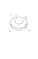
図1は、本発明の第1の実施形態に係るマイクロホン保持構造の外観斜視図である。監視カメラ100は、映像の撮影と記録、音声の検知と記録が可能である。監視カメラ100は筐体を有し、筐体はアッパーケース120とボトムケース150により構成される。アッパーケース120には音を収音するための開口部122が形成されている。アッパーケース120とボトムケース150はそれぞれ、例えば金属ダイキャストやポリカーボネートなどの樹脂成形で作製することができる。アッパーケース120はレンズ保護部材110を備えており、収容される部品を衝撃やゴミから守る役割を担っている。レンズ保護部材110は例えば透明ポリカーボネートなどで形成される。
FIG. 1 is an external perspective view of a microphone holding structure according to a first embodiment of the present invention. The
図2はマイクロホン保持構造の概略構成を示す断面図である。 FIG. 2 is a cross-sectional view showing a schematic configuration of the microphone holding structure.
アッパーケース120とボトムケース150は、爪嵌合でお互いに締結されている。レンズ保護部材110はアッパーケース120に接着剤を用いて固定されている。
The
筐体内部には例えば基板保持部材110、レンズ202と撮像素子204、レンズ駆動装置、センサ基板206、カメラ筐体208などから構成されるカメラ部200が収容されている。筐体内部には、さらに、カメラ部保持部材240、制御基板250、マイク基板270、第1部材としての緩衝部材300が収容される。基板保持部材140は例えばポリカーボネートなどの樹脂成形で作製することができる。
A
カメラ部200はレンズ保護部材110とレンズ202を通じて受光した光を撮像素子204で電気信号に変換する。撮像素子204はセンサ基板206に実装されており、制御基板250へワイヤ230aで電気的に接続され、取得した撮像データを制御基板250に伝送する。
The
制御基板250は電源供給やカメラ制御、ネットワークへの接続など、監視カメラ100全体の制御機能を担っている。制御基板250はボトムケース150にねじなどの固定部材により固定されている。
The
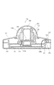
図3はマイクロホン保持構造の詳細構成を示す断面図である。アッパーケース120に形成された開口部122は、筐体内部と外部間に空気や音そして光を通す構造になっている。また開口部底面124は略平面上になっており、緩衝部材300に当接することで筐体内部のノイズが入り込むことを防ぐとともに、外部からの衝撃を緩和している。
FIG. 3 is a cross-sectional view showing a detailed configuration of the microphone holding structure. The opening 122 formed in the
マイク基板270の裏面にはMEMSマイクロホン290が実装されている。そしてMEMSマイクロホン290には収音部292が形成されている。またマイク基板270はワイヤ230bなどで制御基板250に電気的に接続されており、基板保持部材140にねじやテープなどで固定されている。
A MEMS microphone 290 is mounted on the back surface of the
MEMSマイクロホン290は振動膜(ダイアフラム)と固定膜(バックプレート)を半導体基板上に備え小型パッケージ化されている。そして音圧により振動膜が振動し、音圧を電気信号として出力する音響部品である。MEMSマイクロホン290は開口部122と緩衝部材300に形成される音孔330、マイク基板270に形成される穴272を通じて音を取得する。
The MEMS microphone 290 is provided in a small package with a diaphragm (diaphragm) and a fixed film (back plate) on a semiconductor substrate. And it is an acoustic component which vibrates a diaphragm by sound pressure and outputs sound pressure as an electrical signal. The MEMS microphone 290 acquires sound through the
基板保持部材140は略円筒形状の突起部142a、142bを有しており、マイク基板270と緩衝部材300の位置を固定する。
The
ここで緩衝部材300について詳細に説明する。
Here, the
図4は緩衝部材300の断面斜視図である。
FIG. 4 is a cross-sectional perspective view of the
緩衝部材300は略長方形の黒色シリコンゴムなどの光を通さない材質であり、さらに、弾性部材で形成されている。そして筐体内外部からの振動騒音を低減しマイクロホン290のS/Nを向上する役割を担っている。また緩衝部材300は第1の面310と第2の面320を有しており、第1の面310は筐体の開口部底面124と当接するように配置される。第1の面310は開口部122を囲っており、筐体内部からのノイズがMEMSマイクロホン290に入らないよう遮断する役割を担っている。第2の面320はマイク基板270と当接するように配置され、マイク基板270に伝わる振動を減衰させる。緩衝部材300は開口部122の範囲外に位置決め用穴380a、380bを有しており、基板保持部材140の突起部142a、142bが第2の面320側より通ることにより位置が決定される構造になっている。それによりMEMSマイクロホン290の位置と緩衝部材300の配置ずれを防ぐことができ、組立性の向上と適切な収音性能を確保できる。
The
緩衝部材300は音孔330を分断するように配置されるブリッジ部350を有している。ブリッジ部350は収音部292の開口幅よりも大きい幅で形成され、開口部122から入射した光390が収音部292を通過し、MEMSマイクロホン290に直接当たらないよう遮光できる幅を有している。またブリッジ部350は緩衝部材300の基本肉厚より薄く形成されており、マイク穴272とブリッジ部350の間には収音空間360を有している。それによりブリッジ部350が収音部292を塞ぐことなく空気の通り道を確保し、収音性能を確保している。なおブリッジ部350の肉厚は光を通さず、成形性を考慮した肉厚が望ましい。
The
MEMSマイクロホン290を構成している半導体基板に光が当たると、光電効果により電流が発生する。その電流がノイズとなり、MEMSマイクロホン290により収音された音にもノイズが入ってしまうことがある。
When light strikes the semiconductor substrate constituting the
本実施形態1では、開口部122から入った光をブリッジ部350が遮断し、収音部292を通りMEMSマイクロホン290に光が入ることを防ぐ構造になっている。これにより光電効果によるノイズ発生を低減させることが可能になる。仮に開口部122にブリッジ部を設けた場合、MEMSマイクロホン290からの距離が遠いため、ブリッジ部の幅が広く必要になる。また開口部122が分断されることにより、外観品位が低下することが考えられる。よってMEMSマイクロホン290に近い、緩衝部材300にブリッジ部を設けることが望ましい。
In the first embodiment, the
以上により、本発明の第1の実施形態によれば、MEMSマイクロホンでの収音と、内部音ノイズの遮断、衝撃と振動ノイズの低減、そして開口部から入射する光を遮光することが可能となる。その結果、高品質な収音とともに、光電効果に起因するノイズを低減することが可能になる。 As described above, according to the first embodiment of the present invention, it is possible to collect sound by the MEMS microphone, block internal sound noise, reduce impact and vibration noise, and block light incident from the opening. Become. As a result, it is possible to reduce noise caused by the photoelectric effect as well as high-quality sound collection.
なお、上述した本発明の第1の実施形態において、筐体は2部品から構成されているが、3つもしくはそれ以上の部品から構成されていてもよい。 In the above-described first embodiment of the present invention, the housing is composed of two parts, but may be composed of three or more parts.
また、上述した本発明の第1の実施形態において、アッパーケース120とボトムケース150の固定方法は、ねじや接着を用いて固定してもよい。
In the above-described first embodiment of the present invention, the
また、上述した本発明の第1の実施形態において、レンズ保護部材110は球形をしているが、非球面形状や平板形状などでもよい。
In the above-described first embodiment of the present invention, the
また、上述した本発明の第1の実施形態において、レンズ保護部材110の固定方法はねじや超音波溶着、もしくは別部品を用いて固定してもよい。
In the above-described first embodiment of the present invention, the
また、上述した本発明の第1の実施形態において、制御基板250は1つであったが、カメラ制御用と電源管理用などの複数の基板構成であってもよい。
In the above-described first embodiment of the present invention, the number of
また、上述した本発明の第1の実施形態において、制御基板250とセンサ基板206の接続はフレキシブル基板やフラットケーブルを使用して電気的に接続してもよい。
In the first embodiment of the present invention described above, the
また、上述した本発明の第1の実施形態において、マイク基板270はフレキシブル基板などを用いて、ワイヤ230bを用いずに直接制御基板250に接続してもよい。
In the first embodiment of the present invention described above, the
また、上述した本発明の第1の実施形態において、マイク基板270の裏面にMEMSマイクロホン290が実装されていたが、表面に実装されていてもよい。
Further, in the above-described first embodiment of the present invention, the
また、上述した本発明の第1の実施形態において、MEMSマイクロホン290は単数実装されていたが、収音のステレオ化や指向性を調整するために複数実装されていてもよい。
In the first embodiment of the present invention described above, a
また、上述した本発明の第1の実施形態において、緩衝部材300はシリコンゴムで形成されていたが、ジエン系ゴムや熱可塑性エラストマーなど、他の弾性材料で形成してもよい。
In the above-described first embodiment of the present invention, the
また、上述した本発明の第1の実施形態において、緩衝部材300の位置を決めるために位置決め用穴380と基板保持部材110の突起部112を用いたが、緩衝部材300の外形を使用したり、位置決め用の治具を用いたりしてもよい。
In the above-described first embodiment of the present invention, the positioning hole 380 and the protrusion 112 of the
[実施例2]
以下、本発明の第2の実施形態について説明する。監視カメラは屋外で使用することを考慮し、防水防塵構造をとられている場合がある。本発明の第2の実施形態では、上述した本発明の第1の実施形態に係るマイクロホン保持構造と比較して、緩衝部材の形状や防水防塵構造の部品構成が異なる。
[Example 2]
Hereinafter, a second embodiment of the present invention will be described. The surveillance camera may have a waterproof and dustproof structure for outdoor use. The second embodiment of the present invention differs from the microphone holding structure according to the first embodiment of the present invention described above in the shape of the buffer member and the component configuration of the waterproof and dustproof structure.
以下では主に、本発明の第1の実施形態との相違点について重点的に説明し、同一な構成の説明は省略する。 In the following, differences from the first embodiment of the present invention will be mainly described, and description of the same configuration will be omitted.
図1において、アッパーケース120には音声を記録するための音孔と発光穴を兼ねた開口部122が形成されている。アッパーケース120とボトムケース150はパッキン(不図示)を挟み、爪嵌合でお互いに締結されている。それにより筐体内部に水や粉塵が浸入することを防ぐ密閉筐体となっている。レンズ保護部材110は両面テープ(不図示)を挟みアッパーケース120に接着剤を用いて固定されている。パッキンは例えばシリコンやウレタンフォーム材で形成されており、外部からの水や塵の浸入を防ぐ役割を担う。両面テープは例えばアクリル系粘着剤を用いたテープで形成されており、外部からの水や塵の浸入を防ぐ役割を担う。
In FIG. 1, the
図5は本発明の第2の実施形態に係るマイクロホン保持構造の詳細構成を示す断面斜視図である。 FIG. 5 is a cross-sectional perspective view showing the detailed configuration of the microphone holding structure according to the second embodiment of the present invention.
アッパーケース120の内側から開口部122を塞ぐように、通気性をもった防水フィルタ400が配置されている。防水フィルタ400は例えばPTFE(ポリテトラフルオロエチレン)多孔膜で形成されており水や塵の侵入を防ぐ。また防水フィルタ400は防水性能を担保しながらも通気性をもつことでMEMSマイクロホン290の収音性能を低下させることがない。
A
防水フィルタ400の筐体内部側面には透明の支持部材402が貼り付けられている。支持部材402は例えば透明のPETシートなどで形成されている。支持部材402は防水フィルタ400の剛性を高める役割を担い、防水フィルタ400を開口部122に貼り付ける際の作業性が向上する。また、支持部材402は音孔530の上方部に空気を通す空気穴を有している。また、支持部材402は緩衝部材500によって筐体に対して押圧されている。
A
防水フィルタ400は例えば両面テープや接着剤によりアッパーケース120に固定されるが、ねじや爪による嵌合を用いて固定してもよい。
The
マイク基板470の筐体の内部側面にはMEMSマイクロホン290と発光体490が実装されている。またマイク基板470は穴472と発光体穴474が形成されており、基板保持部材410にねじやテープなどで固定されている。発光体490より発せられた光は支持部材402と防水フィルタ400を透過し、開口部122より照射されることで、ユーザーにカメラの電源や録画状態を知らせる。
A
マイク基板470と防水フィルタ400の間に緩衝部材500が配置されており、緩衝部材500はマイク穴472の間に収音空間450を有している。
A
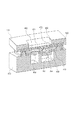
図6は本発明の第2の実施形態に係る緩衝部材の裏面全体斜視図である。 FIG. 6 is an overall rear perspective view of the buffer member according to the second embodiment of the present invention.
緩衝部材500は略長方形のシリコンゴムなどの非透過性弾性部材で形成され、筐体内外部からの振動騒音を低減しMEMSマイクロホン290のS/Nを向上する役割を担っている。また緩衝部材500には音孔530と発光体穴540が形成されており、音孔530には音孔530内に突出する略十字ブリッジ部550が形成されている。そして十字ブリッジ部550とマイク穴472の間に収音空間450を有している。音孔530と発光体穴540を別に設けることにより、発光体490の光がMEMSマイクロホン290に入ることはない。
The
十字ブリッジ部550は収音部292の開口幅よりも大きい幅で形成されている。そして開口部122から入射した光が防水フィルタ400、支持部材402の空気穴を透過し、収音部292よりMEMSマイクロホン290に当たらないよう遮光できる幅を有している。また十字ブリッジ部550は緩衝部材500の基本肉厚より薄く形成されている。
The cross bridge portion 550 is formed with a width larger than the opening width of the
さらに十字ブリッジ部550の根本に補強リブ560を有している。ブリッジ部が十字型になっているため支持点が多くなり、ブリッジ部全体の剛性が高くなっている。さらに補強リブ560により、ブリッジ部根本の変形を抑制できる。収音性能を更に向上させるため音孔530を大きくする場合、ブリッジ部の変形を抑えることで安定した遮光が可能となる。その結果、風雨の強い環境などにカメラを設置した場合でも、光電効果に起因する音ノイズを防ぐことができる。また補強リブ560は十字ブリッジ部550の根本のみを補強することで、収音空間450を確保しMEMSマイクロホン290の収音性能低下を防いでいる。
Further, a reinforcing
防水防塵性能を考えた場合、防水フィルタ400は薄膜シートで形成されているため、外部からの飛来物により破損する恐れがある。その結果、防水防塵性能を満足することができなくなる可能性がある。本実施形態2では、防水フィルタ400に外力が働き、防水フィルタ400が筐体内部方向にたわんだ際、十字ブリッジ部550に当たる構造になっている。十字ブリッジ部550により防水フィルタ400の内側を支えることで、防水フィルタ400が過剰に変形することを抑制し破損を防ぐことができる。その結果、防水防塵性能の信頼性を向上させることができる。
Considering the waterproof and dustproof performance, the
100 監視カメラ
120 アッパーケース
150 ボトムケース
122 開口部
270 マイク基板
290 MEMSマイクロホン
300,500 緩衝部材
330,530 音孔
350,550 ブリッジ部
DESCRIPTION OF
Claims (8)
前記開口部の直下位置に設けられ、前記開口部より収音するMEMSマイクロホンと、
前記開口部を通して前記MEMSマイクロホンへ光が入射することを抑制するために、前記開口部と前記MEMSマイクロホンの間において、前記MEMSマイクロホンの収音部に対応する位置に配置される遮光部材と、
前記開口部を通して前記筐体内へ水が浸入することをするために、前記開口部を塞ぐとともに、通気性を有し、前記遮光部材に接触する防水部材と、を備え、
前記遮光部材は、前記MEMSマイクロホンの収音部の開口幅よりも大きい幅であることを特徴とする、電子機器。 A housing having an opening;
A MEMS microphone provided at a position directly below the opening and collecting sound from the opening;
A light-shielding member disposed between the opening and the MEMS microphone at a position corresponding to the sound collection unit of the MEMS microphone in order to suppress light from entering the MEMS microphone through the opening;
In order to allow water to enter the housing through the opening, the opening is closed, and has a breathability and a waterproof member that contacts the light shielding member ,
The electronic apparatus according to claim 1, wherein the light shielding member has a width larger than an opening width of a sound collection unit of the MEMS microphone .
Priority Applications (3)
| Application Number | Priority Date | Filing Date | Title |
|---|---|---|---|
| JP2017211156A JP6594397B2 (en) | 2017-10-31 | 2017-10-31 | Microphone holding structure |
| US16/162,123 US10534242B2 (en) | 2017-10-31 | 2018-10-16 | Electronic apparatus including holding structure for micro electro mechanical system (MEMS) microphone that reduces sound noise due to photoelectric effect |
| CN201821769422.5U CN208798223U (en) | 2017-10-31 | 2018-10-30 | Electronic device |
Applications Claiming Priority (1)
| Application Number | Priority Date | Filing Date | Title |
|---|---|---|---|
| JP2017211156A JP6594397B2 (en) | 2017-10-31 | 2017-10-31 | Microphone holding structure |
Publications (2)
| Publication Number | Publication Date |
|---|---|
| JP2019083479A JP2019083479A (en) | 2019-05-30 |
| JP6594397B2 true JP6594397B2 (en) | 2019-10-23 |
Family
ID=66212393
Family Applications (1)
| Application Number | Title | Priority Date | Filing Date |
|---|---|---|---|
| JP2017211156A Active JP6594397B2 (en) | 2017-10-31 | 2017-10-31 | Microphone holding structure |
Country Status (3)
| Country | Link |
|---|---|
| US (1) | US10534242B2 (en) |
| JP (1) | JP6594397B2 (en) |
| CN (1) | CN208798223U (en) |
Families Citing this family (7)
| Publication number | Priority date | Publication date | Assignee | Title |
|---|---|---|---|---|
| CN111193847B (en) * | 2018-11-15 | 2023-05-30 | 法可赛阿达斯独资有限公司 | Camera housing for a motor vehicle and method for producing the same |
| KR102633905B1 (en) * | 2019-01-31 | 2024-02-05 | 엘지전자 주식회사 | Refrigerator Capable of Sound Input |
| DE102019206329B4 (en) | 2019-05-03 | 2022-02-03 | Zf Friedrichshafen Ag | Device and system for measuring the volume of noise from a road vehicle in traffic |
| CN110708904B (en) * | 2019-09-25 | 2021-04-27 | 维沃移动通信有限公司 | a mobile terminal |
| CN112492484B (en) * | 2020-12-02 | 2022-08-19 | 潍坊歌尔微电子有限公司 | Miniature microphone dust keeper and MEMS microphone |
| WO2023022418A1 (en) * | 2021-08-18 | 2023-02-23 | (주)에스엠인스트루먼트 | Acoustic camera having waterproof means |
| JP2024177996A (en) * | 2023-06-12 | 2024-12-24 | 株式会社Soken | Vehicle-mounted equipment |
Family Cites Families (9)
| Publication number | Priority date | Publication date | Assignee | Title |
|---|---|---|---|---|
| JP2006186422A (en) | 2004-12-24 | 2006-07-13 | Ricoh Co Ltd | Waterproof electronic equipment |
| JP2009055490A (en) * | 2007-08-29 | 2009-03-12 | Rohm Co Ltd | Microphone apparatus |
| JP2010166286A (en) * | 2009-01-15 | 2010-07-29 | Yamaha Corp | Structure for mounting silicon microphone, and electronic apparatus |
| JP2010171631A (en) * | 2009-01-21 | 2010-08-05 | Yamaha Corp | Silicon microphone |
| JP2012039272A (en) * | 2010-08-05 | 2012-02-23 | Funai Electric Co Ltd | Microphone unit |
| US9560430B2 (en) * | 2012-02-28 | 2017-01-31 | JVC Kenwood Corporation | Waterproof structure and electronic equipment including the same |
| JP6213871B2 (en) * | 2012-12-27 | 2017-10-18 | パナソニックIpマネジメント株式会社 | Waterproof microphone device |
| KR101369464B1 (en) * | 2013-06-27 | 2014-03-06 | 주식회사 비에스이 | MEMS microphone |
| KR102468129B1 (en) * | 2016-06-01 | 2022-11-22 | 삼성전자주식회사 | Electronic device and manufacturing method thereof |
-
2017
- 2017-10-31 JP JP2017211156A patent/JP6594397B2/en active Active
-
2018
- 2018-10-16 US US16/162,123 patent/US10534242B2/en active Active
- 2018-10-30 CN CN201821769422.5U patent/CN208798223U/en active Active
Also Published As
| Publication number | Publication date |
|---|---|
| CN208798223U (en) | 2019-04-26 |
| US10534242B2 (en) | 2020-01-14 |
| US20190127216A1 (en) | 2019-05-02 |
| JP2019083479A (en) | 2019-05-30 |
Similar Documents
| Publication | Publication Date | Title |
|---|---|---|
| JP6594397B2 (en) | Microphone holding structure | |
| US10225634B2 (en) | Electronic apparatus equipped with microphone | |
| US12010485B2 (en) | Submersible speaker system with a compressible spacer | |
| US11579515B2 (en) | Drainage channel for a submersible camera with drainage ports on two surfaces | |
| JP6213871B2 (en) | Waterproof microphone device | |
| US12081939B2 (en) | Submersible microphone system with a compressible spacer | |
| ES2795286T3 (en) | Waterproof case | |
| US20120188690A1 (en) | Waterproof structure for electronic device | |
| US20130271902A1 (en) | Waterproof case | |
| US20120195451A1 (en) | Waterproof structure for electronic device | |
| KR20140135256A (en) | Offset Acoustic Channel For Microphone System | |
| JP6682755B2 (en) | Camera device | |
| JP7130398B2 (en) | microphone unit and electronic equipment | |
| JP2018196109A (en) | Electronics | |
| JP2006352342A (en) | Electronic device with microphone | |
| JP2013157763A (en) | Sound recording device | |
| JP2018026665A (en) | Camera device | |
| JP2005197788A (en) | Electronic camera | |
| JP2013153268A (en) | Electronic apparatus |
Legal Events
| Date | Code | Title | Description |
|---|---|---|---|
| A621 | Written request for application examination |
Free format text: JAPANESE INTERMEDIATE CODE: A621 Effective date: 20180420 |
|
| A521 | Request for written amendment filed |
Free format text: JAPANESE INTERMEDIATE CODE: A523 Effective date: 20180803 |
|
| A131 | Notification of reasons for refusal |
Free format text: JAPANESE INTERMEDIATE CODE: A131 Effective date: 20190604 |
|
| A521 | Request for written amendment filed |
Free format text: JAPANESE INTERMEDIATE CODE: A523 Effective date: 20190731 |
|
| TRDD | Decision of grant or rejection written | ||
| A01 | Written decision to grant a patent or to grant a registration (utility model) |
Free format text: JAPANESE INTERMEDIATE CODE: A01 Effective date: 20190827 |
|
| A61 | First payment of annual fees (during grant procedure) |
Free format text: JAPANESE INTERMEDIATE CODE: A61 Effective date: 20190924 |
|
| R151 | Written notification of patent or utility model registration |
Ref document number: 6594397 Country of ref document: JP Free format text: JAPANESE INTERMEDIATE CODE: R151 |