JP6592379B2 - Solar cell module fixing structure - Google Patents
Solar cell module fixing structure Download PDFInfo
- Publication number
- JP6592379B2 JP6592379B2 JP2016038994A JP2016038994A JP6592379B2 JP 6592379 B2 JP6592379 B2 JP 6592379B2 JP 2016038994 A JP2016038994 A JP 2016038994A JP 2016038994 A JP2016038994 A JP 2016038994A JP 6592379 B2 JP6592379 B2 JP 6592379B2
- Authority
- JP
- Japan
- Prior art keywords
- fixing
- solar cell
- cell module
- crosspiece
- piece
- Prior art date
- Legal status (The legal status is an assumption and is not a legal conclusion. Google has not performed a legal analysis and makes no representation as to the accuracy of the status listed.)
- Active
Links
Images


Classifications
-
- Y—GENERAL TAGGING OF NEW TECHNOLOGICAL DEVELOPMENTS; GENERAL TAGGING OF CROSS-SECTIONAL TECHNOLOGIES SPANNING OVER SEVERAL SECTIONS OF THE IPC; TECHNICAL SUBJECTS COVERED BY FORMER USPC CROSS-REFERENCE ART COLLECTIONS [XRACs] AND DIGESTS
- Y02—TECHNOLOGIES OR APPLICATIONS FOR MITIGATION OR ADAPTATION AGAINST CLIMATE CHANGE
- Y02B—CLIMATE CHANGE MITIGATION TECHNOLOGIES RELATED TO BUILDINGS, e.g. HOUSING, HOUSE APPLIANCES OR RELATED END-USER APPLICATIONS
- Y02B10/00—Integration of renewable energy sources in buildings
- Y02B10/10—Photovoltaic [PV]
-
- Y—GENERAL TAGGING OF NEW TECHNOLOGICAL DEVELOPMENTS; GENERAL TAGGING OF CROSS-SECTIONAL TECHNOLOGIES SPANNING OVER SEVERAL SECTIONS OF THE IPC; TECHNICAL SUBJECTS COVERED BY FORMER USPC CROSS-REFERENCE ART COLLECTIONS [XRACs] AND DIGESTS
- Y02—TECHNOLOGIES OR APPLICATIONS FOR MITIGATION OR ADAPTATION AGAINST CLIMATE CHANGE
- Y02E—REDUCTION OF GREENHOUSE GAS [GHG] EMISSIONS, RELATED TO ENERGY GENERATION, TRANSMISSION OR DISTRIBUTION
- Y02E10/00—Energy generation through renewable energy sources
- Y02E10/50—Photovoltaic [PV] energy
Description
本発明は、太陽電池モジュールを屋根上に固定している太陽電池モジュールの固定構造に関するものである。 The present invention relates to a solar cell module fixing structure in which a solar cell module is fixed on a roof.
屋根上に太陽電池モジュールを固定する固定構造として、屋根上に間隔をあけて取付けられている複数の下固定部材に、屋根の傾斜方向へ延びている状態で傾斜方向に直交する方向へ間隔をあけて複数の桟部材が取付けられており、複数の桟部材を跨ぐように桟部材に載置されている太陽電池モジュールが、上固定部材によって桟部材に固定されている固定構造が提案されている(特許文献1)。 As a fixing structure for fixing the solar cell module on the roof, the plurality of lower fixing members attached at intervals on the roof are spaced in a direction perpendicular to the inclination direction while extending in the inclination direction of the roof. A fixing structure has been proposed in which a plurality of crosspiece members are attached and a solar cell module placed on the crosspiece member so as to straddle the plurality of crosspiece members is fixed to the crosspiece member by an upper fixing member. (Patent Document 1).
特許文献1の技術では、下固定部材が、間に桟部材が挿入される一対の固定片を備えていると共に、桟部材が、両側面において長手方向へ延びている溝を備えている。そして、一対の固定片の間に挿入されている桟部材において、長手方向の端部から溝内に挿入されたナットに、固定片を通したボルトを螺合させることにより、下固定部材に桟部材を取付けている。
In the technique of
しかしながら、特許文献1の技術では、桟部材の長手方向の端部からナットを溝内に挿入しているため、下固定部材の固定片の位置までの長い距離をスライドさせなければならず、手間がかかっていた。
However, in the technique of
これに対して、本願出願人は、桟部材の側面に形成されている溝の開口の上下寸法を大きくすると共に、雌ネジ孔が形成されているスライダ部材を、開口を通して溝内に挿入できるように形成し、溝内に挿入されているスライダ部材の雌ネジ孔に下固定部材を通したボルトを螺合させることにより、下固定部材に桟部材を取付ける技術を提案している(特許文献2)。この特許文献2の技術によれば、桟部材において、下固定部材に近い部位で開口を通してスライダ部材を溝内へ挿入させることができるため、スライドさせる距離が短くなり、手間を低減させられる。また、特許文献2の技術では、スライダ部材のスライド作業を行い易くするために、開口の上下寸法を大きくして作業者の指を挿入し易くしている。
In contrast, the applicant of the present application can increase the vertical dimension of the opening of the groove formed on the side surface of the crosspiece member and insert the slider member in which the female screw hole is formed into the groove through the opening. The technique which attaches a crosspiece member to a lower fixing member by screwing the bolt which let the lower fixing member pass to the female screw hole of the slider member inserted in the groove | channel is proposed (patent document 2). ). According to the technique of
ところで、屋根上に複数の桟部材を取付ける場合、屋根の状態や、下固定部材の取付けられている屋根の部位等によっては、取付けられた複数の桟部材の上面が、不陸な状態(同一面上でない状態)となる場合がある。このような状態で複数の桟部材に跨って太陽電池モジュールを固定すると、太陽電池モジュールが捩れた状態となり、破損する虞がある。そこで、特許文献1及び特許文献2のような技術では、下固定部材の固定片において、ボルトが挿通される固定孔を上下に長い長孔とし、各下固定部材において桟部材の取付け高さを調整できるようにしている。また、固定片に予めビス孔を形成し、桟部材の高さ調整を行った後に、ビス孔を通して桟部材の側面にビスをねじ込むことにより、ボルトが緩んだ時の桟部材の落下を防止している。
By the way, when mounting a plurality of crosspieces on the roof, depending on the state of the roof or the part of the roof to which the lower fixing member is attached, the top surfaces of the plurality of crosspieces attached are in a non-landing state (the same May not be on the surface). If the solar cell module is fixed across the plurality of crosspiece members in such a state, the solar cell module is twisted and may be damaged. Therefore, in the techniques such as
しかしながら、下固定部材に対して桟部材の高さ調整を行った時に、固定片に予め形成されているビス孔の位置が溝の開口と一致した場合、そのビス孔を通して桟部材にビスをねじ込むことができなかった。しかも、特許文献2の技術では、作業者の指を挿入させ易いように、溝の開口の上下寸法を大きくしているため、予め形成されているビス孔と溝の開口とが一致し易いものとなっていた。このようなことから、予め形成されているビス孔と溝の開口とが一致した場合、屋根上において、固定片の別の位置にビス孔をあけて、桟部材にビスをねじ込むようにしており、手間がかかっていた。
However, when the height of the crosspiece member is adjusted with respect to the lower fixing member, if the position of the screw hole formed in the fixed piece coincides with the opening of the groove, the screw is screwed into the crosspiece member through the screw hole. I couldn't. Moreover, in the technique of
そこで、本発明は、上記の実情に鑑み、屋根上での固定作業の手間を低減させることが可能な太陽電池モジュールの固定構造の提供を課題とするものである。 Accordingly, in view of the above circumstances, an object of the present invention is to provide a solar cell module fixing structure capable of reducing the labor of fixing work on the roof.
上記の課題を解決するために、本発明に係る太陽電池モジュールの固定構造は、「屋根上に取付けられている下固定部材と、屋根の傾斜方向に長く延びており太陽電池モジュールが載置されている桟部材と、下用ボルトと協働して前記桟部材を前記下固定部材に締結固定している下用ナット部材と、前記太陽電池モジュールの上面に当接している上固定部材と、上用ボルトと協働して前記太陽電池モジュールを前記桟部材と前記上固定部材とで挟んで締結固定している上用ナット部材とを具備している太陽電池モジュールの固定構造であって、前記下固定部材は、平板状の下ベース片と、該下ベース片から間隔をあけて突出している平板状の一対の下固定片と、夫々の該下固定片を貫通しており、上下に長い下固定孔と、夫々の前記下固定片を貫通しているビス孔とを備えており、前記桟部材は、一対の前記下固定片の間隔よりも短辺が短い長方形の天板部と、該天板部の一方の長辺から下方へ延びている上当接部と、前記天板部の他方の長辺から該上当接部よりも下方へ延びている上接続部と、該上接続部の下辺から前記上当接部の下方まで延びている下接続部と、該下接続部の先端辺から前記上当接部と同一面上に上方へ延出しており、該上当接部との間に一定の間隔の開口部を形成している下当接部と、前記天板部を貫通しており、該天板部の長手方向へ延びている挿通部とを備え、前記上当接部及び前記下当接部が、一方の前記下固定片の内側面に当接しており、前記下用ナット部材は、固定方向が前記開口部の間隔よりも長く、前記天板部と前記下接続部との間隔よりも短い平板状の本体部と、該本体部を貫通している雌ネジ孔とを備え、前記開口部を通して前記桟部材の内部に挿入されていると共に、前記本体部の前記固定方向の一方の端部側が前記上当接部の内側面に他方の端部側が前記下当接部の内側面に夫々当接しており、前記下用ボルトは、一対の前記下固定片のうち、前記上当接部及び前記下当接部と当接している前記下固定片の前記下固定孔及び前記開口部を貫通した雄ネジ部が、前記雌ネジ孔に螺合されて締付けられている」ものである。 In order to solve the above-described problems, the solar cell module fixing structure according to the present invention includes a “lower fixing member attached on the roof and a long extension in the inclination direction of the roof, on which the solar cell module is placed. A crosspiece member, a lower nut member that fastens and fixes the crosspiece member to the lower fixing member in cooperation with a lower bolt, an upper fixing member that is in contact with the upper surface of the solar cell module, A solar cell module fixing structure comprising an upper nut member that clamps and fixes the solar cell module between the crosspiece member and the upper fixing member in cooperation with an upper bolt, The lower fixing member passes through the lower fixing piece, a flat plate-like lower base piece, a pair of flat lower fixing pieces protruding from the lower base piece at intervals, and vertically. Long lower fixing holes and respective lower fixing pieces The crosspiece member includes a rectangular top plate portion whose shorter side is shorter than the interval between the pair of lower fixing pieces, and downward from one long side of the top plate portion. An upper contact portion that extends, an upper connection portion that extends downward from the other long side of the top plate portion, and a lower side of the upper connection portion that extends to a position below the upper contact portion. A lower connecting portion and a lower connecting portion that extends upward from the tip side of the lower connecting portion on the same plane as the upper abutting portion, and that has openings with a constant interval between the lower abutting portion and the upper abutting portion. A contact portion and an insertion portion that penetrates the top plate portion and extends in the longitudinal direction of the top plate portion, and the upper contact portion and the lower contact portion are one of the lower fixed pieces. The lower nut member has a fixing direction longer than the interval between the openings, and is longer than the interval between the top plate portion and the lower connection portion. A flat plate-like main body portion and a female screw hole penetrating the main body portion, and inserted into the crosspiece member through the opening, and one end of the main body portion in the fixing direction The part side is in contact with the inner side surface of the upper contact part, and the other end side is in contact with the inner side surface of the lower contact part, and the lower bolt is the upper contact part of the pair of lower fixing pieces and The male screw part that penetrates the lower fixing hole and the opening of the lower fixing piece that is in contact with the lower abutting part is screwed into the female screw hole and tightened. "
ここで、「下固定部材」としては、「屋根材の上面に直接取付けられるもの」、「屋根材の上面に取付けられている取付部材に取付けられるもの」、「基端側が屋根材を取付けている屋根構造材に取付けられており、先端側が屋根材よりも上方に突出している取付部材に取付けられるもの」、を例示することができる。 Here, as "the lower fixing member", "the one that can be directly attached to the top surface of the roofing material", "the one that can be attached to the mounting member that is attached to the top surface of the roofing material", It is attached to a roof structure material that is attached to an attachment member that protrudes upward from the roof material ”.
上用ボルトと上用ナット部材との関係としては、「上用ナット部材が、桟部材の天板部の下面に当接していると共に、上用ボルトの雄ネジ部が、上固定部材及び天板部の挿通部を通して上用ナット部材に螺合しているもの」、「上用ボルトの雄ネジ部が、桟部材の天板部の挿通部を下から貫通し上固定部材を通って上方へ延出していると共に、上用ナット部材が上用ボルトの雄ネジ部の上端から螺合されているもの」、を例示することができる。 The relationship between the upper bolt and the upper nut member is as follows: “The upper nut member is in contact with the lower surface of the top plate portion of the crosspiece member and the male screw portion of the upper bolt is connected to the upper fixing member and the top nut member. "The screw threaded into the upper nut member through the insertion part of the plate part", "The male screw part of the upper bolt passes through the insertion part of the top plate part of the crosspiece member from below and passes through the upper fixing member. And the upper nut member is screwed from the upper end of the male screw portion of the upper bolt ”.
天板部を貫通している挿通部は、桟部材の長手方向に長い長孔としても良いし、桟部材において天板部との間に間隔をあけて上当接部と上接続部とを繋いでいる連結部が備えられている場合では桟部材の全長に渡って延びているスリットとしても良い。 The insertion portion penetrating the top plate portion may be a long hole extending in the longitudinal direction of the crosspiece member, or the upper contact portion and the upper connection portion are connected to the crosspiece member with a space between the top plate portion. In the case where the connecting portion is provided, it may be a slit extending over the entire length of the crosspiece member.
本構成の太陽電池モジュールの固定構造は、例えば、以下のように構築することができる。まず、複数の下固定部材を、一対の下固定片を屋根の傾斜方向と平行とした状態で、傾斜方向及び傾斜方向と直角方向(以下では、単に横方向と称する)に夫々間隔をあけて屋根上に取付ける。続いて、傾斜方向に並んでいる複数の下固定部材の一対の下固定片の間に、上から桟部材を挿入する。そして、下用ナット部材を、下固定片の近傍の部位において開口部を通して桟部材の内部に挿入し、その固定方向を上下に向けて本体部の片面を上当接部の内側面と下当接部の内側面とに当接させる。続いて、下用ナット部材を下固定片の方向へスライドさせて、雌ネジ孔を下固定片の下固定孔と一致させる。この状態で、下固定片の下固定孔及び開口部を通して雌ネジ孔に下用ボルトの雄ネジ部を螺合して締付ける。 The fixing structure of the solar cell module of this configuration can be constructed as follows, for example. First, a plurality of lower fixing members are spaced apart in the inclined direction and in a direction perpendicular to the inclined direction (hereinafter simply referred to as the lateral direction) with the pair of lower fixed pieces parallel to the inclined direction of the roof. Install on the roof. Subsequently, the crosspiece member is inserted from above between the pair of lower fixing pieces of the plurality of lower fixing members arranged in the inclined direction. Then, the lower nut member is inserted into the crosspiece member through the opening at the portion in the vicinity of the lower fixed piece, and one side of the main body portion is brought into lower contact with the inner surface of the upper contact portion with the fixing direction thereof being directed upward and downward It abuts on the inner surface of the part. Subsequently, the lower nut member is slid in the direction of the lower fixing piece so that the female screw hole is aligned with the lower fixing hole of the lower fixing piece. In this state, the male screw portion of the lower bolt is screwed and tightened into the female screw hole through the lower fixing hole and the opening of the lower fixing piece.
これにより、桟部材の上当接部と下当接部が一対のうち一方の下固定片の内側面に当接すると共に、下用ナット部材の本体部の固定方向の一方の端部側が上当接部の内側面に他方の端部側が下当接部の内側面に夫々当接し、下固定片と桟部材の上当接部及び下当接部とが、下用ナット部材と下用ボルトの頭部との間に挟まれた状態となり、下用固定部材に桟部材が固定される。 Accordingly, the upper contact portion and the lower contact portion of the crosspiece member are in contact with the inner surface of one lower fixing piece of the pair, and one end side in the fixing direction of the main body portion of the lower nut member is the upper contact portion. The other end side is in contact with the inner surface of the lower contact portion, and the lower fixing piece and the upper contact portion and lower contact portion of the cross member are the lower nut member and the head of the lower bolt. And the crosspiece member is fixed to the lower fixing member.
下用固定部材に桟部材を固定する際に、屋根上において複数の桟部材の上面が、同一面上となるように、上下に長い下固定孔の範囲内で、各下用固定部材に対する桟部材の高さを調整する。そして、桟部材の高さを調整したら、下用ボルトを強く締付けた後に、下用固定部材の反対側の固定片のビス孔を通して桟部材の上接続部にビスをねじ込む。これにより、下用固定部材に対する桟部材の落下と傾斜方向への移動とが防止される。 When fixing the crosspiece member to the lower fixing member, the crosspiece with respect to each lower fixing member is within the range of the lower fixing holes that are vertically long so that the upper surfaces of the plurality of crosspiece members are on the same surface on the roof. Adjust the height of the member. Then, after adjusting the height of the crosspiece member, after tightening the lower bolt strongly, the screw is screwed into the upper connection portion of the crosspiece member through the screw hole of the fixing piece opposite to the lower fixing member. Thereby, the crosspiece member is prevented from dropping and moving in the inclined direction with respect to the lower fixing member.
上記のように複数の桟部材を屋根上に固定したら、複数(例えば、二つ)の桟部材に跨るように太陽電池モジュールを載置し、太陽電池モジュールの辺縁において桟部材と交差している部位の上面に、上固定部材を当接させる。そして、桟部材の挿通部及び上固定部材を挿通させた上用ボルトの雄ネジ部に上用ナット部材を螺合して締付けることで、上固定部材と桟部材とで太陽電池モジュールを挟んで締結固定する。この際に、天板部よりも下方に位置される上用ナット部材又は上用ボルトを、開口部を通して桟部材の内部に挿入することができる。このようにして、屋根上に固定されている太陽電池モジュールの固定構造を構築することができる。 When a plurality of crosspiece members are fixed on the roof as described above, the solar cell module is placed so as to straddle a plurality of (for example, two) crosspiece members, and crosses the crosspiece members at the edge of the solar cell module. The upper fixing member is brought into contact with the upper surface of the existing portion. Then, the upper nut member is screwed and tightened to the male screw portion of the upper bolt through which the insertion portion of the crosspiece member and the upper fixing member are inserted, so that the solar cell module is sandwiched between the upper fixing member and the crosspiece member. Fasten and fix. At this time, the upper nut member or the upper bolt positioned below the top plate portion can be inserted into the crosspiece member through the opening. In this way, a structure for fixing the solar cell module fixed on the roof can be constructed.
このように、本構成によれば、桟部材の上接続部には、開口部が形成されていないため、桟部材をどのような高さに調整しても、下固定片に形成されているビス孔を通して上接続部にビスをねじ込むことができる。これにより、桟部材の落下を防止するためのビス孔を、予め下固定片に形成しておくことができ、屋根上でのビス孔の穿設作業をなくすことができる。 Thus, according to this structure, since the opening is not formed in the upper connection part of the crosspiece member, it is formed in the lower fixed piece regardless of the height of the crosspiece member. Screws can be screwed into the upper connecting portion through the screw holes. Thereby, the screw hole for preventing the crosspiece member from falling can be formed in the lower fixed piece in advance, and the work of drilling the screw hole on the roof can be eliminated.
また、桟部材の両側面のうち開口部が設けられた側面では、ビス孔を通してビスをねじ込む必要がないため、開口部の上下寸法をより大きくして、作業者の指を挿入し易いものとすることができる。これにより、作業者が下用ナット部材を摘んだ状態で、開口部から桟部材の内部へ挿入したり、内部に挿入した下用ナット部材を上当接部の内面と下当接部の内面に当接させたり、内部に挿入した下用ナット部材を下固定片側へスライドさせたりする作業を容易に行うことができる。 Also, it is not necessary to screw the screw through the screw hole on the side surface where the opening is provided on both side surfaces of the crosspiece member, so that the vertical dimension of the opening is made larger and the operator's finger can be easily inserted. can do. As a result, with the operator holding the lower nut member, it can be inserted into the crosspiece member from the opening, or the lower nut member inserted inside can be attached to the inner surface of the upper contact portion and the inner surface of the lower contact portion. It is possible to easily perform the operation of abutting or sliding the lower nut member inserted into the lower fixed piece side.
このように、太陽電池モジュールの屋根上での固定作業の手間を低減させることができる。 Thus, the trouble of fixing work on the roof of a solar cell module can be reduced.
本構成の太陽電池モジュールの固定構造は、上記の構成に加えて、「前記桟部材は、前記上当接部及び前記下当接部の夫々の内側面から突出しており、長手方向へ延びている一対の開口突条を、更に備えており、前記下用ナット部材は、前記本体部に、一対の前記開口突条が挿入される溝部が形成されている」ものとすることができる。 The fixing structure of the solar cell module of this configuration is in addition to the above-described configuration. “The crosspiece member protrudes from the inner surface of each of the upper contact portion and the lower contact portion and extends in the longitudinal direction. A pair of opening ridges is further provided, and the lower nut member is formed with a groove portion into which the pair of opening ridges are inserted in the main body portion.
本構成によれば、下用ナット部材の二つの溝部に、桟部材の一対の開口突条が夫々挿入されることで、桟部材の変形により、開口部が広がったり狭くなったりすることを、下用ナット部材によって規制できる。これにより、桟部材の変形を抑制することができるため、太陽電池モジュールの屋根上への固定構造の安定性を高めることができる。 According to this configuration, the pair of opening protrusions of the crosspiece member are respectively inserted into the two groove portions of the lower nut member, so that the opening portion is expanded or narrowed by deformation of the crosspiece member. It can be regulated by the lower nut member. Thereby, since a deformation | transformation of a crosspiece member can be suppressed, stability of the fixing structure to the roof of a solar cell module can be improved.
本構成の太陽電池モジュールの固定構造は、上記の構成に加えて、「前記上固定部材は、平板状の上ベース片と、該上ベース片の一対の辺から夫々延出しており、前記太陽電池モジュールの上面と当接している一対の上固定片と、前記上ベース片を貫通しており、前記上用ボルトの雄ネジ部が挿通されている上固定孔と、前記上ベース片の前記一対の辺の一方から下方へ延出しており、下端が前記桟部材に当接している脚片とを備えている」ものとすることができる。 In addition to the above-described configuration, the solar cell module fixing structure according to the present configuration is “the upper fixing member extends from a flat upper base piece and a pair of sides of the upper base piece. A pair of upper fixing pieces that are in contact with the upper surface of the battery module; an upper fixing hole that passes through the upper base piece and through which a male screw portion of the upper bolt is inserted; and the upper base piece A leg piece extending downward from one of the pair of sides and having a lower end in contact with the crosspiece member ”.
「上固定部材」としては、「上ベース片の一対の辺から夫々上方へ延出している一対の立片を備え、一対の立片の上端から上固定片が夫々延出しているもの」、「上ベース片の一対の辺から一対の上固定片が夫々直接延出しているもの」、を例示することができる。 As the “upper fixing member”, “a pair of standing pieces extending upward from a pair of sides of the upper base piece, respectively, and the upper fixing pieces extending from the upper ends of the pair of standing pieces”, “A pair of upper fixing pieces directly extending from a pair of sides of the upper base piece” can be exemplified.
ところで、特許文献1の技術では、太陽電池モジュールの上面に当接している上固定部材が、桟部材から離れている。そのため、屋根の傾斜方向へ並んでいる二つの太陽電池モジュールの間に位置している上固定部材では、夫々の太陽電池モジュールを位置決めした後に、夫々の上面に上固定部材を当接させて、上固定部材を貫通している上用ボルトにナットを締付けることにより、二つの太陽電池モジュールを同時に固定している。従って、作業者は、太陽電池モジュールを跨ぐような姿勢でナットを締付けることとなるため、太陽電池モジュールを傷つけないように細心の注意を払いながら作業する必要があり、手間がかかっていた。
By the way, in the technique of
これに対して、本構成では、上固定部材に、桟部材と当接する脚片を備えていることから、一対のうち一方の上固定片を太陽電池モジュールに当接させると共に、脚片の下端を桟部材に当接させた状態で、上用ボルトと上用ナット部材とで締付けると、上固定部材が倒れることなく太陽電池モジュールを桟部材に固定することができる。そして、一方の上固定片で太陽電池モジュールを桟部材に固定した後に、他方の上固定片と桟部材との間に、次の太陽電池モジュールを桟部材に対して斜めにした状態で、その辺縁を挿入してから、反対側の辺縁を桟部材に載置しつつ、先に固定されている太陽電池モジュール側へスライドさせることにより、一つの上固定部材において両側に太陽電池モジュールを固定することができる。 On the other hand, in this structure, since the upper fixing member includes the leg piece that comes into contact with the crosspiece member, one upper fixing piece of the pair is brought into contact with the solar cell module, and the lower end of the leg piece. If the upper bolt and the upper nut member are tightened in a state where the upper plate is in contact with the crosspiece member, the solar cell module can be fixed to the crosspiece member without falling down. Then, after fixing the solar cell module to the crosspiece member with one upper fixing piece, the next solar cell module is inclined with respect to the crosspiece member between the other upper fixing piece and the crosspiece member. After inserting the edge, slide the solar battery module on both sides in one upper fixing member by sliding it to the solar cell module side fixed first while placing the opposite edge on the crosspiece member Can be fixed.
従って、屋根の傾斜方向に複数の太陽電池モジュールを固定する際に、屋根の傾斜方向に対して、一方側から順番に太陽電池モジュールを固定することができるため、作業者が太陽電池モジュールを跨ぐように姿勢をとる必要がなく、楽な姿勢で作業を行うことができる。また、桟部材に固定する前に複数の太陽電池モジュールを並べる必要がなく、屋根上での手間を低減させることができる。 Accordingly, when fixing a plurality of solar cell modules in the roof inclination direction, the solar cell modules can be fixed in order from one side with respect to the roof inclination direction, so that the operator straddles the solar cell modules. Thus, it is not necessary to take a posture, and the work can be performed in an easy posture. Moreover, it is not necessary to arrange a plurality of solar cell modules before fixing to the crosspiece member, and labor on the roof can be reduced.
以上のように、本発明の効果として、屋根上での固定作業の手間を低減させることが可能な太陽電池モジュールの固定構造を提供することができる。 As described above, as an effect of the present invention, it is possible to provide a solar cell module fixing structure capable of reducing the labor of fixing work on the roof.
本発明の一実施形態である太陽電池モジュール2の固定構造1(以下、単に固定構造1と称す)について、図1乃至図17を参照して詳細に説明する。
A fixing structure 1 (hereinafter simply referred to as a fixing structure 1) of a
本実施形態の固定構造1は、屋根上に取付けられている下固定部材10と、屋根の傾斜方向に長く延びており太陽電池モジュール2が載置されている桟部材20と、下用ボルト4と協働して桟部材20を下固定部材10に締結固定している下用ナット部材30と、太陽電池モジュール2の上面に当接している上固定部材40と、上用ボルト5と協働して太陽電池モジュール2を桟部材20と上固定部材40とで挟んで締結固定している上用ナット部材50と、を備えている。本実施形態では、下用ボルト4及び上用ボルト5が、一般的なボルトであり、平座金とバネ座金が予め挿入されている。
The fixing
また、固定構造1は、桟部材20と太陽電池モジュール2との間に挟まれており、太陽電池モジュール2と桟部材20との間や、上固定部材40を間にして両側に固定されている二つの太陽電池モジュール2の間を、電気的に接続しているアース金具60と、最も軒側の太陽電池モジュール2の軒側の辺縁に沿って延びるように複数の桟部材20に跨って取付けられている軒カバー70と、を備えている。
The fixing
下固定部材10は、平板状の下ベース片11と、下ベース片11から間隔をあけて上方へ突出している平板状の一対の下固定片12と、夫々の下固定片12を貫通しており上下に長い下固定孔13と、下固定孔13とは異なる位置で夫々の下固定片12を貫通している複数のビス孔14と、一対の下固定片12の夫々の内側側面における下固定孔13よりも下側の部位から突出している突出片15と、下ベース片11を貫通している下取付孔16と、を備えている(図2及び図3を参照)。
The
一対の下固定片12は、下ベース片11の平行な二辺から突出している。下固定孔13及び下取付孔16は、下ベース片11及び下固定片12における、上下方向と直交し下固定片12と平行な方向の中央に形成されている。ビス孔14は、夫々の下固定片12において、下固定孔13よりも高い位置で、下固定孔13の両側に一つずつ対称に形成されている。
The pair of
下固定部材10は、単一の断面形状で延びているアルミニウム合金の押出型材を、50mm〜100mmの長さで切断した後に、下固定孔13、ビス孔14、及び下取付孔16を穿設したものである。
The
桟部材20は、図6に示すように、平板状で長方形の天板部21と、天板部21の一方の長辺から下方へ延びている上当接部22と、天板部21の他方の長辺から上当接部22よりも下方まで延びている上接続部23と、上接続部23の下辺から上当接部22の下方まで延びている下接続部24と、下接続部24の先端辺から上当接部22と同一面上で上方へ延出していると共に、上当接部22との間に一定の間隔の開口部20aを形成している下当接部25と、天板部21を貫通しおり、天板部21の長手方向へ延びている複数の挿通部26と、を備えている。
As shown in FIG. 6, the
本実施形態の桟部材20では、天板部21は、短辺が一対の下固定片12の間隔よりも短い。上接続部23と下接続部24との境は明瞭ではなく湾曲している。挿通部26は、太陽電池モジュール2の短辺の長さに対応している間隔で、桟部材20の長手方向に複数形成されている。桟部材20は、天板部21の上面から下接続部24の下面までの距離が、下固定部材10において、下固定片12の上端から突出片15の上面までの距離よりも長く形成されている。
In the
また、桟部材20は、上接続部23を貫通していると共に長手方向に長いボルト挿通孔23aと、上当接部22及び下当接部25の夫々の内側面から突出している一対の開口突条27と、天板部21の下面から突出している一対の天板突条28と、を備えている。ボルト挿通孔23aは、上接続部23において、一対の開口突条27の間の中央の高さと同じ高さに形成されている。また、ボルト挿通孔23aは、桟部材20の長手方向の一方の端部に近い部位に形成されている。上当接部22側の開口突条27は、上当接部22の下端よりも上方の位置から突出している。下当接部25側の開口突条27は、下当接部25の上端から突出している。一対の天板突条28は、挿通部26に対して対称の位置から突出している。
Further, the
桟部材20は、単一の断面形状で延びているアルミニウム合金の押出型材に対して、挿通部26及びボルト挿通孔23aを穿設したものである。本実施形態では、桟部材20の開口部20aの上下方向の寸法が、作業者の指が入るように、30mm〜50mmに形成されている。
The
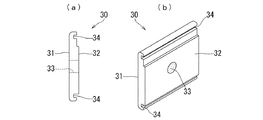
下用ナット部材30は、図7に示すように、平板状の本体部31と、本体部31の一方の側面から膨出している膨出部32と、膨出部32及び本体部31を貫通している雌ネジ孔33と、膨出部32の両外側に夫々形成されており平行に延びている一対の溝部34と、を備えている。
As shown in FIG. 7, the
本体部31は、一対の溝部34と直交する方向の長さが、桟部材20における一対の開口突条27同士の間隔よりも長く、天板部21と下接続部24との間の間隔よりも短い。膨出部32は、一対の溝部34と直交する方向の長さが、桟部材20の開口部20aの上下寸法よりも若干短く、本体部31から突出している長さが上当接部22及び下当接部25の厚さよりも短い。一対の溝部34は、桟部材20の一対の開口突条27の間隔と同じ間隔で、一対の開口突条27が挿入されるように形成されている。一対の溝部34は、上当接部22側の開口突条27と対応している側が、膨出部32の端辺から離れており、下当接部25側の開口突条27と対応している側が、膨出部32の端辺と連続している。
The length of the
下用ナット部材30は、単一の断面形状で延びており、下固定部材10の下固定片12と同じ長さ(幅)に形成されている。雌ネジ孔33は、溝部34が延びている方向の中央で、且つ、一対の溝部34の間の中央に形成されている。下用ナット部材30は、アルミニウム合金やステンレス鋼等の金属によって形成されている。
The
上固定部材40は、図8に示すように、四角形で平板状の上ベース片41と、上ベース片41の平行に延びている二辺から夫々上方へ延出している一対の立片42と、一対の立片42の上端から夫々外側へ延出している一対の上固定片43と、上ベース片41を貫通している上固定孔44と、一対の立片42の一方から下方へ延出している脚片45と、他方の立片42から脚片45よりも短く下方へ延出しているガイド片46と、を備えている。
As shown in FIG. 8, the upper fixing
一対の立片42は、互いに対面している側面から係止突起42aが夫々突出している。係止突起42aは、屋根上に固定されている太陽電池モジュール2同士の間の隙間を塞ぐための図示しない隙間カバーを取付けるためのものである。
As for a pair of standing
一対の上固定片43のうち脚片45と同じ側を第一上固定片43aとし、反対側を第二上固定片43bとする。第一上固定片43aは、先端側へ向かうに従って低くなるように傾斜した後に、先端付近で屈曲して、先端へ向かうほど高くなるように傾斜している。第二上固定片43bは、上ベース片41と平行に延びている。ガイド片46は、下端が脚片45側へ膨らんでいる。
Of the pair of
上固定部材40は、第一上固定片43aの下面から脚片45の下端までの距離が、太陽電池モジュール2の上下寸法(厚さ)より若干短い。この上固定部材40は、単一の断面形状で延びているアルミニウム合金の押出型材を、50mm〜100mmの長さで切断した後に、上固定孔44を穿設したものである。上固定孔44は、押出方向の中央に形成されている。
In the upper fixing
上用ナット部材50は、図9に示すように、四角形で平板状の本体部51と、本体部51を貫通している雌ネジ孔52と、本体部51の上面において平行に延びている一対の溝部53と、を備えている。雌ネジ孔52は、本体部51の中央に形成されている。一対の溝部53は、桟部材20の一対の天板突条28と同じ間隔で、天板突条28が挿入されるように形成されている。上用ナット部材50は、アルミニウム合金やステンレス鋼等の金属によって形成されている。
As shown in FIG. 9, the
アース金具60は、図10に示すように、長方形で平板状の本体部61と、本体部61の中央を貫通している挿通孔62と、本体部61の上面及び下面から突出しており先端が尖っている複数の突刺片63と、本体部61の一対の長辺から下方へ延出している一対のフランジ部64と、を備えている。本体部61は、長辺が上固定部材40の一対の上固定片43の先端間の距離よりも長く形成されていると共に、短辺が、桟部材20の天板部21の幅よりも若干長く形成されている。複数の突刺片63は、本体部61において、長手方向の端部付近に備えられている。アース金具60は、薄いステンレス鋼板をプレス成形したものである。
As shown in FIG. 10, the ground metal fitting 60 protrudes from a rectangular and
軒カバー70は、長方形で平板状の底壁片71と、底壁片71の一方の長辺から上方へ延出している立壁片72と、立壁片72の上辺から底壁片71の上方へ底壁片71よりも短く平行に延出している上壁片73と、上壁片73の立壁片72とは反対側の長辺から底壁片71の他方の長辺まで斜めに延出している傾斜壁片74と、傾斜壁片74の下端から傾斜壁片74と同一面上に下方へ延出している延長壁片75と、立壁片72から底壁片71とは反対側へ突出している係止片76と、を備えている(図4を参照)。
The eaves cover 70 has a rectangular and flat
軒カバー70は、底壁片71の底面から上壁片73の上面までの距離が、太陽電池モジュール2の厚さと同一である。延長壁片75は、傾斜壁片74よりも長く下方へ延びている。係止片76は、立壁片72から直角に延びた後に上方へ延び、更に上端が立壁片72側へ短く屈曲している。係止片76は、立壁片72との間に、上固定部材40におけるガイド片46の下端を収容する空間を形成するものである。軒カバー70は、単一の断面形状で延びているアルミニウム合金の押出型材を、太陽電池モジュール2の長辺と同じ長さに切断したものである。
In the eaves cover 70, the distance from the bottom surface of the
次に、屋根上に太陽電池モジュール2を固定することにより、本実施形態の固定構造1を構築する方法を、主に図11乃至図17等を参照して説明する。まず、複数の下固定部材10を、一対の下固定片12が屋根の傾斜方向と平行となるように屋根材3上に取付ける。本実施形態では、屋根の傾斜方向及び横方向に間隔をあけて屋根材3に取付部材6が取付けられており、その取付部材6から上方へ突出している雄ネジ部6aを、下取付孔16に下から挿通し、ナット6bを締付けることにより、下固定部材10を屋根材3上に取付ける(図3を参照)。その後、傾斜方向に並んでいる複数の下固定部材10の一対の下固定片12の間に、上から桟部材20を挿入する。この際に、桟部材20において、ボルト挿通孔23aに近い端部を、屋根の軒側へ向ける。
Next, a method of constructing the fixing
そして、最も軒側に位置している下固定部材10から、桟部材20の固定を始める。まず、桟部材20を屋根の傾斜方向へ適宜移動させて、ボルト挿通孔23aを、最も軒側の下固定部材10の下固定孔13と重なった状態とする。
Then, the fixing of the
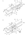
続いて、下固定部材10の近傍の位置において、下用ナット部材30を、桟部材20の上当接部22と下当接部25の間の開口部20aを通して内部に挿入する。この際に、下用ナット部材30を、膨出部32を上方へ向けると共に、膨出部32から離れている溝部34が上側となるように斜めにした状態で、桟部材20の内部に挿入する(図11(a)及び図12を参照)。
Subsequently, at a position near the lower fixing
そして、桟部材20の内部において、斜めになっている膨出部32が、垂直となるように、下用ナット部材30を立てると共に、上当接部22及び下当接部25側へ移動させて、膨出部32を上当接部22と下当接部25の間に挿入させると共に、一対の溝部34内に一対の開口突条27を夫々挿入させる(図11(b)、図11(c)、及び図13(c)を参照)。
Then, the
この状態で、下用ナット部材30を下固定部材10側へスライドさせて、雌ネジ孔33を下固定孔13に臨ませる。この際に、下固定片12と下用ナット部材30との夫々の屋根の傾斜方向の長さ(幅)が、同じであるため、下用ナット部材30の端辺が、下固定片12の端辺と一致するまでスライドさせるだけで、簡単に雌ネジ孔33を下固定孔13に臨ませることができる(図13(d)を参照)。
In this state, the
そして、下固定孔13を通して雌ネジ孔33に、下用ボルト4の雄ネジ部4aを螺合させて軽く締付ける。これにより、下用ナット部材30と下用ボルト4の頭部との間に下固定片12と上当接部22及び下当接部25とが挟まれた状態となり、桟部材20が下固定部材10に仮固定される。最も軒側の下固定部材10では、下用ボルト4として、雄ネジ部4aの長さが、一対の下固定片12の間隔よりも長いものを用いる。この長い下用ボルト4をねじ込むことにより、雄ネジ部4aの先端が、ボルト挿通孔23a及び下固定孔13を貫通して、反対側の下固定片12から外方へ突出した状態となる(図3(a)を参照)。これにより、仮に下用ボルト4が緩んでも、ボルト挿通孔23aと下固定孔13とを貫通している雄ネジ部4aにより、桟部材20の軒方向への移動を防止することができる。
Then, the
最も軒側の下固定部材10において、下用ナット部材30及び下用ボルト4により桟部材20を仮固定したら、これより棟側にある下固定部材10においても、上記と同様に、下用ナット部材30及び下用ボルト4を用いて桟部材20を仮固定する。この際に用いる下用ボルト4は、雄ネジ部4aが下用ナット部材30を貫通する程度の長さのものを用いる(図3(b)を参照)。
When the
そして、各下固定部材10では、図14に示すように、下固定孔13の上下の長さの範囲内で、桟部材20が固定される高さを調整することができる。そこで、複数の桟部材20の上面が同一平面上となるように、各下固定部材10に仮固定した桟部材20の高さを調整してから、下用ボルト4を強く締付けて、下固定部材10に桟部材20を締結固定する。その後、一対の下固定片12のうち桟部材20の上当接部22及び下当接部25が当接している下固定片12とは反対側の下固定片12のビス孔14を通して上接続部23にビス7をねじ込む。このビス7によって、下固定部材10に対して桟部材20の上下方向と傾斜方向の移動を規制することができる。
And in each lower fixing
次に、軒カバー70に上固定部材40を組付ける。図15に示すように、軒カバー70の長手方向の端部から、上固定部材40のガイド片46の下端を、軒カバー70の立壁片72と係止片76との間の空間に挿入する。軒カバー70に上固定部材40を組付けた状態では、第二上固定片43bが上壁片73に当接している。軒カバー70には、跨る桟部材20と同じ数(ここでは二つ)の上固定部材40を組付ける。
Next, the upper fixing
上固定部材40を組付けた軒カバー70を、傾斜壁片74を軒側へ向けた状態で、延長壁片75が桟部材20よりも軒側となるように底壁片71を桟部材20(天板部21)に載置する。この際に、軒カバー70を、跨って載置される複数の桟部材20に対して、屋根の横方向に均等な状態となるように載置する。そして、軒カバー70に組付けられている上固定部材40を、屋根の横方向へスライドさせて、桟部材20の上方に位置させる。
With the eaves cover 70 assembled with the upper fixing
続いて、上用ナット部材50を、溝部53が形成されている面を上方へ向けた状態で、桟部材20の開口部20aから内部に挿入し、一対の溝部53内に一対の天板突条28を夫々挿入させて、上面を天板部21の下面に当接させる。そして、上用ナット部材50を桟部材20の長手方向(屋根の傾斜方向)へスライドさせて、雌ネジ孔52、挿通部26、及び上固定孔44が上下に連通した状態とする。この状態で、上用ボルト5の雄ネジ部5aを、上方から上固定孔44及び挿通部26を通して雌ネジ孔52に螺合させて締付ける。また、軒カバー70の長手方向両端に、平板状の端部カバー77をビス8によって取付ける(図1及び図5を参照)。これにより、桟部材20に軒カバー70が固定されている状態となる。
Subsequently, the
次に、軒カバー70を固定している上固定部材40の第一上固定片43aと桟部材20との間に、棟側から太陽電池モジュール2の長辺側の辺縁を挿入する。詳しくは、太陽電池モジュール2を、軒側の辺縁を桟部材20に載置すると共に、棟側の辺縁を桟部材20よりも上方へ位置させて、桟部材20に対して斜めにした状態とする。そして、軒側の辺縁を第一上固定片43aと桟部材20との間に挿入してから、反対側の軒側の辺縁を桟部材20に載置しつつ、軒側へスライドさせる(図17(a)及び(b)を参照)。これにより、太陽電池モジュール2の軒側の辺縁の上面が第一上固定片43aにより桟部材20へ押圧され、太陽電池モジュール2の軒側の辺縁が桟部材20と上固定部材40とで挟まれて固定された状態となる。この際に、第一上固定片43aでは、先端が斜め上方へ折れ曲がっているため、太陽電池モジュール2の辺縁を容易に挿入することができる。
Next, the edge on the long side of the
一方、桟部材20における太陽電池モジュール2よりも棟側の部位に、第一上固定片43aを棟側へ向けた別の上固定部材40と、開口部20aを通して桟部材20の内部に挿入されている別の上用ナット部材50とを、屋根の傾斜方向へ移動できるように上用ボルト5によって仮組みする(図16及び図17を参照)。この際に、天板部21と上固定部材40との間にアース金具60を配置して、挿通孔62に上用ボルト5の雄ネジ部5aを通しておく。
On the other hand, it is inserted into the interior of the
そして、上記のように桟部材20に対して斜めにした太陽電池モジュール2の棟側の辺縁を、桟部材20に載置する際に、棟側において仮組みされている上固定部材40及び上用ナット部材50を軒側へスライドさせて、アース金具60の一部を太陽電池モジュール2と桟部材20との間に挿入させる(図17(b)を参照)。この状態で、上固定部材40の第二上固定片43b側の立片42を、太陽電池モジュール2に当接させた後に、上用ボルト5を締付ける。この際に、上固定部材40の第二上固定片43bが太陽電池モジュール2の上面に当接すると共に、脚片45が桟部材20(アース金具60)の上面に当接するため、上固定部材40が倒れることはない。
When the ridge side edge of the
これにより、第二上固定片43bが太陽電池モジュール2の上面を桟部材20へ押圧して、太陽電池モジュール2の下面と桟部材20の上面にアース金具60の突刺片63が突き刺さった状態で、太陽電池モジュール2の棟側の辺縁が固定される(図4及び図17(c)を参照)。この際に、アース金具60の突刺片63が、太陽電池モジュール2及び桟部材20の夫々の表面に形成されている酸化被膜や塗料膜等の絶縁膜を突き破って金属部分に突き刺さることにより、アース金具60を介して太陽電池モジュール2と桟部材20とが電気的に接続される。
As a result, the second upper fixing
続いて、次に棟側に配置される太陽電池モジュール2を斜めにした状態で、その軒側の辺縁を第一上固定片43aとアース金具60との間に挿入し、上記と同様の手順により桟部材20に固定する(図17(c)を参照)。そして、この太陽電池モジュール2の棟側の辺縁を桟部材20に当接させると、軒側の辺縁の下面と桟部材20とに、アース金具60の残りの突刺片63が突き刺さる。その後、太陽電池モジュール2の棟側の辺縁を上記と同様の手順で桟部材20に固定することにより、屋根上に太陽電池モジュール2が固定されている太陽電池モジュール2の固定構造1を構築することができる。
Subsequently, in a state where the
このように、本実施形態によれば、桟部材20の上接続部23には、開口部20aが形成されていないため、桟部材20をどのような高さに調整しても、下固定片12に形成されているビス孔14を通して上接続部23にビス7をねじ込むことができる。これにより、桟部材20の落下を防止するためのビス孔14を、予め下固定片12に形成しておくことができ、屋根上でのビス孔14の穿設作業をなくすことができる。
Thus, according to this embodiment, since the
また、桟部材20の両側面のうち開口部20aが設けられた側面では、ビス孔14を通してビス7をねじ込む必要がないため、開口部20aの上下寸法をより大きくして、作業者の指を挿入し易いものとすることができる。これにより、作業者が下用ナット部材30を摘んだ状態で、開口部20aから桟部材20の内部へ挿入したり、内部に挿入した下用ナット部材30を上当接部22の内面と下当接部25の内面に当接させたり、内部に挿入した下用ナット部材30を下固定片12側へスライドさせたりする作業を容易に行うことができる。
Moreover, since it is not necessary to screw the
更に、桟部材20の開口部20aを通して、桟部材20の側面側から下用ナット部材30及び上用ナット部材50を内部に挿入することができる。これにより、従来とは異なり桟部材20の長手方向の端部から下用ナット部材30や上用ナット部材50を挿入して、締付ける部位までの長い距離をスライドさせる必要がなく、締付ける部位の近傍で開口部20aを通して下用ナット部材30等を桟部材20の内部に挿入することで、下用ナット部材30等をスライドさせる距離を短くすることができる。
Further, the
また、下用ナット部材30の二つの溝部34に、桟部材20の一対の開口突条27が夫々挿入されることで、桟部材20の変形により、開口部20aが広がったり狭くなったりすることを、下用ナット部材30によって規制できる。また、上用ナット部材50の二つの溝部53に、桟部材20の一対の天板突条28が夫々挿入されることで、長手方向へ延びている挿通部26が広がったり狭くなったりすることを、上用ナット部材50によって規制できる。これらのことにより、桟部材20の変形を抑制することができるため、太陽電池モジュール2の屋根上への固定構造の安定性を高めることができる。
Further, the pair of opening
また、上固定部材40に、桟部材20と当接する脚片45を備えていることから、一対のうち一方の上固定片43を太陽電池モジュール2に当接させると共に、脚片45を桟部材20に当接させた状態で、上用ボルト5と上用ナット部材50とで締付けると、上固定部材40が倒れることなく太陽電池モジュール2を桟部材20に固定することができる。
In addition, since the upper fixing
また、屋根の傾斜方向に複数の太陽電池モジュール2を固定する際に、屋根の傾斜方向に対して、軒側から順番に太陽電池モジュール2を固定することができるため、作業者が太陽電池モジュール2を跨ぐように姿勢をとる必要がなく、楽な姿勢で作業を行うことができる。また、桟部材20に固定する前に複数の太陽電池モジュール2を並べる必要がない。
Further, when the plurality of
このように、本実施形態によれば、太陽電池モジュール2の屋根上での固定作業の手間を低減させることができる。
Thus, according to this embodiment, the trouble of the fixing operation on the roof of the
以上、本発明について好適な実施形態を挙げて説明したが、本発明は上記の実施形態に限定されるものではなく、本発明の要旨を逸脱しない範囲において、種々の改良及び設計の変更が可能である。 Although the present invention has been described with reference to the preferred embodiments, the present invention is not limited to the above-described embodiments, and various improvements and design changes can be made without departing from the scope of the present invention. It is.
例えば、上記の実施形態では、軒カバー70が取付けられている例を示したが、これに限定するものではなく、軒カバー70を取付けないようにしても良い。この場合、最も軒側に取付けられる上固定部材40を、脚片45(第一上固定片43a)が軒側を向いている状態とする。これにより、上用ボルト5の軸線が、第二上固定片43bと脚片45との間を通ることから、上用ボルト5を締付けると、第一上固定片43aよりも第二上固定片43bの方が下方へ押圧する力がより強く作用するため、太陽電池モジュール2を強く固定できる。
For example, in the above embodiment, an example in which the eaves cover 70 is attached is shown, but the present invention is not limited to this, and the eaves cover 70 may not be attached. In this case, let the upper fixing
また、上記の実施形態では、桟部材20として、上接続部23と下接続部24との境が、湾曲しているものを示したが、これに限定するものではなく、直角に折れ曲がっていても良いし、C面取り状に折れ曲がっていても良い。
In the above embodiment, as the
更に、上記の実施形態では、桟部材20として、天板部21を貫通している挿通部26が、桟部材20の全長よりも短く延びている形態(全長に渡って延びていない形態)のものを示したが、これに限定するものではなく、図18に示すような形態の桟部材80としても良い。桟部材80は、長方形で平板状の天板部81と、天板部81の一方の長辺から下方へ延びている上当接部82と、天板部81の他方の長辺から上当接部82よりも下方へ延びている上接続部83と、上接続部83の下辺から上当接部82の下方まで延びている下接続部84と、下接続部84の先端辺から上当接部82と同一面上で上方へ延出していると共に、上当接部82との間に一定の間隔の開口部80aを形成している下当接部85と、天板部81との間に間隔をあけて上当接部82と上接続部83とを繋いでいる連結部86と、天板部81を貫通しており長手方向の全長に渡って延びている挿通部87と、を備えている。
Further, in the above-described embodiment, as the
また、桟部材80は、上当接部82及び下当接部85の夫々の内側面から突出しており下用ナット部材30の一対の溝部34に夫々挿入される一対の開口突条88と、天板部81の下面において挿通部87に対して対称の位置から突出しており上用ナット部材50の一対の溝部53に夫々挿入される一対の天板突条89と、を備えている。桟部材80は、上記の桟部材20と同様に、上接続部83にボルト挿通孔83aが形成されている。この桟部材80によっても、上述と同様の作用効果を奏することができる。
Further, the
更に、上記の実施形態では、上固定部材40として、上ベース片41の一対の辺から夫々上方へ延出している一対の立片42を備え、一対の立片42の上端から夫々上固定片43が延出しているものを示したが、これに限定するものではなく、一対の上固定片が、上ベース片の一対の辺から夫々直接延びているものとしても良い。この場合、上ベース片の一対の辺から夫々脚片及びガイド片を下方へ延出させることが望ましい。
Further, in the above-described embodiment, the upper fixing
また、上記の実施形態では、上用ナット部材50を、平板状の本体部51に雌ネジ孔52を形成したものを示したが、これに限定するものではなく、六角ナットのような一般的なナットとしても良い。また、上記の実施形態では、上用ボルト5を、上固定部材40の上方から桟部材20の内部の上用ナット部材50へ螺合させる例を示したが、これに限定するものではなく、上用ボルト5を開口部20aから桟部材20の内部に挿入し、挿通部26及び上固定孔44を通して上方へ延びださせた雄ネジ部5aの先端に、上用ナット部材としての一般的なナットを螺合させても良い。
In the above embodiment, the
1 固定構造
2 太陽電池モジュール
3 屋根材
4 下用ボルト
4a 雄ネジ部
5 上用ボルト
5a 雄ネジ部
10 下固定部材
11 下ベース片
12 下固定片
13 下固定孔
14 ビス孔
20 桟部材
20a 開口部
21 天板部
22 上当接部
23 上接続部
24 下接続部
25 下当接部
26 挿通部
27 開口突条
30 下用ナット部材
33 雌ネジ孔
34 溝部
40 上固定部材
41 上ベース片
42 立片
43 上固定片
44 上固定孔
45 脚片
50 上用ナット部材
52 雌ネジ孔
DESCRIPTION OF
Claims (3)
前記下固定部材は、
平板状の下ベース片と、
該下ベース片から間隔をあけて突出している平板状の一対の下固定片と、
夫々の該下固定片を貫通しており、上下に長い下固定孔と、
夫々の前記下固定片を貫通しているビス孔と
を備えており、
前記桟部材は、
一対の前記下固定片の間隔よりも短辺が短い長方形の天板部と、
該天板部の一方の長辺から下方へ延びている上当接部と、
前記天板部の他方の長辺から該上当接部よりも下方へ延びている上接続部と、
該上接続部の下辺から前記上当接部の下方まで延びている下接続部と、
該下接続部の先端辺から前記上当接部と同一面上に上方へ延出しており、該上当接部との間に一定の間隔の開口部を形成している下当接部と、
前記天板部を貫通しており、該天板部の長手方向へ延びている挿通部と
を備え、前記上当接部及び前記下当接部が、一方の前記下固定片の内側面に当接しており、
前記下用ナット部材は、
固定方向が前記開口部の間隔よりも長く、前記天板部と前記下接続部との間隔よりも短い平板状の本体部と、
該本体部を貫通している雌ネジ孔と
を備え、前記開口部を通して前記桟部材の内部に挿入されていると共に、前記本体部の前記固定方向の一方の端部側が前記上当接部の内側面に他方の端部側が前記下当接部の内側面に夫々当接しており、
前記下用ボルトは、
一対の前記下固定片のうち、前記上当接部及び前記下当接部と当接している前記下固定片の前記下固定孔及び前記開口部を貫通した雄ネジ部が、前記雌ネジ孔に螺合されて締付けられている
ことを特徴とする太陽電池モジュールの固定構造。 A lower fixing member mounted on the roof; a crosspiece member extending long in the inclination direction of the roof and on which the solar cell module is placed; and the lower fixing member in cooperation with a lower bolt A lower nut member fastened and fixed to the upper surface, an upper fixing member in contact with the upper surface of the solar cell module, and the solar cell module in cooperation with an upper bolt, the crosspiece member and the upper fixing member A fixing structure of a solar cell module comprising an upper nut member sandwiched and fixed between
The lower fixing member is
A flat bottom base piece;
A pair of plate-like lower fixing pieces projecting from the lower base piece at an interval;
Penetrating each lower fixing piece, and a lower fixing hole that is long in the vertical direction,
A screw hole penetrating each of the lower fixing pieces,
The crosspiece is
A rectangular top plate having a shorter short side than the distance between the pair of lower fixed pieces;
An upper contact portion extending downward from one long side of the top plate portion;
An upper connection portion extending downward from the upper contact portion from the other long side of the top plate portion;
A lower connection portion extending from a lower side of the upper connection portion to a position below the upper contact portion;
A lower abutting portion that extends upward from the front end side of the lower connecting portion on the same plane as the upper abutting portion, and that forms openings with a constant interval between the upper abutting portion;
An insertion portion extending in the longitudinal direction of the top plate portion, and the upper contact portion and the lower contact portion are in contact with an inner surface of one of the lower fixing pieces. Touching,
The lower nut member is
A flat plate-shaped main body portion whose fixing direction is longer than the interval between the opening portions and shorter than the interval between the top plate portion and the lower connection portion;
A female screw hole penetrating the main body, and is inserted into the crosspiece member through the opening, and one end side of the main body in the fixing direction is an inner portion of the upper contact portion. The other end side of the side surface is in contact with the inner side surface of the lower contact part,
The lower bolt is
Of the pair of lower fixing pieces, the upper fixing portion and the male screw portion penetrating the lower fixing hole and the opening of the lower fixing piece that are in contact with the lower contacting portion are formed in the female screw hole . A structure for fixing a solar cell module, which is screwed and tightened.
前記上当接部及び前記下当接部の夫々の内側面から突出しており、長手方向へ延びている一対の開口突条を、更に備えており、
前記下用ナット部材は、
前記本体部に、一対の前記開口突条が挿入される溝部が形成されている
ことを特徴とする請求項1に記載の太陽電池モジュールの固定構造。 The crosspiece is
Projecting from the respective inner side surfaces of the upper contact portion and the lower contact portion, and further comprising a pair of opening ridges extending in the longitudinal direction,
The lower nut member is
The solar cell module fixing structure according to claim 1, wherein a groove portion into which the pair of opening protrusions are inserted is formed in the main body portion.
平板状の上ベース片と、
該上ベース片の一対の辺から夫々延出しており、前記太陽電池モジュールの上面と当接している一対の上固定片と、
前記上ベース片を貫通しており、前記上用ボルトの雄ネジ部が挿通されている上固定孔と、
前記上ベース片の前記一対の辺の一方から下方へ延出しており、下端が前記桟部材に当接している脚片と
を備えていることを特徴とする請求項1又は請求項2に記載の太陽電池モジュールの固定構造。 The upper fixing member is
A flat upper base piece;
A pair of upper fixing pieces that respectively extend from a pair of sides of the upper base piece and are in contact with the upper surface of the solar cell module;
An upper fixing hole penetrating the upper base piece, through which the male screw portion of the upper bolt is inserted,
3. A leg piece extending downward from one of the pair of sides of the upper base piece and having a lower end abutting against the crosspiece member. Solar cell module fixing structure.
Priority Applications (1)
| Application Number | Priority Date | Filing Date | Title |
|---|---|---|---|
| JP2016038994A JP6592379B2 (en) | 2016-03-01 | 2016-03-01 | Solar cell module fixing structure |
Applications Claiming Priority (1)
| Application Number | Priority Date | Filing Date | Title |
|---|---|---|---|
| JP2016038994A JP6592379B2 (en) | 2016-03-01 | 2016-03-01 | Solar cell module fixing structure |
Publications (3)
| Publication Number | Publication Date |
|---|---|
| JP2017155468A JP2017155468A (en) | 2017-09-07 |
| JP2017155468A5 JP2017155468A5 (en) | 2018-12-13 |
| JP6592379B2 true JP6592379B2 (en) | 2019-10-16 |
Family
ID=59808299
Family Applications (1)
| Application Number | Title | Priority Date | Filing Date |
|---|---|---|---|
| JP2016038994A Active JP6592379B2 (en) | 2016-03-01 | 2016-03-01 | Solar cell module fixing structure |
Country Status (1)
| Country | Link |
|---|---|
| JP (1) | JP6592379B2 (en) |
Families Citing this family (1)
| Publication number | Priority date | Publication date | Assignee | Title |
|---|---|---|---|---|
| JP2020165280A (en) * | 2019-03-28 | 2020-10-08 | パナソニック株式会社 | Solar power generation device |
-
2016
- 2016-03-01 JP JP2016038994A patent/JP6592379B2/en active Active
Also Published As
| Publication number | Publication date |
|---|---|
| JP2017155468A (en) | 2017-09-07 |
Similar Documents
| Publication | Publication Date | Title |
|---|---|---|
| JP5611707B2 (en) | Plate module fixing structure | |
| JP5705380B2 (en) | Solar cell module fixing structure | |
| JP5501125B2 (en) | Fixed member | |
| US11677351B2 (en) | Grounding clamps | |
| JP5485689B2 (en) | Installation system especially for solar modules | |
| JP5611716B2 (en) | Plate module fixing structure | |
| US20170019059A1 (en) | Solar cell apparatus | |
| US20170353142A1 (en) | Assembly for mounting a trim piece to a photovoltaic panel using standardized clamps | |
| JP4190339B2 (en) | Solar cell device fixed to the roof | |
| JP6592379B2 (en) | Solar cell module fixing structure | |
| EP2206147B1 (en) | Fixing clamp | |
| JP4311341B2 (en) | Function panel mounting structure | |
| JP3858868B2 (en) | Eaves cutting jig | |
| JP2018031114A (en) | Fitting structure for object installed on roof | |
| CN219033854U (en) | Wallboard convenient to installation | |
| CN214658816U (en) | Quick positioner of post template | |
| JP7373381B2 (en) | Ceiling louver installation structure and installation method | |
| JPH10159397A (en) | Joining structure of lattice frame and lattice | |
| JP6066892B2 (en) | Mounting device | |
| JP2018145729A (en) | Folded plate roof connecting device and folded plate roof structure | |
| JP6741291B2 (en) | Roofing material | |
| JP5778990B2 (en) | Instrument mounting frame | |
| JPS6319505Y2 (en) | ||
| EP2963202A1 (en) | Fixing device for fixing roof extensions to a pitched roof | |
| KR200146705Y1 (en) | Elastic pressure type ceiling connector for the ceiling panel |
Legal Events
| Date | Code | Title | Description |
|---|---|---|---|
| A521 | Request for written amendment filed |
Free format text: JAPANESE INTERMEDIATE CODE: A523 Effective date: 20181031 |
|
| A621 | Written request for application examination |
Free format text: JAPANESE INTERMEDIATE CODE: A621 Effective date: 20181031 |
|
| A977 | Report on retrieval |
Free format text: JAPANESE INTERMEDIATE CODE: A971007 Effective date: 20190807 |
|
| TRDD | Decision of grant or rejection written | ||
| A01 | Written decision to grant a patent or to grant a registration (utility model) |
Free format text: JAPANESE INTERMEDIATE CODE: A01 Effective date: 20190910 |
|
| A61 | First payment of annual fees (during grant procedure) |
Free format text: JAPANESE INTERMEDIATE CODE: A61 Effective date: 20190920 |
|
| R150 | Certificate of patent or registration of utility model |
Ref document number: 6592379 Country of ref document: JP Free format text: JAPANESE INTERMEDIATE CODE: R150 |
|
| R250 | Receipt of annual fees |
Free format text: JAPANESE INTERMEDIATE CODE: R250 |