JP6590635B2 - Vehicle display device - Google Patents
Vehicle display device Download PDFInfo
- Publication number
- JP6590635B2 JP6590635B2 JP2015207243A JP2015207243A JP6590635B2 JP 6590635 B2 JP6590635 B2 JP 6590635B2 JP 2015207243 A JP2015207243 A JP 2015207243A JP 2015207243 A JP2015207243 A JP 2015207243A JP 6590635 B2 JP6590635 B2 JP 6590635B2
- Authority
- JP
- Japan
- Prior art keywords
- screen
- light
- projection
- display device
- reflecting member
- Prior art date
- Legal status (The legal status is an assumption and is not a legal conclusion. Google has not performed a legal analysis and makes no representation as to the accuracy of the status listed.)
- Active
Links
- 230000003287 optical effect Effects 0.000 claims description 11
- 230000004048 modification Effects 0.000 description 11
- 238000012986 modification Methods 0.000 description 11
- 238000009434 installation Methods 0.000 description 7
- 239000000470 constituent Substances 0.000 description 2
- 230000000694 effects Effects 0.000 description 2
- 239000000463 material Substances 0.000 description 2
- 238000000034 method Methods 0.000 description 2
- 230000001105 regulatory effect Effects 0.000 description 2
- 230000002787 reinforcement Effects 0.000 description 2
- 230000005540 biological transmission Effects 0.000 description 1
Images


Description
本発明は、車両のインストルメントパネルに設けられて画像を表示する車両用表示装置に関するものである。 The present invention relates to a vehicle display device that is provided on an instrument panel of a vehicle and displays an image.
従来、車両のインストルメントパネルにおける車両後方側に透過型スクリーンが設けられるとともに、インストルメントパネルの内側にプロジェクタ(投影手段)が収容された車両用表示装置が提案されている(例えば、特許文献1参照)。特許文献1に記載された車両用表示装置では、平面鏡(反射部材)がインストルメントパネルに収容され、プロジェクタから車両前方側に向けて光を投射するとともに、平面鏡によってこの光を車両後方側に向けて反射することにより、スクリーンに光が投影されるようになっている。一般に、スクリーン及びプロジェクタを用いた表示装置では、スクリーンにおける表示画像を大きくするために投影光の光路長を長くする必要があり、特許文献1に記載の車両用表示装置では、平面鏡によって投影光を反射することで光路長を長くしている。
2. Description of the Related Art Conventionally, there has been proposed a vehicle display device in which a transmission screen is provided on the vehicle rear side of a vehicle instrument panel, and a projector (projection means) is housed inside the instrument panel (for example, Patent Document 1). reference). In the vehicle display device described in
しかしながら、特許文献1に記載の車両用表示装置では、スクリーンと平面鏡とが離れて配置されており、設置に必要なスペースが大きかった。インストルメントパネル内には、車両の補強部材や空調機、ECU、ワイヤハーネス等の部材が設けられるため、車両用表示装置のために大きな設置スペースを確保することは困難である。一方、スクリーンと平面鏡とを接近させることで省スペース化すると、光路長が短くなってしまい、車両用表示装置の設置スペースを小さくすることと、表示画像を大型化することと、を両立させることは困難であった。
However, in the vehicle display device described in
本発明の目的は、設置スペースを小さくするとともに表示画像を大型化することができる車両用表示装置を提供することにある。 The objective of this invention is providing the display apparatus for vehicles which can enlarge a display image while reducing installation space.
前記課題を解決し目的を達成するために、請求項1に記載された発明は、車両のインストルメントパネルに設けられて画像を表示する車両用表示装置であって、表示面が前記インストルメントパネルの外側に向くように設けられた透過型のスクリーンと、前記インストルメントパネル内に収容された投影手段と、前記インストルメントの内側において前記スクリーンの背面に対向配置されるとともに前記投影手段による投影光を当該スクリーンに向けて反射する反射部材と、を備え、前記投影光は、前記スクリーンと前記反射部材との間を進行するとともに当該反射部材に対して斜入射し、前記スクリーンと前記反射部材とは、当該反射部材の面内方向のうち前記投影光の進行方向に沿った方向の寸法よりも間隔が狭くなるように配置され、前記反射部材の反射面は、前記スクリーンと前記反射部材との間を進行する前記投影光の起点から遠ざかるほど曲率が大きくなる凹曲面であり、前記反射部材に入射する前記投影光の光軸の方向は、前記反射部材の両端部を結ぶ傾斜方向に対して10〜20°傾斜していることを特徴とする車両用表示装置である。
In order to solve the problems and achieve the object, the invention described in
請求項2に記載された発明は、請求項1に記載の発明において、前記投影手段によって投射された前記投影光を前記反射部材に向けて反射する少なくとも1つの補助反射部をさらに備えることを特徴とするものである。
The invention described in
請求項3に記載された発明は、請求項1又は2に記載の発明において、前記スクリーンには、当該スクリーンから搭乗者に向かう表示方向に沿って進行する光を通過させる導光部と、他の方向に沿って進行する光の通過を規制する規制部と、が形成されていることを特徴とするものである。 According to a third aspect of the present invention, in the first or second aspect of the present invention, the screen includes a light guide unit that allows light traveling along a display direction from the screen to the passenger, and the like. And a restricting portion that restricts the passage of light traveling along the direction of.
請求項1記載の発明によれば、スクリーンと前記反射部材との間隔が反射部材の面内方向寸法よりも間隔が狭く近接していることで、インストルメントパネルにおける車両用表示装置の設置スペースを小さくすることができる。また、投影光がスクリーンと反射部材との間を進行して反射部材に対して斜入射することで、反射部材において投影光の起点に近い側で反射される光と、離れた側で反射される光と、に光路長の差が生じる。従って、反射部材によって反射された投影光には歪みが生じ、反射部材の面内方向のうち投影光の進行方向に沿った方向に引き伸ばされた像がスクリーンに投影される。従って、設置スペースを小さくしつつ、スクリーンにおける表示画像を大型化することができる。また、反射部材の反射面の曲率を投影光の起点から遠ざかるほど大きくすることで、スクリーンにおける表示画像のうち投影光の起点から遠い部分が局所的に拡大されてしまうことを抑制することができる。即ち、投影光は進行する(光路長が長くなる)とともに投影領域が広がっていくものであり、反射部材における投影光の起点に近い側で反射される光と、離れた側で反射される光と、で進行方向が異なっており、反射面の曲率を上記のように設定することにより、表示画像のうち起点から離れた側で反射された光が広がりすぎてしまうことを抑制し、反射後の光の進行方向の違いによる画像の局所的な拡大を抑制することができる。尚、反射面の曲率は、各位置で反射された光が略平行に進行するように設定されていることが好ましい。 According to the first aspect of the present invention, the space between the screen and the reflecting member is close to the distance in the in-plane direction of the reflecting member so that the space for installing the vehicle display device on the instrument panel is reduced. Can be small. Further, the projection light travels between the screen and the reflection member and is obliquely incident on the reflection member, so that the light reflected on the reflection member on the side close to the starting point of the projection light is reflected on the side away from the reflection member. There is a difference in optical path length between light and light. Accordingly, the projection light reflected by the reflecting member is distorted, and an image stretched in the direction along the traveling direction of the projection light in the in-plane direction of the reflecting member is projected onto the screen. Therefore, the display image on the screen can be enlarged while reducing the installation space. In addition, by increasing the curvature of the reflecting surface of the reflecting member as the distance from the starting point of the projection light increases, it is possible to prevent a portion of the display image on the screen that is far from the starting point of the projection light from being locally enlarged. . That is, the projection light travels (the optical path length becomes longer) and the projection area widens, and the light reflected on the reflection member on the side close to the starting point of the projection light and the light reflected on the far side. And the traveling direction is different, and by setting the curvature of the reflecting surface as described above, it is possible to prevent the light reflected on the side away from the starting point of the display image from spreading too much, and after reflection. It is possible to suppress local enlargement of the image due to the difference in the light traveling direction. In addition, it is preferable that the curvature of a reflective surface is set so that the light reflected in each position may advance substantially parallel.
請求項2記載の発明によれば、補助反射部を備えることで、投影手段の配置の自由度を向上させることができる。即ち、投影光がスクリーンと前記反射部材との間を進行して反射部材に斜入射するように、補助反射部を配置するとともに、投影光が補助反射部に向かって進行するように投影手段を配置すればよい。 According to the second aspect of the present invention, the degree of freedom in the arrangement of the projection means can be improved by providing the auxiliary reflecting portion. That is, the auxiliary reflecting portion is disposed so that the projection light travels between the screen and the reflection member and is obliquely incident on the reflection member, and the projection means is arranged so that the projection light travels toward the auxiliary reflection portion. What is necessary is just to arrange.
請求項3記載の発明によれば、スクリーンに導光部と規制部とが設けられていることで、スクリーンの表示画像による光を搭乗者に届かせるとともに、スクリーンに対して照射された外光が拡散されることを抑制し、表示画像を視認させやすくすることができる。また、スクリーンは車両後方側の搭乗者に向けて画像を表示するものであり、車両後方側に向かう方向を進行方向とする光の通過が導光部によって許容され、車両のウインドシールドを通して上方側から照射される外光が規制部によって規制されやすい。 According to the third aspect of the present invention, the screen is provided with the light guide portion and the restriction portion, so that the light from the display image on the screen can reach the passenger and the outside light irradiated on the screen. Can be suppressed and the display image can be easily viewed. The screen displays an image toward a passenger on the rear side of the vehicle, and light is allowed to pass by a light guide unit in a direction toward the rear side of the vehicle. The external light emitted from the control unit is easily regulated by the regulation unit.
以下、本発明の各実施形態を図面に基づいて説明する。なお、第2実施形態においては、第1実施形態で説明する構成部材と同じ構成部材及び同様な機能を有する構成部材には、第1実施形態と同じ符号を付すとともに説明を省略する。 Hereinafter, each embodiment of the present invention will be described with reference to the drawings. In the second embodiment, the same constituent members as those described in the first embodiment and the constituent members having the same functions are denoted by the same reference numerals as those in the first embodiment and description thereof is omitted.
<第1実施形態>
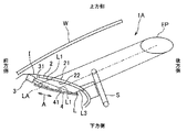
以下、本発明の第1実施形態を図面に基づいて説明する。図1は、本発明の第1実施形態に係る車両用表示装置1Aを示す側面図であり、図2は、車両用表示装置1Aにおいて光が進行する様子を模式的に示す側面図であり、図3は、車両用表示装置1Aのプロジェクタ3による投影画像の光及びスクリーン2における表示画像の光の強度分布を示すグラフである。
<First Embodiment>
DESCRIPTION OF EXEMPLARY EMBODIMENTS Hereinafter, a first embodiment of the invention will be described with reference to the drawings. FIG. 1 is a side view showing a vehicle display device 1A according to a first embodiment of the present invention, and FIG. 2 is a side view schematically showing how light travels in the vehicle display device 1A. FIG. 3 is a graph showing the light intensity distribution of the image projected by the
本実施形態の車両用表示装置1Aは、車両のインストルメントパネルIに設けられて画像を表示するものであって、透過型のスクリーン2と、投影手段としてのプロジェクタ3と、反射部材としてのミラー4と、を備える。尚、本実施形態における「前方側」及び「後方側」は、車両における前後方向を基準とする。また、インストルメントパネルIは、車両の補強部材や空調機、ECU、ワイヤハーネス等の部材を収容する箱状に形成されているものとする。
A vehicle display device 1A according to the present embodiment is provided on an instrument panel I of a vehicle to display an image, and includes a
スクリーン2は、シート状又は板状に形成されるとともにインストルメントパネルIにおける上方側から後方側にかけて側面の一部を構成するように設けられ、後方側に向かうにしたがって下方側に向かうように全体が傾斜している。スクリーン2の表示面21がインストルメントパネルIの外側に向けられ、背面22がインストルメントパネルIの内側に向けられている。また、スクリーン2は全体が上方側に向かって凸に若干湾曲しており、下方側(後方側)に向かうにしたがって曲率が大きくなっている。
The
プロジェクタ3は、インストルメントパネルIの内側に収容されるとともに、後方側からやや下方側に向いた方向を進行方向として投影光Lを投射する。投影光Lは、所定の領域(投影領域)を有している。投影光Lは進行するにしたがって投射領域が広がるものであって、投射領域の中心部と縁部とで光の進行方向が若干異なっている。以下における「投影光Lの進行方法」は、光軸LAの方向を示すものとする。
The
ミラー4は、板状に形成され、インストルメントパネルI内においてスクリーン2の背面22に近接するとともに、スクリーン2と略平行となるように対向配置され、後述するようにプロジェクタ3による投影光をスクリーン2に向けて反射するように設けられている。即ち、ミラー4はスクリーン2の下方側且つやや前方側に配置されている。尚、ミラー4は平板状ではないものの、スクリーン2及びミラー4において前方側端部と後方側端部とを結ぶ方向が互いに略平行となっており、これをスクリーン2とミラー4とが略平行であるという。また、ミラー4の上面が反射面41となり、反射面41は、後方側に向かうにしたがって曲率が大きくなる(即ち曲率半径が小さくなる)非球面状の凹曲面となっている。さらに、ミラー4の面内方向のうち、スクリーン2とミラー4との間における投影光Lの進行方向に沿った方向(前方側端部と後方側端部とを結ぶ方向)を傾斜方向Aとする。
The
ここで、スクリーン2とプロジェクタ3とミラー4との詳細な位置関係について説明する。プロジェクタ3の投射面31は、スクリーン2とミラー4との対向方向において、スクリーン2とミラー4との間に位置するとともに、対向方向におけるスクリーン2及びミラー4の中間位置と傾斜方向Aにおいて並ぶように設けられている。尚、傾斜方向Aは、スクリーン2とミラー4との対向方向に略直交している。また、スクリーン2の背面22とミラー4の反射面41との間隔は、ミラー4の傾斜方向A寸法よりも狭く、本実施形態では、例えば傾斜方向A寸法の10〜30%程度となっている。
Here, a detailed positional relationship among the
以上のようにスクリーン2とプロジェクタ3とミラー4とが配置されることで、投影光Lは次のように進行する。即ち、プロジェクタ3が投射する投影光Lは、スクリーン2とミラー4との間において、傾斜方向Aから下方側(ミラー4側)に角度θ1だけ傾斜した方向に沿って進行する。この角度θ1は、ミラー4とプロジェクタ3との相対位置、及び、ミラー4の傾斜方向A寸法に応じて設定されており、例えば10〜20°となっている。
By arranging the
このように投射された投影光Lは、ミラー4の反射面41に斜入射して反射されてスクリーン2に対して背面22から入射し、表示面21において拡散される。このように拡散された光の一部が搭乗者のアイポイントEPに届くことで、スクリーン2における表示画像が視認される。本実施形態では、アイポイントEPとスクリーン2との間にステアリングホイールSが位置しているが、ステアリングホイールSとスクリーン2との位置関係は適宜に設定されていればよい。
The projection light L projected in this way is obliquely incident on the
ここで、投影光Lは、角度θ2の広がりを有して進行する、即ち、光軸LAに対し、表示領域の上端に対応する上端光L2及び下端に対応する下端光L3は、角度θ2の1/2だけ傾斜している。反射面41の中心部で反射される光がスクリーン2における表示画像の中心に対応した中心光L1となり、上端光L2は反射面41の前方側端部(上端部)において反射され、下端光L3は反射面41の後方側端部(下端部)において反射される。また、光軸LAよりも後方側(下方側)の光が中心光L1となる。
Here, the projection light L travels with a spread of the angle θ2, that is, the upper end light L2 corresponding to the upper end of the display area and the lower end light L3 corresponding to the lower end with respect to the optical axis LA have an angle θ2. It is inclined by 1/2. The light reflected at the center of the reflecting
反射面41で反射された中心光L1と上端光L2と下端光L3とは、互いに略平行に進行し、これらの間の光も反射面41による反射後に略平行に進行する。即ち、反射面41は、入射時の進行方向が異なる光が反射後に略平行に進行するように非球面状に形成されている。投影光Lがミラー4による反射後に上記のように進行することで、スクリーン2における表示画像の傾斜方向A寸法は、ミラー4の反射範囲における傾斜方向A寸法と同程度となる。
The central light L1, the upper end light L2, and the lower end light L3 reflected by the
次に、プロジェクタ3が投影する画像(投影画像)における光の強度分布と、スクリーン2上の表示画像の表示領域における光の強度分布と、について説明する。図3は、投影領域及び表示領域の前後方向における光の強度分布を示すグラフであるが、車両の幅方向においても同様の分布となる。図3のグラフの横軸は、左側が投影領域の上端側及び表示領域の前方側に対応し、右側が投影領域の下端側及び表示領域の後方側に対応する。また、左側の縦軸が投影画像の光の強度を示し、右側の縦軸が表示画像の光の強度を示す。
Next, the light intensity distribution in the image (projected image) projected by the
プロジェクタ3は、図3に実線で示すように、投影領域における中心部に近いほど強度が低い(即ち、中心光L1の強度が上端光L2及び下端光L3の強度よりも低い)画像を投射する。即ち、予めソフト的に強度変調された画像を投射する。投影光Lが進行して投影領域が広がっていった場合に、中心部から遠い位置(縁部)ほど光の強度が低下しやすいことから、図3に実線で示すように、スクリーン2上の表示画像においては、表示領域全体において光の強度が略一定となる。一方、図3に二点鎖線で示すように、投影領域全体において光の強度が略一定となった画像を投射すると、スクリーン2上の表示画像においては端部の光の強度が中心部の光の強度よりも低くなってしまう。
As shown by a solid line in FIG. 3, the
このような本実施形態によれば、以下のような効果がある。即ち、ミラー4がスクリーン2の背面22に近接して対向配置されることで、インストルメントパネルIにおける車両用表示装置1Aの設置スペースを小さくすることができる。また、投影光Lがスクリーン2とミラー4との間を進行してミラー4に対して斜入射することで、上端光L2と下端光L3とに光路長の差が生じ、ミラー4によって反射された投影光Lには歪みが生じ、傾斜方向Aに沿った方向に引き伸ばされた像がスクリーン2に投影される。従って、設置スペースを小さくしつつ、スクリーン2における表示画像を大型化することができる。
According to this embodiment, there are the following effects. That is, since the
さらに、ミラー4の反射面41が後方側に向かうにしたがって曲率が大きくなる非球面状の凹曲面であり、反射面41で反射された中心光L1と上端光L2と下端光L3とが互いに略平行に進行することで、スクリーン2上の表示画像の後方側の部分ほど拡大されてしまうことを抑制することができる。
Furthermore, the reflecting
<第2実施形態>
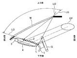
以下、本発明の第2実施形態を図面に基づいて説明する。図4は、本発明の第2実施形態に係る車両用表示装置1Bを示す側面図であり、図5は、車両用表示装置1BにおいてウインドシールドWを通して外光が照射する様子を模式的に示す側面図である。本実施形態の車両用表示装置1Bは、スクリーン2Bと、プロジェクタ3と、ミラー4と、を備える。
Second Embodiment
Hereinafter, a second embodiment of the present invention will be described with reference to the drawings. FIG. 4 is a side view showing the vehicle display device 1B according to the second embodiment of the present invention, and FIG. 5 schematically shows a state in which external light is irradiated through the windshield W in the vehicle display device 1B. It is a side view. The
スクリーン2Bには、規制部としての複数の黒色層23が設けられている。黒色層23は、表示面21から背面22にかけて、ミラー4によって反射された投影光Lの進行方向に沿って延びている。従って、スクリーン2Bにおける黒色層23が設けられていない部分が導光部24となり、投影光Lの進行方向を表示方向(スクリーン2Bから搭乗者のアイポイントに向かう方向)として、導光部24において表示方向に沿って進行する光がスクリーン2Bを通過することができる。一方、表示方向以外の方向に沿って進行する光は、黒色層23によって吸収され、スクリーン2Bを通過することが規制される。
The
具体的には、図5に示すように、ウインドシールドWを通して車両内に外光LOが照射されることがある。このような外光LOは、前方側から後方側に斜め下方に向かって進行したり、上方側から下方側に向かって進行したりする。このような進行方向を有する外光LOは黒色層23に吸収されることでスクリーン2Bの表示面21で拡散されにくい。また、ウインドシールドWの上端部から前方側に斜め下方に向かって進行する外光LOも考えられるが、ウインドシールドWの上端はアイポイントEPよりも前方側且つ上方側に位置することから、このような外光LOは、スクリーン2BからアイポイントEPに向かう表示方向とは平行にはならず、黒色層23によって吸収される。
Specifically, as shown in FIG. 5, external light LO may be irradiated into the vehicle through the windshield W. Such external light LO travels diagonally downward from the front side to the rear side, or travels downward from the upper side. The external light LO having such a traveling direction is hardly diffused on the
このような本実施形態によれば、以下のような効果がある。即ち、スクリーン2Bに黒色層23及び導光部24が設けられていることで、スクリーン2Bに表示された画像による光を搭乗者に届かせるとともに、外光を黒色層23に吸収させてスクリーン2Bにおいて拡散されることを抑制し、表示画像を視認させやすくすることができる。
According to this embodiment, there are the following effects. That is, the
なお、本発明は、前記第1実施形態及び第2実施形態に限定されるものではなく、本発明の目的が達成できる他の構成等を含み、以下に示すような変形等も本発明に含まれる。 The present invention is not limited to the first embodiment and the second embodiment, and includes other configurations that can achieve the object of the present invention. The following modifications and the like are also included in the present invention. It is.
例えば、前記第1実施形態では、プロジェクタ3から投射された投影光Lが直接ミラー4に向かうものとしたが、プロジェクタ3によって投射された投影光Lをミラー4に向けて反射する少なくとも1つの補助反射部をさらに備えていてもよい。
For example, in the first embodiment, the projection light L projected from the
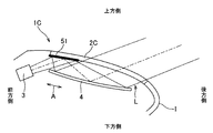
即ち、第1の変形例として図6に示すように、車両用表示装置1Cが、スクリーン2Cと、プロジェクタ3と、ミラー4と、スクリーン2Cの背面に設けられた補助反射部51と、を備える構成としてもよい。このような車両用表示装置1Cでは、プロジェクタ3が補助反射部51の前方側且つ下方側に設けられ、補助反射部51に向けて投影光Lを投射する。投影光Lは、補助反射部51によって反射されるとともに、補助反射部51を起点として、スクリーン2Cとミラー4との間において、傾斜方向Aからミラー4側に傾斜した方向に沿って進行し、ミラー4によって反射されてスクリーン2Cに向かう。
That is, as shown in FIG. 6 as a first modification, the vehicle display device 1C includes a screen 2C, a
また、第2の変形例として図7に示すように、車両用表示装置1Dが、スクリーン2と、プロジェクタ3と、ミラー4と、第1実施形態のプロジェクタ3と略同一位置に設けられた補助反射部52と、を有する構成としてもよい。このような車両用表示装置1Dでは、プロジェクタ3が補助反射部52の前方側且つ下方側に設けられ、補助反射部52に向けて投影光Lを投射する。投影光Lは、第1の変形例と同様に進行する。
Further, as shown in FIG. 7 as a second modified example, the
また、第3の変形例として図8に示すように、車両用表示装置1Eが、スクリーン2と、プロジェクタ3と、ミラー4と、2つの補助反射部53、54と、を有する構成としてもよい。このような車両用表示装置1Eでは、一方(プロジェクタ3側)の補助反射部53は、第2の変形例の補助反射部52と略同一位置に設けられ、他方(ミラー4側)の補助反射部54は、第1実施形態のプロジェクタ3と略同一位置に設けられている。また、プロジェクタ3が一方の補助反射部53の後方側且つ下方側に設けられ、補助反射部53に向けて投影光Lを投射する。投影光Lは、一方の補助反射部53によって反射されて他方の補助反射部54に向かった後、第2の変形例と同様に進行する。
Further, as shown in FIG. 8 as a third modified example, the
以上のように補助反射部をさらに備える構成とすれば、プロジェクタ3の配置の自由度を向上させることができる。
As described above, when the auxiliary reflection unit is further provided, the degree of freedom in arranging the
また、前記実施形態では、ミラー4の反射面41が非球面状の凹曲面であるものとしたが、第4の変形例の車両用表示装置1Fとして図9に示すように、平面状の反射面42を有するミラー4Fを備えるものとしてもよい。このような車両用表示装置1Fでは、反射面42が平面であるため、前述のように表示画像の下方側が拡大されやすい。即ち、ミラー4Fによる反射後に中心光L1が上端光L2側に寄り、中心光L1の延長線が、表示画像の中心を示す表示中心よりも上方に位置する。このとき、ミラー4の反射によって表示画像がどのように拡大されるかを予め計算したり実験的に検証したりしておき、拡大の程度に応じて投影領域の下方側が予め縮小された画像をプロジェクタによって投射することにより、表示画像を調節すればよい。
Moreover, in the said embodiment, although the
その他、本発明を実施するための最良の構成、方法などは、以上の記載で開示されているが、本発明は、これに限定されるものではない。すなわち、本発明は、主に特定の実施形態に関して特に図示され、且つ、説明されているが、本発明の技術的思想および目的の範囲から逸脱することなく、以上述べた実施形態に対し、形状、材質、数量、その他の詳細な構成において、当業者が様々な変形を加えることができるものである。従って、上記に開示した形状、材質などを限定した記載は、本発明の理解を容易にするために例示的に記載したものであり、本発明を限定するものではないから、それらの形状、材質などの限定の一部、もしくは全部の限定を外した部材の名称での記載は、本発明に含まれるものである。 In addition, the best configuration, method and the like for carrying out the present invention have been disclosed in the above description, but the present invention is not limited to this. That is, the invention has been illustrated and described primarily with respect to particular embodiments, but may be configured for the above-described embodiments without departing from the scope and spirit of the invention. Various modifications can be made by those skilled in the art in terms of materials, quantity, and other detailed configurations. Therefore, the description limiting the shape, material, etc. disclosed above is an example for easy understanding of the present invention, and does not limit the present invention. The description by the name of the member which remove | excluded the limitation of one part or all of such is included in this invention.
1A〜1F 車両用表示装置
2、2B、2C スクリーン
3 プロジェクタ(投影手段)
4、4F ミラー(反射部材)
21 表示面
22 背面
23 黒色層(規制部)
24 導光部
41、42 反射面
51〜54 補助反射部
L 投影光
I インストルメントパネル
1A-1F
4, 4F mirror (reflective member)
21
24
Claims (3)
表示面が前記インストルメントパネルの外側に向くように設けられた透過型のスクリーンと、
前記インストルメントパネル内に収容された投影手段と、
前記インストルメントの内側において前記スクリーンの背面に対向配置されるとともに前記投影手段による投影光を当該スクリーンに向けて反射する反射部材と、を備え、
前記投影光は、前記スクリーンと前記反射部材との間を進行するとともに当該反射部材に対して斜入射し、
前記スクリーンと前記反射部材とは、当該反射部材の面内方向のうち前記投影光の進行方向に沿った方向の寸法よりも間隔が狭くなるように配置され、
前記反射部材の反射面は、前記スクリーンと前記反射部材との間を進行する前記投影光の起点から遠ざかるほど曲率が大きくなる凹曲面であり、
前記反射部材に入射する前記投影光の光軸の方向は、前記反射部材の両端部を結ぶ傾斜方向に対して10〜20°傾斜していることを特徴とする車両用表示装置。 A vehicle display device that is provided on an instrument panel of a vehicle and displays an image,
A transmissive screen provided with a display surface facing the outside of the instrument panel;
Projection means housed in the instrument panel;
A reflective member disposed opposite to the back surface of the screen inside the instrument and reflecting the projection light from the projection means toward the screen,
The projection light travels between the screen and the reflecting member and is obliquely incident on the reflecting member,
The screen and the reflecting member are arranged so that the interval is narrower than the dimension in the direction along the traveling direction of the projection light in the in-plane direction of the reflecting member ,
The reflecting surface of the reflecting member is a concave curved surface whose curvature increases as the distance from the starting point of the projection light traveling between the screen and the reflecting member increases.
The vehicular display device , wherein the direction of the optical axis of the projection light incident on the reflecting member is inclined by 10 to 20 degrees with respect to an inclination direction connecting both end portions of the reflecting member .
Priority Applications (1)
| Application Number | Priority Date | Filing Date | Title |
|---|---|---|---|
| JP2015207243A JP6590635B2 (en) | 2015-10-21 | 2015-10-21 | Vehicle display device |
Applications Claiming Priority (1)
| Application Number | Priority Date | Filing Date | Title |
|---|---|---|---|
| JP2015207243A JP6590635B2 (en) | 2015-10-21 | 2015-10-21 | Vehicle display device |
Publications (2)
| Publication Number | Publication Date |
|---|---|
| JP2017078807A JP2017078807A (en) | 2017-04-27 |
| JP6590635B2 true JP6590635B2 (en) | 2019-10-16 |
Family
ID=58665336
Family Applications (1)
| Application Number | Title | Priority Date | Filing Date |
|---|---|---|---|
| JP2015207243A Active JP6590635B2 (en) | 2015-10-21 | 2015-10-21 | Vehicle display device |
Country Status (1)
| Country | Link |
|---|---|
| JP (1) | JP6590635B2 (en) |
-
2015
- 2015-10-21 JP JP2015207243A patent/JP6590635B2/en active Active
Also Published As
| Publication number | Publication date |
|---|---|
| JP2017078807A (en) | 2017-04-27 |
Similar Documents
| Publication | Publication Date | Title |
|---|---|---|
| JP6234339B2 (en) | Head-up display device for vehicle | |
| US8760766B2 (en) | Head-up display apparatus | |
| US7652825B2 (en) | Cover for head-up display | |
| US11448877B2 (en) | Projection optical system and head-up display | |
| JP2008195194A (en) | Vehicular display device | |
| KR101484204B1 (en) | Cover of Head up Display and housing including the same | |
| JP6510578B2 (en) | Head-up display device | |
| JP2012148668A (en) | Defroster blowout port | |
| JP5778714B2 (en) | Projection system | |
| JP7122517B2 (en) | In-vehicle display device | |
| JP6879299B2 (en) | Display device | |
| WO2013128615A1 (en) | Head-up display | |
| JP6590635B2 (en) | Vehicle display device | |
| JP6925891B2 (en) | Display device and interior member unit | |
| JP2004101829A (en) | Head-up display for vehicle | |
| US20120007381A1 (en) | Glass for a vehicle dashboard | |
| JP2015045690A (en) | Head-up display and projection device | |
| JP6527849B2 (en) | Display device and interior member unit | |
| JP7143264B2 (en) | vehicle display | |
| WO2013051086A1 (en) | Headup display | |
| EP3932718A1 (en) | Display device, head-up display, moving body, and light guide panel | |
| JP2006290102A (en) | Projecting indication device and method for vehicle | |
| JP2013539057A (en) | Display device and display method | |
| JP7435337B2 (en) | cover member | |
| EP3859428A1 (en) | Head-up display device |
Legal Events
| Date | Code | Title | Description |
|---|---|---|---|
| RD04 | Notification of resignation of power of attorney |
Free format text: JAPANESE INTERMEDIATE CODE: A7424 Effective date: 20180208 |
|
| RD04 | Notification of resignation of power of attorney |
Free format text: JAPANESE INTERMEDIATE CODE: A7424 Effective date: 20180817 |
|
| A621 | Written request for application examination |
Free format text: JAPANESE INTERMEDIATE CODE: A621 Effective date: 20180919 |
|
| A131 | Notification of reasons for refusal |
Free format text: JAPANESE INTERMEDIATE CODE: A131 Effective date: 20190625 |
|
| A977 | Report on retrieval |
Free format text: JAPANESE INTERMEDIATE CODE: A971007 Effective date: 20190626 |
|
| A521 | Request for written amendment filed |
Free format text: JAPANESE INTERMEDIATE CODE: A523 Effective date: 20190820 |
|
| TRDD | Decision of grant or rejection written | ||
| A01 | Written decision to grant a patent or to grant a registration (utility model) |
Free format text: JAPANESE INTERMEDIATE CODE: A01 Effective date: 20190910 |
|
| A61 | First payment of annual fees (during grant procedure) |
Free format text: JAPANESE INTERMEDIATE CODE: A61 Effective date: 20190917 |
|
| R150 | Certificate of patent or registration of utility model |
Ref document number: 6590635 Country of ref document: JP Free format text: JAPANESE INTERMEDIATE CODE: R150 |
|
| R250 | Receipt of annual fees |
Free format text: JAPANESE INTERMEDIATE CODE: R250 |
|
| S531 | Written request for registration of change of domicile |
Free format text: JAPANESE INTERMEDIATE CODE: R313531 |
|
| R350 | Written notification of registration of transfer |
Free format text: JAPANESE INTERMEDIATE CODE: R350 |
|
| R250 | Receipt of annual fees |
Free format text: JAPANESE INTERMEDIATE CODE: R250 |