JP6587473B2 - Vehicle seat and method for manufacturing vehicle seat - Google Patents
Vehicle seat and method for manufacturing vehicle seat Download PDFInfo
- Publication number
- JP6587473B2 JP6587473B2 JP2015181569A JP2015181569A JP6587473B2 JP 6587473 B2 JP6587473 B2 JP 6587473B2 JP 2015181569 A JP2015181569 A JP 2015181569A JP 2015181569 A JP2015181569 A JP 2015181569A JP 6587473 B2 JP6587473 B2 JP 6587473B2
- Authority
- JP
- Japan
- Prior art keywords
- skin material
- vehicle seat
- pattern
- trim cover
- wadding
- Prior art date
- Legal status (The legal status is an assumption and is not a legal conclusion. Google has not performed a legal analysis and makes no representation as to the accuracy of the status listed.)
- Active
Links
- 238000004519 manufacturing process Methods 0.000 title claims description 27
- 238000000034 method Methods 0.000 title claims description 19
- 239000000463 material Substances 0.000 claims description 82
- 238000010438 heat treatment Methods 0.000 claims description 30
- 238000003825 pressing Methods 0.000 claims description 28
- 239000004831 Hot glue Substances 0.000 claims description 14
- 239000002648 laminated material Substances 0.000 claims description 13
- 239000010985 leather Substances 0.000 claims description 13
- 239000000853 adhesive Substances 0.000 claims description 12
- 230000001070 adhesive effect Effects 0.000 claims description 12
- 239000004744 fabric Substances 0.000 claims description 11
- 238000009958 sewing Methods 0.000 description 25
- 239000011162 core material Substances 0.000 description 3
- 238000005520 cutting process Methods 0.000 description 3
- 238000010586 diagram Methods 0.000 description 3
- 230000000694 effects Effects 0.000 description 3
- 238000002360 preparation method Methods 0.000 description 3
- DQXBYHZEEUGOBF-UHFFFAOYSA-N but-3-enoic acid;ethene Chemical compound C=C.OC(=O)CC=C DQXBYHZEEUGOBF-UHFFFAOYSA-N 0.000 description 2
- 239000005038 ethylene vinyl acetate Substances 0.000 description 2
- 239000012943 hotmelt Substances 0.000 description 2
- 239000002649 leather substitute Substances 0.000 description 2
- 238000002844 melting Methods 0.000 description 2
- 230000008018 melting Effects 0.000 description 2
- 229920001200 poly(ethylene-vinyl acetate) Polymers 0.000 description 2
- 238000004904 shortening Methods 0.000 description 2
- 239000007787 solid Substances 0.000 description 2
- 239000002759 woven fabric Substances 0.000 description 2
- 238000010521 absorption reaction Methods 0.000 description 1
- 238000005452 bending Methods 0.000 description 1
- 230000015572 biosynthetic process Effects 0.000 description 1
- 238000001816 cooling Methods 0.000 description 1
- 238000006073 displacement reaction Methods 0.000 description 1
- 238000010030 laminating Methods 0.000 description 1
- 239000007788 liquid Substances 0.000 description 1
- 238000012986 modification Methods 0.000 description 1
- 230000004048 modification Effects 0.000 description 1
- 239000012466 permeate Substances 0.000 description 1
- 238000003672 processing method Methods 0.000 description 1
- 239000000047 product Substances 0.000 description 1
- 230000007261 regionalization Effects 0.000 description 1
- 238000007790 scraping Methods 0.000 description 1
- 229920005992 thermoplastic resin Polymers 0.000 description 1
- 238000009966 trimming Methods 0.000 description 1
- 210000000689 upper leg Anatomy 0.000 description 1
- 238000009941 weaving Methods 0.000 description 1
- 230000037303 wrinkles Effects 0.000 description 1
Images


Classifications
-
- B—PERFORMING OPERATIONS; TRANSPORTING
- B60—VEHICLES IN GENERAL
- B60N—SEATS SPECIALLY ADAPTED FOR VEHICLES; VEHICLE PASSENGER ACCOMMODATION NOT OTHERWISE PROVIDED FOR
- B60N2/00—Seats specially adapted for vehicles; Arrangement or mounting of seats in vehicles
- B60N2/58—Seat coverings
-
- B—PERFORMING OPERATIONS; TRANSPORTING
- B68—SADDLERY; UPHOLSTERY
- B68G—METHODS, EQUIPMENT, OR MACHINES FOR USE IN UPHOLSTERING; UPHOLSTERY NOT OTHERWISE PROVIDED FOR
- B68G7/00—Making upholstery
Landscapes
- Engineering & Computer Science (AREA)
- Mechanical Engineering (AREA)
- Aviation & Aerospace Engineering (AREA)
- Transportation (AREA)
- Manufacturing & Machinery (AREA)
- Seats For Vehicles (AREA)
Description
本発明は、車両用シートに係り、特に、トリムカバーに意匠(デザイン)を施す際に適用して有効な技術に関する。 The present invention relates to a vehicle seat, and more particularly to a technique that is effective when applied to a design (design) on a trim cover.
自動車シートなどの車両用シートは安全性やホールド性、乗降性(乗り降りのしやすさ)など様々な機能が求められると同時に、座り心地や振動吸収性能といった乗員の快適性向上に対する要求も多い。また、自動車の内装部品のなかでも目を引く大きなパーツであり、その外観やデザインについても様々な要求がある。 Vehicle seats such as automobile seats are required to have various functions such as safety, holdability, and getting on and off (ease of getting on and off), and at the same time, there are many demands for improving passenger comfort such as sitting comfort and vibration absorption performance. In addition, it is a large part that attracts attention among the interior parts of automobiles, and there are various demands on its appearance and design.
自動車シートの意匠表現としてシートカバーであるトリムカバーに意匠(デザイン)を施す場合、トリムカバーを縫製する前の裁断ピースの状態で、例えばミシン縫いにより刺繍を施す等の加工を行っている。 When a design (design) is applied to a trim cover, which is a seat cover, as a design expression of an automobile seat, processing such as embroidery is performed in a state of a cut piece before sewing the trim cover, for example, by sewing.
本技術分野の背景技術として、例えば、特許文献1のような技術がある。特許文献1には、「表皮材として用いる皮革の裏面側から肉厚を所定のパターンに応じて所望厚み削り取り、その薄肉部分を撓み変形させて表面側に所定形状の皺模様を付形したトリムカバー」が開示されている。
As a background art in this technical field, for example, there is a technique such as
また、特許文献2には、「模様用紐を、略クロス状態でライン状に配置して、メッシュ織りラインを形成した自動車用シート」が開示されている。
また、特許文献3には、「準備工程で立体模様の施された皮革素材を準備し、保形処理工程では、皮革素材は、所定の加熱蒸気に晒された状態で、裏面側には芯地を貼付け、皮革素材の表面側は弾性力のある平坦な支持面に載せられて芯地の上面から加圧される皮革素材の立体模様加工方法」が開示されている。 Patent Document 3 states that “a leather material with a three-dimensional pattern is prepared in the preparation process, and in the shape-retaining treatment process, the leather material is exposed to a predetermined heating steam and has a core on the back side. A method of processing a three-dimensional pattern of a leather material in which a ground is pasted and the surface side of the leather material is placed on a flat support surface having elasticity and pressed from the upper surface of the interlining is disclosed.
上記のように、トリムカバーを縫製する前の裁断ピースの状態で、例えばミシン縫いにより刺繍を施す場合、刺繍加工用のコンピュータミシンの導入が必要となり、刺繍加工のための多くの時間も必要とすることから、製造コストの上昇やリードタイムの増加に繋がる。 As described above, when embroidery is performed in the state of the cut piece before the trim cover is sewn, for example, by sewing the sewing machine, it is necessary to introduce a computer sewing machine for embroidery processing, and much time is required for embroidery processing. This leads to an increase in manufacturing cost and an increase in lead time.
また、顧客の要求に応じた意匠(デザイン)を施した裁断ピースを揃える必要があり、裁断ピースの種類も多くなり、在庫管理が煩雑になる。 In addition, it is necessary to prepare cutting pieces that have been subjected to a design (design) according to a customer's request, and the types of cutting pieces increase, making inventory management complicated.
さらに、裁断ピースに意匠(デザイン)を施した後に、裁断ピースを縫製してトリムカバーを成形するため、表皮材の裁断時のバラツキや縫製時の裁断ピースの縫製時のバラツキにより、トリムカバー毎に意匠のズレが生じてしまう恐れもある。 In addition, since the trim cover is formed by sewing the cut piece after the design (design) is applied to the cut piece, each trim cover is subject to variations due to variations in the cut of the skin material and variations in the cut piece during sewing. There is also a risk that the design will shift.
上記特許文献1のトリムカバーの製造方法は、表皮材の表面に皺模様を形成するものであるが、表皮材の裏面側の一部を削り取る必要があるため、意匠(デザイン)設計の自由度が低く、また、製造コストの抑制やリードタイムの短縮には不利である。
The manufacturing method of the trim cover of
上記特許文献2の表皮模様構造は、斬新なメッシュ織ラインを形成できる反面、作業が煩雑で、やはり製造コストの抑制やリードタイムの短縮には不利である。
The skin pattern structure of
上記特許文献3の立体模様加工方法は、準備工程において予め立体模様を加工するため、準備工程において形成した立体模様が保形処理されるまでの間に型崩れしてしまう恐れがあり、バラツキの少ない均一な品質が求められる自動車シートのような量産品の製造には不向きである。また、弾性力のある平坦な支持面を準備する必要もあり、製造コストやリードタイムの面においても不利である。 Since the three-dimensional pattern processing method of Patent Document 3 processes a three-dimensional pattern in advance in the preparation process, there is a risk that the three-dimensional pattern formed in the preparation process may lose shape before the shape-retaining treatment is performed. It is unsuitable for manufacturing mass-produced products such as automobile seats that require a small and uniform quality. Further, it is necessary to prepare a flat support surface having elasticity, which is disadvantageous in terms of manufacturing cost and lead time.
そこで、本発明の目的は、型崩れが生じ難く耐久性の高い立体模様が表面に施された車両用シートを提供することにある。 SUMMARY OF THE INVENTION An object of the present invention is to provide a vehicle seat having a highly durable three-dimensional pattern on its surface that is not easily deformed.
また、本発明の別の目的は、製造コストおよびリードタイムの上昇を抑制しつつ、意匠(デザイン)設計の自由度が高く座り心地に影響の少ない立体模様を有する車両用シートの製造方法を提供することにある。 Another object of the present invention is to provide a method for manufacturing a vehicle seat having a three-dimensional pattern that has a high degree of freedom in design (design) and has little influence on sitting comfort while suppressing an increase in manufacturing cost and lead time. There is to do.
また、本発明は、(a)下層から順に、ワディング、熱溶融型接着材、革系素材からなる表皮材を重ね合わせて積層材料を準備する工程、(b)所望の模様が形成された押し型を前記表皮材側から押し当てて、前記積層材料を加圧する工程、(c)前記積層材料を加圧した状態のまま、前記表皮材の裏面側から加熱蒸気を供給し当該加圧部を加熱する工程、を含む車両用シートの製造方法である。 The present invention also includes (a) a step of preparing a laminated material by laminating a skin material made of a wadding, a hot-melt adhesive, and a leather-based material in order from the lower layer, and (b) a pressing with a desired pattern formed A step of pressing the laminate material by pressing a mold from the skin material side; (c) supplying heated steam from the back surface side of the skin material while pressing the laminate material; A vehicle seat manufacturing method including a heating step.
また、本発明は、(a)ワディングおよび革系素材からなる表皮材の積層材料からなるトリムカバーを準備する工程、(b)前記トリムカバーのワディング側表面に熱溶融型接着材を介して、裏基布材を重ね合わせる工程、(c)所望の模様が形成された押し型を前記トリムカバーの表皮材側から押し当てて、前記トリムカバーを加圧する工程、(d)前記トリムカバーを加圧した状態のまま、前記表皮材の裏面側から加熱蒸気を供給し当該加圧部を加熱する工程、を含む車両用シートの製造方法である。
In addition, the present invention provides (a) a step of preparing a trim cover made of a laminated material of a skin material made of wadding and leather-based material , and (b) a hot melt adhesive on the wadding side surface of the trim cover, (C) a step of pressing the trim cover by pressing a pressing mold on which a desired pattern is formed from the skin material side, and (d) adding the trim cover. The vehicle seat manufacturing method includes a step of supplying heated steam from the back surface side of the skin material and heating the pressurizing portion in a pressed state.
本発明によれば、型崩れが生じ難く耐久性の高い立体模様が表面に施された車両用シートを実現できる。 According to the present invention, it is possible to realize a vehicle seat having a highly durable three-dimensional pattern that is less likely to lose its shape.
また、本発明によれば、製造コストおよびリードタイムの上昇を抑制しつつ、意匠(デザイン)設計の自由度が高く座り心地に影響の少ない立体模様を有する車両用シートの製造方法を提供することができる。 In addition, according to the present invention, there is provided a method for manufacturing a vehicle seat having a three-dimensional pattern having a high degree of freedom in design (design) and having little influence on sitting comfort while suppressing an increase in manufacturing cost and lead time. Can do.
上記した以外の課題、構成及び効果は、以下の実施形態の説明により明らかにされる。 Problems, configurations, and effects other than those described above will be clarified by the following description of embodiments.
以下、図面を用いて本発明の実施例を説明する。なお、各図面において、同一の構成については同一の符号を付し、重複する部分についてはその詳細な説明は省略する。 Embodiments of the present invention will be described below with reference to the drawings. In the drawings, the same components are denoted by the same reference numerals, and detailed description of the overlapping portions is omitted.
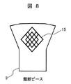
先ず、図8を参照して、従来の自動車シートの表面に施された模様について説明する。図8は自動車シートに用いられる表皮材の裁断ピース表面に格子状のミシン縫い(刺繍)15が施された図である。 First, with reference to FIG. 8, the pattern given to the surface of the conventional motor vehicle seat is demonstrated. FIG. 8 is a view in which a lattice-like sewing sewing (embroidery) 15 is applied to the surface of a cut piece of a skin material used for an automobile seat.
従来の自動車シートでは、シート表面に模様を形成する場合、図8のように、表皮材9の裁断ピースに直接ミシン縫い(刺繍)を施し、加工するのが一般的である。この方法は、自動車シートの表面に平面的な模様を形成するのに向いており、例えば、コンピュータミシンに複数の模様(パターン)を予め記憶させておき、所望の模様(パターン)を選択することで、表皮材9の表面にミシン縫い(刺繍)15を施すことで模様を形成する。
In a conventional automobile seat, when a pattern is formed on the sheet surface, as shown in FIG. 8, it is common to perform sewing by sewing (embroidery) directly on the cut piece of the
従来のミシン縫い(刺繍)による模様の形成は、上述したように、高額なコンピュータミシンの導入が必要となり、自動車シートの製造コストの上昇に繋がる。また、複雑な模様を形成する場合、ミシン縫い(刺繍)に時間が掛かり、リードタイムが増加してしまう。また、自動車シートの場合、着座した乗員の衣服とミシン縫い(刺繍)が接触し、摩擦によりミシン縫い(刺繍)が摩耗してしまう恐れもある。また、ミシン縫い(刺繍)で立体的な模様を形成する場合、加工できる模様(形)には制限があり、製造コストやリードタイムもさらに上昇してしまう。 Conventional pattern formation by sewing (embroidery) requires introduction of an expensive computer sewing machine as described above, leading to an increase in the manufacturing cost of automobile seats. Further, when forming a complicated pattern, it takes time for sewing (embroidery), and the lead time increases. In the case of an automobile seat, the occupant's clothes seated and the sewing machine (embroidery) may come into contact with each other, and the sewing machine (embroidery) may be worn due to friction. In addition, when a three-dimensional pattern is formed by sewing (embroidery), there is a limit to the pattern (shape) that can be processed, and the manufacturing cost and lead time are further increased.
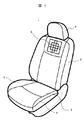
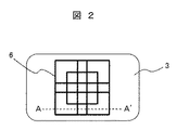
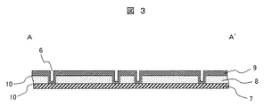
次に、図1から図3を用いて、本実施例における車両用シートについて説明する。図1は本実施例の車両用シート1の全体概要を示す斜視図である。図2は図1における模様(溝)6が形成された箇所のシートバック3の拡大図である。また、図3は図2のA−A’部断面の拡大図である。
Next, the vehicle seat in the present embodiment will be described with reference to FIGS. 1 to 3. FIG. 1 is a perspective view showing an overall outline of a
車両用シート1は、図1に示すように、シートの座面部となるシートクッション2が図示しないシートフレーム上に設けられている。シートクッション2の背側には、シートの背もたれ部となるシートバック3が図示しないリクライニング機構を介して設けられている。シートバック3の上部には、乗員の頭部および頸部を保護するヘッドレスト4が設けられている。シートクッション2の両脇には、着座時に乗員の大腿部を横方向から支持するサイドサポート5が設けられている。シートバック3の上部側には、凹形状の溝からなる模様6が形成されている。
As shown in FIG. 1, the
なお、図1および図2では、模様6の例として格子状の模様を用いて示しているが、これに限定されるものではなく、例えば、円形の模様や、一定の模様が規則的に配列された幾何学模様などに置き換えることも可能である。
In FIGS. 1 and 2, a lattice-like pattern is used as an example of the
図3を用いて、模様6について詳しく説明する。模様6は、図3に示すように、トリムカバーの中綿であるワディング8および表皮材9に、凹形状の溝(窪み)として形成されている。ワディング8と表皮材9は、例えば、ホットメルトのような熱溶融型の接着材10で互いに接着されている。
The
表皮材9は、本革や合成皮革などの革系素材や編物や織物などの布系素材が使用される。
The
熱溶融型の接着材10は、例えば、エチレン酢酸ビニル(Ethylene−Vinyl−Acetate)などの熱可塑性樹脂を主成分とする接着材である。常温では固形または半固形であり、高温で液体となる材料である。材料や成分に応じて、50℃〜200℃程度で加熱溶融して塗布し、冷却することにより固化して接着材として機能する。
The hot-
図3において、凹形状の溝(窪み)が形成されたワディング8および表皮材9は、車両用シートのシートカバーとなるトリムカバーを構成する。少なくとも凹形状の溝(窪み)が形成された箇所のトリムカバーは、下層から順に、ワディング、熱溶融型接着材、表皮材の積層材料で形成されている。
In FIG. 3, the wading 8 and the
本実施例の車両用シートでは、図3に示すように、ワディング8の下層に、熱溶融型の接着材10を介して、さらにトリムカバーの芯材となる裏基布材7が接着されている。
In the vehicle seat of the present embodiment, as shown in FIG. 3, a back
図4から図5Bを用いて、上記で説明した模様6の形成方法について説明する。図4は本実施例における模様6の形成方法を概念的に示す図である。図5Aおよび図5Bは図4を工程順に分けて示す図である。
The formation method of the
図4に示すように、ワディング8、熱溶融型の接着材10、表皮材9の三層からなる積層材料に、所望の模様が形成された押し型11を表皮材9側から押し当てて加圧し、加圧した状態を維持したまま、蒸気ノズル12から加熱蒸気13を供給し、接着材10を溶融することで、ワディング8と表皮材9を接着させつつ、ワディング8および表皮材9に凹形状の溝(窪み)が形成される。この凹形状の溝(窪み)は、押し型11による加圧痕である。なお、表皮材9は図4に示すように、裁断ピースの状態のままで、押し型11による押圧と加熱蒸気13による加熱を行う。
As shown in FIG. 4, a
図5A,図5Bを用いて、上記の工程を順に説明する。図5Aに示すように、ワディング8、熱溶融型の接着材10、表皮材9の三層を重ね合わせて積層材料を準備し、表皮材9側から押し型11を所定の圧力で押圧する。
The above steps will be described in order with reference to FIGS. 5A and 5B. As shown in FIG. 5A, a laminated material is prepared by overlapping three layers of a
次に、図5Bに示すように、押し型11で押圧した状態を維持したまま、蒸気ノズル12から加熱蒸気13を加圧箇所に供給する。加熱蒸気13により熱溶融型の接着材10が溶融し、加熱蒸気13の供給停止により接着材10が冷却され、ワディング8と表皮材9が互いに接着する。これにより、ワディング8と表皮材9を互いに接着しつつ、ワディング8および表皮材9に凹形状の溝(窪み)が形成される。
Next, as shown in FIG. 5B, the
以上説明したように、本実施例によれば、型崩れが生じ難く耐久性の高い立体模様をトリムカバーの表面に形成することができる。また、コンピュータミシンなどの高額な設備投資を必要とせず、簡便な方法でトリムカバーに立体模様を形成できるため、製造コストおよびリードタイムの上昇を抑制しつつ、意匠(デザイン)設計の自由度が高く座り心地に影響の少ない立体模様を有する車両用シートを製造することができる。 As described above, according to this embodiment, it is possible to form a highly durable three-dimensional pattern on the surface of the trim cover. In addition, since a three-dimensional pattern can be formed on the trim cover by a simple method without requiring expensive capital investment such as a computer sewing machine, the degree of freedom in design (design) design is suppressed while suppressing an increase in manufacturing cost and lead time. It is possible to manufacture a vehicle seat having a three-dimensional pattern that is high and has little effect on sitting comfort.
なお、図5A,図5Bで説明したように、押し型11による積層材料の押圧は、加熱蒸気13を加圧部に供給する前に行うのがより好ましい。押し型11による押圧を行わずに加熱蒸気13を供給した場合、重ね合わせた三層の材料にズレが生じる恐れがあるためである。
As described with reference to FIGS. 5A and 5B, the pressing of the laminated material by the
また、加熱蒸気13による加熱に替えて、他の加熱手段により接着材10の溶融温度である50℃〜200℃の加熱を行っても良い。
Moreover, it may replace with the heating with the heating vapor |
図6から図7Bを用いて、模様6の別の形成方法について説明する。図6は本実施例における模様6の形成方法を概念的に示す図である。図7Aおよび図7Bは図6を工程順に分けて示す図である。
Another method for forming the
図6に示すように、本実施例では、ワディング8と表皮材9からなるトリムカバー14を予め別の工程で準備しておき、ワディング8の下層に熱溶融型の接着材10を介して芯材となる裏基布材7を重ね合わせ、所望の模様が形成された押し型11を表皮材9側から押し当てて加圧する。押し型11により加圧した状態を維持したまま、蒸気ノズル12から加熱蒸気13を供給し、接着材10を溶融することで、ワディング8と裏基布材7を接着させつつ、ワディング8および表皮材9に凹形状の溝(窪み)が形成される。
As shown in FIG. 6, in this embodiment, a
なお、トリムカバー14は図6に示すように、裁断ピースを縫製してシート形状に合わせたトリムカバーを成形した後に熱溶融型の接着材10と裏基布材7を重ね合わせ、押し型11による押圧と加熱蒸気13による加熱を行う。
As shown in FIG. 6, the
図7A,図7Bを用いて、上記の工程を順に説明する。図7Aに示すように、予め別の工程で準備したワディング8および表皮材9からなるトリムカバー14の裏面側、つまりワディング8の表面側に熱溶融型の接着材10を介して裏基布材7を重ね合わせ、表皮材9側から押し型11により所定の圧力で押圧する。
The above steps will be described in order with reference to FIGS. 7A and 7B. As shown in FIG. 7A, the back base fabric material is provided on the back surface side of the
次に、図7Bに示すように、押し型11で押圧した状態を維持したまま、蒸気ノズル12から加熱蒸気13を加圧箇所に供給する。加熱蒸気13により熱溶融型の接着材10が溶融し、加熱蒸気13の供給停止により接着材10が冷却され、ワディング8と裏基布材7が互いに接着する。これにより、トリムカバー14と裏基布材7を互いに接着しつつ、ワディング8および表皮材9に凹形状の溝(窪み)が形成される。
Next, as shown in FIG. 7B, the
以上説明したように、本実施例によれば、実施例1と同様に、型崩れが生じ難く耐久性の高い立体模様をトリムカバーの表面に形成することができる。また、コンピュータミシンなどの高額な設備投資を必要とせず、簡便な方法でトリムカバーに立体模様を形成できるため、製造コストおよびリードタイムの上昇を抑制しつつ、意匠(デザイン)設計の自由度が高く座り心地に影響の少ない立体模様を有する車両用シートを製造することができる。 As described above, according to the present embodiment, as in the first embodiment, it is possible to form a highly durable three-dimensional pattern on the surface of the trim cover, which is not easily deformed. In addition, since a three-dimensional pattern can be formed on the trim cover by a simple method without requiring expensive capital investment such as a computer sewing machine, the degree of freedom in design (design) design is suppressed while suppressing an increase in manufacturing cost and lead time. It is possible to manufacture a vehicle seat having a three-dimensional pattern that is high and has little effect on sitting comfort.
また、本実施例では、図6に示すように、裁断ピースを縫製してシート形状に合わせたトリムカバーを成形した後に、押し型11による押圧と加熱蒸気13による加熱でワディング8および表皮材9に凹形状の溝(窪み)を形成するため、裁断ピースの縫製時に生じるズレによる模様すなわち凹形状の溝(窪み)のズレを防止することができる。
Further, in this embodiment, as shown in FIG. 6, after the trim cover is formed by sewing the cut pieces to match the sheet shape, the
なお、実施例1と同様に、押し型11による積層材料の押圧は、加圧部に加熱蒸気13を供給する前に行うのがより好ましい。また、加熱蒸気13による加熱に替えて、他の加熱手段により接着材10の溶融温度である50℃〜200℃の加熱を行っても良い。
As in Example 1, it is more preferable to press the laminated material with the
また、図6から図7Bに示すように、加熱蒸気13は、表皮材9の表面側および裏面側のどちら側から供給しても良い。但し、表皮材9が本革や合成皮革など革系素材の場合、加熱蒸気13が表皮材9を透過し難いため、表皮材9の裏面側から供給するのがより好ましい。一方、表皮材9が編物や織物などの布系素材の場合は、加熱蒸気13が表皮材9を透過しやすいため、表皮材9の表面側および裏面側のどちら側から供給しても良い。
Further, as shown in FIGS. 6 to 7B, the
また、ワディング8と表皮材9からなるトリムカバー14を予め別の工程で準備しておく際、ワディング8と表皮材9の互いの接着は、熱溶融型の接着材10を用いても良く、それ以外の接着材を用いても良い。
Further, when the
上記の各実施例において、意匠(模様)がシートバックに形成される例を用いて説明したが、シートクッションやヘッドレスト、アームレスト等、シートバック以外の部位にも適用できることは言うまでもない。 In each of the above-described embodiments, the design (pattern) is described using an example in which the design is formed on the seat back. However, it goes without saying that the design can be applied to parts other than the seat back such as a seat cushion, a headrest, and an armrest.
なお、本発明は上記した実施例に限定されるものではなく、様々な変形例が含まれる。例えば、上記した実施例は本発明を分かりやすく説明するために詳細に説明したものであり、必ずしも説明した全ての構成を備えるものに限定されるものではない。また、ある実施例の構成の一部を他の実施例の構成に置き換えることが可能であり、また、ある実施例の構成に他の実施例の構成を加えることも可能である。また、各実施例の構成の一部について、他の構成の追加・削除・置換をすることが可能である。 In addition, this invention is not limited to an above-described Example, Various modifications are included. For example, the above-described embodiments have been described in detail for easy understanding of the present invention, and are not necessarily limited to those having all the configurations described. Further, a part of the configuration of one embodiment can be replaced with the configuration of another embodiment, and the configuration of another embodiment can be added to the configuration of one embodiment. Further, it is possible to add, delete, and replace other configurations for a part of the configuration of each embodiment.
1…車両用シート、2…シートクッション、3…シートバック、4…ヘッドレスト、5…サイドサポート、6…模様(溝)、7…裏基布材、8…ワディング(中綿)、9…表皮材、10…接着材、11…押し型、12…蒸気ノズル、13…加熱蒸気、14…トリムカバー、15…ミシン縫い(刺繍)。
DESCRIPTION OF
Claims (2)
(a)下層から順に、ワディング、熱溶融型接着材、革系素材からなる表皮材を重ね合わせて積層材料を準備する工程、
(b)所望の模様が形成された押し型を前記表皮材側から押し当てて、前記積層材料を加圧する工程、
(c)前記積層材料を加圧した状態のまま、前記表皮材の裏面側から加熱蒸気を供給し当該加圧部を加熱する工程。 A vehicle seat manufacturing method including the following steps;
(A) A step of preparing a laminated material by superimposing a skin material made of a wadding, a heat-melt adhesive, and a leather material in order from the lower layer,
(B) a step of pressing the laminated material by pressing a pressing die on which a desired pattern is formed from the skin material side;
(C) The process of supplying heating steam from the back surface side of the skin material and heating the pressurizing part while the laminated material is being pressurized.
(a)ワディングおよび革系素材からなる表皮材の積層材料からなるトリムカバーを準備する工程、
(b)前記トリムカバーのワディング側表面に熱溶融型接着材を介して、裏基布材を重ね合わせる工程、
(c)所望の模様が形成された押し型を前記トリムカバーの表皮材側から押し当てて、前記トリムカバーを加圧する工程、
(d)前記トリムカバーを加圧した状態のまま、前記表皮材の裏面側から加熱蒸気を供給し当該加圧部を加熱する工程。 A vehicle seat manufacturing method including the following steps;
(A) a step of preparing a trim cover made of a laminated material of a skin material made of wadding and a leather-based material ;
(B) a step of superimposing a backing fabric material on the wadding side surface of the trim cover via a hot-melt adhesive;
(C) a step of pressing the trim cover by pressing a pressing die on which a desired pattern is formed from the skin material side of the trim cover;
(D) A step of heating the pressurizing part by supplying heated steam from the back side of the skin material while the trim cover is pressurized.
Priority Applications (2)
| Application Number | Priority Date | Filing Date | Title |
|---|---|---|---|
| JP2015181569A JP6587473B2 (en) | 2015-09-15 | 2015-09-15 | Vehicle seat and method for manufacturing vehicle seat |
| PCT/JP2016/063781 WO2017047155A1 (en) | 2015-09-15 | 2016-05-09 | Vehicle seat and vehicle seat manufacturing method |
Applications Claiming Priority (1)
| Application Number | Priority Date | Filing Date | Title |
|---|---|---|---|
| JP2015181569A JP6587473B2 (en) | 2015-09-15 | 2015-09-15 | Vehicle seat and method for manufacturing vehicle seat |
Publications (3)
| Publication Number | Publication Date |
|---|---|
| JP2017056773A JP2017056773A (en) | 2017-03-23 |
| JP2017056773A5 JP2017056773A5 (en) | 2018-08-16 |
| JP6587473B2 true JP6587473B2 (en) | 2019-10-09 |
Family
ID=58288640
Family Applications (1)
| Application Number | Title | Priority Date | Filing Date |
|---|---|---|---|
| JP2015181569A Active JP6587473B2 (en) | 2015-09-15 | 2015-09-15 | Vehicle seat and method for manufacturing vehicle seat |
Country Status (2)
| Country | Link |
|---|---|
| JP (1) | JP6587473B2 (en) |
| WO (1) | WO2017047155A1 (en) |
Families Citing this family (3)
| Publication number | Priority date | Publication date | Assignee | Title |
|---|---|---|---|---|
| JP6632440B2 (en) * | 2016-03-22 | 2020-01-22 | 株式会社タチエス | Vehicle seat and manufacturing method thereof |
| JP7119934B2 (en) * | 2018-11-15 | 2022-08-17 | トヨタ紡織株式会社 | Skin material |
| FR3143467A1 (en) * | 2022-12-16 | 2024-06-21 | Tesca Pacific | Cover cap of an elastically compressible padding block of motor vehicle seat padding |
Family Cites Families (4)
| Publication number | Priority date | Publication date | Assignee | Title |
|---|---|---|---|---|
| JPS57175313A (en) * | 1981-04-23 | 1982-10-28 | Ikeda Bussan Co | Molding of trim cover |
| JPH0418470Y2 (en) * | 1985-03-12 | 1992-04-24 | ||
| JP4557135B2 (en) * | 2004-03-17 | 2010-10-06 | アキレス株式会社 | Seat material for seat |
| JP2012217713A (en) * | 2011-04-12 | 2012-11-12 | Nhk Spring Co Ltd | Cushion body and method for manufacturing the same |
-
2015
- 2015-09-15 JP JP2015181569A patent/JP6587473B2/en active Active
-
2016
- 2016-05-09 WO PCT/JP2016/063781 patent/WO2017047155A1/en active Application Filing
Also Published As
| Publication number | Publication date |
|---|---|
| WO2017047155A1 (en) | 2017-03-23 |
| JP2017056773A (en) | 2017-03-23 |
Similar Documents
| Publication | Publication Date | Title |
|---|---|---|
| US10414305B2 (en) | Vehicle seat and method of manufacturing vehicle seat | |
| EP3238986B1 (en) | Vehicle seat, and vehicle-seat production method | |
| KR101961718B1 (en) | Method for producing an element having a cover, and such an element | |
| EP3768505B1 (en) | Seat trim covers and process for molding cover materials for seating applications | |
| SE443703B (en) | WAY TO MAKE A PERSPECTIVE SITTING CUSHION | |
| SE443498B (en) | SITTING CUSHION WITH A SITTING COTTAGE | |
| JP6587473B2 (en) | Vehicle seat and method for manufacturing vehicle seat | |
| JP2017518910A5 (en) | ||
| US11001030B2 (en) | Layered body and method for producing same | |
| US10953776B2 (en) | Seat | |
| JP2017056773A5 (en) | ||
| JP2003088689A (en) | Production method of seat | |
| JP7219624B2 (en) | PRESS MOLDED PRODUCT, VEHICLE SEAT BACKBOARD, AND METHOD FOR MANUFACTURING PRESS MOLDED BODY | |
| JP7339738B2 (en) | laminate | |
| JP7034117B2 (en) | Vehicle seat assembly with aesthetic trim cover assembly | |
| JP6677481B2 (en) | Chair and chair seat manufacturing method | |
| JP6629578B2 (en) | Vehicle seat and manufacturing method thereof | |
| JP2020069217A (en) | Sheet and manufacturing method thereof | |
| JP2020097161A (en) | Sheet manufacturing method |
Legal Events
| Date | Code | Title | Description |
|---|---|---|---|
| A521 | Request for written amendment filed |
Free format text: JAPANESE INTERMEDIATE CODE: A523 Effective date: 20180702 |
|
| A621 | Written request for application examination |
Free format text: JAPANESE INTERMEDIATE CODE: A621 Effective date: 20180702 |
|
| A131 | Notification of reasons for refusal |
Free format text: JAPANESE INTERMEDIATE CODE: A131 Effective date: 20190521 |
|
| A521 | Request for written amendment filed |
Free format text: JAPANESE INTERMEDIATE CODE: A523 Effective date: 20190722 |
|
| TRDD | Decision of grant or rejection written | ||
| A01 | Written decision to grant a patent or to grant a registration (utility model) |
Free format text: JAPANESE INTERMEDIATE CODE: A01 Effective date: 20190903 |
|
| A61 | First payment of annual fees (during grant procedure) |
Free format text: JAPANESE INTERMEDIATE CODE: A61 Effective date: 20190910 |
|
| R150 | Certificate of patent or registration of utility model |
Ref document number: 6587473 Country of ref document: JP Free format text: JAPANESE INTERMEDIATE CODE: R150 |
|
| R250 | Receipt of annual fees |
Free format text: JAPANESE INTERMEDIATE CODE: R250 |
|
| R250 | Receipt of annual fees |
Free format text: JAPANESE INTERMEDIATE CODE: R250 |
|
| S531 | Written request for registration of change of domicile |
Free format text: JAPANESE INTERMEDIATE CODE: R313531 |
|
| R350 | Written notification of registration of transfer |
Free format text: JAPANESE INTERMEDIATE CODE: R350 |
|
| R250 | Receipt of annual fees |
Free format text: JAPANESE INTERMEDIATE CODE: R250 |