JP6587129B2 - Flowmeter - Google Patents
Flowmeter Download PDFInfo
- Publication number
- JP6587129B2 JP6587129B2 JP2015172675A JP2015172675A JP6587129B2 JP 6587129 B2 JP6587129 B2 JP 6587129B2 JP 2015172675 A JP2015172675 A JP 2015172675A JP 2015172675 A JP2015172675 A JP 2015172675A JP 6587129 B2 JP6587129 B2 JP 6587129B2
- Authority
- JP
- Japan
- Prior art keywords
- flow rate
- thin
- strain gauge
- thin portion
- pipe
- Prior art date
- Legal status (The legal status is an assumption and is not a legal conclusion. Google has not performed a legal analysis and makes no representation as to the accuracy of the status listed.)
- Active
Links
Images


Description
本発明は、流量計に関し、特に、小型・軽量な圧流量計での圧力と流量計測が必要な分野、例えば、人工心臓などの医療用圧流量計や、石油、石油化学、化学などのプラントの配管を流れる流体やガス、ビンの洗浄水、ウェハや基板の洗浄液、薬剤などの流量計、あるいは管路内のフィルタの目詰りを検出するための管路内抵抗の計測に使用するものに関する。 The present invention relates to a flow meter, and in particular, a field that requires pressure and flow measurement with a small and light pressure flow meter, for example, a medical pressure flow meter such as an artificial heart, a plant such as petroleum, petrochemical, and chemical. Related to fluids and gases flowing through pipes, cleaning water for bottles, wafer and substrate cleaning fluids, flowmeters for chemicals, etc., or those used for measuring resistance in pipelines to detect clogging of filters in pipelines .
従来、産業用の流量計としては、渦流量計、抵抗流量計、フロート式流量計など様々な方式のものが知られているが、例えば、病院外使用の体内埋め込み人工心臓では、病態管理のため血圧と血流量の計測が重要であり、埋め込みできる小型の血流量計の実用化が望まれており、超軽量でシンプルな計測方式の流量計が求められている。
そこで、本発明者等は、曲がり管で流体に発生する遠心力・向心力を利用した流量計(特許文献1、2参照)に着目し、曲がり管を用いて小型化を図った流量計を開発し既に特許出願している(特許文献3〜5参照)。
また、本発明者等は、曲がり管を用いずに、さらに小型化を図った、直管で肉厚の異なる少なくとも2つの薄肉部を利用した流量計を開発し出願している(特許文献6参照)。
Conventionally, various types of industrial flowmeters, such as vortex flowmeters, resistance flowmeters, and float flowmeters, are known. Therefore, measurement of blood pressure and blood flow volume is important, and the practical application of a small blood flow meter that can be embedded is desired, and a flow meter with an ultralight and simple measurement method is required.
Therefore, the present inventors have focused on flowmeters using centrifugal force and centripetal force generated in fluid by bent pipes (see
In addition, the present inventors have developed and filed a flow meter that uses at least two thin portions of different thicknesses in a straight pipe that is further downsized without using a bent pipe (Patent Document 6). reference).
本発明者等による先の特許出願である特許文献6の流量計を以下に説明する。
特許文献6の流量計は、内部を流体が流通する管路と、前記管路の直管部の管壁に設けた少なくとも2つの肉厚の異なる薄肉部と、前記薄肉部に貼付けた歪ゲージと、前記歪ゲージの出力を処理する演算処理装置を備えた管路内の流量を計測する流量計であって、薄肉部の肉厚は静圧に加えて流量の影響が歪ゲージの出力に発現するまで薄くされており、前記演算処理手段には予め校正試験により求めた薄肉側の薄肉部に貼付けた歪ゲージと厚肉側の薄肉部に貼付けた歪ゲージの出力差と流量の関係を表す校正式が記憶されており、薄肉側の薄肉部に貼付けた歪ゲージと厚肉側の薄肉部に貼付けた歪ゲージの出力差から、前記校正式を用いて流量を求めることを特徴としている。
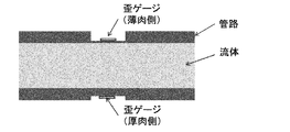
例えば、図6のように、内部を流体が流通する管路において、管壁に薄肉部を設け当該薄肉部に歪ゲージを貼付けその出力を計測すると、薄肉部の肉厚を薄くした場合には内圧に加えて流量の影響が歪ゲージにより計測されることから、管壁に設けた複数の肉厚の異なる薄肉部に歪ゲージを貼付け、その出力差から管路内の流量を計測する流量計を提供するものであって、出力差と流量の関係を表す校正式は予め校正により求めておく。
The flow meter of
The flow meter of
For example, as shown in FIG. 6, in a pipeline through which fluid flows, when a thin wall is provided on the pipe wall and a strain gauge is attached to the thin wall and the output is measured, the thickness of the thin wall is reduced. Since the effect of the flow rate is measured by the strain gauge in addition to the internal pressure, a strain gauge is attached to the thin wall parts with different thicknesses provided on the tube wall, and the flow meter measures the flow rate in the pipeline from the output difference The calibration formula representing the relationship between the output difference and the flow rate is obtained in advance by calibration.
説明をわかりやすくするために、実測例に則して測定原理を説明すると、図7に示すように、直管は、内径12mmφ、肉厚1mmで、長さ40mmである。直管の材質には、生体適合性に優れたチタン合金を使用している。歪計測部として両端から20mmの位置に局所的な歪が生じやすいよう、直径6mmの薄肉加工を施し2箇所の薄肉部を設けた。歪計測部としての2箇所の薄肉部の薄い側の肉厚は0.11mm、厚い側の肉厚は0.18mmである。歪計測部には、ゲージ長0.2mmの歪ゲージが2枚、2アクティブゲージ法で貼付けられており、管路内の流体によって管に生じる管の周方向の歪を計測している。
図8に示すように、直管を用いた流量計を組み込んで実測した流体回路は、血液ポンプ、リザーバ、流路抵抗、直管から構成される体外循環系を模擬した閉回路である。閉回路内の圧力は直管の入り口と出口で、圧力計を用いて計測した。閉回路内の流量は血液ポンプ出口で、超音波流量計を用いて計測した。
上記チタン合金製の直管を用いて静圧計測試験を実施した。静圧計測試験では、まず回路を閉鎖し、ポンプの回転数を増加させることで、流量0[L/min]を維持したまま、回路内の静圧を0から150[mmHg]まで、25[mmHg]刻みで増加させた。静圧計測試験の結果を図9に示す。図9のグラフにおいて、横軸が圧力計で計測した圧力[mmHg]、縦軸が歪ゲージ出力[μST]であり、●のプロットが肉厚の薄い方の薄肉部(薄肉側:肉厚0.11mm)の歪ゲージの出力で、▲のプロットが肉厚の厚い方の薄肉部(厚肉側:肉厚0.18mm)の歪ゲージの出力である。
歪ゲージから計測された歪と圧力計で計測された静圧の関係の2つの校正式を得る。
PS=αA×ε0.11S+βA (1A)
PS=αB×ε0.18S+βB (1B)
ここで、PSは静圧を示しており、ε0.11Sとε0.18Sはそれぞれ静圧による薄肉側の薄肉部の歪と厚肉側の薄肉部の歪を示している。αA、βA、αB、βBは、本静圧計測試験で決まる定数である。
To make the explanation easy to understand, the measurement principle will be described in accordance with an actual measurement example. As shown in FIG. 7, the straight pipe has an inner diameter of 12 mmφ, a wall thickness of 1 mm, and a length of 40 mm. The straight pipe is made of titanium alloy with excellent biocompatibility. As a strain measurement part, thin processing of 6 mm in diameter was performed so that local strain was easily generated at
As shown in FIG. 8, the fluid circuit actually measured by incorporating a flow meter using a straight pipe is a closed circuit simulating an extracorporeal circulation system including a blood pump, a reservoir, a flow path resistance, and a straight pipe. The pressure in the closed circuit was measured using a pressure gauge at the inlet and outlet of the straight pipe. The flow rate in the closed circuit was measured using an ultrasonic flow meter at the blood pump outlet.
A static pressure measurement test was carried out using the straight pipe made of the titanium alloy. In the static pressure measurement test, first, the circuit is closed and the number of rotations of the pump is increased, so that the static pressure in the circuit is reduced from 0 to 150 [mmHg] to 25 [ mmHg] in increments. The results of the static pressure measurement test are shown in FIG. In the graph of FIG. 9, the horizontal axis is the pressure [mmHg] measured by the pressure gauge, the vertical axis is the strain gauge output [μST], and the ● plot is the thinner part (thin side: thickness 0) .11 mm) of the strain gauge output, and the plot of ▲ is the output of the strain gauge of the thinner part (thick side: 0.18 mm thickness) of the thicker one.
Two calibration formulas are obtained for the relationship between the strain measured from the strain gauge and the static pressure measured by the pressure gauge.
P S = α A × ε 0.11S + β A (1A)
P S = α B × ε 0.18S + β B (1B)
Here, P S represents the strain of the thin portion of the strain and the thick side of the thin portion of the thin wall side by it and, ε 0.11S and epsilon 0.18S each static pressure indicates static pressure. α A , β A , α B and β B are constants determined by the static pressure measurement test.
次に、流体回路に流体を流し、流量を変えて計測試験を行う。
図10に、流体を流した時の薄肉側の薄肉部の歪ゲージの出力を、上記式(1A)を元に圧力換算した結果を示す。図10において、横軸は圧力計で計測した圧力[mmHg]、縦軸は圧力換算値[mmHg]であり、各プロットは、■:1[L/min]、◆:2[L/min]、▲:3[L/min]、×:4[L/min]、*:5[L/min]を示しており、●は流量0[L/min]の場合(横軸の圧力計で計測した圧力と縦軸の圧力換算値とが同じとなる)をReferenceとして…線で示してある。
図10より、流体が流れると、薄肉側の薄肉部の歪ゲージ出力から算出した圧力換算値は流量の増加に応じて増加することがわかった。そのため、流量により増加した薄肉部の圧力をPDとすると流量発生時の圧力PAは以下の式(2)のようになる。
PA=PS+PD=αA×(ε0.11S+ε0.11D)+βA (2)
ここで、ε0.11Dは流量により増加した薄肉側の薄肉部の歪を示す。
図11に、流体を流した時の厚肉側の薄肉部の歪ゲージの出力を、上記式(1B)を元に圧力換算した結果を示す。図11において、横軸は圧力計で計測した圧力[mmHg]、縦軸は圧力換算値[mmHg]であり、各プロット印は図10と同様に流量の違いを区別して表したものであって、■:1[L/min]、◆:2[L/min]、▲:3[L/min]、×:4[L/min]、*:5[L/min]を示しており、●は流量0[L/min]の場合(横軸の圧力計で計測した圧力と縦軸の圧力換算値が同じとなる)をReferenceとして…線で示してある。
図11より、流体が流れると、厚肉側の薄肉部の歪ゲージ出力から算出した圧力換算値は流量の増加に応じて減少することがわかった。そのため、流量により減少した薄肉部の圧力をPDBとすると流量発生時の圧力PBは以下の式(3)のようになる。
PB=PS−PDB=αB×(ε0.18S−ε0.18D)+βB (3)
ここで、ε0.18Dは流量により減少した厚肉側の薄肉部の歪を示す。
なお、図10及び図11に示すような流量の影響が発現するには、通常の圧力計のダイヤフラムに用いる肉厚(0.5mm程度)より薄肉部を薄くすることが望ましく、特に薄肉側の薄肉部の肉厚は極力薄くすることが好ましい。
Next, a measurement test is performed by flowing a fluid through the fluid circuit and changing the flow rate.
FIG. 10 shows the result of pressure-converting the output of the strain gauge at the thin-walled portion on the thin-walled side when the fluid is flowed based on the above formula (1A). In FIG. 10, the horizontal axis is the pressure [mmHg] measured with a pressure gauge, the vertical axis is the pressure conversion value [mmHg], and the plots are as follows: ■: 1 [L / min], ◆: 2 [L / min] , ▲: 3 [L / min], x: 4 [L / min], *: 5 [L / min], ● ● when the flow rate is 0 [L / min] The measured pressure and the pressure conversion value on the vertical axis are the same).
From FIG. 10, it was found that when the fluid flows, the pressure conversion value calculated from the strain gauge output of the thin portion on the thin side increases as the flow rate increases. Therefore, the pressure P A in the pressure of the thin portion that is increased by the flow rate and P D at flow generator is represented by the following formula (2).
P A = P S + P D = α A × (ε 0.11S + ε 0.11D ) + β A (2)
Here, ε 0.11D indicates the distortion of the thin portion on the thin side increased by the flow rate.
FIG. 11 shows the result of pressure-converting the output of the strain gauge on the thin-walled portion on the thick-wall side when a fluid is flowed based on the above equation (1B). In FIG. 11, the horizontal axis represents the pressure [mmHg] measured with a pressure gauge, the vertical axis represents the pressure conversion value [mmHg], and each plot mark represents the difference in flow rate as in FIG. , ■: 1 [L / min], ◆: 2 [L / min], ▲: 3 [L / min], x: 4 [L / min], *: 5 [L / min] ● indicates a reference when the flow rate is 0 [L / min] (the pressure measured by the pressure gauge on the horizontal axis is the same as the pressure converted value on the vertical axis).
From FIG. 11, it was found that when the fluid flows, the pressure conversion value calculated from the strain gauge output of the thin portion on the thick side decreases as the flow rate increases. Therefore, if the pressure of the thin wall portion reduced by the flow rate is P DB , the pressure P B when the flow rate is generated is expressed by the following equation (3).
P B = P S −P DB = α B × (ε 0.18S −ε 0.18D ) + β B (3)
Here, ε 0.18D indicates the distortion of the thin portion on the thick side reduced by the flow rate.
In order to exert the influence of the flow rate as shown in FIG. 10 and FIG. 11, it is desirable to make the thin part thinner than the thickness (about 0.5 mm) used for the diaphragm of a normal pressure gauge. It is preferable to reduce the thickness of the thin portion as much as possible.
そこで、流体を流した時の薄肉側の薄肉部の歪ゲージの出力の圧力換算値から厚肉側の薄肉部の歪ゲージの出力の圧力換算値を引き算した両者の差分である差圧ΔPは、上記式(2)と式(3)から以下の式(4)となる。
PA−PB=PDA+PDB
=αA×(ε0.11S+ε0.11D)−αB×(ε0.18S−ε0.18D)+C (4)
ここで、Cは定数である。さらに、薄肉側の薄肉部の歪ゲージと厚肉側の薄肉部の歪ゲージの出力をそれぞれε0.11とε0.18として整理すると上記式(4)は以下の式(5)のようになる。
ΔP=PA−PB=αA×ε0.11−αB×ε0.18+C (5)
本式より2つの歪ゲージの差分を取ることで圧力補償が行われ、流量の項のみ残る。したがって、2つの歪ゲージの差分と流量の関係を予め校正して校正式(例えば、後述する図12に示すグラフ参照)として求めておけば、2つの歪ゲージの差分を計測して校正式に当てはめることにより流量を得ることができる。
Therefore, the differential pressure ΔP, which is the difference between the subtraction of the pressure conversion value of the output of the strain gauge on the thin wall side from the pressure conversion value of the output of the strain gauge on the thin wall side when the fluid is flowed, is From the above equations (2) and (3), the following equation (4) is obtained.
P A -P B = P DA + P DB
= Α A × (ε 0.11S + ε 0.11D ) −α B × (ε 0.18S −ε 0.18D ) + C (4)
Here, C is a constant. Further, when the outputs of the thin-walled strain gauge and the thick-walled strain gauge are arranged as ε 0.11 and ε 0.18 , respectively, the above equation (4) becomes the following equation (5).
ΔP = P A −P B = α A × ε 0.11 −α B × ε 0.18 + C (5)
By taking the difference between the two strain gauges from this equation, pressure compensation is performed and only the flow rate term remains. Therefore, if the relationship between the difference between the two strain gauges and the flow rate is previously calibrated and obtained as a calibration formula (for example, see the graph shown in FIG. 12 described later), the difference between the two strain gauges is measured and the calibration formula is obtained. The flow rate can be obtained by fitting.
図12には、この関係を利用して流量Flowを得るため、回路抵抗を変えて管路内圧を25[mmHg]から150[mmHg]に変化させ、ポンプで流量を変化させた時の測定結果を示す。図9において、縦軸は薄肉側の薄肉部の歪ゲージの出力の圧力換算値から厚肉側の薄肉部の歪ゲージの出力の圧力換算値を引き算した差分(ΔP)であり、横軸は市販の流量計で計測した流量[L/min]であり、プロット印は管路内圧●:25[mmHg]、■:50[mmHg]、◆:75[mmHg]、▲:100[mmHg]、×:125[mmHg]、*:150[mmHg]を示している。図9のグラフから、薄肉側の薄肉部の歪ゲージの出力の圧力換算値から厚肉側の薄肉部の歪ゲージの出力の圧力換算値を引き算した差分(ΔP)と流量とが回路抵抗の大小にかかわらず一対一に対応していることが確認でき、図12のグラフを予め校正試験を行うことで校正式として求めておけば、薄肉側の薄肉部の歪ゲージの出力の圧力換算値から厚肉側の薄肉部の歪ゲージの出力の圧力換算値を引き算した差分の値を校正式に当てはめて流量を求めることができる。
図12のグラフを記憶手段等に記憶させておけばそのまま校正式として用いることもできるが、図12のグラフを近似式で表し、近似式を校正式として用いて流量Flowを算出することもできる。
In FIG. 12, in order to obtain the flow rate Flow using this relationship, the circuit resistance is changed to change the pipe internal pressure from 25 [mmHg] to 150 [mmHg], and the measurement result when the flow rate is changed by the pump. Indicates. In FIG. 9, the vertical axis represents the difference (ΔP) obtained by subtracting the pressure converted value of the output of the strain gauge on the thin wall side from the pressure converted value of the output of the strain gauge on the thin wall side, and the horizontal axis represents It is the flow rate [L / min] measured with a commercially available flow meter, and the plot marks are the pipe internal pressure ●: 25 [mmHg], ■: 50 [mmHg], ◆: 75 [mmHg], ▲: 100 [mmHg], X: 125 [mmHg], *: 150 [mmHg]. From the graph of FIG. 9, the difference (ΔP) obtained by subtracting the pressure converted value of the output of the strain gauge on the thin wall side from the pressure converted value of the output of the strain gauge on the thin wall side and the flow rate is the circuit resistance. Regardless of the size, one-to-one correspondence can be confirmed, and if the graph of FIG. 12 is obtained as a calibration formula by performing a calibration test in advance, the pressure conversion value of the strain gauge output of the thin part on the thin side The flow rate can be obtained by applying the difference value obtained by subtracting the pressure converted value of the output of the strain gauge at the thin wall portion on the thick wall side to the calibration equation.
If the graph of FIG. 12 is stored in the storage means or the like, it can be used as a calibration formula as it is, but the graph of FIG. 12 can be expressed by an approximate formula and the flow rate Flow can be calculated using the approximate formula as a calibration formula. .
重症心不全患者の心機能補助や、心臓移植までの橋渡しとして、体内埋込型人工心臓が用いられている。体内埋込型人工心臓の駆動状態や、人工心臓を適用された患者の生理学的な情報を得るため、人工心臓の血流量を計測することは、患者の生存率やQOL(Quality of Life)の向上に重要である。現在、人工心臓の血流量を計測する方法として、流量推定法や、超音波流量計などの市販流量計を使用する方法がある。流量推定法は、人工心臓の消費電力と回転数から流量を推定する方法である。遠心型人工心臓の消費電力は流量に対して相関があるため、流量推定法が適用可能であるが、人工心臓内に血栓が生じた場合などは流量推定が困難となる。軸流型人工心臓において、消費電力は流量に対して相関が無いため、流量推定は困難である。市販流量計は、超音波流量計や電磁流量計がある。しかし、これら市販流量計は計測原理が複雑であるため小型化が困難であり、人工心臓と共に体内に埋め込むことは容易ではない。そのため、人工心臓の種類を問わず使用可能で、小型化が可能な血流量計が必要である。これまで、小型でシンプルな計測方式の流量計として曲がり管を用いた質量流量計を提案してきたが、曲がり管を用いる必要があった。本発明者等は、先に特許文献6の直管を用いた流量計も提案したが、薄肉側の薄肉部となる計測部は静圧と流量の影響が現れるほど極薄肉にする必要があり、薄肉であればあるほど感度が上がるが加工が難しくなるという問題があった。
そこで、本発明が解決しようとする課題は、静圧と流量の影響が現れる薄肉部について改善工夫することにある。
An implantable artificial heart is used as a support for cardiac function in patients with severe heart failure and as a bridge to heart transplantation. Measuring the blood flow volume of the artificial heart to obtain the driving status of the implantable artificial heart and the physiological information of the patient to whom the artificial heart is applied is a measure of the patient's survival rate and QOL (Quality of Life). It is important for improvement. Currently, methods for measuring the blood flow of an artificial heart include a flow rate estimation method and a method using a commercially available flow meter such as an ultrasonic flow meter. The flow rate estimation method is a method for estimating the flow rate from the power consumption and the rotation speed of the artificial heart. Since the power consumption of the centrifugal artificial heart has a correlation with the flow rate, the flow rate estimation method can be applied. However, when a thrombus occurs in the artificial heart, the flow rate estimation becomes difficult. In an axial flow type artificial heart, power consumption has no correlation with the flow rate, and therefore it is difficult to estimate the flow rate. Commercially available flow meters include ultrasonic flow meters and electromagnetic flow meters. However, these commercially available flow meters are difficult to miniaturize because of the complicated measurement principle, and it is not easy to implant them together with an artificial heart. Therefore, there is a need for a blood flow meter that can be used regardless of the type of artificial heart and can be miniaturized. So far, mass flowmeters using bent tubes have been proposed as small and simple flowmeters, but it has been necessary to use bent tubes. The present inventors have previously proposed a flow meter using a straight pipe of
Therefore, the problem to be solved by the present invention is to improve the thin portion where the influence of static pressure and flow rate appears.
上記課題を解決するために、本発明の流量計は、内部を流体が流通する管路と、前記管路の直管部の管壁に設けた少なくとも2つの薄肉部と、前記薄肉部に貼付けた歪ゲージと、前記歪ゲージの出力を処理する演算処理装置を備えた管路内の流量を計測する流量計であって、片側の薄肉部の管路内側の流路内に微小突起部が設けられており、前記演算処理手段には予め校正試験により求めた微小突起を有する薄肉部に貼り付けた歪ゲージと、微小突起を持たない薄肉部に貼り付けた歪ゲージの出力差と流量の関係を表す校正式が記憶されており、前記校正式を用いて前記出力差から流量を求めることを特徴とする。
また、本発明は上記流量計において、前記微小突起を有する薄肉部と前記微小突起を持たない薄肉部は前記直管部の同一断面に設けたことを特徴とする。
また、本発明は上記流量計において、前記微小突起を有する薄肉部と前記微小突起を持たない薄肉部以外に厚肉の薄肉部を設け、当該厚肉の薄肉部に貼付けた補償用の歪ゲージの出力により外乱の影響を補償することを特徴とする。
また、本発明は上記流量計において、前記校正式を用いて求めた流量と前記薄肉部に貼付けた歪ゲージの出力から静圧を計測することを特徴とする。
また、本発明は上記流量計において、前記計測した静圧を流量で除算することにより管路抵抗を計測することを特徴とする。
また、本発明は上記流量計において、前記校正式は、低流量域と高流量域で異なる近似式を用いて表したことを特徴とする。
また、本発明は、内部を流体が流通する管路の直管部の管壁に少なくとも2つの肉厚の異なる薄肉部を設けて当該薄肉部に歪ゲージを貼付け、片側の薄肉部は管路内側に流路に微小突起部が設けられており、予め校正試験により微小突起を有する薄肉部に貼り付けた歪ゲージと、微小突起を持たない薄肉部に貼り付けた歪ゲージの出力差と流量の関係を表す校正式を求めておき、計測した微小突起を有する薄肉部に貼り付けた歪ゲージと、微小突起を持たない薄肉部に貼り付けた歪ゲージの出力差から、前記校正式を用いて管路内の流量を求める流量計測方法である。
In order to solve the above-mentioned problems, the flowmeter of the present invention is affixed to a pipe line through which a fluid flows, at least two thin parts provided on a pipe wall of a straight pipe part of the pipe, and the thin part A flow meter for measuring the flow rate in the pipe line provided with a strain gauge and an arithmetic processing unit for processing the output of the strain gauge, wherein a minute protrusion is formed in the flow path inside the pipe line of the thin part on one side. The arithmetic processing means includes an output difference and a flow rate between a strain gauge attached to a thin portion having a fine protrusion obtained in advance by a calibration test and a strain gauge attached to a thin portion having no fine protrusion. A calibration equation representing the relationship is stored, and the flow rate is obtained from the output difference using the calibration equation.
Further, the present invention is characterized in that, in the flowmeter, the thin portion having the fine protrusion and the thin portion not having the fine protrusion are provided in the same cross section of the straight pipe portion.
Further, the present invention provides the above-described flowmeter, wherein the compensation strain gauge is provided with a thick thin portion in addition to the thin portion having the fine protrusion and the thin portion not having the fine protrusion, and is attached to the thin portion. The effect of disturbance is compensated by the output of.
In the above flow meter, the present invention is characterized in that a static pressure is measured from a flow rate obtained by using the calibration formula and an output of a strain gauge attached to the thin portion.
In the above flow meter, the present invention is characterized in that the pipe resistance is measured by dividing the measured static pressure by the flow rate.
Further, the present invention is characterized in that, in the above flow meter, the calibration formula is expressed using different approximate formulas in a low flow rate region and a high flow rate region.
Further, the present invention provides at least two thin wall portions having different thicknesses on a pipe wall of a straight pipe portion of a pipe through which a fluid flows, and a strain gauge is attached to the thin wall portion. A microprojection is provided in the flow path on the inside, and the output difference and flow rate between the strain gauge attached in advance to the thin part with microprotrusions and the strain gauge attached to the thin part without microprotrusions by a calibration test. A calibration equation that expresses the relationship between the strain gauge and the strain gage applied to the thin portion with no microprotrusions and the output difference between the strain gauge attached to the thin portion without microprotrusions is used. This is a flow rate measurement method for obtaining the flow rate in the pipeline.
本発明では曲がり管を用いずに直管のみで流量計測が可能となり、そのため、極めてコンパクトな流量計を実現することができ、また、片側の薄肉部の管路内側の流路内に微小突起部を設けることにより、静圧と流量の影響が大きく現れるため、従来の特許文献6のように極薄肉加工で感度を上げることを要しない。
また、流量計測の結果と薄肉部に貼付けた歪ゲージの出力から管路内部の静圧を計測することが可能である。
また、静圧と流量計の計測結果から、管路内抵抗(=静圧/流量)を求めることが出来る。そのため、管路の詰まり具合や狭窄などの管路異常を検知することができる。
また、本発明では、曲がり管を用いずに直管のみで管路内の流量を計測可能なシンプルな流量計測方法を実現することができる。
In the present invention, it is possible to measure the flow rate with only a straight pipe without using a bent pipe, and therefore, an extremely compact flow meter can be realized, and a minute protrusion is formed in the flow path inside the pipe line of the thin part on one side. Since the influence of the static pressure and the flow rate appears greatly by providing the portion, it is not necessary to increase the sensitivity by ultra-thin processing as in the
Moreover, it is possible to measure the static pressure inside the pipe line from the result of the flow rate measurement and the output of the strain gauge attached to the thin wall portion.
Further, the resistance in the pipe line (= static pressure / flow rate) can be obtained from the measurement result of the static pressure and the flow meter. For this reason, it is possible to detect abnormalities in the pipeline such as clogging or narrowing of the pipeline.
In the present invention, it is possible to realize a simple flow rate measuring method capable of measuring the flow rate in the pipe line with only a straight pipe without using a bent pipe.
本発明者等が先に提案した特許文献6では、薄肉側の薄肉部をより極薄にすれば感度を上げられるが、極薄にしようとすればするほど薄肉加工が難しくなり、また極薄部での破損の恐れ等も考慮しなければならなかった。そこで、本発明者等の鋭意研究の結果、極薄化に代えて、片側の薄肉部の管路内側の流路内に微小突起部を設けることにより、静圧と流量の影響が大きく現れることをつきとめ、内部を流体が流通する管路において、直管部の管壁に設けた少なくとも2つの薄肉部と、前記薄肉部に貼付けた歪ゲージと、前記歪ゲージの出力を処理する演算処理装置を備えた管路内の流量を計測する流量計において、片側の薄肉部の管路内側の流路内に微小突起部を設け、前記演算処理手段には予め校正試験により求めた微小突起を有する薄肉部に貼り付けた歪ゲージと、微小突起を持たない薄肉部に貼り付けた歪ゲージの出力差と流量の関係を表す校正式が記憶されており、前記校正式を用いて前記出力差から管路内の流量を求める流量計を開発した。
In
本発明の一実施例である直管式流量計の断面図を図1に示す。図において、流路内に微小突起を有する流量計測用の薄肉部と微小突起を持たない静圧補償用の薄肉部を持つ。この2箇所の計測部には、歪ゲージを貼り付け、各計測部に生じる周方向の歪を計測する。流量は、2箇所の薄肉部の歪ゲージの出力差より求めることができる。
このことは、上記段落0003〜段落0006に記載した本発明者等による特許文献6の測定原理の説明を参照すれば、当該説明中の式(1)〜(5)は、εの添え字の「0.11」と「0.18」をそれぞれ本願発明の『微小突起を有する薄肉部』と『微小突起を持たない薄肉部』と読み替えるだけで式(1)〜(5)がそのまま成り立つことがわかる。したがって、『微小突起を有する薄肉部』と『微小突起を持たない薄肉部』の2つの歪ゲージの差分と流量の関係を予め校正して校正式を求めておけば、2つの歪ゲージの差分を計測して校正式に当てはめることにより流量を得ることができる。
A cross-sectional view of a straight pipe type flow meter which is an embodiment of the present invention is shown in FIG. In the figure, there are a thin portion for flow rate measurement having fine protrusions in the flow path and a thin portion for static pressure compensation having no fine protrusions. Strain gauges are affixed to the two measurement units, and the circumferential strain generated in each measurement unit is measured. The flow rate can be obtained from the output difference between the strain gauges at the two thin portions.
With reference to the description of the measurement principle of
図2は、本発明の直管式流量計の作製例の主要部を説明した図であり、図3は本発明の特徴である微小突起を管内面側から写したものである。作製例では、流量計プローブとして、人工心臓の種類を問わず使用可能で、小型化が可能なチタン合金製の直管を用いた。直管の長さは40mmであり、内径、外径はそれぞれ12mm、14mmである。本流量計は、流量計測部と静圧補償部として、両端から20mmの管路外壁の両側に、直径6mmの肉厚の異なる2ヶ所の薄肉部を設けた。2ヶ所の薄肉部は、流路内に微小突起を有する流量計測用の肉厚0.01mmの薄肉部と微小突起を持たない静圧補償用の肉厚0.75mmの薄肉部とした。各計測部には、歪ゲージを貼り付け、計測部に生じる周方向の歪を計測する。
流量計測部では、静圧と流量によって歪計測部に生じる歪を計測し、静圧補償部では静圧によって歪計測部に生じる歪を計測する。流量は、流量計測部と静圧補償部の歪ゲージの出力差から計測する。
FIG. 2 is a diagram for explaining a main part of a production example of a straight pipe type flow meter according to the present invention, and FIG. In the production example, a straight tube made of a titanium alloy that can be used regardless of the type of the artificial heart and can be reduced in size is used as the flowmeter probe. The length of the straight pipe is 40 mm, and the inner diameter and the outer diameter are 12 mm and 14 mm, respectively. This flow meter was provided with two thin portions having a diameter of 6 mm and different thicknesses on both sides of a pipe
The flow rate measuring unit measures strain generated in the strain measuring unit by the static pressure and the flow rate, and the static pressure compensating unit measures strain generated in the strain measuring unit by the static pressure. The flow rate is measured from the output difference between the strain gauges of the flow rate measurement unit and the static pressure compensation unit.
本発明の流量計の上記作製例について評価試験を行うための、図4の体循環系を模擬した模擬循環回路を構築した。模擬循環回路は、血液ポンプ、塩化ビニル製のチューブ、血液リザーバ、アクリルパイプ、本発明の直管式流量計から構成されている。模擬循環回路中の圧力および流量は、回路中に設置した流路抵抗により調整される。作動流体には水道水を用い、温度は室温とした。血液ポンプ出口の流れは非常に乱れていることが予想されたため、血液ポンプと直管式流量計の間は助走区間とし、直管式流量計の内径の約80倍の距離を持つ1mのアクリルパイプで接続した。直管式流量計に貼り付けた歪ゲージで計測された歪は、直流型歪増幅器で約20,000倍に増幅した。各計測器で計測されたデータはADカードによりディジタル化し、サンプリング周波数100Hzで計測用パソコンに取り込まれる。評価試験では、流量をポンプの回転数により流量を調整し、市販の超音波式流量計と計測精度を比較した。 A simulated circulation circuit simulating the systemic circulation system of FIG. 4 was constructed to perform an evaluation test on the above-described production example of the flowmeter of the present invention. The simulated circulation circuit is composed of a blood pump, a tube made of vinyl chloride, a blood reservoir, an acrylic pipe, and the straight pipe type flow meter of the present invention. The pressure and flow rate in the simulated circulation circuit are adjusted by the channel resistance installed in the circuit. Tap water was used as the working fluid and the temperature was room temperature. The flow at the outlet of the blood pump was expected to be very turbulent, so there was a run-up section between the blood pump and the straight pipe flow meter, and a 1 m acrylic with a distance of about 80 times the inner diameter of the straight pipe flow meter. Connected with a pipe. The strain measured with the strain gauge attached to the straight pipe flowmeter was amplified about 20,000 times with a DC strain amplifier. Data measured by each measuring instrument is digitized by an AD card and is taken into a measuring personal computer at a sampling frequency of 100 Hz. In the evaluation test, the flow rate was adjusted by the number of rotations of the pump, and the measurement accuracy was compared with a commercially available ultrasonic flow meter.
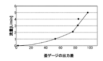
評価試験の結果を図5に示す。グラフの横軸は、直管式流量計の2箇所の歪ゲージの出力差を示し、縦軸は市販の超音波式流量計で計測された流量を示す。歪ゲージの出力差と流量の関係は、流量2L/minを境に変化した。そのため、流量算出のため、流量2L/min前後で2つの校正式を作成した。直管式流量計の校正式から求められる流量と市販の超音波式流量計で計測された流量を比較した結果、平均計測誤差は0.5L/min以内となることがわかった。
微小突起部を設けることで流量計測が可能となった原因として、微小突起部周辺の流速の変化が考えられる。流量が発生したときに生じる動圧は、流速の変動により変わる。そのため、本微小突起部が設けられた歪計測部で、流速の変動で生じる動圧により、歪計測部の歪量が増加したと考えられた。本発明により、曲がり管を用いることなく直管のみで流量計測が可能となる。そのため、人工心臓の種類を問わず使用可能で、小型化が可能な血流量計を実現することが出来ると考える。
The result of the evaluation test is shown in FIG. The horizontal axis of the graph indicates the output difference between two strain gauges of the straight pipe flow meter, and the vertical axis indicates the flow rate measured by a commercially available ultrasonic flow meter. The relationship between the strain gauge output difference and the flow rate changed at a flow rate of 2 L / min. Therefore, in order to calculate the flow rate, two calibration formulas were created at a flow rate of about 2 L / min. As a result of comparing the flow rate obtained from the calibration formula of the straight pipe type flow meter with the flow rate measured with a commercially available ultrasonic flow meter, it was found that the average measurement error was within 0.5 L / min.
A possible change in the flow velocity around the microprojection can be considered as a cause of the flow rate measurement by providing the microprojection. The dynamic pressure generated when the flow rate is generated varies depending on the fluctuation of the flow velocity. For this reason, it was considered that the strain amount of the strain measurement unit increased due to the dynamic pressure generated by the fluctuation of the flow velocity in the strain measurement unit provided with the minute projections. According to the present invention, it is possible to measure the flow rate using only a straight pipe without using a bent pipe. Therefore, it is considered that a blood flow meter that can be used regardless of the type of artificial heart and can be miniaturized can be realized.
本発明の流量計は、小型・軽量な圧流量計での圧力と流量計測が必要な分野。例えば、人工心臓などの医療用圧流量計や、石油、石油化学、化学などのプラントの配管を流れる流体やガス、ビンの洗浄水、ウェハや基板の洗浄液、薬剤などの流量計測計として利用することができる。 The flowmeter of the present invention is a field that requires pressure and flow measurement with a compact and lightweight pressure flowmeter. For example, it is used as a flow meter for medical pressure flowmeters such as artificial hearts, fluids and gases flowing through the piping of plants such as petroleum, petrochemicals, and chemicals, cleaning water for bottles, cleaning liquids for wafers and substrates, and chemicals. be able to.
Claims (6)
前記薄肉部のうちの一方の第1薄肉部には前記管路内側の流路内に微小突起が設けられており、前記演算処理装置には予め校正試験により求めた前記第1薄肉部に貼り付けた前記歪ゲージ及び前記薄肉部のうちの他方の第2薄肉部に貼り付けた前記歪ゲージの出力差と流量の関係を表す校正式が記憶されており、前記校正式を用いて前記出力差から流量を求めることを特徴とする流量計。 Processes the pipe through which fluid flows, at least two thin parts provided on the same cross-section pipe wall of the straight pipe part of the pipe, the strain gauge affixed to the thin part, and the output of the strain gauge A flow meter for measuring a flow rate in a pipe line equipped with an arithmetic processing unit,
Said one first thin portion of the thin portion is provided small collision outs in the conduit inside the flow path, the first thin portion obtained by the calibration test in advance to the arithmetic processing unit calibration equation representing the pasted the strain gauge and the other second output difference of the strain gauge was attached to the thin portion and the flow rate of the relationships among the thin portion are stored, said using said calibration equation A flow meter characterized by obtaining a flow rate from an output difference.
前記第1薄肉部に貼り付けた前記歪ゲージ及び前記第2薄肉部に貼り付けた前記歪ゲージの出力差から、前記校正式を用いて前記管路内の流量を求めることを特徴とする流量計測方法。 The strain gauge sticking to the thin portion of the inner portion provided with at least two thin-walled portion in the tube wall of the same section of the straight pipe portion of the pipe in which the fluid flows, the pre Me calibration test of the thin portion one of pasted to the first thin portion having a small protrusion of the strain gauge and calibration equation representing the other of the second output difference of the strain gauge was attached to the thin portion and the flow rate of the relationships among the thin portion Asking
Flow rate and obtains the flow rate of the the output difference between the strain gauge and the second said strain gauge affixed to the thin portion adhered to the first thin portion, the conduit using the calibration equation Measurement method.
Priority Applications (1)
| Application Number | Priority Date | Filing Date | Title |
|---|---|---|---|
| JP2015172675A JP6587129B2 (en) | 2015-09-02 | 2015-09-02 | Flowmeter |
Applications Claiming Priority (1)
| Application Number | Priority Date | Filing Date | Title |
|---|---|---|---|
| JP2015172675A JP6587129B2 (en) | 2015-09-02 | 2015-09-02 | Flowmeter |
Publications (2)
| Publication Number | Publication Date |
|---|---|
| JP2017049125A JP2017049125A (en) | 2017-03-09 |
| JP6587129B2 true JP6587129B2 (en) | 2019-10-09 |
Family
ID=58278773
Family Applications (1)
| Application Number | Title | Priority Date | Filing Date |
|---|---|---|---|
| JP2015172675A Active JP6587129B2 (en) | 2015-09-02 | 2015-09-02 | Flowmeter |
Country Status (1)
| Country | Link |
|---|---|
| JP (1) | JP6587129B2 (en) |
Family Cites Families (7)
| Publication number | Priority date | Publication date | Assignee | Title |
|---|---|---|---|---|
| JPH0677236U (en) * | 1993-04-08 | 1994-10-28 | 大日本スクリーン製造株式会社 | Substrate processing liquid flow rate measuring device |
| JP3171017B2 (en) * | 1994-08-22 | 2001-05-28 | 横河電機株式会社 | Flowmeter |
| JPH08110279A (en) * | 1994-10-11 | 1996-04-30 | Mitsubishi Heavy Ind Ltd | In-cylinder pressure sensor |
| JPH10132676A (en) * | 1996-11-01 | 1998-05-22 | Mitsubishi Heavy Ind Ltd | Dynamic pressure measuring apparatus in piping |
| GB2335494A (en) * | 1998-03-16 | 1999-09-22 | Abb Seatec Ltd | Venturi Flow Meter |
| EP2458358B1 (en) * | 2010-11-29 | 2017-09-27 | Corning Incorporated | In-line contactless pressure sensors and methods of measuring pressure |
| JP6202327B2 (en) * | 2013-12-11 | 2017-09-27 | 国立研究開発法人産業技術総合研究所 | Mass flow meter and static pressure measurement method |
-
2015
- 2015-09-02 JP JP2015172675A patent/JP6587129B2/en active Active
Also Published As
| Publication number | Publication date |
|---|---|
| JP2017049125A (en) | 2017-03-09 |
Similar Documents
| Publication | Publication Date | Title |
|---|---|---|
| US7730793B2 (en) | Venturi flow sensor | |
| JP5999725B2 (en) | Mass flow meter | |
| US20070193371A1 (en) | Mass flow meter | |
| CN109855691B (en) | Differential laminar flow measuring method and device | |
| JP6771254B2 (en) | Flow rate measuring device and flow rate measuring method | |
| JP4936392B2 (en) | Mass flow meter | |
| JP6587129B2 (en) | Flowmeter | |
| JP6418936B2 (en) | Flowmeter | |
| WO2017009668A1 (en) | Fluid delivery apparatus | |
| CN207147558U (en) | A kind of binary channels wide-range than flowmeter | |
| JP2010066184A (en) | Mass flowmeter | |
| JP6202327B2 (en) | Mass flow meter and static pressure measurement method | |
| JP2013142539A (en) | Mass flowmeter | |
| RU73600U1 (en) | SPIROMETER | |
| US20130096850A1 (en) | Method for determining an absolute flow rate of a volume or mass flow | |
| KR20060016557A (en) | Pitot tube and flow velocity measurement method and system using it | |
| JP2012159484A (en) | Mass flowmeter | |
| JP2975284B2 (en) | Viscosity measuring device | |
| JP6886675B2 (en) | Flow measuring device | |
| JP7020666B2 (en) | Gas flow rate calculation device, gas flow rate measurement system, gas flow rate calculation method and program | |
| CN214173502U (en) | Gas flowmeter calibrating device capable of dynamically compensating temperature change in real time | |
| JP2013040897A (en) | Pressure measuring device and pressure measuring method | |
| RU2641505C1 (en) | Information and measuring system for measurement of flow and quantity of gas | |
| Beaulieu et al. | A flowmeter for unsteady liquid flow measurements in total liquid ventilation | |
| RU28768U1 (en) | FLUID AND GAS FLOW METER |
Legal Events
| Date | Code | Title | Description |
|---|---|---|---|
| A621 | Written request for application examination |
Free format text: JAPANESE INTERMEDIATE CODE: A621 Effective date: 20180531 |
|
| A977 | Report on retrieval |
Free format text: JAPANESE INTERMEDIATE CODE: A971007 Effective date: 20190308 |
|
| A131 | Notification of reasons for refusal |
Free format text: JAPANESE INTERMEDIATE CODE: A131 Effective date: 20190319 |
|
| A601 | Written request for extension of time |
Free format text: JAPANESE INTERMEDIATE CODE: A601 Effective date: 20190515 |
|
| A521 | Request for written amendment filed |
Free format text: JAPANESE INTERMEDIATE CODE: A523 Effective date: 20190718 |
|
| TRDD | Decision of grant or rejection written | ||
| A01 | Written decision to grant a patent or to grant a registration (utility model) |
Free format text: JAPANESE INTERMEDIATE CODE: A01 Effective date: 20190828 |
|
| A61 | First payment of annual fees (during grant procedure) |
Free format text: JAPANESE INTERMEDIATE CODE: A61 Effective date: 20190829 |
|
| R150 | Certificate of patent or registration of utility model |
Ref document number: 6587129 Country of ref document: JP Free format text: JAPANESE INTERMEDIATE CODE: R150 |
|
| R250 | Receipt of annual fees |
Free format text: JAPANESE INTERMEDIATE CODE: R250 |
|
| R250 | Receipt of annual fees |
Free format text: JAPANESE INTERMEDIATE CODE: R250 |