JP6583965B2 - Series-parallel hydraulic hybrid structure - Google Patents
Series-parallel hydraulic hybrid structure Download PDFInfo
- Publication number
- JP6583965B2 JP6583965B2 JP2016541716A JP2016541716A JP6583965B2 JP 6583965 B2 JP6583965 B2 JP 6583965B2 JP 2016541716 A JP2016541716 A JP 2016541716A JP 2016541716 A JP2016541716 A JP 2016541716A JP 6583965 B2 JP6583965 B2 JP 6583965B2
- Authority
- JP
- Japan
- Prior art keywords
- hydraulic
- pressure accumulator
- valve
- hydraulic motor
- pump
- Prior art date
- Legal status (The legal status is an assumption and is not a legal conclusion. Google has not performed a legal analysis and makes no representation as to the accuracy of the status listed.)
- Expired - Fee Related
Links
Images


Classifications
-
- F—MECHANICAL ENGINEERING; LIGHTING; HEATING; WEAPONS; BLASTING
- F16—ENGINEERING ELEMENTS AND UNITS; GENERAL MEASURES FOR PRODUCING AND MAINTAINING EFFECTIVE FUNCTIONING OF MACHINES OR INSTALLATIONS; THERMAL INSULATION IN GENERAL
- F16H—GEARING
- F16H61/00—Control functions within control units of change-speed- or reversing-gearings for conveying rotary motion ; Control of exclusively fluid gearing, friction gearing, gearings with endless flexible members or other particular types of gearing
- F16H61/38—Control of exclusively fluid gearing
- F16H61/40—Control of exclusively fluid gearing hydrostatic
- F16H61/44—Control of exclusively fluid gearing hydrostatic with more than one pump or motor in operation
- F16H61/452—Selectively controlling multiple pumps or motors, e.g. switching between series or parallel
-
- B—PERFORMING OPERATIONS; TRANSPORTING
- B60—VEHICLES IN GENERAL
- B60K—ARRANGEMENT OR MOUNTING OF PROPULSION UNITS OR OF TRANSMISSIONS IN VEHICLES; ARRANGEMENT OR MOUNTING OF PLURAL DIVERSE PRIME-MOVERS IN VEHICLES; AUXILIARY DRIVES FOR VEHICLES; INSTRUMENTATION OR DASHBOARDS FOR VEHICLES; ARRANGEMENTS IN CONNECTION WITH COOLING, AIR INTAKE, GAS EXHAUST OR FUEL SUPPLY OF PROPULSION UNITS IN VEHICLES
- B60K6/00—Arrangement or mounting of plural diverse prime-movers for mutual or common propulsion, e.g. hybrid propulsion systems comprising electric motors and internal combustion engines ; Control systems therefor, i.e. systems controlling two or more prime movers, or controlling one of these prime movers and any of the transmission, drive or drive units Informative references: mechanical gearings with secondary electric drive F16H3/72; arrangements for handling mechanical energy structurally associated with the dynamo-electric machine H02K7/00; machines comprising structurally interrelated motor and generator parts H02K51/00; dynamo-electric machines not otherwise provided for in H02K see H02K99/00
- B60K6/08—Prime-movers comprising combustion engines and mechanical or fluid energy storing means
- B60K6/12—Prime-movers comprising combustion engines and mechanical or fluid energy storing means by means of a chargeable fluidic accumulator
-
- F—MECHANICAL ENGINEERING; LIGHTING; HEATING; WEAPONS; BLASTING
- F16—ENGINEERING ELEMENTS AND UNITS; GENERAL MEASURES FOR PRODUCING AND MAINTAINING EFFECTIVE FUNCTIONING OF MACHINES OR INSTALLATIONS; THERMAL INSULATION IN GENERAL
- F16H—GEARING
- F16H47/00—Combinations of mechanical gearing with fluid clutches or fluid gearing
- F16H47/02—Combinations of mechanical gearing with fluid clutches or fluid gearing the fluid gearing being of the volumetric type
-
- F—MECHANICAL ENGINEERING; LIGHTING; HEATING; WEAPONS; BLASTING
- F16—ENGINEERING ELEMENTS AND UNITS; GENERAL MEASURES FOR PRODUCING AND MAINTAINING EFFECTIVE FUNCTIONING OF MACHINES OR INSTALLATIONS; THERMAL INSULATION IN GENERAL
- F16H—GEARING
- F16H61/00—Control functions within control units of change-speed- or reversing-gearings for conveying rotary motion ; Control of exclusively fluid gearing, friction gearing, gearings with endless flexible members or other particular types of gearing
- F16H61/38—Control of exclusively fluid gearing
- F16H61/40—Control of exclusively fluid gearing hydrostatic
- F16H61/4078—Fluid exchange between hydrostatic circuits and external sources or consumers
- F16H61/4096—Fluid exchange between hydrostatic circuits and external sources or consumers with pressure accumulators
-
- F—MECHANICAL ENGINEERING; LIGHTING; HEATING; WEAPONS; BLASTING
- F16—ENGINEERING ELEMENTS AND UNITS; GENERAL MEASURES FOR PRODUCING AND MAINTAINING EFFECTIVE FUNCTIONING OF MACHINES OR INSTALLATIONS; THERMAL INSULATION IN GENERAL
- F16H—GEARING
- F16H47/00—Combinations of mechanical gearing with fluid clutches or fluid gearing
- F16H47/02—Combinations of mechanical gearing with fluid clutches or fluid gearing the fluid gearing being of the volumetric type
- F16H2047/025—Combinations of mechanical gearing with fluid clutches or fluid gearing the fluid gearing being of the volumetric type the fluid gearing comprising a plurality of pumps or motors
-
- F—MECHANICAL ENGINEERING; LIGHTING; HEATING; WEAPONS; BLASTING
- F16—ENGINEERING ELEMENTS AND UNITS; GENERAL MEASURES FOR PRODUCING AND MAINTAINING EFFECTIVE FUNCTIONING OF MACHINES OR INSTALLATIONS; THERMAL INSULATION IN GENERAL
- F16H—GEARING
- F16H47/00—Combinations of mechanical gearing with fluid clutches or fluid gearing
- F16H47/02—Combinations of mechanical gearing with fluid clutches or fluid gearing the fluid gearing being of the volumetric type
- F16H47/04—Combinations of mechanical gearing with fluid clutches or fluid gearing the fluid gearing being of the volumetric type the mechanical gearing being of the type with members having orbital motion
- F16H2047/045—Combinations of mechanical gearing with fluid clutches or fluid gearing the fluid gearing being of the volumetric type the mechanical gearing being of the type with members having orbital motion the fluid gearing comprising a plurality of pumps or motors
-
- Y—GENERAL TAGGING OF NEW TECHNOLOGICAL DEVELOPMENTS; GENERAL TAGGING OF CROSS-SECTIONAL TECHNOLOGIES SPANNING OVER SEVERAL SECTIONS OF THE IPC; TECHNICAL SUBJECTS COVERED BY FORMER USPC CROSS-REFERENCE ART COLLECTIONS [XRACs] AND DIGESTS
- Y02—TECHNOLOGIES OR APPLICATIONS FOR MITIGATION OR ADAPTATION AGAINST CLIMATE CHANGE
- Y02T—CLIMATE CHANGE MITIGATION TECHNOLOGIES RELATED TO TRANSPORTATION
- Y02T10/00—Road transport of goods or passengers
- Y02T10/60—Other road transportation technologies with climate change mitigation effect
- Y02T10/62—Hybrid vehicles
Landscapes
- Engineering & Computer Science (AREA)
- General Engineering & Computer Science (AREA)
- Mechanical Engineering (AREA)
- Chemical & Material Sciences (AREA)
- Combustion & Propulsion (AREA)
- Transportation (AREA)
- Control Of Fluid Gearings (AREA)
- Fluid-Pressure Circuits (AREA)
- Motor Power Transmission Devices (AREA)
- Operation Control Of Excavators (AREA)
- Arrangement Or Mounting Of Propulsion Units For Vehicles (AREA)
Description
本願発明は、油圧式ハイブリット伝動装置に関し、当該伝動装置は、油圧ポンプ及び当該油圧ポンプと流体連通する2つの油圧移動ユニットを有する油圧回路を備え、当該油圧回路と流体連通する油圧蓄圧器組立体をさらに備える。このような複数の油圧式ハイブリット伝動装置システムは、例えば、トラクタ、ホイールローダ、車輪付き掘削機、バックホウローダ、テレハンドラ、ダンプ車などの、農業、鉱業又は建設業に使用される複数のオフハイウェイ作業機械において応用され得る。 The present invention relates to a hydraulic hybrid transmission device, the transmission device comprising a hydraulic circuit having a hydraulic pump and two hydraulic movement units in fluid communication with the hydraulic pump, and a hydraulic pressure accumulator assembly in fluid communication with the hydraulic circuit Is further provided. Such multiple hydraulic hybrid transmission systems include, for example, multiple off-highways used in agriculture, mining or construction, such as tractors, wheel loaders, wheeled excavators, backhoe loaders, telehandlers, dump trucks, etc. It can be applied in work machines.
本出願は、2014年2月4日に出願された米国特許仮出願第61/935,642号に基づく優先権を主張し、この仮出願の全体を参照により本明細書に組み込まれる。 This application claims priority from US Provisional Application No. 61 / 935,642, filed February 4, 2014, which is hereby incorporated by reference in its entirety.
全てのハイブリット・パワートレイン・システムが、運動エネルギーを回復することによって、及び、機関出力の緩衝を可能にすることによって(例えば、パワートレインの動作点の最適管理を通じて)、燃料の消費を減少させる。例えば、既知の直列油圧式ハイブリット配置が蓄圧器と複数の主要ラインとの圧力連結を特徴としており、それは、蓄圧器圧が複数のパワートレイン動作条件(外的負荷及び速度)と一致しているときのみ、ブースティング及び再生が可能であることを意味する。 All hybrid powertrain systems reduce fuel consumption by restoring kinetic energy and by allowing engine power to be buffered (eg, through optimal management of the powertrain operating point) . For example, a known series hydraulic hybrid arrangement is characterized by a pressure connection between the accumulator and a plurality of main lines, where the accumulator pressure is consistent with a plurality of powertrain operating conditions (external load and speed). Only when boosting and playback is possible.
従って、本願発明の目的が複数の蓄圧器と複数の油圧式機械との連通について改良された柔軟性を有する油圧式ハイブリット構造を設計することである。 Accordingly, it is an object of the present invention to design a hydraulic hybrid structure with improved flexibility for communication between a plurality of accumulators and a plurality of hydraulic machines.
この目的は、請求項1に記載のデュアルモータ油圧式ハイブリット伝動装置によって解決される。複数の特別の実施形態が複数の独立請求項において説明される。 This object is solved by the dual motor hydraulic hybrid transmission according to claim 1. Specific embodiments are described in the independent claims.
こうして、デュアルモータ油圧式ハイブリット伝動装置が提案され、当該デュアルモータ油圧式ハイブリット伝動装置は、動力源と、油圧回路と、油圧蓄圧器組立体と、1つ又は複数の制御弁と、出力シャフトとを備え、油圧回路は、動力源と駆動係合され、又は選択的に駆動係合される油圧ポンプと、油圧ポンプと流体連通される第1の油圧移動ユニットと、油圧ポンプと流体連通される第2の油圧移動ユニットとを有し、油圧蓄圧器組立体は、高圧蓄圧器と低圧蓄圧器とを有し、油圧蓄圧器組立体は、油圧回路と流体連通され、第1の油圧移動ユニットは、出力シャフトと駆動係合され、又は選択的に駆動係合され、第2の油圧移動ユニットは、出力シャフトと駆動係合される、又は選択的に駆動係合される。 Thus, a dual motor hydraulic hybrid transmission is proposed, the dual motor hydraulic hybrid transmission comprising a power source , a hydraulic circuit, a hydraulic accumulator assembly, one or more control valves, and an output shaft. And a hydraulic circuit that is drivingly engaged or selectively drivingly engaged with the power source , a first hydraulic movement unit that is in fluid communication with the hydraulic pump, and a fluid communication with the hydraulic pump. A hydraulic pressure accumulator assembly having a high pressure accumulator and a low pressure accumulator, the hydraulic pressure accumulator assembly being in fluid communication with the hydraulic circuit, the first hydraulic movement unit Is drivingly engaged or selectively drivingly engaged with the output shaft, and the second hydraulic movement unit is drivingly engaged or selectively drivingly engaged with the output shaft.
複数の制御弁は、このようにして、油圧ポンプと複数の油圧移動ユニットと蓄圧器組立体との間の流体連通を提供し、複数の制御弁が、油圧ポンプを第2の油圧移動ユニットから流体的に切り離しながら、油圧ポンプを第1の油圧移動ユニットと流体的に連通させ、かつ、同時に、油圧蓄圧器組立体を第1の油圧移動ユニットから流体的に切り離しながら、油圧蓄圧器組立体を第2の油圧移動ユニットに流体的に連通させる位置又は構成に、選択的に切り替えられることができる、又はセットされることができるよう構成される。 The plurality of control valves thus provide fluid communication between the hydraulic pump, the plurality of hydraulic transfer units, and the accumulator assembly, and the plurality of control valves remove the hydraulic pump from the second hydraulic transfer unit. A hydraulic pressure accumulator assembly fluidly disconnecting the hydraulic pump in fluid communication with the first hydraulic transfer unit and simultaneously simultaneously hydraulically disconnecting the hydraulic pressure accumulator assembly from the first hydraulic transfer unit Configured to be selectively switchable or set to a position or configuration in fluid communication with the second hydraulic movement unit.
このドキュメントの範囲内において、「〜と流体連通する」という記述は、例えば、1つ又は複数の弁を通じて、「〜と流体的に連通される」及び「〜と選択的に流体的に連通される」のうちの少なくとも1つを含み得る。 Within the scope of this document, the phrase “in fluid communication with” means, for example through one or more valves, “in fluid communication with” and “selectively in fluid communication with. At least one of the above.
提案されている配置は、任意のレベルの圧力(又は充電状態)で蓄圧器電力の使用を可能にすることによって、エネルギー管理戦略により大きな自由度を与える。例えば、既知の直列ハイブリッド構造に関する提案されている伝動装置の利点は、任意のレベルの蓄圧器圧で出力シャフトにおいてトルクを合計する能力にあり、こうして、蓄圧器圧を出力負荷から分離する。 The proposed arrangement gives greater flexibility to the energy management strategy by allowing the use of accumulator power at any level of pressure (or state of charge). For example, an advantage of the proposed transmission for a known series hybrid structure is the ability to sum torque at the output shaft at any level of accumulator pressure, thus separating the accumulator pressure from the output load.
動力源は、例えば、内燃エンジン又は電動エンジンなどのエンジンであってよい。油圧ポンプは、静油圧アキシャルピストンポンプ、又は、静油圧ラジアルピストンポンプなどの静油圧ポンプを含み得る。油圧ポンプは、可変油圧移動を有し得る。例えば、油圧ポンプは、移動可能な斜板又は斜軸設計を有し得る。第1及び/又は第2の油圧移動ユニットは、例えば、静油圧アキシャルピストンモータ、又は、静油圧ラジアルピストンモータなどの油圧モータを含み得る。第1及び/又は第2の油圧移動ユニットは、可変油圧移動を有し得る。例えば、第1及び/又は第2の油圧移動ユニットは、移動可能な斜板又は斜軸設計を有し得る。 The power source may be, for example, an engine such as an internal combustion engine or an electric engine. The hydraulic pump may include a hydrostatic pump such as a hydrostatic axial piston pump or a hydrostatic radial piston pump. The hydraulic pump can have variable hydraulic movement. For example, the hydraulic pump may have a movable swash plate or a swash axis design. The first and / or second hydraulic movement unit may include, for example, a hydraulic motor such as a hydrostatic axial piston motor or a hydrostatic radial piston motor. The first and / or second hydraulic movement unit may have variable hydraulic movement. For example, the first and / or second hydraulic transfer unit may have a movable swash plate or a swash axis design.
複数の蓄圧器は、複数の圧縮ガス蓄圧器として構成され得る。蓄圧器は、油などの油圧流体を対応する蓄圧器に充填し、又は部分的に充填することによって加圧されてよく、それにより、蓄圧器に含まれるガスの量を圧縮する。ガスは、窒素などの不活性ガスであってよい。同様に、蓄圧器は、蓄圧器に含まれた圧縮ガスを散逸させることによって、減圧されてよく、それにより、蓄圧器に含まれた油圧流体を蓄圧器の外へ押し出して流体流を生成する。蓄圧器は、例えば、少なくとも300バール、又は少なくとも400バールの最大作動圧力までの静油圧で動作するよう採用され得る。 The plurality of pressure accumulators can be configured as a plurality of compressed gas pressure accumulators. An accumulator may be pressurized by filling or partially filling a corresponding accumulator with hydraulic fluid, such as oil, thereby compressing the amount of gas contained in the accumulator. The gas may be an inert gas such as nitrogen. Similarly, the accumulator may be depressurized by dissipating the compressed gas contained in the accumulator, thereby pushing the hydraulic fluid contained in the accumulator out of the accumulator and creating a fluid flow. . The accumulator can be employed to operate at hydrostatic pressures up to a maximum operating pressure of at least 300 bar, or at least 400 bar, for example.
複数の制御弁は、例えば、1つ又は複数の閉止弁、及び/又は、1つ又は複数の方向弁、並びに/若しくは、1つ又は複数の比例弁を含み得る。複数の制御弁は、電磁力を通じて及び/又は油圧力を通じて制御可能であり得る。例えば、複数の制御弁、又は、複数の制御弁のうちの一部は、1つ又は複数のパイロット弁を通じて、制御可能であり得る。出力シャフトは、車両出力部と駆動係合されてよく、又は選択的に駆動係合されてよい。車両出力部は、例えば、駆動軸、車両の車軸、最終駆動、又は1つ又は複数の車輪のうちの少なくとも1つを含み得る。 The plurality of control valves may include, for example, one or more closing valves, and / or one or more directional valves, and / or one or more proportional valves. The plurality of control valves may be controllable through electromagnetic force and / or through hydraulic pressure. For example, a plurality of control valves or some of the plurality of control valves may be controllable through one or more pilot valves. The output shaft may be drivingly engaged with the vehicle output or may be selectively drivingly engaged. The vehicle output may include, for example, at least one of a drive shaft, a vehicle axle, a final drive, or one or more wheels.
好ましくは、複数の制御弁は、このようにして、油圧回路と蓄圧器組立体との間の流体連通を提供し、複数の制御弁が、高圧蓄圧器及び低圧蓄圧器のうちの1つ又は両方を油圧回路から選択的に流体的に切り離し得るよう構成される。 Preferably, the plurality of control valves thus provide fluid communication between the hydraulic circuit and the accumulator assembly, wherein the plurality of control valves are one of the high pressure accumulator and the low pressure accumulator or Both are configured to be selectively fluidly decoupled from the hydraulic circuit.
複数の制御弁は、このようにして、油圧ポンプと複数の油圧移動ユニットと蓄圧器組立体との間の流体連通をさらに提供してよく、複数の制御弁が、油圧ポンプを第1の油圧移動ユニットから選択的に流体的に切り離しながら、油圧ポンプを第2の油圧移動ユニットと流体的に連通させ、かつ、同時に、油圧蓄圧器組立体を第2の油圧移動ユニットから流体的に切り離しながら、油圧蓄圧器組立体を第1の油圧移動ユニットと流体的に連通させる位置又は構成に切り替えられることができる、又はセットされることができるよう構成されてよい。 The plurality of control valves may thus further provide fluid communication between the hydraulic pump, the plurality of hydraulic movement units, and the accumulator assembly, wherein the plurality of control valves cause the hydraulic pump to communicate with the first hydraulic pressure. While selectively fluidly disconnecting from the moving unit, the hydraulic pump is in fluid communication with the second hydraulic moving unit, and simultaneously, the hydraulic accumulator assembly is fluidly disconnected from the second hydraulic moving unit. The hydraulic pressure accumulator assembly can be switched or set to a position or configuration in fluid communication with the first hydraulic movement unit.
これは、特に、第1及び第2の油圧移動ユニットが異なる設計を特徴とするとき、及び/又は、第1及び第2の油圧移動ユニットがそれらの出力シャフトとの(選択的な)機械的連結において異なるとき、動力源と蓄圧器組立体とにより提供されるトルク/電力が出力シャフトにおいて組み合わされることができる組み合わせの数をさらに増加させ得る。例えば、第1及び第2の油圧移動ユニットは、異なる(最大)移動を特徴としてよく、及び/又は、異なるギア比を通じて、出力シャフトと(選択的に)機械的に連結されてよい。 This is especially true when the first and second hydraulic movement units feature different designs and / or the (selective) mechanical connection between the first and second hydraulic movement units with their output shafts. When different in connection, the torque / power provided by the power source and the accumulator assembly may further increase the number of combinations that can be combined at the output shaft. For example, the first and second hydraulic movement units may feature different (maximum) movements and / or may be (selectively) mechanically coupled to the output shaft through different gear ratios.
追加的に、又は、代替的に、複数の制御弁は、このようにして、油圧ポンプと複数の油圧移動ユニットと蓄圧器組立体との間の流体連通を提供してよく、複数の制御弁が、油圧ポンプを第1の油圧移動ユニットと第2の油圧移動ユニットと選択的に同時に流体的に連通させる位置又は構成に切り替えられることができる、又はセットされることができるよう構成されてよい。 Additionally or alternatively, the plurality of control valves may thus provide fluid communication between the hydraulic pump, the plurality of hydraulic transfer units, and the accumulator assembly. May be configured to be switchable or set to a position or configuration that allows the hydraulic pump to selectively and simultaneously fluidly communicate with the first hydraulic movement unit and the second hydraulic movement unit. .
通常、油圧ポンプ、第1の油圧移動ユニット、及び第2の油圧移動ユニットはそれぞれ、第1の流体ポートと第2の流体ポートとを有する。 Usually, the hydraulic pump, the first hydraulic movement unit, and the second hydraulic movement unit each have a first fluid port and a second fluid port.
第1の油圧移動ユニットと流体的に連通される油圧ポンプは、次に、好ましくは、閉回路構成、すなわち、外部環境から閉じられる構成において、第1の油圧移動ユニットの第1の流体ポートと流体的に連通される油圧ポンプの第1の流体ポートと、第1の油圧移動ユニットの第2の流体ポートと流体的に連通される油圧ポンプの第2の流体ポートとを一般的に含む。例えば、油圧ポンプと第1の油圧移動ユニットとを含む、そのような閉回路における最小油圧が、少なくとも10バール又は少なくとも20バールであってよい。 The hydraulic pump in fluid communication with the first hydraulic movement unit is then preferably in a closed circuit configuration, i.e. closed from the external environment, with the first fluid port of the first hydraulic movement unit. It generally includes a first fluid port of the hydraulic pump in fluid communication and a second fluid port of the hydraulic pump in fluid communication with the second fluid port of the first hydraulic transfer unit. For example, the minimum hydraulic pressure in such a closed circuit, including the hydraulic pump and the first hydraulic transfer unit, may be at least 10 bar or at least 20 bar.
同じ方法において、第2の油圧移動ユニットと流体的に連通される油圧ポンプは、好ましくは、閉回路構成、すなわち、外部環境から閉じられる構成において、第2の油圧移動ユニットの第1の流体ポートと流体的に連通される油圧ポンプの第1の流体ポートと、第2の油圧移動ユニットの第2の流体ポートと流体的に連通される油圧ポンプの第2の流体ポートとを一般的に含む。例えば、油圧ポンプと第2の油圧移動ユニットとを含む、そのような閉回路における最小油圧が少なくとも10バール又は少なくとも20バールであってよい。 In the same manner, the hydraulic pump in fluid communication with the second hydraulic transfer unit is preferably in a closed circuit configuration, i.e., closed from the external environment, the first fluid port of the second hydraulic transfer unit. A first fluid port of a hydraulic pump in fluid communication with the first fluid port and a second fluid port of the hydraulic pump in fluid communication with a second fluid port of the second hydraulic transfer unit . For example, the minimum hydraulic pressure in such a closed circuit, including the hydraulic pump and the second hydraulic transfer unit, may be at least 10 bar or at least 20 bar.
複数の制御弁は、少なくとも1つのポンプ弁を有してよく、ポンプ弁は、油圧ポンプと油圧移動ユニットとの間の流体連通を提供し、ポンプ弁は、3つの制御位置又は制御構成を含み、ポンプ弁が第1の位置/構成にセットされたとき、ポンプ弁は、油圧ポンプを第1の油圧移動ユニットと第2の油圧移動ユニットと流体的に連通させ、ポンプ弁が第2の位置/構成にセットされたとき、ポンプ弁は、油圧ポンプを第1の油圧移動ユニットと流体的に連通させ、油圧ポンプを第2の油圧移動ユニットから流体的に切り離し、ポンプ弁が第3の位置/構成にセットされたとき、ポンプ弁は、油圧ポンプを第2の油圧移動ユニットと流体的に連通させ、油圧ポンプを第1の油圧移動ユニットから流体的に切り離す。 The plurality of control valves may include at least one pump valve, the pump valve provides fluid communication between the hydraulic pump and the hydraulic transfer unit, and the pump valve includes three control positions or control configurations. When the pump valve is set to the first position / configuration, the pump valve fluidly communicates the hydraulic pump with the first hydraulic movement unit and the second hydraulic movement unit, and the pump valve is in the second position. When set to / configuration, the pump valve fluidly communicates the hydraulic pump with the first hydraulic movement unit, fluidly disconnects the hydraulic pump from the second hydraulic movement unit, and the pump valve is in the third position. When set to / configuration, the pump valve fluidly communicates the hydraulic pump with the second hydraulic transfer unit and fluidly disconnects the hydraulic pump from the first hydraulic transfer unit.
より具体的には、複数の制御弁は、第1のポンプ弁を有してよく、第1のポンプ弁は、油圧ポンプの第1の流体ポートと、第1の油圧移動ユニットの第1の流体ポートと、第2の油圧移動ユニットの第1の流体ポートとの間の流体連通を提供し、第1のポンプ弁は、3つの制御位置を有し、第1のポンプ弁が第1の制御位置にセットされたとき、第1のポンプ弁は、油圧ポンプの第1の流体ポートを第1の油圧移動ユニットの第1の流体ポートと、第2の油圧移動ユニットの第1の流体ポートと流体的に連通させ、第1のポンプ弁が第2の制御位置にセットされたとき、第1のポンプ弁は、油圧ポンプの第1の流体ポートを第1の油圧移動ユニットの第1の流体ポートと流体的に連通させ、油圧ポンプの第1の流体ポートを第2の油圧移動ユニットの第1の流体ポートから流体的に切り離し、第1のポンプ弁が第3の制御位置にセットされたとき、第1のポンプ弁は、油圧ポンプの第1の流体ポートを第2の油圧移動ユニットの第1の流体ポートと流体的に連通させ、油圧ポンプの第1の流体ポートを第1の油圧移動ユニットの第1の流体ポートから流体的に切り離す。 More specifically, the plurality of control valves may include a first pump valve, wherein the first pump valve includes a first fluid port of the hydraulic pump and a first hydraulic movement unit first. Providing fluid communication between the fluid port and the first fluid port of the second hydraulic transfer unit, wherein the first pump valve has three control positions, the first pump valve being the first When set to the control position, the first pump valve causes the first fluid port of the hydraulic pump to act as the first fluid port of the first hydraulic transfer unit and the first fluid port of the second hydraulic transfer unit. When the first pump valve is set to the second control position, the first pump valve connects the first fluid port of the hydraulic pump to the first hydraulic movement unit first. Fluidly communicating with the fluid port and connecting the first fluid port of the hydraulic pump to the second hydraulic transfer unit; When the first pump valve is set to the third control position, the first pump valve disconnects the first fluid port of the hydraulic pump from the second fluid port. Fluidly communicating with the first fluid port of the hydraulic transfer unit and fluidly disconnecting the first fluid port of the hydraulic pump from the first fluid port of the first hydraulic transfer unit.
複数の制御弁は、第2のポンプ弁をさらに有してよく、第2のポンプ弁は、油圧ポンプの第2の流体ポートと、第1の油圧移動ユニットの第2の流体ポートと、第2の油圧移動ユニットの第2の流体ポートとの間の流体連通を提供し、第2のポンプ弁は、3つの制御位置を有し、第2のポンプ弁が第1の制御位置にセットされたとき、第2のポンプ弁は、油圧ポンプの第2の流体ポートを第1の油圧移動ユニットの第2の流体ポートと、第2の油圧移動ユニットの第2の流体ポートと流体的に連通させ、第2のポンプ弁が第2の制御位置にセットされたとき、第2のポンプ弁は、油圧ポンプの第2の流体ポートを第1の油圧移動ユニットの第2の流体ポートと流体的に連通させ、油圧ポンプの第2の流体ポートを第2の油圧移動ユニットの第2の流体ポートから流体的に切り離し、第2のポンプ弁が第3の制御位置にセットされたとき、第2のポンプ弁は、油圧ポンプの第2の流体ポートを第2の油圧移動ユニットの第2の流体ポートと流体的に連通させ、油圧ポンプの第2の流体ポートを第1の油圧移動ユニットの第2の流体ポートから流体的に切り離す。 The plurality of control valves may further include a second pump valve, wherein the second pump valve is a second fluid port of the hydraulic pump, a second fluid port of the first hydraulic transfer unit, and a second Providing fluid communication between the second fluid ports of the two hydraulic transfer units, the second pump valve has three control positions, and the second pump valve is set to the first control position. The second pump valve fluidly communicates the second fluid port of the hydraulic pump with the second fluid port of the first hydraulic transfer unit and the second fluid port of the second hydraulic transfer unit. And when the second pump valve is set to the second control position, the second pump valve fluidizes the second fluid port of the hydraulic pump with the second fluid port of the first hydraulic transfer unit. And the second fluid port of the hydraulic pump is connected to the second hydraulic transfer unit When the second pump valve is set to the third control position, the second pump valve causes the second fluid port of the hydraulic pump to Fluidly communicating with the two fluid ports and fluidly disconnecting the second fluid port of the hydraulic pump from the second fluid port of the first hydraulic transfer unit.
第1のポンプ弁及び第2のポンプ弁は次に、それらが選択的に、両方ともそれらの第1の制御位置にセットされ、両方ともそれらの第2の制御位置にセットされ、又は、両方ともそれらの第3の制御位置にセットされるよう、一般的に構成される、又は制御される。 The first pump valve and the second pump valve are then selectively set both at their first control position, both set at their second control position, or both Are generally configured or controlled to be set to their third control position.
複数の制御弁は、このようにして、蓄圧器組立体と複数の油圧移動ユニットとの間の流体連通をさらに提供してよく、複数の制御弁が油圧蓄圧器組立体を第1の油圧移動ユニットと第2の油圧移動ユニットとに同時に流体的に連通させる位置又は構成に切り替えられることができる、又はセットされることができるよう構成されてよい。 The plurality of control valves may thus further provide fluid communication between the pressure accumulator assembly and the plurality of hydraulic transfer units, the plurality of control valves moving the hydraulic pressure accumulator assembly to the first hydraulic transfer. It may be configured to be able to be switched or set to a position or configuration that allows fluid communication with the unit and the second hydraulic transfer unit simultaneously.
複数の制御弁は、このようにして、蓄圧器組立体と複数の油圧移動ユニットとの間の流体連通を提供してよく、油圧蓄圧器組立体を第1の油圧移動ユニット及び第2の油圧移動ユニットのうちの1つ又は両方とに流体的に連通させることが、高圧蓄圧器を第1の流体ポートと又は複数の第1の流体ポートとに流体的に連通させ、かつ、同時に、低圧蓄圧器を第2の流体ポートと又は複数の第2の流体ポートとに流体的に連通させること、及び、高圧蓄圧器を第2の流体ポートと又は複数の第2の流体ポートとに流体的に連通させ、かつ、同時に、低圧蓄圧器を第1の流体ポートと又は複数の第1の流体ポートとに流体的に連通させることのうちの1つを選択的に含むよう構成されてよい。 The plurality of control valves may thus provide fluid communication between the pressure accumulator assembly and the plurality of hydraulic movement units, the hydraulic pressure accumulator assembly including the first hydraulic movement unit and the second hydraulic pressure unit. Fluidly communicating with one or both of the mobile units fluidly communicates the high pressure accumulator with the first fluid port or the plurality of first fluid ports and at the same time the low pressure Fluidly communicating the accumulator to the second fluid port or the plurality of second fluid ports; and fluidizing the high pressure accumulator to the second fluid port or the plurality of second fluid ports. And, at the same time, may optionally be configured to include one of fluidly communicating the low pressure accumulator to the first fluid port or the plurality of first fluid ports.
複数の制御弁は、少なくとも1つの蓄圧器弁を有してよく、蓄圧器弁は、蓄圧器組立体と複数の油圧移動ユニットとの間の流体連通を提供し、蓄圧器弁は、少なくとも3つの制御位置又は制御構成を有し、蓄圧器弁は、蓄圧器弁が第1の位置/構成にセットされたとき、油圧蓄圧器組立体が油圧回路から流体的に切り離され、蓄圧器弁が第2の位置/構成にセットされたとき、高圧蓄圧器が第1及び第2の油圧移動ユニットのうちの少なくとも1つの第1の流体ポートと流体連通し、高圧蓄圧器が流体的に連通される油圧移動ユニット又は複数の油圧移動ユニットの対応する第2の流体ポートと又は複数の第2の流体ポートと低圧蓄圧器が流体連通し、蓄圧器弁が第3の位置/構成にセットされたとき、高圧蓄圧器が第1及び第2の油圧移動ユニットのうちの少なくとも1つの第2の流体ポートと流体連通し、高圧蓄圧器が流体的に連通される油圧移動ユニット又は複数の油圧移動ユニットの対応する第1の流体ポート又は複数の第1の流体ポートと低圧蓄圧器が流体連通するよう構成される。 The plurality of control valves may include at least one accumulator valve, the accumulator valve provides fluid communication between the accumulator assembly and the plurality of hydraulic transfer units, and the accumulator valve is at least 3 The pressure accumulator valve is configured such that when the pressure accumulator valve is set to the first position / configuration, the hydraulic pressure accumulator assembly is fluidly disconnected from the hydraulic circuit and the pressure accumulator valve is When set in the second position / configuration, the high pressure accumulator is in fluid communication with at least one first fluid port of the first and second hydraulic transfer units, and the high pressure accumulator is in fluid communication. The corresponding second fluid port of the hydraulic transfer unit or the plurality of hydraulic transfer units or the plurality of second fluid ports and the low pressure accumulator are in fluid communication, and the accumulator valve is set to the third position / configuration. When the high pressure accumulator is the first and second hydraulic movement A corresponding first fluid port or plurality of first of the hydraulic movement unit or hydraulic movement units in fluid communication with at least one second fluid port of the knit and the high pressure accumulator in fluid communication. The fluid port and the low pressure accumulator are configured to be in fluid communication.
特に、少なくとも1つの蓄圧器弁は、少なくとも1つのポンプ弁を通じて、複数の油圧移動ユニットと流体連通し得る。 In particular, the at least one accumulator valve may be in fluid communication with a plurality of hydraulic transfer units through at least one pump valve.
例えば、蓄圧器弁は、高圧蓄圧器弁を含んでよく、高圧蓄圧器弁は、高圧蓄圧器と複数の油圧移動ユニットとの間の流体連通を提供し、高圧蓄圧器弁は、3つの制御位置を有し、高圧蓄圧器弁が第1の制御位置にセットされたとき、高圧蓄圧器弁は、高圧蓄圧器を複数の油圧移動ユニットから流体的に切り離し、高圧蓄圧器弁が第2の制御位置にセットされたとき、高圧蓄圧器弁は、例えば、第1のポンプ弁を通じて、高圧蓄圧器と、第1及び第2の油圧移動ユニットのうちの少なくとも1つの第1の流体ポートとの間の流体連通を選択的に提供し、高圧蓄圧器弁が第3の制御位置にセットされたとき、高圧蓄圧器弁は、例えば、第2のポンプ弁を通じて、高圧蓄圧器と、第1及び第2の油圧移動ユニットのうちの少なくとも1つの第2の流体ポートとの間の流体連通を選択的に提供する。 For example, the accumulator valve may include a high pressure accumulator valve, the high pressure accumulator valve provides fluid communication between the high pressure accumulator and the plurality of hydraulic transfer units, and the high pressure accumulator valve has three controls. And when the high pressure accumulator valve is set to the first control position, the high pressure accumulator valve fluidly disconnects the high pressure accumulator from the plurality of hydraulic transfer units, and the high pressure accumulator valve is the second When set to the control position, the high pressure accumulator valve is connected, for example through a first pump valve, between the high pressure accumulator and the first fluid port of at least one of the first and second hydraulic transfer units. When the high pressure accumulator valve is set to the third control position, the high pressure accumulator valve, for example, through the second pump valve, A second flow of at least one of the second hydraulic transfer units; The fluid communication between the ports selectively provided.
少なくとも1つの蓄圧器弁は、低圧蓄圧器弁をさらに含んでよく、低圧蓄圧器弁は、低圧蓄圧器と複数の油圧移動ユニットとの間の流体連通を提供し、低圧蓄圧器弁は、少なくとも3つの制御位置を有し、低圧蓄圧器弁が第1の制御位置にセットされたとき、低圧蓄圧器弁は、低圧蓄圧器を複数の油圧移動ユニットから流体的に切り離し、低圧蓄圧器弁が第2の制御位置にセットされたとき、低圧蓄圧器弁は、例えば、第2のポンプ弁を通じて、低圧蓄圧器と、第1及び第2の油圧移動ユニットのうちの少なくとも1つの第2の流体ポートとの間の流体連通を選択的に提供し、低圧蓄圧器弁が第3の制御位置にセットされたとき、低圧蓄圧器弁は、例えば、第1のポンプ弁を通じて、低圧蓄圧器と、第1及び第2の油圧移動ユニットのうちの少なくとも1つの第1の流体ポートとの間の流体連通を選択的に提供する。 The at least one accumulator valve may further include a low pressure accumulator valve, the low pressure accumulator valve provides fluid communication between the low pressure accumulator and the plurality of hydraulic transfer units, and the low pressure accumulator valve is at least When it has three control positions and the low pressure accumulator valve is set to the first control position, the low pressure accumulator valve fluidly disconnects the low pressure accumulator from the plurality of hydraulic transfer units, and the low pressure accumulator valve When set to the second control position, the low pressure accumulator valve, for example, through a second pump valve, the second fluid at least one of the low pressure accumulator and the first and second hydraulic transfer units. When selectively providing fluid communication with the port and the low pressure accumulator valve is set to the third control position, the low pressure accumulator valve is, for example, through the first pump valve, Of the first and second hydraulic transfer units Without even providing fluid communication between one of the first fluid port selectively.
少なくとも1つのポンプ弁及び少なくとも1つの蓄圧器弁は、ポンプ弁が第1の位置/構成にセットされ、蓄圧器弁が第2の位置/構成にセットされたとき、高圧蓄圧器が第1及び第2の油圧移動ユニットの複数の第1の流体ポートと流体的に連通され、低圧蓄圧器が第1及び第2の油圧移動ユニットの複数の第2の流体ポートと流体的に連通され、ポンプ弁が第1の位置/構成にセットされ、蓄圧器弁が第3の位置/構成にセットされたとき、高圧蓄圧器が第1及び第2の油圧移動ユニットの複数の第2の流体ポートと流体的に連通され、低圧蓄圧器が第1及び第2の油圧移動ユニットの第1の流体ポートと流体的に連通され、ポンプ弁が第2の位置/構成にセットされ、蓄圧器弁が第2の位置/構成にセットされたとき、高圧蓄圧器が第2の油圧移動ユニットの第1の流体ポートと流体的に連通され、低圧蓄圧器が第2の油圧移動ユニットの第2の流体ポートと流体的に連通され、蓄圧器組立体が第1の油圧移動ユニットから流体的に切り離され、ポンプ弁が第2の位置/構成にセットされ、蓄圧器弁が第3の位置/構成にセットされたとき、高圧蓄圧器が第2の油圧移動ユニットの第2の流体ポートと流体的に連通され、低圧蓄圧器が第2の油圧移動ユニットの第1の流体ポートと流体的に連通され、蓄圧器組立体が第1の油圧移動ユニットから流体的に切り離され、ポンプ弁が第3の位置/構成にセットされ、蓄圧器弁が第2の位置/構成にセットされたとき、高圧蓄圧器が第1の油圧移動ユニットの第1の流体ポートと流体的に連通され、低圧蓄圧器が第1の油圧移動ユニットの第2の流体ポートと流体的に連通され、蓄圧器組立体が第2の油圧移動ユニットから流体的に切り離され、ポンプ弁が第3の位置/構成にセットされ、蓄圧器弁が第3の位置/構成にセットされたとき、高圧蓄圧器が第1の油圧移動ユニットの第2の流体ポートと流体的に連通され、低圧蓄圧器が第1の油圧移動ユニットの第1の流体ポートと流体的に連通され、蓄圧器組立体が第2の油圧移動ユニットから流体的に切り離されるようさらに構成されてよい。
The at least one pump valve and the at least one accumulator valve are configured such that when the pump valve is set to the first position / configuration and the accumulator valve is set to the second position / configuration, the high pressure accumulator is the first and A plurality of first fluid ports of the second hydraulic transfer unit in fluid communication with a low pressure accumulator in fluid communication with a plurality of second fluid ports of the first and second hydraulic transfer units; When the valve is set to the first position / configuration and the pressure accumulator valve is set to the third position / configuration, the high pressure accumulator is connected to the plurality of second fluid ports of the first and second hydraulic transfer units. In fluid communication, the low pressure accumulator is in fluid communication with the first fluid ports of the first and second hydraulic transfer units, the pump valve is set to the second position / configuration, and the accumulator valve is When set to
第1の油圧移動ユニット及び第2の油圧移動ユニットは、サミングギアボックスを通じて、出力シャフトと駆動係合され、又は選択的に駆動係合され、サミングギアボックスは、出力シャフトにおいて、第1の油圧移動ユニットにより提供される第1のトルクと、第2の油圧移動ユニットにより提供される第2のトルクとを合計するよう構成される。 The first hydraulic movement unit and the second hydraulic movement unit are drivingly engaged or selectively drivingly engaged with the output shaft through the summing gear box, and the summing gear box is configured to A first torque provided by the moving unit and a second torque provided by the second hydraulic moving unit are configured to sum.
サミングギアボックスは、第1及び第2の油圧移動ユニットのうちの1つのみを出力シャフトと駆動係合すること、及び、両方の油圧移動ユニットを出力シャフトから離すことのうちの1つを選択的に行うようさらに構成され得る。さらに、提案されたデュアルモータ油圧式ハイブリット伝動装置は、1つ又は複数の制御弁を制御するよう構成される電子制御ユニットを含み得る。換言すれば、制御ユニットは、複数の制御弁を1つ又は複数の制御構成に切り替えるよう構成されてよい。例えば、制御ユニットは、オペレータからの入力に基づいて、及び/又は、1つ又は複数のセンサにより提供される測定データに基づいて、制御弁を制御するよう構成されてよい。例えば、複数のセンサは、速度センサを含んでよく、測定データは、速度データを含んでよい。 The summing gearbox selects one of driving and engaging only one of the first and second hydraulic movement units with the output shaft and separating both hydraulic movement units from the output shaft. Can be further configured to perform automatically. Furthermore, the proposed dual motor hydraulic hybrid transmission may include an electronic control unit configured to control one or more control valves. In other words, the control unit may be configured to switch the plurality of control valves to one or more control configurations. For example, the control unit may be configured to control the control valve based on input from an operator and / or based on measurement data provided by one or more sensors. For example, the plurality of sensors may include a speed sensor and the measurement data may include speed data.
現在提案されたデュアルモータ油圧式ハイブリット伝動装置の複数の好ましい実施形態が以下の詳細な説明において記載され、複数の添付の図面において記述される。
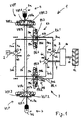
図1は、自動車(不図示)のデュアルモータ油圧式ハイブリット伝動装置1を示す。車両は、例えば、ホイールローダなどのオフハイウェイ車両であってよい。伝動装置1は、内燃エンジン2と油圧回路3とを備える。油圧回路3は、エンジン2と駆動係合される静油圧ポンプ4と、第1の静油圧モータ5と、第2の静油圧モータ6とを有する。静油圧モータ5、6は、第1のポンプ弁PAを通じて、第2のポンプ弁PBを通じて、及び流体ライン20a、20b、30a、30b、40a、40bを通じて、ポンプ4と流体連通する。
FIG. 1 shows a dual motor hydraulic hybrid transmission 1 of an automobile (not shown). The vehicle may be an off-highway vehicle such as a wheel loader, for example. The transmission 1 includes an
ポンプ弁PA、PBの制御位置又はスプール位置が、例えば、電磁力を通じて、又は油圧力を通じて、制御されることができる。後述の例では、ポンプ弁PA、PBは、複数の対応するパイロット弁(不図示)を通じて、制御されることができる。ポンプ弁PA、PB(又は、適用可能であれば、複数の対応するパイロット弁)は、電子制御ユニット(不図示)を通じて、複数の有線又は無線電磁信号を介して、制御されることができる。 The control position or spool position of the pump valves PA, PB can be controlled, for example, through electromagnetic force or through hydraulic pressure. In the example described later, the pump valves PA and PB can be controlled through a plurality of corresponding pilot valves (not shown). Pump valves PA, PB (or a plurality of corresponding pilot valves, if applicable) can be controlled via a plurality of wired or wireless electromagnetic signals through an electronic control unit (not shown).
換言すれば、流体ライン20a、20b、30a、30b、40a、40bは、このようにして、ポンプ4とモータ5、6とを連通し、弁PA、PBは、弁PA、PBを対応する制御位置又は制御構成に切り替えることによって、ポンプ4がモータ5、6のうちの少なくとも1つと選択的に流体的に連通され得るよう構成される。具体的には、弁PA、PBの1つの制御構成では、ポンプ4は、モータ5、6の両方と流体的に連通される。弁PA、PBの別の制御構成では、ポンプ4は、第1のモータ5と流体的に連通され、第2のモータ6から流体的に切り離される。弁PA、PBの別の制御構成では、ポンプ4は、第2のモータ6と流体的に連通され、第1のモータ5から流体的に切り離される。これについては、さらに以下においてより詳細に説明される。
In other words, the
第1のモータ5の伝動シャフト8及び第2のモータ6の伝動シャフト9が、サミングギアボックス10を通じて、伝動装置1の出力シャフト11と選択的に駆動係合される。出力シャフト11は、車両出力部12と駆動係合される、又は選択的に駆動係合される。車両出力部12は、例えば、駆動軸、車両の車軸、最終駆動、及び1つ又は複数の車輪のうちの少なくとも1つを含み得る。ギアボックス10は、出力シャフト11においてモータ5、6により提供されるトルクを選択的に合計するよう構成される。つまり、ギアボックス10は、モータ5、6両方の出力シャフト8、9を出力シャフト11と選択的に同時に連結させ得る。ギアボックス10は、出力シャフト11をモータ5、6の両方から選択的に同時に離すようさらに構成される。ギアボックス10は、所与の時間において、モータ5、6のうちの1つのみを出力シャフト11と選択的に駆動係合させるようさらに構成される。つまり、ギアボックス10は、第2のモータ6を出力シャフトから離しながら、第1のモータ5を出力シャフト11と選択的に駆動係合させるよう構成される。ギアボックス10は、第1のモータ5を出力シャフト11から離しながら、第2のモータ6を出力シャフト11と選択的に駆動係合させるよう構成される。
The transmission shaft 8 of the first motor 5 and the transmission shaft 9 of the
伝動装置1は、高圧蓄圧器7aと低圧蓄圧器7bとを有する油圧蓄圧器組立体7をさらに備える。蓄圧器7a、7bは、圧縮ガス蓄圧器として構成される。蓄圧器7a、7bは、窒素などの不活性ガスを充填した密封のブラダを含む中空容器として構成される。蓄圧器7a、7bは、蓄圧器容器に油などの油圧流体を充填し、又は部分的に充填することによって加圧されてよく、それにより、ブラダに含まれるガスを圧縮する。蓄圧器7a、7bは、ブラダに含まれるガスを散逸させることによって減圧されてよく、これにより、蓄圧器容器に含まれる油圧流体が容器の外へ移動され、それにより、流体流を生成する。
The transmission 1 further includes a hydraulic
蓄圧器組立体7は、高圧蓄圧器弁VHPを通じて、低圧蓄圧器弁VLPを通じて、流体ライン50、60を通じて、油圧回路3と流体連通する。高圧蓄圧器7aは、高圧蓄圧器弁VHPを通じて、流体ライン50、60を通じて、油圧回路3と流体連通し、低圧蓄圧器7bは、低圧蓄圧器弁VLPを通じて、流体ライン50、60を通じて、油圧回路3と流体連通する。
The
蓄圧器弁VHP、VLPの制御位置又はスプール位置は、例えば、電磁力を通じて、又は、油圧力を通じて、制御されることができる。後述の例では、蓄圧器弁VHP、VLPは、複数の対応するパイロット弁(不図示)を通じて、制御されることができる。ポンプ弁PA、PBのように、蓄圧器弁VHP、VLP(又は、適用可能であれば、複数の対応するパイロット弁)は、上述の電子制御ユニット(不図示)を通じて、複数の有線又は無線電磁信号を介して、制御されることができる。 The control position or spool position of the accumulator valves VHP, VLP can be controlled, for example, through electromagnetic force or through hydraulic pressure. In the example described below, the accumulator valves VHP, VLP can be controlled through a plurality of corresponding pilot valves (not shown). Like the pump valves PA, PB, the accumulator valves VHP, VLP (or a plurality of corresponding pilot valves, if applicable) are connected to a plurality of wired or wireless electromagnetics through the electronic control unit (not shown). It can be controlled via a signal.
以下では、ポンプ弁PA、PBの設計と、ポンプ弁PA、PBにより、及び、油圧回路3の流体ライン20a、20b、30a、30b、40a、40bにより提供される、ポンプ4とモータ5、6との間の連通とが詳細に説明される。
In the following, the design of the pump valves PA, PB and the
ポンプ4は、第1の流体ポート4aと第2の流体ポート4bとを有する。第1のモータ5は、第1の流体ポート5aと第2の流体ポート5bとを有する。第2のモータ6は、第1の流体ポート6aと第2の流体ポート6bとを有する。
The
第1のポンプ弁PAは、4つの流体ポートPAa、PAb、PAc、PAdと3つの制御位置PA.1、PA.2、PA.3とを含む4/3ウェイの方向弁である。 The first pump valve PA has four fluid ports PAa, PAb, PAc, PAd and three control positions PA. 1, PA. 2, PA. 4 / 3-way directional valve.
ポンプ弁PAが第1の制御位置PA.1(図1の弁PAの中心位置)に切り替えられた、又はセットされたとき、ポンプ弁PAの全ての流体ポートPAa−dは相互に流体的に連通され、これにより、油圧流体が全ての流体ポートPAa−dの間を流れ得る。 The pump valve PA is in the first control position PA. When switched to 1 (the central position of the valve PA in FIG. 1) or set, all fluid ports PAa-d of the pump valve PA are in fluid communication with each other so that the hydraulic fluid is It can flow between fluid ports PAa-d.
ポンプ弁PAが第2の制御位置PA.2(図1の弁PAの最底部位置)に切り替えられた、又はセットされたとき、第1の流体ポートPAaは、第4の流体ポートPAdと流体的に連通され、これにより、油圧流体が第1の流体ポートPAaと第4の流体ポートPAdとの間を流れてよく、第2の流体ポートPAbは第3の流体ポートPAcと流体的に連通され、これにより、油圧流体が第2の流体ポートPAbと第3の流体ポートPAcとの間を流れてよい。さらに、ポンプ弁PAが第2の制御位置PA.2にあるとき、第1の流体ポートPAa及び第4の流体ポートPAdは両方、第2の流体ポートPAbと第3の流体ポートPAcとの両方から流体的に切り離され、これにより、油圧流体が一方、流体ポートPAaとPAdとの間を流れない場合があり、他方、流体ポートPAbとPAcの間を流れない場合がある。 The pump valve PA is in the second control position PA. When switched or set to 2 (bottom position of valve PA in FIG. 1), the first fluid port PAa is in fluid communication with the fourth fluid port PAd, thereby allowing hydraulic fluid to flow. The first fluid port PAa and the fourth fluid port PAd may flow, and the second fluid port PAb is in fluid communication with the third fluid port PAc so that the hydraulic fluid is in the second fluid port. It may flow between the fluid port PAb and the third fluid port PAc. Furthermore, the pump valve PA is in the second control position PA. 2, both the first fluid port PAa and the fourth fluid port PAd are fluidly disconnected from both the second fluid port PAb and the third fluid port PAc, so that the hydraulic fluid is On the other hand, the fluid ports PAa and PAd may not flow, while the fluid ports PAb and PAc may not flow.
ポンプ弁PAが第3の制御位置PA.3(図1の弁PAの最上部位置)に切り替えられた、又はセットされたとき、第1の流体ポートPAaは、第2の流体ポートPAbと流体的に連通され、これにより、油圧流体が第1の流体ポートPAaと第2の流体ポートPAbとの間を流れてよく、第3の流体ポートPAcは、第4の流体ポートPAdと流体的に連通され、これにより、油圧流体が第3の流体ポートPAcと第4の流体ポートPAdとの間を流れてよい。さらに、ポンプ弁PAが第3の制御位置PA.3にあるとき、第1の流体ポートPAa及び第2の流体ポートPAbは両方、第3の流体ポートPAc及び第4の流体ポートPAdの両方から流体的に切り離され、これにより、油圧流体が一方、流体ポートPAaとPAbとの間を流れない場合があり、他方、流体ポートPAc、PAdとの間を流れない場合がある。 The pump valve PA is in the third control position PA. When switched or set to 3 (the top position of the valve PA in FIG. 1), the first fluid port PAa is in fluid communication with the second fluid port PAb, thereby allowing hydraulic fluid to flow. The third fluid port PAc may flow between the first fluid port PAa and the second fluid port PAb, and the third fluid port PAc is in fluid communication with the fourth fluid port PAd so that the hydraulic fluid is in the third fluid port. Between the first fluid port PAc and the fourth fluid port PAd. Furthermore, the pump valve PA is in the third control position PA. 3, both the first fluid port PAa and the second fluid port PAb are fluidly disconnected from both the third fluid port PAc and the fourth fluid port PAd, so that the hydraulic fluid is , The fluid ports PAa and PAb may not flow, while the fluid ports PAc and PAd may not flow.
第2のポンプ弁PBは、第1のポンプ弁PAと同一である。つまり、第2のポンプ弁も、4つの流体ポートPBa、PBb、PBc、PBdと、3つの制御位置PB.1、PB.2、PB.3とを有する4/3ウェイの方向弁である。第2のポンプ弁PBの3つの制御位置PB.1、PB.2、PB.3における、第2のポンプ弁PBの流体ポートPBaとPBbとPBcとPBdとの間の流体連通/切り離しは、第1のポンプ弁PAに関して説明されたものに類似する。これは、図1の弁PA及びPBの図示から当業者にとっては直ちに明らかである。 The second pump valve PB is the same as the first pump valve PA. That is, the second pump valve also has four fluid ports PBa, PBb, PBc, PBd and three control positions PB. 1, PB. 2, PB. 4/3 way directional valve. Three control positions PB. 1, PB. 2, PB. The fluid communication / disconnection between the fluid ports PBa, PBb, PBc, and PBd of the second pump valve PB at 3 is similar to that described for the first pump valve PA. This will be readily apparent to those skilled in the art from the illustration of valves PA and PB in FIG.
流体ライン20aは、ポンプ4の第1の流体ポート4aを第1のポンプ弁PAの第3の流体ポートPAcと流体的に連通させる。流体ライン20bは、ポンプ4の第2の流体ポート4bを第2のポンプ弁PBの第1の流体ポートPBaと流体的に連通させる。流体ライン30aは、第1のポンプ弁PAの第2の流体ポートPAbを第1のモータ5の第1の流体ポート5aと流体的に連通させる。流体ライン30bは、第2のポンプ弁PBの第4の流体ポートPBdを第1のモータ5の第2の流体ポート5bと流体的に連通させる。流体ライン40aは、第1のポンプ弁PAの第4の流体ポートPAdを第2のモータ6の第1の流体ポート6aと流体的に連通させる。流体ライン40bは、第2のポンプ弁PBの第2の流体ポートPBbを第2のモータ6の第2の流体ポート6bと流体的に連通させる。
The fluid line 20a fluidly communicates the first fluid port 4a of the
上述の制御ユニットは、ポンプ弁PA、PBを制御するよう構成され、これにより、所与の時間において、両方の弁は、それらの第1の制御位置PA.1及びPB.1に、それらの第2の制御位置PA.2及びPB.2に、又は、それらの第3の制御位置PA.3及びPB.3にある。換言すれば、所与の時間において、ポンプ弁PA、PBは、以下においてP.1、P.2及びP.3と称される3つの可能な制御構成のうちの1つにあることができる。第1の制御構成P.1において、第1のポンプ弁PAは、第1の制御位置PA.1にあり、第2のポンプ弁PBは、第1の制御位置PB.1にある。第2の制御構成P.2においては、第1のポンプ弁PAは、第2の制御位置PA.2にあり、第2のポンプ弁PBは、第2の制御位置PB.2にある。第3の制御構成P.3において、第1のポンプ弁PAは、第3の制御位置PA.3にあり、第2のポンプ弁PBは第3の制御位置PB.3にある。 The control unit described above is configured to control the pump valves PA, PB, so that at a given time both valves are in their first control position PA. 1 and PB. 1 to their second control position PA. 2 and PB. 2 or their third control position PA. 3 and PB. 3. In other words, at a given time, the pump valves PA, PB are 1, P.I. 2 and P.I. Can be in one of three possible control configurations, referred to as 3. First control configuration P.I. 1, the first pump valve PA is in the first control position PA. 1 and the second pump valve PB is in the first control position PB. 1 Second control configuration P.I. 2, the first pump valve PA is in the second control position PA. 2 and the second pump valve PB is in the second control position PB. 2. Third control configuration P.I. 3, the first pump valve PA is in the third control position PA. 3 and the second pump valve PB is in the third control position PB. 3.
ポンプ弁PA、PBの設計、及び、ポンプ弁PA、PBと流体ライン20a−b、30a−b、40a−bとを通じたポンプ4とモータ5、6との間の連通に関する上記の説明から、以下の内容が直ちに明らかである。
From the above description of the design of the pump valves PA, PB and the communication between the
ポンプ弁PA、PBが第1の制御構成P.1にあるとき、ポンプ4は、流体ライン20a−b、30a−b、40a−bを含む閉回路において、モータ5、6の両方と流体的に連通される。具体的には、第1の制御構成P.1において、ポンプ4の第1の流体ポート4aは、第1のモータ5の第1の流体ポート5aと、第2のモータ6の第1の流体ポート6aと流体的に連通され、ポンプ4の第2の流体ポート4bは、第1のモータ5の第2の流体ポート5bと、第2のモータ6の第2の流体ポート6bと流体的に連通される。
The pump valves PA and PB have the first control configuration P.P. When at 1, pump 4 is in fluid communication with both
ポンプ弁PA、PBが第2の制御構成P.2にあるとき、ポンプ4は、流体ライン20a−b、30a−bを含む閉回路において、第1のモータ5と流体的に連通され、第2のモータ6から流体的に切り離される。具体的には、第2の制御構成P.2において、ポンプ4の第1の流体ポート4aは、第1のモータ5の第1の流体ポート5aと流体的に連通され、ポンプ4の第2の流体ポート4bは、第1のモータ5の第2の流体ポート5bと流体的に連通される。
The pump valves PA and PB have the second control configuration P.P. When at 2, the
ポンプ弁PA、PBが第3の制御構成P.3にあるとき、ポンプ4は、流体ライン20a−b、40a−bを含む閉回路において、第2のモータ6と流体的に連通され、第1のモータ5から流体的に切り離される。具体的には、第3の制御構成P.2において、ポンプ4の第1の流体ポート4aは、第2のモータ6の第1の流体ポート6aと流体的に連通され、ポンプ4の第2の流体ポート4bは、第2のモータ6の第2の流体ポート6bと流体的に連通される。
The pump valves PA and PB have the third control configuration P.P. 3, the
以下では、蓄圧器弁VHP、VLPの設計、及び、蓄圧器弁VHP、VLP、流体ライン50、60、ポンプ弁PA、PB、及び油圧回路3の流体ライン30a−b、40a−bにより提供される、蓄圧器組立体7とモータ5、6との間の連通が、詳細に説明される。
In the following, the design of the accumulator valves VHP, VLP and the accumulator valves VHP, VLP, the
高圧蓄圧器弁VHPは、3つの流体ポートVHPa、VHPb、VHPcと、3つの制御位置VHP.1、VHP.2、VHP.3とを有する3/3ウェイの方向弁である。 The high pressure accumulator valve VHP has three fluid ports VHPa, VHPb, VHPc and three control positions VHP. 1, VHP. 2, VHP. 3/3 way directional valve.
高圧蓄圧器弁VHPが第1の制御位置VHP.1(図1の弁VHPの中心位置)に切り替えられた、又はセットされたとき、全ての流体ポートVHPa―cは、互いから流体的に切り離され、これにより、油圧流体がポートVHPa―cの間を流れない場合がある。 The high pressure accumulator valve VHP is in the first control position VHP. When switched or set to 1 (the central position of the valve VHP in FIG. 1), all fluid ports VHPa-c are fluidly disconnected from each other, so that hydraulic fluid is connected to port VHPa-c. There may be no flow between them.
高圧蓄圧器弁VHPが第2の制御位置VHP.2(図1の弁VHPの最左の位置)に切り替えられた、又はセットされたとき、第1の流体ポートVHPaは、第2の流体ポートVHPbと流体的に連通され、これにより、油圧流体が第1の流体ポートVHPaと第2の流体ポートVHPbとの間を流れ得る。さらに、高圧蓄圧器弁が第2の制御位置VHP.2にあるとき、第1の流体ポートVHPa及び第2の流体ポートVHPbの両方は第3の流体ポートVHPcから流体的に切り離され、これにより、油圧流体が一方、流体ポートVHPaとVHPbとの間を流れない場合があり、他方、流体ポートVHPcを流れない場合がある。 The high pressure accumulator valve VHP is in the second control position VHP. When switched or set to 2 (the leftmost position of valve VHP in FIG. 1), the first fluid port VHPa is in fluid communication with the second fluid port VHPb, thereby providing hydraulic fluid Can flow between the first fluid port VHPa and the second fluid port VHPb. Further, the high pressure accumulator valve is in the second control position VHP. 2, both the first fluid port VHPa and the second fluid port VHPb are fluidly disconnected from the third fluid port VHPc, so that hydraulic fluid is on the other hand between the fluid ports VHPa and VHPb. May not flow through the fluid port VHPc.
高圧蓄圧器弁VHPが第3の制御位置VHP.3(図1の弁VHPの最右の位置)に切り替えられた、又はセットされたとき、第1の流体ポートVHPaは、第3の流体ポートVHPcと流体的に連通され、これにより、油圧流体が第1の流体ポートVHPaと第3の流体ポートVHPcとの間を流れ得る。さらに、高圧蓄圧器弁が第3の制御位置VHP.3にあるとき、第1の流体ポートVHPa及び第3の流体ポートVHPcの両方は、第2の流体ポートVHPbから流体的に切り離され、これにより、油圧流体が一方、流体ポートVHPaとVHPcとの間を流れない場合があり、他方、流体ポートVHPbを流れない場合がある。 The high pressure accumulator valve VHP is in the third control position VHP. When switched or set to 3 (the rightmost position of the valve VHP in FIG. 1), the first fluid port VHPa is in fluid communication with the third fluid port VHPc, thereby providing hydraulic fluid Can flow between the first fluid port VHPa and the third fluid port VHPc. Further, the high pressure accumulator valve is in the third control position VHP. 3, both the first fluid port VHPa and the third fluid port VHPc are fluidly disconnected from the second fluid port VHPb, so that hydraulic fluid is one of the fluid ports VHPa and VHPc. In some cases, the fluid port VHPb may not flow.
低圧蓄圧器弁VLPは、高圧蓄圧器弁VHPと同一である。つまり、低圧蓄圧器弁VLPも、3つの流体ポートVLPa、VLPb、VLPcと、3つの制御位置VLP.1、VLP.2、VLP.3とを有する3/3ウェイの方向弁である。低圧蓄圧器弁VLPの3つの制御位置VLP.1、VLP.2、VLP.3における、低圧蓄圧器弁VLPの流体ポートVLPaとVLPbとVLPcとの間の流体連通/切り離しは、高圧蓄圧器弁VHPに関して説明されたものに類似する(VLP.2が図1の弁VLPの最右の位置に対応し、VLP.3が最左の位置に対応することを除く)。これは、図1の弁VHP及びVLPの図示から当業者にとっては直ちに明らかである。 The low pressure accumulator valve VLP is the same as the high pressure accumulator valve VHP. That is, the low pressure accumulator valve VLP also includes three fluid ports VLPa, VLPb, and VLPc and three control positions VLP. 1, VLP. 2, VLP. 3/3 way directional valve. Three control positions VLP. 1, VLP. 2, VLP. The fluid communication / disconnection between the fluid ports VLPa, VLPb, and VLPc of the low pressure accumulator valve VLP at 3 is similar to that described for the high pressure accumulator valve VHP (VLP.2 is the valve VLP of FIG. Corresponding to the rightmost position, except that VLP.3 corresponds to the leftmost position). This will be readily apparent to those skilled in the art from the illustration of valves VHP and VLP in FIG.
高圧蓄圧器弁VHPの第1の流体ポートVHPaは(永久に)、高圧蓄圧器7aと流体的に連通される。同様に、低圧蓄圧器弁VLPの第1の流体ポートVLPaは(永久に)、低圧蓄圧器7bと流体的に連通される。流体ライン50は、高圧蓄圧器弁VHPの第2の流体ポートVHPb及び低圧蓄圧器弁VLPの第3の流体ポートVLPcを、第1のポンプ弁PAの第1の流体ポートPAaと流体的に連通させる。流体ライン60は、高圧蓄圧器弁VHPの第3の流体ポートVHPc及び低圧蓄圧器弁VLPの第2の流体ポートVLPbを、第2のポンプ弁PBの第3の流体ポートPBcと流体的に連通させる。
The first fluid port VHPa of the high pressure accumulator valve VHP is (permanently) in fluid communication with the high pressure accumulator 7a. Similarly, the first fluid port VLPa of the low pressure accumulator valve VLP is (permanently) in fluid communication with the low pressure accumulator 7b. The
上述の制御ユニットは、蓄圧器弁VHP、VLPを制御するよう構成され、これにより、所与の時間において、両方の弁は、それらの第1の制御位置VHP.1及びVLP.1に、それらの第2の制御位置VHP.2及びVLP.2に、又は、それらの第3の制御位置VHP.3及びVLP.3にある。換言すれば、所与の時間において、蓄圧器弁VHP、VLPは、以下においてV.1、V.2及びV.3と称される3つの可能な制御構成のうちの1つにあることができる。第1の制御構成V.1において、高圧蓄圧器弁VHPは、第1の制御位置VHP.1にあり、低圧蓄圧器弁VLPは、第1の制御位置VLP.1にある。第2の制御構成V.2において、高圧蓄圧器弁VHPは、第2の制御位置VHP.2にあり、低圧蓄圧器弁VLPは、第2の制御位置VLP.2にある。第3の制御構成V.3において、高圧蓄圧器弁VHPは、第3の制御位置VHP.3にあり、低圧蓄圧器弁VLPは、第3の制御位置VLP.3にある。 The control unit described above is configured to control the accumulator valves VHP, VLP, so that at a given time both valves are in their first control position VHP. 1 and VLP. 1 to their second control position VHP. 2 and VLP. 2 or their third control position VHP. 3 and VLP. 3. In other words, at a given time, the accumulator valves VHP, VLP are V.V. 1, V. 2 and V.I. Can be in one of three possible control configurations, referred to as 3. First control configuration V. 1, the high pressure accumulator valve VHP is in the first control position VHP. 1 and the low pressure accumulator valve VLP is in the first control position VLP. 1 Second control configuration V. 2, the high pressure accumulator valve VHP is in the second control position VHP. 2 and the low pressure accumulator valve VLP is in the second control position VLP. 2. Third control configuration V. 3, the high pressure accumulator valve VHP is in the third control position VHP. 3 and the low pressure accumulator valve VLP is in the third control position VLP. 3.
制御ユニットは、ポンプ弁構成P.1、P.2、P.3と蓄圧器弁構成V.1、V.2、V.3とを独立に制御するようさらに構成される。つまり、ポンプ弁構成P.1、P.2、P.3のうちのそれぞれは、蓄圧器弁構成V.1、V.2、V.3のうちのそれぞれと組み合わされることができる。結果的に、以下においてT.1、T.2、T.3、T.4、T.5、T.6、T.7、T.8、T.9と称される、伝動装置1の合計3×3=9の弁構成がある。これらの構成は、以下の一覧に従って定義される。T.1:P.1+V.1; T.2:P.1+V.2; T.3:P.1+V.3; T.4:P.2+V.1; T.5:P.2+V.2; T.6:P.2+V.3; T.7:P.3+V.1; T.8:P.3+V.2; T.9:P.3+V.3. The control unit has a pump valve configuration P.I. 1, P.I. 2, P.I. 3 and pressure accumulator valve configuration 1, V. 2, V. 3 is further configured to be controlled independently. That is, the pump valve configuration P.I. 1, P.I. 2, P.I. Each of the three pressure accumulator valve configurations V.3. 1, V. 2, V. Can be combined with each of the three. As a result, T. 1, T. 2, T. 3, T.A. 4, T.A. 5, T.A. 6, T. 7, T.A. 8, T.A. There are a total of 3 × 3 = 9 valve configurations of the transmission 1, referred to as 9. These configurations are defined according to the following list. T.A. 1: P.I. 1 + V. 1; 2: P.I. 1 + V. 2; 3: P.I. 1 + V. 3; 4: P.I. 2 + V. 1; 5: P. 2 + V. 2; 6: P. 2 + V. 3; 7: P. 3 + V. 1; 8: P. 3 + V. 2; 9: P. 3 + V. 3.
以下では、異なる弁構成T.1からT.9に関連付けられる、伝動装置1の複数の動作モードが説明される。ポンプ弁PA、PBを通じたポンプ4とモータ5、6との間の流体連通は、詳細に上述されている。ポンプ4とモータ5、6との間の連通が蓄圧器弁VHP,VLPの構成V.1、V.2、V.3からの影響を受けないので、構成T.1−T.9の以下の説明において、一方、蓄圧器7a、7bの間のみの連通、他方、ポンプ4と第1のモータ5と第2のモータ6との間の連通のみがいくぶん詳細に説明される。
In the following, different valve configurations T.P. 1 to T.W. 9, a plurality of operation modes of the transmission 1 are described. The fluid communication between the
弁構成T.1(=P.1+V.1)に関連付けられる動作モードにおいて、蓄圧器組立体7は、油圧回路3から流体的に切り離され、ポンプ4は、第1のモータ5及び第2のモータ6と流体的に連通される(図1を参照)。このモードは、デュアルモータ静油圧伝動装置の標準静油圧モードに対応する。モータ5、6は両方、ポンプ4により駆動される。
Valve configuration 1 (= P.1 + V.1), the
弁構成T.2(=P.1+V.2)に関連付けられる動作モードは、図2に示される。ここ及び以下では、繰り返される複数の特徴が同じ参照符号により示される。再び、ポンプ4は、モータ5、6の両方と流体的に連通される。加えて、蓄圧器組立体7は、モータ5、6の両方と流体的に連通される。具体的には、高圧蓄圧器7aは、第1のモータ5の第1の流体ポート5aと、第2のモータ6の第1の流体ポート6aと流体的に連通され、低圧蓄圧器7bは、第1のモータ5の第2の流体ポート5bと、第2のモータ6の第2の流体ポート6bと流体的に連通される。このモードは、デュアルモータ直列ハイブリットモードに対応する。このモードにおいて、高圧で高圧蓄圧器7aに格納される油圧流体が、モータ5、6の両方を通じて、高圧蓄圧器7aから低圧蓄圧器7bへ移動されてよく、それにより、例えば、車両の前方運動(前方加速度)の間に追加のトルクをモータ5、6に加える。また、このモードにおいて、蓄圧器7a、7bは、車両の後方運動(後方減速度)の間に車両を減速させるのに用いられ得る。
Valve configuration The operation mode associated with 2 (= P.1 + V.2) is shown in FIG. Here and below, repeated features are denoted by the same reference numerals. Again, the
弁構成T.3(=P.1+V.3、不図示)に関連付けられる動作モードにおいて、ポンプ4は再び、モータ5、6の両方と流体的に連通される。再び、蓄圧器組立体7は、モータ5、6の両方と流体的に連通される。構成T.2とは対照的に、構成T.3において、高圧蓄圧器7aは、第1のモータ5の第2の流体ポート5bと、第2のモータ6の第2の流体ポート6bと流体的に連通され、低圧蓄圧器7bは、第1のモータ5の第1の流体ポート5aと、第2のモータ6の第1の流体ポート6aと流体的に連通される。再び、このモードは、デュアルモータ直列ハイブリットモードに対応する。このモードにおいて、蓄圧器組立体7は、車両の前方運動(前方減速度)の間に車両を減速させる、又は、車両の後方運動(後方加速度)の間に車両を加速させるのに用いられ得る。
Valve configuration 3 (= P.1 + V.3, not shown), the
弁構成T.4(=P.2+V.1、不図示)に関連付けられる動作モードにおいて、蓄圧器組立体7は再び、油圧回路3から流体的に切り離される。ポンプ4は第1のモータ5と流体的に連通され、第2のモータ6から流体的に切り離される。このモードは、第1のモータ5のみを用いるシングルモータ静油圧伝動装置の標準静油圧モードに対応する。
Valve configuration 4 (= P.2 + V.1, not shown), the
弁構成T.5(=P.2+V.2、不図示)に関連付けられる動作モードにおいて、ポンプ4は、第1のモータ5と流体的に連通され、第2のモータ6から流体的に切り離される。同時に、蓄圧器組立体7は、第2のモータ6と流体的に連通され、第1のモータ5から流体的に切り離される。具体的には、高圧蓄圧器7aは、第2のモータ6の第1の流体ポート6aと流体的に連通され、低圧蓄圧器7bは、第2のモータ6の第2の流体ポート6bと流体的に連通される。
Valve configuration 5 (= P.2 + V.2, not shown), the
このモードにおいて、ポンプ4、第1のモータ5及び流体ライン20a、30a、20b、30bにより形成される(サブ)回路が、蓄圧器7a、7b、第2のモータ6及び流体ライン50、60、40a、40bにより形成される(サブ)回路から流体的に分離される。第1のモータ5は、ポンプ4のみにより電力供給され、第2のモータ6は、蓄圧器組立体7のみにより電力供給される。ポンプ4により提供されるトルク/電力と、蓄圧器組立体7により提供されるトルク/電力とはギアボックス10においてのみ合計される。従って、たとえ油圧回路3における油圧と蓄圧器組立体7における油圧との間に圧力のミスマッチがあったとしても、伝動装置1は、このモードに切り替えられることができる。このモードは、並列モードに対応し、例えば、前方加速度の間に用いられ得る。
In this mode, the (sub) circuit formed by the
弁構成T.6(=P.2+V.3、不図示)に関連付けられる動作モードは、蓄圧器7a、7bの第2のモータ6との流体連通が置き換えられることを除き、上で説明されている、弁構成T.5に関連付けられるモードと同一である。具体的には、高圧蓄圧器7aはここでは、第2のモータ6の第2の流体ポート6bと流体的に連通され、低圧蓄圧器7bはここでは、第2のモータ6の第1の流体ポート6aと流体的に連通される。上で説明されている構成T.5に関連付けられるモードのように、このモードは、並列モードに対応し、例えば、後方加速度の間に用いられ得る。
Valve configuration 6 (= P.2 + V.3, not shown) is the valve configuration described above, except that the fluid communication of the accumulators 7a, 7b with the
弁構成T.7(不図示)に関連付けられる動作モードにおいて、蓄圧器組立体7は、油圧回路3から流体的に切り離される。ポンプ4は、第2のモータ6と流体的に連通され、第1のモータ5から流体的に切り離される。このモードは、第2のモータ6のみを用いるシングルモータ静油圧伝動装置の標準静油圧モードに対応する。
Valve configuration In the mode of operation associated with 7 (not shown), the
弁構成T.8(=P.3+V.2)に関連付けられる動作モードは図3に示される。このモードは、上で説明されている構成T.5に関連付けられるモードと同様である。しかしながら、T.5に関して、第1のモータ5及び第2のモータ6の機械的な手順が置き換えられる。ポンプ4はここでは、第2のモータ6と流体的に連通され、第1のモータ5から流体的に切り離される。同時に、蓄圧器組立体7は、第1のモータ5と流体的に連通され、第2のモータ6から流体的に切り離される。具体的には、高圧蓄圧器7aは、第1のモータ5の第1の流体ポート5aと流体的に連通され、低圧蓄圧器7bは、第1のモータ5の第2の流体ポート5bと流体的に連通される。
Valve configuration The operation mode associated with 8 (= P.3 + V.2) is shown in FIG. This mode is the configuration T.P. This is the same as the mode associated with 5. However, T.W. 5, the mechanical procedure of the first motor 5 and the
再び、このモードにおいて、ポンプ4、第2のモータ6及び流体ライン20a、40a、20b、40bにより形成される(サブ)回路が、蓄圧器7a、7b、第1のモータ5及び流体ライン50、60、30a、30bにより形成される(サブ)回路から流体的に分離される。第1のモータ5は、蓄圧器組立体7のみにより電力供給され、第2のモータ6は、ポンプ4のみにより電力供給される。ポンプ4により提供されるトルク/電力と蓄圧器組立体7により提供されるトルク/電力とがギアボックス10においてのみ合計される。従って、たとえ油圧回路3における油圧と蓄圧器組立体7における油圧との間に圧力のミスマッチがあったとしても、伝動装置1は、このモードに切り替えられることができる。このモードは、並列モードに対応し、例えば、前方加速度の間に用いられ得る。
Again, in this mode, the (sub) circuit formed by the
弁構成T.9(=P.3+V.3)に関連付けられる動作モードは、図4に示される。これは、蓄圧器7a、7bの第1のモータ5との流体連通が置き換えられることを除き、上で説明されている、弁構成T.8に関連付けられるモードと同一である。具体的には、高圧蓄圧器7aはここでは、第1のモータ5の第2の流体ポート5bと流体的に連通され、低圧蓄圧器7bはここでは、第1のモータ5の第1の流体ポート5aと流体的に連通される。上で説明されている構成T.8に関連付けられるモードのように、このモードは、並列モードに対応し、例えば、後方加速度の間に用いられ得る。 Valve configuration The operation mode associated with 9 (= P.3 + V.3) is shown in FIG. This is the same as that described above, except that the fluid communication of the accumulators 7a, 7b with the first motor 5 is replaced. 8 is the same as the mode associated with 8. Specifically, the high pressure accumulator 7a is here in fluid communication with the second fluid port 5b of the first motor 5, and the low pressure accumulator 7b is here a first fluid of the first motor 5. In fluid communication with port 5a. Configuration T. described above. Like the mode associated with 8, this mode corresponds to the parallel mode and can be used, for example, during backward acceleration.
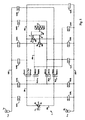
図5は、図1−4の伝動装置1の変形例であるデュアルモータ油圧式ハイブリット伝動装置を示す。上記のように、繰り返される複数の特徴が同じ参照符号により示される。図5の実施形態は、蓄圧器7a、7bが、ポンプ弁PA、PBの制御構成と殆ど独立に、モータ5、6と選択的に流体的に連通されることができるという点において、図1−4の実施形態と異なる。加えて、ポンプ弁PA、PBのそれぞれは、2つの2/2弁により実現される。より具体的には、弁PAは、2つの弁PA.A及びPA.Bにより実現され、弁PBは、2つの弁PB.A及びPB.Bにより実現される。
FIG. 5 shows a dual motor hydraulic hybrid transmission that is a modification of the transmission 1 of FIGS. As described above, repeated features are indicated by the same reference numerals. The embodiment of FIG. 5 differs in that the accumulators 7a, 7b can be selectively fluidly communicated with the
当業者であれば、図5の概略図から容易に理解するように、ポンプ4は、モータ5、6の両方と、又はモータ5、6のうちの1つのみと、選択的に流体的に連通されることができる。
Those skilled in the art will readily appreciate from the schematic diagram of FIG. 5 that the
例えば、ポンプ4は、第1のポンプ弁PA.A及びPA.Bを第1の制御位置PA.A.1及びPA.B.1(図5に示されているように)にそれぞれ切り替えることにより、かつ、同時に、第2のポンプ弁PB.A及びPB.Bを第1の制御位置PB.A.1及びPB.B.1にそれぞれ切り替えることにより、モータ5、6の両方と流体的に連通されることができる。ポンプ4は、ポンプ弁PA.A、PA.B、PB.A及びPB.Bのそれぞれを、それらのそれぞれの制御位置PA.A.1、PA.B.2、PB.A.2及びPB.B.2に切り替えることにより、第1のモータ5と流体的に連通されることができ、同時に、第2のモータ6から流体的に切り離されることができる。ポンプ4は、ポンプ弁PA.A、PA.B、PB.A及びPB.Bのそれぞれを、それらのそれぞれの制御位置PA.A.2、PA.B.1、PB.A.1及びPB.B.2に切り替えることにより、第2のモータ6と流体的に連通されることができ、同時に、第1のモータ5から流体的に切り離されることができる。
For example, the
高圧蓄圧器7aと低圧蓄圧器7bとを含む蓄圧器組立体7は、2/2弁VHP1、VHP2、VHP3、VHP4、VHP5、VHP6、VLP1、VLP2、VLP3、VLP4、VLP5、VLP6を用いて、油圧回路と選択的に流体的に連通されることができる。弁VHP1−6とVLP1−6とのそれぞれは、開位置及び閉位置を有する2/2ウェイ閉止弁である。
A
高圧蓄圧器7aは、6つの高圧蓄圧器弁VHP1、VHP2、VHP3、VHP4、VHP5、VHP6のセットを通じて、流体ライン20a、30a、40a、20b、30b、40bのそれぞれと選択的に流体的に連通されることができる。
The high pressure accumulator 7a is selectively in fluid communication with each of the
弁VHP1は、開位置にあるとき、その流体ライン100を介して、高圧蓄圧器7aを流体ライン20aと選択的に流体的に連通させる。弁VHP1は、閉位置にあるとき、流体ライン20aを高圧蓄圧器7aから分離させる。
When the valve VHP1 is in the open position, the high pressure accumulator 7a is selectively in fluid communication with the fluid line 20a via the
弁VHP2は、開位置にあるとき、その流体ライン100を介して、高圧蓄圧器7aを流体ライン20bと選択的に流体的に連通させる。弁VHP2は、閉位置にあるとき、流体ライン20bを高圧蓄圧器7aから分離させる。
When in the open position, valve VHP2 selectively fluidly communicates high pressure accumulator 7a with fluid line 20b via
弁VHP3は、開位置にあるとき、その流体ライン100を介して、高圧蓄圧器7aを流体ライン30aと選択的に流体的に連通させる。弁VHP3は、閉位置にあるとき、流体ライン30aを高圧蓄圧器7aから分離させる。
When the valve VHP3 is in the open position, the high pressure accumulator 7a is selectively in fluid communication with the
弁VHP4は、開位置にあるとき、その流体ライン100を介して、高圧蓄圧器7aを流体ライン40aと選択的に流体的に連通させる。弁VHP4は、閉位置にあるとき、流体ライン40aを高圧蓄圧器7aから分離させる。
Valve VHP4, when in the open position, selectively fluidly communicates high pressure accumulator 7a with fluid line 40a via its
弁VHP5は、開位置にあるとき、その流体ライン100を介して、高圧蓄圧器7aを流体ライン40bと選択的に流体的に連通させる。弁VHP5は、閉位置にあるとき、流体ライン40bを高圧蓄圧器7aから分離させる。
When the valve VHP5 is in the open position, the high pressure accumulator 7a is selectively in fluid communication with the fluid line 40b via the
弁VHP6は、開位置にあるとき、その流体ライン100を介して、高圧蓄圧器7aを流体ライン30bと選択的に流体的に連通させる。弁VHP6は、閉位置にあるとき、流体ライン30bを高圧蓄圧器7aから分離させる。
When the valve VHP6 is in the open position, the high pressure accumulator 7a is selectively in fluid communication with the
従って、弁VHP1、VHP2、VHP3、VHP4、VHP5、VHP6の組み合わせが、高圧蓄圧器7aを油圧回路3から切り離すこと、高圧蓄圧器7aを第1のモータ5の第1の流体ポート5aと流体的に連通させること、高圧蓄圧器7aを第2のモータ6の第1の流体ポート6aと流体的に連通させること、高圧蓄圧器7aを第1のモータ5の第2の流体ポート5bと流体的に連通させること、高圧蓄圧器7aを第2のモータ6の第2の流体ポート6bと流体的に連通させること、低圧蓄圧器7bを第1のモータ5の第1の流体ポート5aと、第2のモータ6の第1の流体ポート6aと流体的に連通させること、及び、低圧蓄圧器7bを第1のモータ5の第2の流体ポート5bと、第2のモータ6の第2の流体ポート6bと流体的に連通させることのうちの選択的に1つに用いられることができるということが、当業者であれば、容易に理解されるものである。
Therefore, the combination of the valves VHP1, VHP2, VHP3, VHP4, VHP5, VHP6 disconnects the high pressure accumulator 7a from the
さらに、ポンプ弁PA.A、PA.B、PB.A、PB.Bがそれぞれ、それらの第1の制御位置PA.A.1、PA.B.1、PB.A.1、PB.B.1に切り替えられたとき、高圧蓄圧器7aは同時に、弁VHP1を通じて、第1のモータ5及び第2のモータ6のそれぞれの第1の流体ポート5a、6aと流体的に連通され得る。同様に、ポンプ弁PA.A、PA.B、PB.A、PB.Bがそれぞれ、それらの第1の制御位置PA.A.1、PA.B.1、PB.A.1、PB.B.1に切り替えられたとき、高圧蓄圧器7aは同時に、弁VHP2を通じて、第1のモータ5及び第2のモータ6のそれぞれの第2の流体ポート5b、6bと流体的に連通され得る。
Furthermore, the pump valve PA. A, PA. B, PB. A, PB. B are respectively their first control positions PA. A. 1, PA. B. 1, PB. A. 1, PB. B. When switched to 1, the high pressure accumulator 7a can simultaneously be in fluid communication with the respective first fluid ports 5a, 6a of the first motor 5 and the
類似する方式において、低圧蓄圧器7bは、低圧蓄圧器弁VLP1、VLP2、VLP3、VLP4、VLP5、VLP6のセットを通じて、流体ライン20a、20b、30a、30b、40a、40bのそれぞれと選択的に流体的に連通されることができる。
In a similar manner, the low pressure accumulator 7b is selectively fluidic with each of the
弁VLP1は、開位置にあるとき、その流体ライン100を介して、高圧蓄圧器7aを流体ライン20aと選択的に流体的に連通させる。弁VLP1は、閉位置にあるとき、流体ライン20aを高圧蓄圧器7aから分離させる。
When in the open position, the valve VLP1 selectively fluidly communicates the high pressure accumulator 7a with the fluid line 20a via the
弁VLP2は、開位置にあるとき、その流体ライン100を介して、高圧蓄圧器7aを流体ライン20bと選択的に流体的に連通させる。弁VLP2は、閉位置にあるとき、流体ライン20bを高圧蓄圧器7aから分離させる。
When in the open position, the valve VLP2 selectively fluidly communicates the high pressure accumulator 7a with the fluid line 20b via the
弁VLP3は、開位置にあるとき、その流体ライン100を介して、高圧蓄圧器7aを流体ライン30bと選択的に流体的に連通させる。弁VLP3は、閉位置にあるとき、流体ライン30bを高圧蓄圧器7aから分離させる。
When in the open position, the valve VLP3 selectively fluidly communicates the high pressure accumulator 7a with the
弁VLP4は、開位置にあるとき、その流体ライン100を介して、高圧蓄圧器7aを流体ライン40bと選択的に流体的に連通させる。弁VLP4は、閉位置にあるとき、流体ライン40bを高圧蓄圧器7aから分離させる。
When the valve VLP4 is in the open position, the high pressure accumulator 7a is selectively in fluid communication with the fluid line 40b via the
弁VLP5は、開位置にあるとき、その流体ライン100を介して、高圧蓄圧器7aを流体ライン40aと選択的に流体的に連通させる。弁VLP5は、閉位置にあるとき、流体ライン40aを高圧蓄圧器7aから分離させる。
When the valve VLP5 is in the open position, the high pressure accumulator 7a is selectively in fluid communication with the fluid line 40a via the
弁VLP6は、開位置にあるとき、その流体ライン100を介して、高圧蓄圧器7aを流体ライン30aと選択的に流体的に連通させる。弁VLP6は、閉位置にあるとき、流体ライン30aを高圧蓄圧器7aから分離させる。
When the valve VLP6 is in the open position, the high pressure accumulator 7a is selectively in fluid communication with the
従って、弁VLP1、VLP2、VLP3、VLP4、VLP5、VLP6が、低圧蓄圧器7bを油圧回路3から切り離すこと、低圧蓄圧器7bを第1のモータ5の第1の流体ポート5aと流体的に連通させること、低圧蓄圧器7bを第2のモータ6の第1の流体ポート6aと流体的に連通させること、低圧蓄圧器7bを第1のモータ5の第2の流体ポート5bと流体的に連通させること、低圧蓄圧器7bを第2のモータ6の第2の流体ポート6bと流体的に連通させること、低圧蓄圧器7bを第1のモータ5の第1の流体ポート5aと、第2のモータ6の第1の流体ポート6aと流体的に連通させること、及び、低圧蓄圧器7bを第1のモータ5の第2の流体ポート5bと、第2のモータ6の第2の流体ポート6bと流体的に連通させることのうちの選択的に1つに用いられることができるということが、当業者であれば、容易に理解されるものである。
Therefore, the valves VLP1, VLP2, VLP3, VLP4, VLP5, VLP6 disconnect the low pressure accumulator 7b from the
さらに、ポンプ弁PA.A、PA.B、PB.A、PB.Bが、それらの第1の制御位置PA.A.1、PA.B.1、PB.A.1、PB.B.1にそれぞれ切り替えられたとき、低圧蓄圧器7bは同時に、弁VLP1を通じて、第1のモータ5及び第2のモータ6のそれぞれの第1の流体ポート5a、6aと流体的に連通され得る。同様に、ポンプ弁PA.A、PA.B、PB.A、PB.Bが、それらの第1の制御位置PA.A.1、PA.B.1、PB.A.1、PB.B.1にそれぞれ切り替えられたとき、低圧蓄圧器7bは同時に、弁VLP2を通じて、第1のモータ5及び第2のモータ6の第2の流体ポート5b、6bと流体的に連通され得る。
Furthermore, the pump valve PA. A, PA. B, PB. A, PB. B are their first control positions PA. A. 1, PA. B. 1, PB. A. 1, PB. B. When switched to 1, respectively, the low pressure accumulator 7b can simultaneously be in fluid communication with the respective first fluid ports 5a, 6a of the first motor 5 and the
加えて、さらなる安全性及び漏れを低減させるために、2つの追加の2/2弁(例えば、VHP及びVLP)が、蓄圧器7a及び7bをライン100及び200からそれぞれ分離させるのに用いられることができる。
In addition, two additional 2/2 valves (eg, VHP and VLP) are used to isolate accumulators 7a and 7b from
従って、当業者は、図5の伝動装置が図1から図4の伝動装置1と同じ動作モードで動作され得る方法を容易に理解する。 Accordingly, those skilled in the art will readily understand how the transmission of FIG. 5 can be operated in the same mode of operation as the transmission 1 of FIGS.
現在提案されている、シンプルな直列ハイブリッドモードに関する伝動装置の利点は、任意のレベルの蓄圧器圧で機械的伝動装置入力においてトルクを合計する能力にあり、こうして、蓄圧器圧を道路負荷から分離する。加えて、たとえ標準静油圧モードにあったとしても、それは2つのモータのうちの1つを油圧切り離しにすることを可能にし、こうして、損失を低減させる。 The currently proposed transmission advantage for the simple series hybrid mode is the ability to sum torque at the mechanical transmission input at any level of accumulator pressure, thus separating the accumulator pressure from the road load. To do. In addition, even when in the standard hydrostatic mode, it allows one of the two motors to be hydraulically disconnected, thus reducing losses.
複数の特定の実施形態において、複数のモードのうちの一部を除去することによって回路を単純化することが可能な場合がある。特に、図1−4において、複数の基本動作モード及び各モードを得るための油圧制御デバイスの動作を示す。特に、3/3蓄圧器弁(又は異なる実施形態を有するそれらの均等な実現)が、4/3ライン弁が直列と並列モードとの間を切り替えながら、各蓄圧器を、油圧回路3の高圧ラインと、油圧回路3の低圧ラインと連通させる、又は何れも連通させない機能を解決する。直列モードは、両方のモータが同じ圧力源と連通されているとき、中心位置に対応する。一方、並列モードは、ポンプを第1のモータに連通させ、蓄圧器を第2のモータに連通させることによって実現される。この構成において、複数の蓄圧器弁を切り替えることが、第2のモータに対して作用する圧力を変える(ブースティング対再生からの切り替えと同等)。
In certain embodiments, it may be possible to simplify the circuit by removing some of the modes. In particular, FIGS. 1-4 show a plurality of basic operation modes and the operation of the hydraulic control device to obtain each mode. In particular, the 3/3 pressure accumulator valves (or their equivalent realization with different embodiments) allow each pressure accumulator to be connected to the high pressure of the
異なる電気装置も可能である。異なる電気装置は、2つのモータの両方に一緒に電力供給するものと対照的に、1つのモータを駆動させる発電機ともう1つのモータを駆動させる電池とを含む。異なる電気装置は、特定の条件においてパワーエレクトロニクスの損失を低減させることによって全体的な効率から見て何らかの利点を提供する。 Different electrical devices are possible. Different electrical devices include a generator that drives one motor and a battery that drives another motor as opposed to powering both of the two motors together. Different electrical devices offer some advantage in terms of overall efficiency by reducing power electronics losses in certain conditions.
Claims (12)
動力源(2)と、
油圧回路(3)と、
油圧蓄圧器組立体(7)と、
1つ又は複数の制御弁(PA、PB、VHP、VLP)と、
出力シャフト(11)と
を備え、
前記油圧回路(3)は、
前記動力源(2)と駆動係合され、又は選択的に駆動係合される油圧ポンプ(4)と、
前記油圧ポンプ(4)と流体連通される第1の油圧モータ(5)と、
前記油圧ポンプ(4)と流体連通される第2の油圧モータ(6)と
を有し、
前記油圧蓄圧器組立体(7)は、高圧蓄圧器(7a)と、低圧蓄圧器(7b)とを有し、前記油圧蓄圧器組立体(7)は、前記油圧回路(3)と流体連通され、
前記第1の油圧モータ(5)は、前記出力シャフト(11)と駆動係合され、又は選択的に駆動係合され、
前記第2の油圧モータ(6)は、前記出力シャフト(11)と駆動係合され、又は選択的に駆動係合され、
前記複数の制御弁(PA、PB、VHP、VLP)は選択的に、前記油圧ポンプ(4)を前記第2の油圧モータ(6)から流体的に切り離しながら、前記油圧ポンプ(4)を前記第1の油圧モータ(5)と流体的に連通させ、かつ、同時に、
前記油圧蓄圧器組立体(7)を前記第1の油圧モータ(5)から流体的に切り離しながら、前記油圧蓄圧器組立体(7)を前記第2の油圧モータ(6)と流体的に連通させ、
前記複数の制御弁(PA、PB、VHP、VLP)は選択的に、
前記油圧ポンプ(4)を前記第1の油圧モータ(5)から流体的に切り離しながら、前記油圧ポンプ(4)を前記第2の油圧モータ(6)と流体的に連通させ、かつ、同時に、
前記油圧蓄圧器組立体(7)を前記第2の油圧モータ(6)から流体的に切り離しながら、前記油圧蓄圧器組立体(7)を前記第1の油圧モータ(5)と流体的に連通させる、
デュアルモータ油圧式ハイブリット伝動装置(1、1')。 A dual motor hydraulic hybrid transmission (1, 1 '),
Power source (2);
A hydraulic circuit (3);
A hydraulic pressure accumulator assembly (7);
One or more control valves (PA, PB, VHP, VLP);
An output shaft (11) and
The hydraulic circuit (3)
A hydraulic pump (4) drivingly engaged or selectively drivingly engaged with the power source (2);
A first hydraulic motor (5) in fluid communication with the hydraulic pump (4);
A second hydraulic motor (6) in fluid communication with the hydraulic pump (4);
The hydraulic pressure accumulator assembly (7) has a high pressure accumulator (7a) and a low pressure accumulator (7b), and the hydraulic pressure accumulator assembly (7) is in fluid communication with the hydraulic circuit (3). And
The first hydraulic motor (5) is drivingly engaged or selectively drivingly engaged with the output shaft (11);
The second hydraulic motor (6) is drivingly engaged or selectively drivingly engaged with the output shaft (11);
The plurality of control valves (PA, PB, VHP, VLP) selectively disconnect the hydraulic pump (4) from the second hydraulic motor (6) while selectively disconnecting the hydraulic pump (4). In fluid communication with the first hydraulic motor (5) and at the same time,
The hydraulic pressure accumulator assembly (7) is in fluid communication with the second hydraulic motor (6) while the hydraulic pressure accumulator assembly (7) is fluidly disconnected from the first hydraulic motor (5). Let
The plurality of control valves (PA, PB, VHP, VLP) are selectively,
Fluidly disconnecting the hydraulic pump (4) from the first hydraulic motor (5) while fluidly communicating the hydraulic pump (4) with the second hydraulic motor (6);
The hydraulic pressure accumulator assembly (7) is in fluid communication with the first hydraulic motor (5) while the hydraulic pressure accumulator assembly (7) is fluidly disconnected from the second hydraulic motor (6). Let
Dual motor hydraulic hybrid transmission (1, 1 ').
前記油圧ポンプ(4)を前記第1の油圧モータ(5)と前記第2の油圧モータ(6)とに同時に流体的に連通させる、
請求項1に記載のデュアルモータ油圧式ハイブリット伝動装置(1、1')。 The plurality of control valves (PA, PB, VHP, VLP) are further selectively,
The hydraulic pump (4) is in fluid communication with the first hydraulic motor (5) and the second hydraulic motor (6) simultaneously;
The dual motor hydraulic hybrid transmission (1, 1 ') according to claim 1.
前記ポンプ弁(PA、PB)は、前記油圧ポンプ(4)と前記第1の油圧モータ(5)及び前記第2の油圧モータ(6)との間の流体連通を提供し、前記ポンプ弁(PA、PB)は、3つの制御位置又は制御構成を含み、
前記ポンプ弁(PA、PB)が第1の位置又は構成にセットされたとき、前記ポンプ弁(PA、PB)は、前記油圧ポンプ(4)を前記第1の油圧モータ(5)と、前記第2の油圧モータ(6)とに流体的に連通させ、
前記ポンプ弁(PA、PB)が第2の位置又は構成にセットされたとき、前記ポンプ弁(PA、PB)は、前記油圧ポンプ(4)を前記第1の油圧モータ(5)と流体的に連通させ、前記油圧ポンプ(4)を前記第2の油圧モータ(6)から流体的に切り離し、
前記ポンプ弁(PA、PB)が第3の位置又は構成にセットされたとき、前記ポンプ弁(PA、PB)は、前記油圧ポンプ(4)を前記第2の油圧モータ(6)と流体的に連通させ、前記油圧ポンプ(4)を前記第1の油圧モータ(5)から流体的に切り離す、
請求項1または2に記載のデュアルモータ油圧式ハイブリット伝動装置(1、1')。 The plurality of control valves (PA, PB, VHP, VLP) have at least one pump valve (PA, PB),
The pump valves (PA, PB) provide fluid communication between the hydraulic pump (4) and the first hydraulic motor (5) and the second hydraulic motor (6). PA, PB) includes three control positions or control configurations;
When the pump valve (PA, PB) is set to the first position or configuration, the pump valve (PA, PB) is configured to connect the hydraulic pump (4) to the first hydraulic motor (5), Fluidly communicating with the second hydraulic motor (6);
When the pump valve (PA, PB) is set to the second position or configuration, the pump valve (PA, PB) fluidizes the hydraulic pump (4) with the first hydraulic motor (5). And hydraulically disconnecting the hydraulic pump (4) from the second hydraulic motor (6),
When the pump valve (PA, PB) is set to the third position or configuration, the pump valve (PA, PB) fluidizes the hydraulic pump (4) with the second hydraulic motor (6). Fluidly disconnecting the hydraulic pump (4) from the first hydraulic motor (5),
The dual motor hydraulic hybrid transmission (1, 1 ') according to claim 1 or 2.
前記複数の制御弁(PA、PB、VHP、VLP)は、第1のポンプ弁(PA)を有し、前記第1のポンプ弁(PA)は、前記油圧ポンプ(4)の前記第1の流体ポート(4a)と、前記第1の油圧モータ(5)の前記第1の流体ポート(5a)と、前記第2の油圧モータ(6)の前記第1の流体ポート(6a)との間の流体連通を提供し、前記第1のポンプ弁(PA)は、3つの制御位置を有し、
前記第1のポンプ弁(PA)が第1の制御位置にセットされたとき、前記第1のポンプ弁(PA)は、前記油圧ポンプ(4)の前記第1の流体ポート(4a)を、前記第1の油圧モータ(5)の前記第1の流体ポート(5a)と、前記第2の油圧モータ(6)の前記第1の流体ポート(6a)とに流体的に連通させ、
前記第1のポンプ弁(PA)が第2の制御位置にセットされたとき、前記第1のポンプ弁(PA)は、前記油圧ポンプ(4)の前記第1の流体ポート(4a)を前記第1の油圧モータ(5)の前記第1の流体ポート(5a)と流体的に連通させ、前記油圧ポンプ(4)の前記第1の流体ポート(4a)を前記第2の油圧モータ(6)の前記第1の流体ポート(6a)から流体的に切り離し、
前記第1のポンプ弁(PA)が第3の制御位置にセットされたとき、前記第1のポンプ弁(PA)は、前記油圧ポンプ(4)の前記第1の流体ポート(4a)を前記第2の油圧モータ(6)の前記第1の流体ポート(6a)と流体的に連通させ、前記油圧ポンプ(4)の前記第1の流体ポート(4a)を前記第1の油圧モータ(5)の前記第1の流体ポート(5a)から流体的に切り離し、
前記複数の制御弁(PA、PB、VHP、VLP)は、第2のポンプ弁(PB)を有し、前記第2のポンプ弁(PB)は、前記油圧ポンプ(4)の前記第2の流体ポートと、前記第1の油圧モータ(5)の前記第2の流体ポート(5b)と、前記第2の油圧モータ(6)の前記第2の流体ポート(6b)との間の流体連通を提供し、前記第2のポンプ弁(PB)は、3つの制御位置を有し、
前記第2のポンプ弁(PB)が第1の制御位置にセットされたとき、前記第2のポンプ弁(PB)は、前記油圧ポンプ(4)の前記第2の流体ポートを、前記第1の油圧モータ(5)の前記第2の流体ポート(5b)と、前記第2の油圧モータ(6)の前記第2の流体ポート(6b)とに流体的に連通させ、
前記第2のポンプ弁(PB)が第2の制御位置にセットされたとき、前記第2のポンプ弁(PB)は、前記油圧ポンプ(4)の前記第2の流体ポートを前記第1の油圧モータ(5)の前記第2の流体ポート(5b)と流体的に連通させ、前記油圧ポンプ(4)の前記第2の流体ポートを前記第2の油圧モータ(6)の前記第2の流体ポート(6b)から流体的に切り離し、
前記第2のポンプ弁(PB)が第3の制御位置にセットされたとき、前記第2のポンプ弁(PB)は、前記油圧ポンプ(4)の前記第2の流体ポートを前記第2の油圧モータ(6)の前記第2の流体ポート(6b)と流体的に連通させ、前記油圧ポンプ(4)の前記第2の流体ポートを前記第1の油圧モータ(5)の前記第2の流体ポート(5b)から流体的に切り離す、
請求項3に記載のデュアルモータ油圧式ハイブリット伝動装置(1、1')。 The hydraulic pump (4), the first hydraulic motor (5), and the second hydraulic motor (6) each include a first fluid port and a second fluid port,
The plurality of control valves (PA, PB, VHP, VLP) have a first pump valve (PA), and the first pump valve (PA) is the first pump valve of the hydraulic pump (4). Between a fluid port (4a), the first fluid port (5a) of the first hydraulic motor (5), and the first fluid port (6a) of the second hydraulic motor (6) The first pump valve (PA) has three control positions;
When the first pump valve (PA) is set to the first control position, the first pump valve (PA) connects the first fluid port (4a) of the hydraulic pump (4), Fluidly communicating with the first fluid port (5a) of the first hydraulic motor (5) and the first fluid port (6a) of the second hydraulic motor (6);
When the first pump valve (PA) is set to the second control position, the first pump valve (PA) connects the first fluid port (4a) of the hydraulic pump (4) to the first pump valve (PA). The first hydraulic port (4a) of the hydraulic pump (4) is fluidly connected to the first fluid port (5a) of the first hydraulic motor (5), and the second hydraulic motor (6 ) Fluidly decoupled from the first fluid port (6a) of
When the first pump valve (PA) is set to the third control position, the first pump valve (PA) connects the first fluid port (4a) of the hydraulic pump (4) to the The first hydraulic port (4a) of the hydraulic pump (4) is in fluid communication with the first fluid port (6a) of the second hydraulic motor (6), and the first hydraulic motor (5 ) Fluidly decoupled from the first fluid port (5a) of
The plurality of control valves (PA, PB, VHP, VLP) have a second pump valve (PB), and the second pump valve (PB) is the second pump valve of the hydraulic pump (4). Fluid communication between a fluid port, the second fluid port (5b) of the first hydraulic motor (5), and the second fluid port (6b) of the second hydraulic motor (6) The second pump valve (PB) has three control positions;
When the second pump valve (PB) is set to the first control position, the second pump valve (PB) connects the second fluid port of the hydraulic pump (4) to the first fluid port. and said second fluid port of the hydraulic motor (5) of (5b), fluidly communicates to said second of said second fluid ports of the hydraulic motor (6) (6b),
When the second pump valve (PB) is set at the second control position, the second pump valve (PB) connects the second fluid port of the hydraulic pump (4) to the first fluid port. The second fluid port (5b) of the hydraulic motor (5) is in fluid communication with the second fluid port of the hydraulic pump (4) and the second fluid port of the second hydraulic motor (6). Fluidly disconnecting from the fluid port (6b);
When the second pump valve (PB) is set to the third control position, the second pump valve (PB) connects the second fluid port of the hydraulic pump (4) to the second fluid port. The second fluid port (6b) of the hydraulic motor (6) is in fluid communication with the second fluid port of the hydraulic pump (4) and the second fluid port of the first hydraulic motor (5). Fluidly disconnecting from the fluid port (5b),
The dual motor hydraulic hybrid transmission (1, 1 ') according to claim 3.
前記油圧蓄圧器組立体(7)を、前記第1の油圧モータ(5)と前記第2の油圧モータ(6)とに同時に流体的に連通させる、
請求項1から4の何れか一項に記載のデュアルモータ油圧式ハイブリット伝動装置(1、1')。 The plurality of control valves (PA, PB, VHP, VLP) are further selectively,
The hydraulic pressure accumulator assembly (7) is in fluid communication with the first hydraulic motor (5) and the second hydraulic motor (6) simultaneously;
The dual motor hydraulic hybrid transmission (1, 1 ') according to any one of claims 1 to 4.
前記複数の制御弁(PA、PB、VHP、VLP)は、
前記油圧蓄圧器組立体(7)を、前記第1の油圧モータ(5)及び前記第2の油圧モータ(6)のうちの1つと又は両方と流体的に連通させることが、
前記高圧蓄圧器(7a)を前記第1の流体ポートと、又は複数の前記第1の流体ポートとに流体的に連通させ、かつ、同時に、前記低圧蓄圧器(7b)を前記第2の流体ポートと、又は複数の前記第2の流体ポートとに流体的に連通させること、及び、
前記高圧蓄圧器(7a)を前記第2の流体ポートと、又は複数の前記第2の流体ポートとに流体的に連通させ、かつ、同時に、前記低圧蓄圧器(7b)を前記第1の流体ポートと、又は複数の前記第1の流体ポートとに流体的に連通させること
のうちの1つを選択的に含む
よう構成される、
請求項1から5の何れか一項に記載のデュアルモータ油圧式ハイブリット伝動装置(1、1')。 The first hydraulic motor (5) and the second hydraulic motor (6) have a first fluid port (5a, 6a) and a second fluid port (5b, 6b), respectively.
The plurality of control valves (PA, PB, VHP, VLP)
Fluidly communicating the hydraulic accumulator assembly (7) with one or both of the first hydraulic motor (5) and the second hydraulic motor (6);
The high pressure accumulator (7a) is in fluid communication with the first fluid port or the plurality of first fluid ports, and at the same time, the low pressure accumulator (7b) is configured with the second fluid. Fluidly communicating with a port or a plurality of said second fluid ports; and
The high pressure accumulator (7a) is in fluid communication with the second fluid port or the plurality of second fluid ports, and at the same time, the low pressure accumulator (7b) is configured with the first fluid. Configured to selectively include one of fluid communication with a port or a plurality of said first fluid ports;
The dual motor hydraulic hybrid transmission (1, 1 ') according to any one of claims 1 to 5.
前記蓄圧器弁(VHP、VLP)は、前記油圧蓄圧器組立体(7)と前記第1の油圧モータ及び前記第2の油圧モータとの間の流体連通を提供し、前記蓄圧器弁(VHP、VLP)は、少なくとも3つの制御位置又は制御構成を含み、
前記蓄圧器弁(VHP、VLP)は、
前記蓄圧器弁(VHP、VLP)が第1の位置又は構成にセットされたとき、前記油圧蓄圧器組立体(7)は、前記油圧回路(3)から流体的に切り離され、
前記蓄圧器弁(VHP、VLP)が第2の位置又は構成にセットされたとき、前記高圧蓄圧器(7a)は、前記第1の油圧モータ(5)及び前記第2の油圧モータ(6)のうちの少なくとも1つの第1の流体ポートと選択的に流体的に連通され、前記低圧蓄圧器(7b)は、前記高圧蓄圧器(7a)が流体的に連通されている前記第1の油圧モータ又は前記第2の油圧モータ、若しくは前記第1の油圧モータ及び前記第2の油圧モータの対応する第2の流体ポート又は複数の第2の流体ポートと流体的に連通され、
前記蓄圧器弁(VHP、VLP)が第3の位置又は構成にセットされたとき、前記高圧蓄圧器(7a)は、前記第1の油圧モータ(5)及び前記第2の油圧モータ(6)のうちの少なくとも1つの前記第2の流体ポートと選択的に流体的に連通され、前記低圧蓄圧器(7b)は、前記高圧蓄圧器(7a)が流体的に連通されている前記第1の油圧モータ又は前記第2の油圧モータ、若しくは前記第1の油圧モータ及び前記第2の油圧モータの対応する前記第1の流体ポート又は複数の第1の流体ポートと流体的に連通される
よう構成される、
請求項1から6の何れか一項に記載のデュアルモータ油圧式ハイブリット伝動装置(1、1')。 The plurality of control valves (PA, PB, VHP, VLP) have at least one accumulator valve (VHP, VLP),
The accumulator valves (VHP, VLP) provide fluid communication between the hydraulic accumulator assembly (7) and the first hydraulic motor and the second hydraulic motor, and the accumulator valve (VHP). , VLP) includes at least three control positions or control configurations;
The accumulator valves (VHP, VLP)
When the pressure accumulator valve (VHP, VLP) is set to the first position or configuration, the hydraulic pressure accumulator assembly (7) is fluidly disconnected from the hydraulic circuit (3);
When the accumulator valve (VHP, VLP) is set to the second position or configuration, the high-pressure accumulator (7a) includes the first hydraulic motor (5) and the second hydraulic motor (6). And the low pressure accumulator (7b) is in fluid communication with the high pressure accumulator (7a). In fluid communication with a motor or the second hydraulic motor , or a corresponding second fluid port or plurality of second fluid ports of the first hydraulic motor and the second hydraulic motor ;
When the pressure accumulator valve (VHP, VLP) is set to the third position or configuration, the high pressure pressure accumulator (7a) includes the first hydraulic motor (5) and the second hydraulic motor (6). And the low pressure accumulator (7b) is in fluid communication with the first high pressure accumulator (7a). A hydraulic motor or the second hydraulic motor , or the first hydraulic port and the first hydraulic port corresponding to the first hydraulic motor and the second hydraulic motor are configured to be in fluid communication with each other. To be
The dual motor hydraulic hybrid transmission (1, 1 ') according to any one of claims 1 to 6.
請求項3、4、および7の何れか一項に記載のデュアルモータ油圧式ハイブリット伝動装置(1、1')。 At least one accumulator valve (VHP, VLP), said through at least one pump valve, in fluid communication with said first hydraulic motor and the second hydraulic motor,
A dual motor hydraulic hybrid transmission (1, 1 ') according to any one of claims 3, 4, and 7.
前記高圧蓄圧器弁(VHP)が第1の制御位置にセットされたとき、前記高圧蓄圧器弁(VHP)は、前記高圧蓄圧器(7a)を前記第1の油圧モータと前記第2の油圧モータ(5、6)とから流体的に切り離し、
前記高圧蓄圧器弁(VHP)が第2の制御位置にセットされたとき、前記高圧蓄圧器弁(VHP)は、前記高圧蓄圧器(7a)を前記第1の油圧モータ(5)及び前記第2の油圧モータ(6)のうちの少なくとも1つの第1の流体ポートと選択的に流体的に連通させ、
前記高圧蓄圧器弁(VHP)が第3の制御位置にセットされたとき、前記高圧蓄圧器弁(VHP)は、前記高圧蓄圧器(7a)を前記第1の油圧モータ(5)及び前記第2の油圧モータ(6)のうちの少なくとも1つの第2の流体ポートと選択的に流体的に連通させ、
前記少なくとも1つの蓄圧器弁(VHP、VLP)は、低圧蓄圧器弁(VLP)を含み、前記低圧蓄圧器弁(VLP)は、前記低圧蓄圧器(7b)と前記第1の油圧モータ及び前記第2の油圧モータ(5、6)との間の流体連通を提供し、前記低圧蓄圧器弁(VLP)は、少なくとも3つの制御位置を含み、
前記低圧蓄圧器弁(VLP)が第1の制御位置にセットされたとき、前記低圧蓄圧器弁(VLP)は、前記低圧蓄圧器(7b)を前記第1の油圧モータ及び前記第2の油圧モータから流体的に切り離し、
前記低圧蓄圧器弁(VLP)が第2の制御位置にセットされたとき、前記低圧蓄圧器弁(VLP)は、前記低圧蓄圧器(7b)を前記第1の油圧モータ(5)及び前記第2の油圧モータ(6)のうちの少なくとも1つの前記第2の流体ポートと選択的に流体的に連通させ、
前記低圧蓄圧器弁(VLP)が第3の制御位置にセットされたとき、前記低圧蓄圧器弁(VLP)は、第1のポンプ弁(PA)を通じて、前記低圧蓄圧器(7b)を前記第1の油圧モータ(5)及び前記第2の油圧モータ(6)のうちの少なくとも1つの前記第1の流体ポートと選択的に流体的に連通させる、
請求項7又は8に記載のデュアルモータ油圧式ハイブリット伝動装置(1、1')。 The at least one accumulator valve (VHP, VLP) includes at least one high pressure accumulator valve (VHP), and the high pressure accumulator valve (VHP) includes the high pressure accumulator (7a) and the first hydraulic pressure. providing fluid communication between the motor and the second hydraulic motor, the high-pressure accumulator valve (VHP) comprises at least three control positions,
When the high pressure accumulator valve (VHP) is set to the first control position, the high pressure accumulator valve (VHP) moves the high pressure accumulator (7a) to the first hydraulic motor and the second hydraulic pressure. Fluidly disconnected from the motor (5, 6),
When the high pressure accumulator valve (VHP) is set to the second control position, the high pressure accumulator valve (VHP) connects the high pressure accumulator (7a) to the first hydraulic motor (5) and the first hydraulic pressure accumulator valve (VHP). Selectively in fluid communication with at least one first fluid port of the two hydraulic motors (6);
When the high pressure accumulator valve (VHP) is set to the third control position, the high pressure accumulator valve (VHP) connects the high pressure accumulator (7a) to the first hydraulic motor (5) and the first hydraulic pressure accumulator valve (VHP). Selectively in fluid communication with at least one second fluid port of the two hydraulic motors (6);
The at least one accumulator valve (VHP, VLP) includes a low pressure accumulator valve (VLP), and the low pressure accumulator valve (VLP) includes the low pressure accumulator (7b), the first hydraulic motor, and the Providing fluid communication with a second hydraulic motor (5, 6), wherein the low pressure accumulator valve (VLP) comprises at least three control positions;
When the low pressure accumulator valve (VLP) is set to the first control position, the low pressure accumulator valve (VLP) connects the low pressure accumulator (7b) to the first hydraulic motor and the second hydraulic pressure. Fluidly disconnected from the motor ,
When the low pressure accumulator valve (VLP) is set to the second control position, the low pressure accumulator valve (VLP) connects the low pressure accumulator (7b) to the first hydraulic motor (5) and the second hydraulic pressure accumulator valve (VLP). Selectively in fluid communication with the second fluid port of at least one of the two hydraulic motors (6);
When the low pressure accumulator valve (VLP) is set to the third control position, the low pressure accumulator valve (VLP) passes the first low pressure accumulator (7b) through the first pump valve (PA). Selectively in fluid communication with at least one of the first fluid ports of one hydraulic motor (5) and the second hydraulic motor (6);
The dual motor hydraulic hybrid transmission (1, 1 ') according to claim 7 or 8.
前記ポンプ弁(PA、PB)が前記第1の位置又は構成にセットされ、前記蓄圧器弁(VHP、VLP)が前記第2の位置又は構成にセットされたとき、前記高圧蓄圧器(7a)は、前記第1の油圧モータ(5)及び前記第2の油圧モータ(6)の複数の第1の流体ポートと流体的に連通され、前記低圧蓄圧器(7b)は、前記第1の油圧モータ(5)及び前記第2の油圧モータ(6)の複数の第2の流体ポートと流体的に連通され、
前記ポンプ弁(PA、PB)が前記第1の位置又は構成にセットされ、前記蓄圧器弁(VHP、VLP)が前記第3の位置又は構成にセットされたとき、前記高圧蓄圧器(7a)は、前記第1の油圧モータ(5)及び前記第2の油圧モータ(6)の複数の第2の流体ポートと流体的に連通され、前記低圧蓄圧器(7b)は、前記第1の油圧モータ(5)及び前記第2の油圧モータ(6)の複数の第1の流体ポートと流体的に連通され、
前記ポンプ弁(PA、PB)が前記第2の位置又は構成にセットされ、前記蓄圧器弁(VHP、VLP)が前記第2の位置又は構成にセットされたとき、前記高圧蓄圧器(7a)は、前記第2の油圧モータ(6)の第1の流体ポート(6a)と流体的に連通され、前記低圧蓄圧器(7b)は、前記第2の油圧モータ(6)の第2の流体ポート(6b)と流体的に連通され、前記油圧蓄圧器組立体(7)は、前記第1の油圧モータ(5)から流体的に切り離され、
前記ポンプ弁(PA、PB)が前記第2の位置又は構成にセットされ、前記蓄圧器弁(VHP、VLP)が前記第3の位置又は構成にセットされたとき、前記高圧蓄圧器(7a)は、前記第2の油圧モータ(6)の前記第2の流体ポート(6b)と流体的に連通され、前記低圧蓄圧器(7b)は、前記第2の油圧モータ(6)の前記第1の流体ポート(6a)と流体的に連通され、前記油圧蓄圧器組立体(7)は、前記第1の油圧モータ(5)から流体的に切り離され、
前記ポンプ弁(PA、PB)が前記第3の位置又は構成にセットされ、前記蓄圧器弁(VHP、VLP)が前記第2の位置又は構成にセットされたとき、前記高圧蓄圧器(7a)は、前記第1の油圧モータ(5)の前記第1の流体ポート(5a)と流体的に連通され、前記低圧蓄圧器(7b)は、前記第1の油圧モータ(5)の前記第2の流体ポート(5b)と流体的に連通され、前記油圧蓄圧器組立体(7)は、前記第2の油圧モータ(6)から流体的に切り離され、
前記ポンプ弁(PA、PB)が前記第3の位置又は構成にセットされ、前記蓄圧器弁(VHP、VLP)が前記第3の位置又は構成にセットされたとき、前記高圧蓄圧器(7a)は、前記第1の油圧モータ(5)の前記第2の流体ポート(5b)と流体的に連通され、前記低圧蓄圧器(7b)は、前記第1の油圧モータ(5)の前記第1の流体ポート(5a)と流体的に連通され、前記油圧蓄圧器組立体(7)は、前記第2の油圧モータ(6)から流体的に切り離される
ようさらに構成される、
請求項3、4、8、および9の何れか一項に記載のデュアルモータ油圧式ハイブリット伝動装置(1、1')。 The at least one pump valve and the at least one pressure accumulator valve (VHP, VLP) are:
When the pump valve (PA, PB) is set to the first position or configuration and the pressure accumulator valve (VHP, VLP) is set to the second position or configuration, the high pressure accumulator (7a) Is in fluid communication with a plurality of first fluid ports of the first hydraulic motor (5) and the second hydraulic motor (6), and the low pressure accumulator (7b) is connected to the first hydraulic motor (7b). In fluid communication with a motor (5) and a plurality of second fluid ports of the second hydraulic motor (6);
When the pump valve (PA, PB) is set to the first position or configuration and the pressure accumulator valve (VHP, VLP) is set to the third position or configuration, the high pressure accumulator (7a) Is in fluid communication with a plurality of second fluid ports of the first hydraulic motor (5) and the second hydraulic motor (6), and the low pressure accumulator (7b) is connected to the first hydraulic motor (7b). In fluid communication with a plurality of first fluid ports of a motor (5) and the second hydraulic motor (6);
When the pump valve (PA, PB) is set to the second position or configuration and the pressure accumulator valve (VHP, VLP) is set to the second position or configuration, the high pressure accumulator (7a) Is in fluid communication with a first fluid port (6a) of the second hydraulic motor (6), and the low pressure accumulator (7b) is a second fluid of the second hydraulic motor (6). In fluid communication with a port (6b), the hydraulic accumulator assembly (7) is fluidly disconnected from the first hydraulic motor (5);
When the pump valve (PA, PB) is set to the second position or configuration and the pressure accumulator valve (VHP, VLP) is set to the third position or configuration, the high pressure accumulator (7a) Is in fluid communication with the second fluid port (6b) of the second hydraulic motor (6), and the low pressure accumulator (7b) is connected to the first hydraulic motor (6). In fluid communication with the fluid port (6a), wherein the hydraulic accumulator assembly (7) is fluidly disconnected from the first hydraulic motor (5);
When the pump valve (PA, PB) is set to the third position or configuration and the pressure accumulator valve (VHP, VLP) is set to the second position or configuration, the high pressure accumulator (7a) Is in fluid communication with the first fluid port (5a) of the first hydraulic motor (5), and the low pressure accumulator (7b) is the second of the first hydraulic motor (5). In fluid communication with the fluid port (5b), and the hydraulic accumulator assembly (7) is fluidly disconnected from the second hydraulic motor (6);
When the pump valve (PA, PB) is set to the third position or configuration and the pressure accumulator valve (VHP, VLP) is set to the third position or configuration, the high pressure accumulator (7a) Is in fluid communication with the second fluid port (5b) of the first hydraulic motor (5), and the low pressure accumulator (7b) is connected to the first hydraulic motor (5). In fluid communication with the fluid port (5a), and the hydraulic accumulator assembly (7) is further configured to be fluidly disconnected from the second hydraulic motor (6),
A dual motor hydraulic hybrid transmission (1, 1 ') according to any one of claims 3, 4, 8, and 9.
請求項1から10の何れか一項に記載のデュアルモータ油圧式ハイブリット伝動装置(1、1')。 The first hydraulic motor (5) and the second hydraulic motor (6) are drivingly engaged or selectively drivingly engaged with the output shaft (11) through a summing gear box (10). The summing gear box (10) generates a first torque provided by the first hydraulic motor (5) and a second torque provided by the second hydraulic motor (6). )
The dual motor hydraulic hybrid transmission (1, 1 ') according to any one of claims 1 to 10.
前記第1の油圧モータ(5)及び前記第2の油圧モータ(6)のうちの1つのみを前記出力シャフト(11)と駆動係合させること、及び、
前記第1の油圧モータ(5)及び前記第2の油圧モータ(6)の両方を前記出力シャフト(11)から離すこと
のうちの1つを選択的に行う、
請求項11に記載のデュアルモータ油圧式ハイブリット伝動装置(1、1')。 The summing gearbox further includes
Driving and engaging only one of the first hydraulic motor (5) and the second hydraulic motor (6) with the output shaft (11); and
Selectively performing one of separating both the first hydraulic motor (5) and the second hydraulic motor (6) from the output shaft (11);
The dual motor hydraulic hybrid transmission (1, 1 ') according to claim 11.
Applications Claiming Priority (3)
| Application Number | Priority Date | Filing Date | Title |
|---|---|---|---|
| US201461935642P | 2014-02-04 | 2014-02-04 | |
| US61/935,642 | 2014-02-04 | ||
| PCT/EP2015/052215 WO2015117964A1 (en) | 2014-02-04 | 2015-02-03 | Series parallel hydraulic hybrid architecture |
Publications (3)
| Publication Number | Publication Date |
|---|---|
| JP2017511863A JP2017511863A (en) | 2017-04-27 |
| JP2017511863A5 JP2017511863A5 (en) | 2019-04-11 |
| JP6583965B2 true JP6583965B2 (en) | 2019-10-02 |
Family
ID=52465360
Family Applications (1)
| Application Number | Title | Priority Date | Filing Date |
|---|---|---|---|
| JP2016541716A Expired - Fee Related JP6583965B2 (en) | 2014-02-04 | 2015-02-03 | Series-parallel hydraulic hybrid structure |
Country Status (7)
| Country | Link |
|---|---|
| US (1) | US10215276B2 (en) |
| EP (1) | EP3102853B1 (en) |
| JP (1) | JP6583965B2 (en) |
| KR (1) | KR20160128321A (en) |
| CN (1) | CN105940248B (en) |
| AU (1) | AU2015215028B2 (en) |
| WO (1) | WO2015117964A1 (en) |
Families Citing this family (12)
| Publication number | Priority date | Publication date | Assignee | Title |
|---|---|---|---|---|
| JP6673205B2 (en) | 2014-02-04 | 2020-03-25 | ダナ イタリア エスピーエー | Accumulator rack |
| KR20160128320A (en) | 2014-02-04 | 2016-11-07 | 다나 이탈리아 에스피에이 | Powerboost hub |
| WO2015117964A1 (en) | 2014-02-04 | 2015-08-13 | Dana Italia Spa | Series parallel hydraulic hybrid architecture |
| WO2015117962A1 (en) | 2014-02-04 | 2015-08-13 | Dana Italia Spa | Travel and work functions integrated into a hydraulic hybrid system |
| EP3002147A1 (en) * | 2014-10-02 | 2016-04-06 | Dana Italia S.p.A. | Dual drive driveline |
| DE102015006321A1 (en) * | 2015-05-16 | 2016-11-17 | Hydac System Gmbh | Hydrostatic drive |
| CN107856576A (en) * | 2017-10-24 | 2018-03-30 | 西南交通大学 | A kind of electro-hydraulic hybrid drive system of vehicle |
| CN111306279B (en) * | 2020-02-21 | 2021-08-03 | 江苏大学 | Single-pump-control double-motor mechanical hydraulic composite transmission device |
| EP4146871A1 (en) * | 2020-05-04 | 2023-03-15 | Volvo Construction Equipment AB | A power system for a working machine and corresponding operation method |
| CN112681418A (en) * | 2021-01-13 | 2021-04-20 | 长沙理工大学 | Excavator operating device embeds perpendicular distributing type hydraulic pressure energy memory |
| DE102021127442A1 (en) * | 2021-10-22 | 2023-04-27 | Hamm Ag | Soil cultivating machine and method for operating a soil cultivating machine |
| CN113815398B (en) * | 2021-10-28 | 2023-05-26 | 华侨大学 | Wheel type mobile machine, parallel type oil-electricity-liquid hybrid driving system and driving method thereof |
Family Cites Families (49)
| Publication number | Priority date | Publication date | Assignee | Title |
|---|---|---|---|---|
| US4098083A (en) * | 1977-04-20 | 1978-07-04 | Carman Vincent Earl | Hydraulic energy storage multi-speed transmission |
| DE3625141A1 (en) * | 1986-07-25 | 1988-02-04 | Man Nutzfahrzeuge Gmbh | DRIVING DEVICE FOR A VEHICLE WITH EMERGENCY DEVICE UNIT |
| US4760697A (en) | 1986-08-13 | 1988-08-02 | National Research Council Of Canada | Mechanical power regeneration system |
| DE4307616C2 (en) * | 1993-03-08 | 1996-06-27 | Mannesmann Ag | Hydrostatic-mechanical transmission |
| US5579640A (en) | 1995-04-27 | 1996-12-03 | The United States Of America As Represented By The Administrator Of The Environmental Protection Agency | Accumulator engine |
| US5887674A (en) | 1995-10-11 | 1999-03-30 | The United States Of America As Represented By The Administrator Of The U.S. Environmental Protection Agency | Continuously smooth transmission |
| DE19931208B4 (en) | 1999-07-06 | 2005-06-02 | Gustav Magenwirth Gmbh & Co. Kg | Closed hydraulic actuation system |
| US7337869B2 (en) | 2000-01-10 | 2008-03-04 | The United States Of America As Represented By The Administrator Of The United States Environmental Protection Agency | Hydraulic hybrid vehicle with integrated hydraulic drive module and four-wheel-drive, and method of operation thereof |
| US6719080B1 (en) | 2000-01-10 | 2004-04-13 | The United States Of America As Represented By The Administrator Of The Environmental Protection Agency | Hydraulic hybrid vehicle |
| US6622484B2 (en) | 2001-02-02 | 2003-09-23 | Caterpillar Inc. | Hystat/split torque modulation |
| US6732828B1 (en) | 2002-10-22 | 2004-05-11 | Robert Abend | Hydraulically driven vehicle |
| WO2007035997A1 (en) | 2005-09-28 | 2007-04-05 | Permo-Drive Research And Development Pty Ltd | Hydraulic circuit for a energy regenerative drive system |
| DE102006060014B4 (en) | 2005-12-20 | 2009-05-14 | Bosch Rexroth Aktiengesellschaft | Hydrostatic drive with recovery of braking energy |
| DE102005061991A1 (en) | 2005-12-23 | 2007-07-05 | Bosch Rexroth Aktiengesellschaft | Hydrostatic drive in particular for commercial vehicle, comprises hydro-pump for storage and recycling of energy |
| DE102006017581A1 (en) * | 2006-03-02 | 2007-09-13 | Robert Bosch Gmbh | Hydrostatic multi-motor drive for use in construction vehicle, has hydraulic pump and hydraulic motors that are connected with hydraulic pump over control lines, where storages with control lines store pressure energy as kinetic energy |
| US7669414B2 (en) | 2006-03-28 | 2010-03-02 | Parker-Hannifin Corporation | Hydraulic energy recovery system with dual-powered auxiliary hydraulics |
| DE102006019672B4 (en) | 2006-04-27 | 2013-11-14 | Robert Bosch Gmbh | Hydraulic fluid accumulator with integrated high pressure and low pressure chamber |
| JP4628309B2 (en) * | 2006-05-18 | 2011-02-09 | トヨタ自動車株式会社 | Vehicle and control method thereof |
| GB0614930D0 (en) * | 2006-07-27 | 2006-09-06 | Arternis Intelligent Power Ltd | Hydrostatic regenerative drive system |
| CN201176978Y (en) | 2008-04-16 | 2009-01-07 | 长沙矿山研究院 | Deep sea water pressure energy storage type hydraulic power source |
| DE102008062836B3 (en) * | 2008-12-23 | 2010-08-05 | Hydac Technology Gmbh | Hydrostatic drive system |
| US8616323B1 (en) | 2009-03-11 | 2013-12-31 | Echogen Power Systems | Hybrid power systems |
| JP2011040244A (en) * | 2009-08-10 | 2011-02-24 | Sony Corp | Light-emitting element |
| DE102009056153A1 (en) | 2009-11-27 | 2011-06-01 | Robert Bosch Gmbh | Drive system for vehicle, has two hydraulic accumulators for storing pressure energy and connectable with high pressure side of hydrostatic machine in alternative manner by valve device that comprises 3/3 directional valve |
| US9032723B2 (en) | 2010-03-09 | 2015-05-19 | The United States Of America, As Represented By The Administrator Of The U.S. Environmental Protection Agency | Hydraulic hybrid vehicle with safe and efficient hydrostatic operation |
| BR112013009154A2 (en) * | 2010-10-15 | 2019-09-24 | Eaton Corp | hydraulic drive system for driving a load and method for operating a hydraulic drive system |
| FR2971741B1 (en) | 2011-02-17 | 2014-06-13 | Peugeot Citroen Automobiles Sa | TRACTION CHAIN OF A HYBRID VEHICLE USING HYDRAULIC ENERGY |
| DE102011005356A1 (en) | 2011-03-10 | 2012-09-13 | Robert Bosch Gmbh | Serial hydraulic hybrid powertrain |
| US20120233991A1 (en) | 2011-03-16 | 2012-09-20 | Purdue Research Foundtion | Multi-function machines, hydraulic systems therefor, and methods for their operation |
| WO2012125798A1 (en) | 2011-03-16 | 2012-09-20 | Parker Hannifin Corporation | Start control system using single hydraulic pump |
| US10233949B2 (en) | 2011-03-21 | 2019-03-19 | Dana Belgium N.V. | Accumulator assisted hydrostatic driveline and optimization method thereof |
| BR112013022383A2 (en) * | 2011-03-21 | 2020-09-29 | Spicer Off-Highway Belgium N.V. | hydrostatic drive line for a vehicle and method for minimizing a vehicle's fuel consumption rate by having a hydrostatic drive line |
| US9057389B2 (en) * | 2011-09-30 | 2015-06-16 | Caterpillar Inc. | Meterless hydraulic system having multi-actuator circuit |
| DE102011055178B4 (en) | 2011-11-09 | 2021-03-04 | Linde Hydraulics Gmbh & Co. Kg | Hydrostatic drive of an all-wheel drive machine |
| US9096115B2 (en) | 2011-11-17 | 2015-08-04 | Caterpillar Inc. | System and method for energy recovery |
| DE102011119309A1 (en) | 2011-11-24 | 2013-05-29 | Robert Bosch Gmbh | Hydraulic drive with closed hydraulic circuit and method for operating such a drive |
| CN102518169B (en) | 2011-12-27 | 2014-06-18 | 山重建机(济宁)有限公司 | Hybrid hydraulic excavator |
| FR2987002B1 (en) | 2012-02-16 | 2014-03-21 | Peugeot Citroen Automobiles Sa | HYDRAULIC CIRCUIT EQUIPPED WITH A MOTOR VEHICLE AND HYDRAULIC HYBRID PROPULSION GROUP COMPRISING SUCH A HYDRAULIC CIRCUIT |
| DE102012008192A1 (en) | 2012-04-26 | 2013-10-31 | Deutz Aktiengesellschaft | hydraulic hybrid |
| CN102734237B (en) | 2012-07-16 | 2015-07-15 | 北京市三一重机有限公司 | Energy accumulator system and water pump system |
| US9765502B2 (en) | 2013-06-03 | 2017-09-19 | Volvo Construction Equipment Ab | Power system for a working machine |
| WO2015117964A1 (en) | 2014-02-04 | 2015-08-13 | Dana Italia Spa | Series parallel hydraulic hybrid architecture |
| JP6590375B2 (en) | 2014-02-04 | 2019-10-16 | ダナ イタリア エスピーエー | Drive unit operating in hybrid power mode including series hybrid |
| EP2913212A1 (en) | 2014-02-28 | 2015-09-02 | DANA ITALIA S.p.A | Dual mode hybrid hydrostatic driveline |
| FR3019612B1 (en) | 2014-04-02 | 2016-04-08 | Poclain Hydraulics Ind | HYDRAULIC ASSISTANCE SYSTEM |
| EP3040226B1 (en) | 2014-12-30 | 2020-07-08 | Dana Belgium N.V. | Hydraulic Hybrid Powertrain |
| FR3016671B1 (en) | 2014-08-26 | 2016-01-22 | Poclain Hydraulics Ind | OIL DISTRIBUTION DEVICE WITH ANTI-RETURN VALVE |
| EP3002147A1 (en) | 2014-10-02 | 2016-04-06 | Dana Italia S.p.A. | Dual drive driveline |
| JP6806409B2 (en) | 2014-10-27 | 2021-01-06 | イートン コーポレーションEaton Corporation | Flood hybrid propulsion circuit with static pressure option and its operation method |
-
2015
- 2015-02-03 WO PCT/EP2015/052215 patent/WO2015117964A1/en active Application Filing
- 2015-02-03 KR KR1020167024079A patent/KR20160128321A/en not_active Application Discontinuation
- 2015-02-03 US US14/999,974 patent/US10215276B2/en active Active
- 2015-02-03 JP JP2016541716A patent/JP6583965B2/en not_active Expired - Fee Related
- 2015-02-03 AU AU2015215028A patent/AU2015215028B2/en not_active Ceased
- 2015-02-03 CN CN201580006877.4A patent/CN105940248B/en not_active Expired - Fee Related
- 2015-02-03 EP EP15703768.0A patent/EP3102853B1/en active Active
Also Published As
| Publication number | Publication date |
|---|---|
| CN105940248A (en) | 2016-09-14 |
| AU2015215028B2 (en) | 2018-07-12 |
| JP2017511863A (en) | 2017-04-27 |
| CN105940248B (en) | 2018-08-14 |
| WO2015117964A1 (en) | 2015-08-13 |
| KR20160128321A (en) | 2016-11-07 |
| US10215276B2 (en) | 2019-02-26 |
| EP3102853B1 (en) | 2019-11-06 |
| EP3102853A1 (en) | 2016-12-14 |
| AU2015215028A1 (en) | 2016-07-07 |
| US20160341309A1 (en) | 2016-11-24 |
Similar Documents
| Publication | Publication Date | Title |
|---|---|---|
| JP6583965B2 (en) | Series-parallel hydraulic hybrid structure | |
| US10215199B2 (en) | Travel and work functions integrated into a hydraulic hybrid system | |
| US9989042B2 (en) | Propel circuit and work circuit combinations for a work machine | |
| US9765502B2 (en) | Power system for a working machine | |
| US10464409B2 (en) | Hydraulic hybrid powertrain | |
| EP3102470B1 (en) | Hybrid powermode with series hybrid | |
| CN106794759B (en) | Dual drive power transmission system | |
| WO2010128897A1 (en) | A working machine and a method for operating a working machine | |
| JP6663603B2 (en) | In-line hydraulic hybrid system, including power boost hub |
Legal Events
| Date | Code | Title | Description |
|---|---|---|---|
| A521 | Request for written amendment filed |
Free format text: JAPANESE INTERMEDIATE CODE: A523 Effective date: 20180125 |
|
| A621 | Written request for application examination |
Free format text: JAPANESE INTERMEDIATE CODE: A621 Effective date: 20180125 |
|
| A977 | Report on retrieval |
Free format text: JAPANESE INTERMEDIATE CODE: A971007 Effective date: 20181129 |
|
| A131 | Notification of reasons for refusal |
Free format text: JAPANESE INTERMEDIATE CODE: A131 Effective date: 20181204 |
|
| A524 | Written submission of copy of amendment under article 19 pct |
Free format text: JAPANESE INTERMEDIATE CODE: A524 Effective date: 20190304 |
|
| TRDD | Decision of grant or rejection written | ||
| A01 | Written decision to grant a patent or to grant a registration (utility model) |
Free format text: JAPANESE INTERMEDIATE CODE: A01 Effective date: 20190806 |
|
| A61 | First payment of annual fees (during grant procedure) |
Free format text: JAPANESE INTERMEDIATE CODE: A61 Effective date: 20190830 |
|
| R150 | Certificate of patent or registration of utility model |
Ref document number: 6583965 Country of ref document: JP Free format text: JAPANESE INTERMEDIATE CODE: R150 |
|
| LAPS | Cancellation because of no payment of annual fees |