JP6583260B2 - Transmitting apparatus, transmitting method, receiving apparatus, and receiving method - Google Patents
Transmitting apparatus, transmitting method, receiving apparatus, and receiving method Download PDFInfo
- Publication number
- JP6583260B2 JP6583260B2 JP2016504081A JP2016504081A JP6583260B2 JP 6583260 B2 JP6583260 B2 JP 6583260B2 JP 2016504081 A JP2016504081 A JP 2016504081A JP 2016504081 A JP2016504081 A JP 2016504081A JP 6583260 B2 JP6583260 B2 JP 6583260B2
- Authority
- JP
- Japan
- Prior art keywords
- image data
- layer
- transmission
- encoded
- transmission image
- Prior art date
- Legal status (The legal status is an assumption and is not a legal conclusion. Google has not performed a legal analysis and makes no representation as to the accuracy of the status listed.)
- Active
Links
Images


Classifications
-
- H—ELECTRICITY
- H04—ELECTRIC COMMUNICATION TECHNIQUE
- H04N—PICTORIAL COMMUNICATION, e.g. TELEVISION
- H04N19/00—Methods or arrangements for coding, decoding, compressing or decompressing digital video signals
- H04N19/70—Methods or arrangements for coding, decoding, compressing or decompressing digital video signals characterised by syntax aspects related to video coding, e.g. related to compression standards
-
- H—ELECTRICITY
- H04—ELECTRIC COMMUNICATION TECHNIQUE
- H04N—PICTORIAL COMMUNICATION, e.g. TELEVISION
- H04N19/00—Methods or arrangements for coding, decoding, compressing or decompressing digital video signals
- H04N19/10—Methods or arrangements for coding, decoding, compressing or decompressing digital video signals using adaptive coding
- H04N19/169—Methods or arrangements for coding, decoding, compressing or decompressing digital video signals using adaptive coding characterised by the coding unit, i.e. the structural portion or semantic portion of the video signal being the object or the subject of the adaptive coding
- H04N19/17—Methods or arrangements for coding, decoding, compressing or decompressing digital video signals using adaptive coding characterised by the coding unit, i.e. the structural portion or semantic portion of the video signal being the object or the subject of the adaptive coding the unit being an image region, e.g. an object
- H04N19/172—Methods or arrangements for coding, decoding, compressing or decompressing digital video signals using adaptive coding characterised by the coding unit, i.e. the structural portion or semantic portion of the video signal being the object or the subject of the adaptive coding the unit being an image region, e.g. an object the region being a picture, frame or field
-
- H—ELECTRICITY
- H04—ELECTRIC COMMUNICATION TECHNIQUE
- H04N—PICTORIAL COMMUNICATION, e.g. TELEVISION
- H04N19/00—Methods or arrangements for coding, decoding, compressing or decompressing digital video signals
- H04N19/10—Methods or arrangements for coding, decoding, compressing or decompressing digital video signals using adaptive coding
- H04N19/169—Methods or arrangements for coding, decoding, compressing or decompressing digital video signals using adaptive coding characterised by the coding unit, i.e. the structural portion or semantic portion of the video signal being the object or the subject of the adaptive coding
- H04N19/186—Methods or arrangements for coding, decoding, compressing or decompressing digital video signals using adaptive coding characterised by the coding unit, i.e. the structural portion or semantic portion of the video signal being the object or the subject of the adaptive coding the unit being a colour or a chrominance component
-
- H—ELECTRICITY
- H04—ELECTRIC COMMUNICATION TECHNIQUE
- H04N—PICTORIAL COMMUNICATION, e.g. TELEVISION
- H04N19/00—Methods or arrangements for coding, decoding, compressing or decompressing digital video signals
- H04N19/10—Methods or arrangements for coding, decoding, compressing or decompressing digital video signals using adaptive coding
- H04N19/169—Methods or arrangements for coding, decoding, compressing or decompressing digital video signals using adaptive coding characterised by the coding unit, i.e. the structural portion or semantic portion of the video signal being the object or the subject of the adaptive coding
- H04N19/187—Methods or arrangements for coding, decoding, compressing or decompressing digital video signals using adaptive coding characterised by the coding unit, i.e. the structural portion or semantic portion of the video signal being the object or the subject of the adaptive coding the unit being a scalable video layer
-
- H—ELECTRICITY
- H04—ELECTRIC COMMUNICATION TECHNIQUE
- H04N—PICTORIAL COMMUNICATION, e.g. TELEVISION
- H04N19/00—Methods or arrangements for coding, decoding, compressing or decompressing digital video signals
- H04N19/30—Methods or arrangements for coding, decoding, compressing or decompressing digital video signals using hierarchical techniques, e.g. scalability
-
- H—ELECTRICITY
- H04—ELECTRIC COMMUNICATION TECHNIQUE
- H04N—PICTORIAL COMMUNICATION, e.g. TELEVISION
- H04N19/00—Methods or arrangements for coding, decoding, compressing or decompressing digital video signals
- H04N19/46—Embedding additional information in the video signal during the compression process
-
- H—ELECTRICITY
- H04—ELECTRIC COMMUNICATION TECHNIQUE
- H04N—PICTORIAL COMMUNICATION, e.g. TELEVISION
- H04N19/00—Methods or arrangements for coding, decoding, compressing or decompressing digital video signals
- H04N19/50—Methods or arrangements for coding, decoding, compressing or decompressing digital video signals using predictive coding
- H04N19/503—Methods or arrangements for coding, decoding, compressing or decompressing digital video signals using predictive coding involving temporal prediction
- H04N19/51—Motion estimation or motion compensation
- H04N19/513—Processing of motion vectors
-
- H—ELECTRICITY
- H04—ELECTRIC COMMUNICATION TECHNIQUE
- H04N—PICTORIAL COMMUNICATION, e.g. TELEVISION
- H04N19/00—Methods or arrangements for coding, decoding, compressing or decompressing digital video signals
- H04N19/90—Methods or arrangements for coding, decoding, compressing or decompressing digital video signals using coding techniques not provided for in groups H04N19/10-H04N19/85, e.g. fractals
- H04N19/98—Adaptive-dynamic-range coding [ADRC]
Description
本技術は、送信装置、送信方法、受信装置および受信方法に関し、詳しくは、ハイダイナミックレンジのビデオデータを取り扱う送信装置等に関する。 The present technology relates to a transmission device, a transmission method, a reception device, and a reception method, and more particularly, to a transmission device that handles high dynamic range video data.
従来、モニタに、その特性とは逆の特性を持つ画像データを入力することで、モニタのガンマ特性を補正するガンマ補正が知られている。例えば、非特許文献1には、0〜100%*N(Nは1より大きい)のレベル範囲を持つHDR(High Dynamic Range)画像データデータに光電変換を適用して得られた伝送画像データを符号化することで得られたビデオストリームを送信することなどが記載されている。
Conventionally, gamma correction for correcting gamma characteristics of a monitor by inputting image data having characteristics opposite to the characteristics to the monitor is known. For example, Non-Patent
従来のLDR(Low Dynamic Range)画像は、規定された光電・電光変換特性に基づき、主に100cd/m**2 の明るさ(ブライトネスレベル)を参照してそれに対するコントラスト比を100:1となるようにして、その最小となる明るさをブラックレベルとして運用している。HDR画像は、ブラック側のレベルはきめ細かく、かつ、ブライトネスレベルを伸ばして表示させることが必要となり、カメラ出力の時点でHDR向けの特殊な光電変換が用いられることがある。 A conventional LDR (Low Dynamic Range) image is based on the prescribed photoelectric / electrical conversion characteristics, and mainly refers to the brightness (brightness level) of 100 cd / m ** 2, and the contrast ratio is 100: 1. Thus, the minimum brightness is used as the black level. The HDR image needs to be displayed with a fine black side level and an extended brightness level, and special photoelectric conversion for HDR may be used at the time of camera output.
本技術の目的は、HDR画像データおよびLDR画像データの双方を良好に伝送可能とすることにある。 An object of the present technology is to enable both HDR image data and LDR image data to be transmitted satisfactorily.
本技術の概念は、
従来のLDR画像の白ピークの明るさに対して0%から100%のコントラスト比を持つ第1の入力画像データに光電変換を施して得られた第1の伝送画像データおよび従来の白ピークの明るさを越える0%から100%*N(Nは1より大きい数)のコントラスト比を持つ第2の入力画像データに光電変換を施して得られた第2の伝送画像データをレイヤ分けして符号化し、各レイヤのピクチャの符号化画像データを持つビデオストリームを生成する画像符号化部と、
上記ビデオストリームを含む所定フォーマットのコンテナを送信する送信部を備える
送信装置にある。The concept of this technology is
First transmission image data obtained by performing photoelectric conversion on the first input image data having a contrast ratio of 0% to 100% with respect to the brightness of the white peak of the conventional LDR image, and the conventional white peak Layering the second transmission image data obtained by photoelectrically converting the second input image data having a contrast ratio of 0% to 100% * N (N is a number greater than 1) exceeding the brightness An image encoding unit for encoding and generating a video stream having encoded image data of pictures of each layer;
A transmission apparatus includes a transmission unit that transmits a container of a predetermined format including the video stream.
本技術において、画像符号化部により、第1の伝送画像データおよび第2の伝送画像データがレイヤ分けされて符号化され、各レイヤの符号化画像データを持つビデオストリームが生成される。第1の伝送画像データは、従来のLDR画像の白ピークの明るさに対して0%から100%のコントラスト比を持つ第1の入力画像データ(LDR画像データ)に光電変換を施して得られたものである。第2の伝送画像データは、従来の白ピークの明るさを越える0%から100%*N(Nは1より大きい数)のコントラスト比を持つ第2の入力画像データ(HDR画像データ)に光電変換を施して得られたものである。 In the present technology, the image transmission unit encodes the first transmission image data and the second transmission image data in layers, and generates a video stream having the encoded image data of each layer. The first transmission image data is obtained by photoelectrically converting the first input image data (LDR image data) having a contrast ratio of 0% to 100% with respect to the brightness of the white peak of the conventional LDR image. It is a thing. The second transmission image data is obtained by converting the second input image data (HDR image data) having a contrast ratio of 0% to 100% * N (N is a number larger than 1) exceeding the brightness of the conventional white peak. It is obtained by performing conversion.
送信部により、ビデオストリームを含む所定フォーマットのコンテナが送信される。例えば、コンテナは、デジタル放送規格で採用されているトランスポートストリーム(MPEG−2 TS)であってもよい。また、例えば、コンテナは、インターネットの配信などで用いられるMP4、あるいはそれ以外のフォーマットのコンテナであってもよい。 A container having a predetermined format including a video stream is transmitted by the transmission unit. For example, the container may be a transport stream (MPEG-2 TS) adopted in the digital broadcasting standard. Further, for example, the container may be MP4 used for Internet distribution or the like, or a container of other formats.
このように本技術においては、LDR画像データに光電変換を施して得られた第1の伝送画像データとHDR画像データに光電変換を施して得られた第2の伝送画像データとをレイヤ分けして符号化し、各レイヤのピクチャの符号化画像データを持つビデオストリームを含むコンテナを送信するものである。そのため、HDR画像データおよびLDR画像データの双方を良好に送信可能となる。 As described above, in the present technology, the first transmission image data obtained by performing the photoelectric conversion on the LDR image data and the second transmission image data obtained by performing the photoelectric conversion on the HDR image data are layered. The container including the video stream having the encoded image data of the picture of each layer is transmitted. Therefore, both HDR image data and LDR image data can be transmitted satisfactorily.
なお、本技術において、例えば、画像符号化部は、第2の伝送画像データと第1の伝送画像データとの間で減算処理を行って差分画像データを得、第1の伝送画像データを符号化して第1のレイヤの符号化画像データとし、差分画像データを符号化して第2のレイヤの符号化画像データとする、ようにされてもよい。差分画像データを符号化して第2のレイヤの符号化画像データとするものであり、符号化効率の向上が可能となる。 In the present technology, for example, the image encoding unit obtains difference image data by performing a subtraction process between the second transmission image data and the first transmission image data, and encodes the first transmission image data. The encoded image data of the first layer may be converted into the encoded image data of the first layer, and the differential image data may be encoded into the encoded image data of the second layer. The difference image data is encoded to obtain the encoded image data of the second layer, and the encoding efficiency can be improved.
この場合、例えば、画像符号化部は、第1の伝送画像データの各ピクチャの符号化ピクチャタイプと、差分画像データの対応する各ピクチャの符号化ピクチャタイプを一致させる、ようにされてもよい。このようにピクチャタイプを一致させることで、受信側では、第1のレイヤの符号化画像データの各ピクチャの復号化と第2のレイヤの符号化画像データの対応する各ピクチャの復号化とを一括りのタイミングで進めることが可能となり、第2の伝送画像データを得るまでのデコード遅延を小さく抑えることが可能となる。 In this case, for example, the image coding unit may match the coded picture type of each picture of the first transmission image data with the coded picture type of each corresponding picture of the difference image data. . By matching the picture types in this way, the receiving side performs decoding of each picture of the encoded image data of the first layer and decoding of each corresponding picture of the encoded image data of the second layer. It is possible to proceed at a batch timing, and it is possible to reduce the decoding delay until the second transmission image data is obtained.
また、本技術において、例えば、各レイヤのピクチャの符号化画像データのレイヤ情報をビデオストリームのレイヤまたはコンテナのレイヤに挿入するレイヤ情報挿入部をさらに備える、ようにされてもよい。この場合、例えば、レイヤ情報挿入部は、レイヤ情報をビデオストリームのレイヤに挿入する場合、このレイヤ情報をNALユニットのヘッダに挿入する、ようにされてもよい。また、この場合、例えば、コンテナのレイヤに挿入されるレイヤ情報は、各レイヤに対応するテンポラルIDを示す、ようにされてもよい。このようにレイヤ情報が挿入されることで、受信側では、ビデオストリームから各レイヤのピクチャの符号化画像データを取り出すことが容易となる。 Further, in the present technology, for example, a layer information insertion unit that inserts layer information of encoded image data of a picture of each layer into a layer of a video stream or a layer of a container may be further provided. In this case, for example, when the layer information is inserted into the layer of the video stream, the layer information insertion unit may insert the layer information into the header of the NAL unit. In this case, for example, the layer information inserted in the container layer may indicate a temporal ID corresponding to each layer. By inserting the layer information in this way, the reception side can easily extract the encoded image data of the pictures of each layer from the video stream.
また、本技術において、例えば、画像符号化部は、減算処理を行って差分画像データを得るとき、第1の伝送画像データまたは第2の伝送画像データにレベル調整を施す、ようにされてもよい。このようにレベル調整されることで、差分画像データの値を小さくでき、符号化効率をより高めることが可能となる。この場合、例えば、ビデオストリームのレイヤに、レベル調整の特性情報、および/または、明るさのレベル情報とコントラスト情報を挿入する情報挿入部をさらに備える、ようにされてもよい。これにより、受信側では、レベル調整の特性情報に基づいて第1の伝送画像データのレベルを調整して差分画像データに加算することで、第2の伝送画像データを良好に得ることが可能となる。また、受信側では、明るさのレベル情報とコントラスト情報を用いて表示調整を行うことが可能となる。 In the present technology, for example, the image encoding unit may perform level adjustment on the first transmission image data or the second transmission image data when the difference image data is obtained by performing the subtraction process. Good. By adjusting the level in this way, the value of the difference image data can be reduced, and the encoding efficiency can be further increased. In this case, for example, a level adjustment characteristic information and / or an information insertion unit that inserts brightness level information and contrast information may be further provided in the layer of the video stream. As a result, the receiving side can obtain the second transmission image data satisfactorily by adjusting the level of the first transmission image data based on the level adjustment characteristic information and adding it to the difference image data. Become. On the receiving side, display adjustment can be performed using brightness level information and contrast information.
また、本技術の他の概念は、
第1の伝送画像データおよび第2の伝送画像データがレイヤ分けされて符号化されてなる各レイヤのピクチャの符号化画像データを持つビデオストリームを含むコンテナを受信する受信部を備え、
上記第1の伝送画像データは、従来のLDR画像の白ピークの明るさに対して0%から100%のコントラスト比を持つ第1の入力画像データに光電変換を施して得られたものであり、
上記第2の伝送画像データは、従来の白ピークの明るさを越える0%から100%*N(Nは1より大きい数)のコントラスト比を持つ第2の入力画像データに光電変換を施して得られたものであり、
上記受信部で受信されたコンテナに含まれるビデオストリームを処理する処理部をさらに備える
受信装置にある。Other concepts of this technology are
A receiving unit that receives a container including a video stream having encoded image data of pictures of each layer obtained by layering and encoding the first transmission image data and the second transmission image data;
The first transmission image data is obtained by performing photoelectric conversion on the first input image data having a contrast ratio of 0% to 100% with respect to the brightness of the white peak of the conventional LDR image. ,
The second transmission image data is obtained by subjecting the second input image data having a contrast ratio of 0% to 100% * N (N is a number greater than 1) exceeding the brightness of the conventional white peak to photoelectric conversion. It is obtained
The receiving apparatus further includes a processing unit that processes the video stream included in the container received by the receiving unit.
本技術において、受信部により、第1の伝送画像データおよび第2の伝送画像データがレイヤ分けされて符号化されてなる各レイヤのピクチャの符号化画像データを持つビデオストリームを含むコンテナが受信される。第1の伝送画像データは、従来のLDR画像の白ピークの明るさに対して0%から100%のコントラスト比を持つ第1の入力画像データ(LDR画像データ)に光電変換を施して得られたものである。第2の伝送画像データは、従来の白ピークの明るさを越える0%から100%*N(Nは1より大きい数)のコントラスト比を持つ第2の入力画像データ(HDR画像データ)に光電変換を施して得られたものである。 In the present technology, the receiving unit receives a container including a video stream having encoded image data of pictures of each layer obtained by layering and encoding the first transmission image data and the second transmission image data. The The first transmission image data is obtained by performing photoelectric conversion on the first input image data (LDR image data) having a contrast ratio of 0% to 100% with respect to the brightness of the white peak of the conventional LDR image. It is a thing. The second transmission image data is obtained by converting the second input image data (HDR image data) having a contrast ratio of 0% to 100% * N (N is a number larger than 1) exceeding the brightness of the conventional white peak. It is obtained by performing conversion.
処理部により、受信部で受信されたコンテナに含まれるビデオストリームが処理される。例えば、処理部は、第1の伝送画像データまたは第2の伝送画像データを選択的に出力する、ようにされてもよい。その場合、例えば、処理部は、表示部の表示能力に応じて、第1の伝送画像データまたは第2の伝送画像データを出力する、ようにされてもよい。そして、例えば、処理部から出力される第1の伝送画像データまたは第2の伝送画像データに対応する電光変換を施す電光変換部をさらに備える、ようにされてもよい。 The processing unit processes the video stream included in the container received by the receiving unit. For example, the processing unit may selectively output the first transmission image data or the second transmission image data. In that case, for example, the processing unit may output the first transmission image data or the second transmission image data according to the display capability of the display unit. For example, an electro-optic conversion unit that performs electro-optic conversion corresponding to the first transmission image data or the second transmission image data output from the processing unit may be further provided.
このように本技術においては、LDR画像データに光電変換を施して得られた第1の伝送画像データとHDR画像データに光電変換を施して得られた第2の伝送画像データとがレイヤ分けされて符号化されてなる各レイヤのピクチャの符号化画像データを持つビデオストリームを受信するものである。そのため、HDR画像データおよびLDR画像データの双方を良好に受信可能となる。 As described above, in the present technology, the first transmission image data obtained by performing the photoelectric conversion on the LDR image data and the second transmission image data obtained by performing the photoelectric conversion on the HDR image data are layered. The video stream having the encoded image data of the picture of each layer encoded in this way is received. Therefore, both HDR image data and LDR image data can be received well.
なお、本技術において、例えば、ビデオストリームは、第1の伝送画像データが符号化されてなる第1のレイヤの符号化画像データと、第2の伝送画像データと第1の伝送画像データとの間で減算処理を行って得られた差分画像データが符号化されてなる第2のレイヤの符号化画像データを持ち、処理部は、第1のレイヤの符号化画像データを復号化して第1の伝送ビデオデータを得、第2のレイヤの符号化画像データを復号化して得られた差分画像データに第1の伝送画像データを加算して第2の伝送画像データを得る、ようにされてもよい。 In the present technology, for example, a video stream includes encoded image data of a first layer obtained by encoding first transmission image data, second transmission image data, and first transmission image data. Having the second layer encoded image data obtained by encoding the difference image data obtained by performing the subtraction process between the first layer, the processing unit decodes the first layer encoded image data, and the first layer The transmission video data is obtained, and the second transmission image data is obtained by adding the first transmission image data to the difference image data obtained by decoding the encoded image data of the second layer. Also good.
この場合、例えば、ビデオストリームのレイヤあるいはコンテナのレイヤに、各レイヤのピクチャの符号化画像データのレイヤ情報が挿入されており、処理部は、レイヤ情報に基づいて、ビデオストリームから、第1のレイヤの符号化画像データおよび第2の符号化画像データを取り出す、ようにされてもよい。この場合、ビデオストリームから各レイヤのピクチャの符号化画像データを容易に取り出すことができる。 In this case, for example, the layer information of the encoded image data of the picture of each layer is inserted into the layer of the video stream or the container layer, and the processing unit executes the first information from the video stream based on the layer information. The encoded image data of the layer and the second encoded image data may be extracted. In this case, encoded image data of each layer picture can be easily extracted from the video stream.
また、本技術において、例えば、処理部は、第2の伝送画像データを得るとき、第1の伝送画像データまたは加算画像データにレベル調整を施す、ようにされてもよい。この場合、例えば、ビデオストリームのレイヤに、レベル調整の特性情報が挿入されており、処理部は、このレベル調整の特性情報に基づいて、第1の伝送画像データまたは加算画像データにレベル調整を施す、ようにされてもよい。レベル調整を施すことで、第2の伝送画像データを良好に得ることが可能となる。 In the present technology, for example, when obtaining the second transmission image data, the processing unit may perform level adjustment on the first transmission image data or the addition image data. In this case, for example, level adjustment characteristic information is inserted in the layer of the video stream, and the processing unit adjusts the level of the first transmission image data or the addition image data based on the level adjustment characteristic information. May be applied. By performing the level adjustment, the second transmission image data can be obtained satisfactorily.
本技術によれば、HDR画像データおよびLDR画像データの双方を良好に伝送できる。なお、本明細書に記載された効果はあくまで例示であって限定されるものではなく、また付加的な効果があってもよい。 According to the present technology, both HDR image data and LDR image data can be transmitted satisfactorily. Note that the effects described in the present specification are merely examples and are not limited, and may have additional effects.
以下、発明を実施するための形態(以下、「実施の形態」とする)について説明する。なお、説明を以下の順序で行う。
1.実施の形態
2.変形例Hereinafter, modes for carrying out the invention (hereinafter referred to as “embodiments”) will be described. The description will be given in the following order.
1.
<1.実施の形態>
[送受信システムの構成]
図1は、実施の形態としての送受信システム10の構成例を示している。この送受信システム10は、送信装置100および受信装置200により構成されている。<1. Embodiment>
[Transmission / reception system configuration]
FIG. 1 shows a configuration example of a transmission /
送信装置100は、コンテナとしてのMPEG2のトランスポートストリームTSを生成し、このトランスポートストリームTSを放送波あるいはネットのパケットに載せて送信する。このトランスポートストリームTSは、第1の伝送画像データおよび第2の伝送画像データがレイヤ分けされて符号化されてなる各レイヤのピクチャの符号化画像データを持つビデオストリームを含むものである。
The
送信装置100は、従来のLDR画像の白ピークの明るさに対して0%から100%のコントラスト比を持つ第1の入力画像データ(LDR画像データ)に、LDR画像用の光電変換特性(LDR OETFカーブ)を適用して、第1の伝送画像データを得る。また、送信装置100は、従来の白ピークの明るさを越える0%から100%*N(Nは1より大きい数)のコントラスト比を持つ第2の入力画像データ(HDR画像データ)に、HDR画像用の光電変換特性(HDR OETFカーブ)を適用して、第2の伝送画像データを得る。
The
送信装置100は、第1の伝送画像データに関しては、この第1の伝送画像データをそのまま符号化し、第1のレイヤの符号化画像データとする。一方、第2の伝送画像データに関しては、この第2の伝送画像データから第1の伝送画像データを減算して得られた差分画像データを符号化し、第2のレイヤの符号化画像データとする。このように第2の伝送画像データそのものの符号化ではなく、第1の伝送画像データとの間の差分画像データの符号化を行うことで、符号化効率を高めることが可能となる。
Regarding the first transmission image data, the
送信装置100は、差分画像データを得るとき、第1の伝送画像データにレベル調整を施す。このようにレベル調整を施すことで、第1の伝送画像データの値を第2の伝送画像データの値に近づけることができ、符号化効率をさらに高めることが可能となる。
When obtaining the difference image data, the
送信装置100は、ビデオストリームのレイヤに、このレベル調整の特性情報を挿入する。このレベル調整の特性情報により、受信側では、第2の伝送画像データを得るために差分画像データに加算する第1の伝送画像データのレベルを送信側の調整と同様に調整することが可能となり、第2の伝送画像データを精度よく得ることが可能となる。
The transmitting
送信装置100は、第1の伝送画像データおよび差分画像データの各ピクチャを複数の階層に分類して符号化する。この場合、例えば、H.264/AVC、H.265/HEVCなどの符号化が施され、例えば、被参照ピクチャが自己階層および/または自己階層よりも低い階層に所属するように符号化される。
The
送信装置100は、第1の伝送画像データの各ピクチャの符号化ピクチャタイプと、差分画像データの対応する各ピクチャの符号化ピクチャタイプが一致するように符号化する。このように双方の画像データのピクチャタイプが一致するように符号化を行うことで、受信側における第2の伝送画像データを得るためのデコード遅延を小さく抑えることが可能となる。
The
送信装置100は、各階層のピクチャの符号化画像データに、ピクチャ毎に、所属階層を識別するための階層識別情報を付加する。この実施の形態においては、各ピクチャのNALユニット(nal_unit)のヘッダ部分に、階層識別子(temporal_id)を意味する“nuh_temporal_id_plus1”が配置される。このように階層識別情報を付加することで、受信側では、NALユニットのレイヤにおいて各ピクチャの階層識別が可能となる。
The
送信装置100は、例えば、第1の伝送画像データの各ピクチャの符号化画像データを下位階層に割り当て、差分画像データの各ピクチャの符号化画像データを上位階層に割り当てる。そして、送信装置100は、各階層のピクチャの符号化画像データに、レイヤを識別するためのレイヤ情報を付加する。この実施の形態においては、各ピクチャのNALユニット(nal_unit)のヘッダ部分に、レイヤ情報としてレイヤ識別子(Layer_id)が配置される。
For example, the
送信装置100は、コンテナ(トランスポートストリーム)のレイヤに、各階層のピクチャの符号化画像データのレイヤを識別するためのレイヤ情報を挿入する。このレイヤ情報は、例えば、プログラム・マップ・テーブルの配下のビデオエレメンタリストリームループ中のデスクリプタに記述される。このレイヤ情報は、各レイヤに含まれる階層識別子(temporal_id)の値を示すものとされる。
Transmitting
このように、ビデオストリームのレイヤ、あるいはコンテナのレイヤに、各階層のピクチャの符号化画像データにレイヤ情報を付加あるいは挿入することで、受信側では、ビデオストリームから各レイヤのピクチャの符号化画像データを容易かつ的確に取り出すことが可能となる。 In this way, by adding or inserting layer information into the encoded image data of the picture of each layer in the layer of the video stream or the container layer, the reception side encodes the encoded image of the picture of each layer from the video stream. Data can be easily and accurately extracted.
受信装置200は、送信装置100から放送波あるいはネットのパケットに載せて送られてくるトランスポートストリームTSを受信する。このトランスポートストリームTSは、上述したように、第1の伝送画像データおよび第2の伝送画像データがレイヤ分けされて符号化されてなる各レイヤのピクチャの符号化画像を持つビデオストリームを含んでいる。
The receiving
受信装置200は、ビデオストリームを処理し、表示部の表示能力に基づいて、第1の伝送画像データまたは第2の伝送画像データを選択的に出力する。つまり、表示部がLDR画像の表示能力を持つ場合、受信装置200は、第1の伝送画像データを出力し、LDR画像に対応した電光変換を施して、表示部に送る。一方、表示部がHDR画像の表示能力を持つ場合、受信装置200は、第2の伝送画像データを出力し、HDR画像に対応した電光変換を施して、表示部に送る。
The receiving
上述したように、ビデオストリームは、第1の伝送画像データが符号化されてなる第1のレイヤの符号化画像データと、第2の伝送画像データから第1の伝送画像データを減算して得られた差分画像データが符号化されてなる第2のレイヤの符号化画像データを持つ。受信装置200は、第1のレイヤの符号化画像データを復号化して第1の伝送ビデオデータを得、第2のレイヤの符号化画像データを復号化して得られた差分画像データに第1の伝送画像データを加算して第2の伝送画像データを得る。
As described above, the video stream is obtained by subtracting the first transmission image data from the first transmission image data encoded from the first layer and the second transmission image data. It has the encoded image data of the second layer formed by encoding the difference image data. The receiving
上述したように、ビデオストリームのレイヤあるいはコンテナのレイヤに、各レイヤのピクチャの符号化画像データのレイヤ情報が挿入されている。受信装置200は、このレイヤ情報に基づいて、ビデオストリームから、第1のレイヤの符号化画像データおよび第2のレイヤの符号化画像データを取り出す。
As described above, the layer information of the encoded image data of the picture of each layer is inserted into the layer of the video stream or the layer of the container. Based on this layer information, receiving
また、上述したように、ビデオストリームのレイヤに、レベル調整の特性情報が挿入されている。受信装置200は、このレベル調整の特性情報により、第2の伝送画像データを得るために差分画像データに加算する第1の伝送画像データのレベルを送信側の調整と同様に調整する。
Further, as described above, level adjustment characteristic information is inserted into the layer of the video stream. The receiving
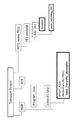
「送信装置の構成」
図2は、送信装置100の構成例を示している。この送信装置100は、制御部101と、LDRカメラ102Lと、HDRカメラ102Hと、LDR光電変換部103Lと、HDR光電変換部103Hと、ビデオエンコーダ104と、システムエンコーダ105と、送信部106を有している。制御部101は、CPU(Central Processing Unit)を備えて構成され、図示しないストレージに格納されている制御プログラムに基づいて、送信装置100の各部の動作を制御する。"Configuration of Transmitter"
FIG. 2 shows a configuration example of the
LDRカメラ102Lは、被写体を撮像して、LDR(Low Dynamic Range)画像データ(LDRビデオデータ)を出力する。このLDR画像データは、従来のLDR画像の白ピークの明るさに対して0%から100%のコントラスト比を持つ。HDRカメラ102Hは、LDRカメラ102Lの被写体と同一の被写体を撮像して、HDR(High Dynamic Range)画像データ(HDRビデオデータ)を出力する。このHDR画像データは、0〜100%*N、例えば0〜400%あるいは0〜800%などのコントラスト比を持つ。ここで、100%のレベルは、白の輝度値100cd/m**2に相当するものを前提とする場合がある。
The
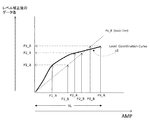
LDR光電変換部103Lは、カメラ102Lから得られるLDR画像データに対して、LDR画像用の光電変換特性(LDR OETFカーブ)を適用して、第1の伝送画像データV1を得る。図3のa1の曲線は、LDR OETFカーブの一例を示している。また、図4のa2の曲線は、LDR OETFカーブの他の一例を示している。HDR光電変換部103Hは、カメラ102Hから得られるHDR画像データに対して、HDR画像用の光電変換特性(HDR OETFカーブ)を適用して、第2の伝送画像データV2を得る。図3のb1の曲線は、HDR OETFカーブの一例を示している。また、図4のb2の曲線は、HDR OETFカーブの他の一例を示している。
The LDR
なお、図3、図4において、横軸は、LDR光電変換部103L、HDR光電変換部103Hの入力を示し、明るさ相対値[%]で表している。ブラックレベル(Black level)は、N*100:1のコントラスト比の最小値と一致するものである。受信側での表示の際に、この値を参照することができる。ピークブライトネス(Peak brightness)は、HDRのピークブライトネス(最大照度値)を指定し、相対値N*100の対象とする。受信機は、電光変換(EOTF)を行う際に、この値と、表示デバイス(表示部)の表示能力との間で必要な輝度調整を行うことができる。あるいは、最大のブライトネスレベルを指定する代わりに、明るさの中間レベルの値と、そのコントラスト比の値を受信側へ送ることで同様の効果を実現することも可能である。また、図3、図4において、縦軸は、LDR光電変換部103L、HDR光電変換部103Hの出力である振幅値(AMP)を示す。
3 and 4, the horizontal axis indicates the input of the LDR
ビデオエンコーダ104は、第1の伝送画像データV1および第2の伝送画像データV2をレイヤ分けして符号化し、各レイヤのピクチャの符号化画像データを持つビデオストリームVSを生成する。この場合、第1の伝送画像データV1をそのまま符号化して第1のレイヤの符号化画像データとする。また、この場合、第2の伝送画像データV2から第1の伝送画像データVD1を減算して差分画像データDVを得、この差分画像データDVを符号化して第2のレイヤの符号化画像データする。
The
ビデオエンコーダ104は、符号化効率を高めるために、差分画像データDVを得るとき、第1の伝送画像データにレベル調整を施し、第1の伝送画像データV1の値を第2の伝送画像データV2の値に近づける。この場合、詳細説明は後述するが、LDR OETFカーブとHDR OETFカーブとの関係から求められたレベル調整カーブ(Level Coordination Curve)に基づいて調整される。この際、ビデオエンコーダ104は、ビデオストリームのレイヤに、レベル調整の特性情報、つまりレベル調整カーブ情報を挿入する。
When the
ビデオエンコード104は、第1の伝送画像データV1および差分画像データDVの各ピクチャを複数の階層に分類して符号化する。この場合、第1の伝送画像データV1の各ピクチャの符号化画像データは下位階層に割り当てられ、差分画像データDVの各ピクチャの符号化画像データは上位階層に割り当てられる。そして、この場合、第1の伝送画像データV1の各ピクチャの符号化ピクチャタイプと、差分画像データDVの対応する各ピクチャの符号化ピクチャタイプが一致するように符号化される。 The video encode 104 classifies and encodes each picture of the first transmission image data V1 and the difference image data DV into a plurality of layers. In this case, the encoded image data of each picture of the first transmission image data V1 is allocated to the lower layer, and the encoded image data of each picture of the difference image data DV is allocated to the upper layer. In this case, the encoded picture type of each picture of the first transmission image data V1 is encoded so that the encoded picture type of each corresponding picture of the difference image data DV matches.
ビデオエンコーダ104は、各階層のピクチャの符号化画像データに、ピクチャ毎に、所属階層を識別するための階層識別情報を付加する。この実施の形態では、各ピクチャのNALユニット(nal_unit)のヘッダ部分に、階層識別子(temporal_id)を意味する“nuh_temporal_id_plus1”)が配置される。また、ビデオエンコーダ104は、各階層のピクチャの符号化画像データに、ピクチャ毎に、符号化レイヤを識別するためのレイヤ情報を付加する。この実施の形態では、各ピクチャのNALユニット(nal_unit)のヘッダ部分に、レイヤ情報としてレイヤ識別子(Layer_id)が配置される。
The
図5は、ビデオエンコーダ104で行われる階層符号化の一例を示している。この例は、0から5までの6階層に分類され、各階層のピクチャの画像データに対して符号化が施された例である。縦軸は階層を示している。第1の伝送画像データV1の各ピクチャは階層0から2の下位階層を構成し、差分画像データDVの各ピクチャは階層3から5の上位階層を構成する。
FIG. 5 shows an example of hierarchical encoding performed by the
階層0から5のピクチャの符号化画像データを構成するNALユニット(nal_unit)のヘッダ部分に配置されるtemporal_id(階層識別情報)として、それぞれ、0から5が設定される。横軸は表示順(POC:picture order of composition)を示し、左側は表示時刻が前で、右側は表示時刻が後になる。
0 to 5 are set as temporal_id (hierarchy identification information) arranged in the header portion of the NAL unit (nal_unit) constituting the encoded image data of the pictures of
図6(a)は、NALユニットヘッダの構造例(Syntax)を示し、図6(b)は、その構造例における主要なパラメータの内容(Semantics)を示している。「Forbidden_zero_bit」の1ビットフィールドは、0が必須である。「nal_unit_type」の6ビットフィールドは、NALユニットタイプを示す。 FIG. 6A shows a structure example (Syntax) of the NAL unit header, and FIG. 6B shows contents (Semantics) of main parameters in the structure example. In the 1-bit field of “Forbidden_zero_bit”, 0 is essential. A 6-bit field of “nal_unit_type” indicates a NAL unit type.
「nuh_layer_id」の6ビットフィールドは、レイヤ識別子(Layer_id)を示す。“0”は、temporal_id(階層識別情報)以外のレイヤ(layer)を設けないことを示す。“1”は、temporal_id(階層識別情報)以外のレイヤ(layer)として、ベースレイヤ(base layer)、つまり第1のレイヤに属することを示す。“2”は、temporal_id(階層識別情報)以外のレイヤ(layer)として、エンハンスレイヤ(enhance layer)、つまり第2のレイヤに属することを示す。「nuh_temporal_id_plus1」の3ビットフィールドは、temporal_idを示し、1を加えた値(1〜6)を示す。 A 6-bit field of “nuh_layer_id” indicates a layer identifier (Layer_id). “0” indicates that no layer other than temporal_id (hierarchy identification information) is provided. “1” indicates that the layer belongs to a base layer, that is, the first layer, as a layer other than temporal_id (hierarchy identification information). “2” indicates that the layer belongs to an enhancement layer, that is, the second layer, as a layer other than temporal_id (hierarchy identification information). A 3-bit field of “nuh_temporal_id_plus1” indicates temporal_id and indicates a value (1 to 6) obtained by adding 1.
図5に戻って、矩形枠のそれぞれがピクチャを示し、数字は、符号化されているピクチャの順、つまりエンコード順(受信側ではデコード順)を示している。「1」から「4」の4個のピクチャにより、第1の伝送画像データV1のあるサブ・ピクチャグループ(Sub Pictures Group )が構成されており、「1」はそのサブ・ピクチャグループの先頭のピクチャとなる。「0」は前のサブ・ピクチャグループのピクチャである。また、「5」から「8」の4個のピクチャにより、第1の伝送画像データV1の次のサブ・ピクチャグループ(Sub Pictures Group )が構成されており、「5」はそのサブ・ピクチャグループの先頭のピクチャとなる。ここで、「1」はIピクチャ(Intra picture)であり、「5」はPピクチャ(Uni-prediction picture)であり、その他はBピクチャ(Bi-prediction picture)である。 Returning to FIG. 5, each of the rectangular frames indicates a picture, and the number indicates the order of the encoded pictures, that is, the encoding order (decoding order on the receiving side). A sub picture group (Sub Pictures Group) having the first transmission image data V1 is composed of four pictures “1” to “4”, and “1” is the head of the sub picture group. It becomes a picture. “0” is a picture of the previous sub-picture group. Also, the next sub-picture group (Sub Pictures Group) of the first transmission image data V1 is composed of four pictures “5” to “8”, and “5” is the sub-picture group. The first picture of. Here, “1” is an I picture (Intra picture), “5” is a P picture (Uni-prediction picture), and the others are B pictures (Bi-prediction picture).
また、「1´」から「4´」の4個のピクチャにより、差分画像データDVのあるサブ・ピクチャグループ(Sub Pictures Group )が構成されており、「1´」はそのサブ・ピクチャグループの先頭のピクチャとなる。「0´」は前のサブ・ピクチャグループのピクチャである。また、「5´」から「8´」の4個のピクチャにより、差分画像データDVの次のサブ・ピクチャグループ(Sub Pictures Group )が構成されており、「5´」はそのサブ・ピクチャグループの先頭のピクチャとなる。ここで、「1´」はIピクチャ(Intra picture)であり、「5´」はPピクチャ(Uni-prediction picture)であり、その他はBピクチャ(Bi-prediction picture)である。 Further, a sub picture group (Sub Pictures Group) having difference image data DV is constituted by four pictures “1 ′” to “4 ′”, and “1 ′” is the sub picture group. This is the first picture. “0 ′” is the picture of the previous sub-picture group. Further, the next sub picture group (Sub Pictures Group) of the difference image data DV is constituted by four pictures “5 ′” to “8 ′”, and “5 ′” is the sub picture group. The first picture of. Here, “1 ′” is an I picture (Intra picture), “5 ′” is a P picture (Uni-prediction picture), and the others are B pictures (Bi-prediction picture).
図示のように、第1の伝送画像データV1の「1」から「8」のピクチャは、それぞれ、差動画像データDVの「1´」から「8´」のピクチャと対応しているが、第1の伝送画像データV1の各ピクチャの符号化ピクチャタイプと、差分画像データDVの対応する各ピクチャの符号化ピクチャタイプが一致するように符号化されている。 As shown in the figure, the pictures “1” to “8” of the first transmission image data V1 correspond to the pictures “1 ′” to “8 ′” of the differential image data DV, respectively. The encoded picture type of each picture of the first transmission image data V1 is encoded so that the encoded picture type of each corresponding picture of the difference image data DV matches.
実線矢印は、符号化におけるピクチャの参照関係を示している。例えば、「5」のピクチャは、Pピクチャであり、「1」のピクチャを参照して符号化される。また、「6」のピクチャは、Bピクチャであり、「1」、「5」のピクチャを参照して符号化される。同様に、その他のピクチャは、表示順で近くのピクチャを参照して符号化される。 A solid line arrow indicates a reference relationship of pictures in encoding. For example, the picture “5” is a P picture and is encoded with reference to the picture “1”. The picture “6” is a B picture and is encoded with reference to the pictures “1” and “5”. Similarly, other pictures are encoded with reference to nearby pictures in display order.
図7は、ビデオエンコーダ104の構成例を示している。ビデオエンコーダ104は、動き予測変換符号化/量子化部141と、エントロピー符号化部142と、レベル調整部143と、減算部144と、動き予測変換符号化/量子化部145と、エントロピー符号化部146と、ストリームパッキング部147を有している。
FIG. 7 shows a configuration example of the
動き予測変換符号化/量子化部141は、第1の伝送画像データV1に対して、動き予測変換符号化を行って時間軸データから周波数軸データに変換し、さらにこの周波数軸データに対して量子化を行って量子化データを得る。エントロピー符号化部142は、動き予測変換符号化/量子化部141で得られる量子化データに対して、エントロピー符号化を行って、第1のレイヤの符号化画像データCV1を得る。
The motion predictive transform coding /
レベル調整部143は、符号化効率を高めるために、第1の伝送画像データV1にレベル調整を施し、第1の伝送画像データV1の値を第2の伝送画像データV2の値に近づける。レベル調整部143は、LDR OETFカーブとHDR OETFカーブとの関係から求められたレベル調整カーブ(Level Coordination Curve)に基づいて、第1の伝送画像データのレベルを調整する。
The
レベル調整についてさらに説明する。図3のLDR OETFカーブおよびHDR OETFカーブを参照して説明する。レベル調整では、LDRの明るさ相対値(横軸の入力範囲)のPLの範囲内において、LDRのAMP値(第1の伝送画像データV1の値)をHDRのAMP値(第2の伝送画像データV2の値)に近づけるように、LDRのAMP値に補正をかける。この場合、補正対象のLDRのAMP値(第1の伝送画像データV1の値)であるPx_AをPx_Bにマッピングする。 The level adjustment will be further described. This will be described with reference to the LDR OETF curve and the HDR OETF curve in FIG. In the level adjustment, the LDR AMP value (value of the first transmission image data V1) is changed to the HDR AMP value (second transmission image) within the range of PL of the LDR brightness relative value (input range on the horizontal axis). The AMP value of the LDR is corrected so as to approach the value of the data V2. In this case, Px_A that is the AMP value of the LDR to be corrected (the value of the first transmission image data V1) is mapped to Px_B.
図8の曲線c1は、その際のマッピングカーブを示している。このマッピングカーブは、図3のLDR OETFカーブおよびHDR OETFカーブが使用された場合におけるレベル調整カーブを構成する。レベル調整部143は、このマッピングカーブに基づいて、LDRのAMP値(第1の伝送画像データV1の値)であるPx_AをPx_Bにマッピングし、第1の伝送画像データV1の値を第2の伝送画像データV2の値に近づける。
A curve c1 in FIG. 8 shows a mapping curve at that time. This mapping curve constitutes a level adjustment curve when the LDR OETF curve and the HDR OETF curve in FIG. 3 are used. Based on this mapping curve, the
なお、LDR OETFカーブおよびHDR OETFカーブが他の組み合わせであっても、同様にして、レベル調整カーブを構成するマッピングカーブを求めることができ、レベル調整部143は、そのマッピングカーブに基づいて、LDRのAMP値(第1の伝送画像データV1の値)であるPx_AをPx_Bにマッピングすることで、第1の伝送画像データV1の値を第2の伝送画像データV2の値に近づけることができる。例えば、図9の曲線c2は、図4のLDR OETFカーブおよびHDR OETFカーブが使用された場合におけるマッピングカーブを示している。
Even if the LDR OETF curve and the HDR OETF curve are in other combinations, the mapping curve constituting the level adjustment curve can be obtained in the same manner, and the
図7に戻って、減算部144は、第2の伝送画像データV2から、レベル調整部143でレベル調整された後の第1の伝送画像データV1を減算して、差分画像データDVを得る。なお、この差分画像データDVの生成に際し、差分情報が小さくなるよう、動き予測変換符号化/量子化部145と同様の、動きベクトルを利用した予測処理を行い、差分データと共に動きベクトルを伝送する。動き予測変換符号化/量子化部145は、この差分画像データDVに対して、動き予測変換符号化を行って時間軸データから周波数軸データに変換し、さらにこの周波数軸データに対して量子化を行って量子化データを得る。エントロピー符号化部146、動き予測変換符号化/量子化部145で得られる量子化データに対して、エントロピー符号化を行って、第2のレイヤの符号化画像データCV2を得る。
Returning to FIG. 7, the
ストリームパッキング部147は、第1のレイヤの符号化画像データCV1および第2のレイヤの符号化画像データCV2を含むビデオストリーム(ビデオエレメンタリストリーム)VSを生成する。この際、各ピクチャのNALユニット(nal_unit)のヘッダ部分に、階層識別子(temporal_id)を意味する“nuh_temporal_id_plus1”)が配置されると共に、レイヤ識別子(Layer_id)が配置される。また、この際、ビデオストリームのレイヤに、レベル調整の特性情報が挿入される。この特性情報は、例えば、予測画像を含めた表示アクセス単位であるGOP(Group Of Picture)単位で挿入される。
The
図2に戻って、システムエンコーダ105は、ビデオエンコーダ104で生成されたビデオストリームVSを含むトランスポートストリームTSを生成する。そして、送信部106は、このトランスポートストリームTSを、放送波あるいはネットのパケットに載せて、受信装置200に送信する。
Returning to FIG. 2, the
この際、システムエンコーダ105は、コンテナ(トランスポートストリーム)のレイヤに、各階層のピクチャの符号化画像データのレイヤを識別するためのレイヤ情報を挿入する。このレイヤ情報は、例えば、プログラム・マップ・テーブルの配下のビデオエレメンタリストリームループ中のデスクリプタに記述される。このレイヤ情報は、各レイヤに含まれる階層識別子(temporal_id)の値を示すものとされる。
At this time, the
図2に示す送信装置100の動作を簡単に説明する。LDRカメラ102Lで撮像されて得られたLDR画像データ(LDRビデオデータ)は、LDR光電変換部103Lに供給される。このLDR光電変換部103Lでは、このLDR画像データに対してLDR画像用の光電変換特性(LDR OETFカーブ)が適用されて、第1の伝送画像データV1が得られる。この第1の伝送画像データV1は、ビデオエンコーダ104に供給される。
The operation of the
また、HDRカメラ102Hで撮像されて得られたHDR画像データ(HDRビデオデータ)は、HDR光電変換部103Hに供給される。このHDR光電変換部103Hでは、このHDR画像データに対してHDR画像用の光電変換特性(LDR OETFカーブ)が適用されて、第2の伝送画像データV2が得られる。この第2の伝送画像データV2は、ビデオエンコーダ104に供給される。
Also, HDR image data (HDR video data) obtained by imaging with the
ビデオエンコーダ104では、第1の伝送画像データV1および第2の伝送画像データV2がレイヤ分けされて符号化され、各レイヤのピクチャの符号化画像を持つビデオストリームVSが生成される。この場合、第1の伝送画像データV1はそのまま符号化されて第1のレイヤの符号化画像データとされる。また、この場合、第2の伝送画像データV2から第1の伝送画像データVD1が減算されて得られた差分画像データDVが符号化されて第2のレイヤの符号化画像データとされる。
In the
ここで、符号化効率を高めるために、差分画像データDVを得るとき、第1の伝送画像データに対して、LDR OETFカーブとHDR OETFカーブとの関係から求められたレベル調整カーブ(マッピングカーブ)に基づいてレベル調整が施され、第1の伝送画像データV1の値が第2の伝送画像データV2の値に近づけられる。 Here, in order to increase the coding efficiency, when obtaining the difference image data DV, the level adjustment curve (mapping curve) obtained from the relationship between the LDR OETF curve and the HDR OETF curve with respect to the first transmission image data Based on the level adjustment, the value of the first transmission image data V1 is brought close to the value of the second transmission image data V2.
また、ビデオエンコーダ104では、各階層のピクチャの符号化画像データに、ピクチャ毎に、所属階層を識別するための階層識別情報が付加される。また、ビデオエンコーダ104では、各階層のピクチャの符号化画像データに、ピクチャ毎に、レイヤを識別するためのレイヤ情報が付加される。
Further, in the
ビデオエンコーダ104で生成されたビデオストリームVSは、システムエンコーダ105に供給される。このシステムエンコーダ105では、ビデオストリームを含むMPEG2のトランスポートストリームTSが生成される。この際、システムエンコーダ105では、コンテナ(トランスポートストリーム)のレイヤに、各階層のピクチャの符号化画像データのレイヤを識別するためのレイヤ情報が挿入される。このトランスポートストリームTSは、送信部106により、放送波あるいはネットのパケットに載せて、受信装置200に送信される。
The video stream VS generated by the
[レベル調整特性情報、レイヤ情報、TS構成]
上述したように、ビデオストリームのレイヤに、レベル調整特性情報が挿入される。例えば、符号化方式がHEVCである場合、このレベル調整特性情報は、アクセスユニット(AU)の“SEIs”の部分に、レベルアジャステング・SEIメッセージ(Level_Adjusting SEI message)として挿入される。[Level adjustment characteristic information, layer information, TS configuration]
As described above, the level adjustment characteristic information is inserted into the layer of the video stream. For example, when the encoding method is HEVC, this level adjustment characteristic information is inserted as a level adjusting / SEI message (Level_Adjusting SEI message) in the “SEIs” portion of the access unit (AU).
図10は、符号化方式がHEVCである場合におけるGOP(Group Of Pictures)の先頭のアクセスユニットを示している。HEVCの符号化方式の場合、画素データが符号化されているスライス(slices)の前にデコード用のSEIメッセージ群「Prefix_SEIs」が配置され、このスライス(slices)の後に表示用のSEIメッセージ群「Suffix_SEIs」が配置される。レベルアジャステング・SEIメッセージは、SEIメッセージ群「Suffix_SEIs」として配置される。 FIG. 10 shows the top access unit of GOP (Group Of Pictures) when the encoding method is HEVC. In the HEVC encoding method, a decoding SEI message group “Prefix_SEIs” is arranged before a slice (slices) in which pixel data is encoded, and a display SEI message group “ “Suffix_SEIs” is arranged. The level adjusting / SEI message is arranged as an SEI message group “Suffix_SEIs”.
図11(a)は、「Level_Adjusting SEI message」の構造例(Syntax)を示している。「uuid_iso_iec_11578」は、“ISO/IEC 11578:1996 AnnexA.”で示されるUUID値をもつ。「user_data_payload_byte」のフィールドに、「Level_Adjusting_SEI()」が挿入される。図11(b)は、「Level_Adjusting_SEI()」の構造例(Syntax)を示しており、この中に、レベル調整特性情報としての「Level_Adjusting_information_data()」が挿入される。「userdata_id」は、符号なし16ビットで示されるレベル調整特性情報の識別子である。「Level_Adjusting_SEI_length」の8ビットフィールドは、このフィールド以後の「Level_Adjusting_information_data()」のバイトサイズを示す。 FIG. 11A shows a structural example (Syntax) of “Level_Adjusting SEI message”. “Uuid_iso_iec_11578” has a UUID value indicated by “ISO / IEC 11578: 1996 Annex A.”. “Level_Adjusting_SEI ()” is inserted into the field of “user_data_payload_byte”. FIG. 11B shows a structure example (Syntax) of “Level_Adjusting_SEI ()”, and “Level_Adjusting_information_data ()” as level adjustment characteristic information is inserted therein. “Userdata_id” is an identifier of the level adjustment characteristic information indicated by 16 bits without a sign. An 8-bit field “Level_Adjusting_SEI_length” indicates the byte size of “Level_Adjusting_information_data ()” after this field.
図12は、「Level_Adjusting_information_data()」の構造例(Syntax)を示している。図13は、図12に示す構造例における各情報の内容(Semantics)を示している。「peak_brightness_level」の8ビットフィールドは、対象とするピークの明るさのレベルを示す。この場合、ピークの明るさのレベルは、peak_brightness_level * 100 (cd/m**2)となる。 FIG. 12 illustrates a structure example (Syntax) of “Level_Adjusting_information_data ()”. FIG. 13 shows the contents (Semantics) of each piece of information in the structural example shown in FIG. The 8-bit field of “peak_brightness_level” indicates the brightness level of the target peak. In this case, the peak brightness level is peak_brightness_level * 100 (cd / m ** 2).
「Contrast_ratio」の8ビットフィールドは、0からpeak_brightness_level までのダイナミックレンジを表す。この場合、黒レベルの明るさは、peak_brightness_level * ( 1 / (black_level * 100) )となる。“1”は、peak_brightness_level の 1/100 のレベルであることを示す。“4”は、peak_brightness_level の 1/400 のレベルであることを示す。“16”は、peak_brightness_level の 1/1600 のレベルであることを示す。“64”は、peak_brightness_level の 1/6400 のレベルであることを示す。さらに“128”は、peak_brightness_level の 1/12800 のレベルであることを示す。 An 8-bit field of “Contrast_ratio” represents a dynamic range from 0 to peak_brightness_level. In this case, the brightness of the black level is peak_brightness_level * (1 / (black_level * 100)). “1” indicates that the level is 1/100 of peak_brightness_level. “4” indicates that the level is 1/400 of peak_brightness_level. “16” indicates that the level is 1/1600 of peak_brightness_level. “64” indicates that the level is 1/6400 of peak_brightness_level. Furthermore, “128” indicates that the level is 1/12800 of peak_brightness_level.
「coded_bit_extension_minus1」の4ビットフィールドは、伝送する画素のコンポーネント(component)あたりのビット(bit)幅の拡張を示す。“0”は、1ビット拡張(8bit + 1bit = 9bits)を示す。“1”は、2ビット 拡張(8bit + 2bit = 10bits)を示す。“2”は、3ビット拡張(8bit + 3bit = 11bits)を示す。“3”は、4ビット拡張 (8bit + 4bit = 12bits)を示す。「level_adjust [i]」の16ビットフィールドは、入力iの補正値を符号付きの値で示す。 A 4-bit field of “coded_bit_extension_minus1” indicates an extension of a bit width per component of a pixel to be transmitted. “0” indicates 1-bit extension (8 bits + 1 bit = 9 bits). “1” indicates 2-bit extension (8 bits + 2 bits = 10 bits). “2” indicates a 3-bit extension (8 bits + 3 bits = 11 bits). “3” indicates a 4-bit extension (8 bits + 4 bits = 12 bits). A 16-bit field of “level_adjust [i]” indicates a correction value of the input i as a signed value.
また、上述したように、コンテナ(トランスポートストリーム)のレイヤに、各階層のピクチャの符号化画像データのレイヤを識別するためのレイヤ情報が挿入される。この実施の形態においては、例えば、PMT(Program Map Table)の配下に、レイヤ情報を含む記述子であるレイヤ・ヒエラルキー・デスクリプタ(Layer_hierarchy descriptor)が挿入される。 Further, as described above, layer information for identifying the layer of the encoded image data of the picture of each layer is inserted into the layer of the container (transport stream). In this embodiment, for example, a layer hierarchy descriptor (Layer_hierarchy descriptor) that is a descriptor including layer information is inserted under a PMT (Program Map Table).
図14は、このレイヤ・ヒエラルキー・デスクリプタの構造例(Syntax)を示している。図15は、図14に示す構造例における各情報の内容(Semantics)を示している。「Layer_hierarchy_tag」の8ビットフィールドは、デスクリプタタイプを示し、ここでは、レイヤ・ヒエラルキー・デスクリプタであることを示す。「Layer_hierarchy_length」の8ビットフィールドは、デスクリプタの長さ(サイズ)を示し、デスクリプタの長さとして以降のバイト数を示す。 FIG. 14 shows a structural example (Syntax) of this layer hierarchy descriptor. FIG. 15 shows the contents (Semantics) of each piece of information in the structural example shown in FIG. An 8-bit field of “Layer_hierarchy_tag” indicates a descriptor type, and here indicates a layer hierarchy descriptor. The 8-bit field of “Layer_hierarchy_length” indicates the length (size) of the descriptor, and indicates the number of subsequent bytes as the descriptor length.
「Layer_id_for _full_decoding」の3ビットフィールドは、対応するビデオストリームをフルにデコードする場合の最大テンポラルID(temporal_id)を示す。「Layer_id_for _base_decoding」の3ビットフィールドは、対応するビデオストリームのベースレイヤ(第1のレイヤ)部分をデコードする場合の最大テンポラルID(temporal_id)を示す。「NAL_layer_signaling」の1ビットフィールドは、NAL unit header に、nuh_layer_idによるレイヤシグナリングが行われることを示す。 A 3-bit field of “Layer_id_for_full_decoding” indicates a maximum temporal ID (temporal_id) when the corresponding video stream is fully decoded. A 3-bit field of “Layer_id_for_base_decoding” indicates a maximum temporal ID (temporal_id) when the base layer (first layer) portion of the corresponding video stream is decoded. A 1-bit field of “NAL_layer_signaling” indicates that layer signaling by nuh_layer_id is performed in the NAL unit header.
図16は、トランスポートストリームTSの構成例を示している。トランスポートストリームTSには、ビデオエレメンタリストリームのPESパケット「PID1:video PES1」が含まれている。このビデオエレメンタリストリームに、上述のレベルアジャステング・SEIメッセージ(Level_Adjusting SEI message)が挿入されている。また、NALユニットのヘッダ部分に、階層識別子(temporal_id)を意味する“nuh_temporal_id_plus1”)が配置されていると共に、レイヤ情報としてレイヤ識別子(Layer_id)が配置されている。 FIG. 16 illustrates a configuration example of the transport stream TS. The transport stream TS includes a PES packet “PID1: video PES1” of the video elementary stream. The level adjusting and SEI message (Level_Adjusting SEI message) described above is inserted in this video elementary stream. In addition, in the header portion of the NAL unit, “nuh_temporal_id_plus1” meaning a hierarchy identifier (temporal_id) is arranged, and a layer identifier (Layer_id) is arranged as layer information.
また、トランスポートストリームTSには、PSI(Program Specific Information)として、PMT(Program Map Table)が含まれている。PSIは、トランスポートストリームに含まれる各エレメンタリストリームがどのプログラムに属しているかを記した情報である。また、トランスポートストリームTSには、イベント(番組)単位の管理を行うSI(Serviced Information)としてのEIT(Event Information Table)が含まれている。 In addition, the transport stream TS includes a PMT (Program Map Table) as PSI (Program Specific Information). PSI is information describing to which program each elementary stream included in the transport stream belongs. Further, the transport stream TS includes an EIT (Event Information Table) as SI (Serviced Information) for managing an event (program) unit.
PMTには、各エレメンタリストリームに関連した情報を持つエレメンタリ・ループが存在する。この構成例では、ビデオエレメンタリ・ループ(Video ES loop)が存在する。このビデオエレメンタリ・ループには、上述のビデオエレメンタリストリームに対応して、ストリームタイプ、パケット識別子(PID)等の情報が配置されると共に、そのビデオエレメンタリストリームに関連する情報を記述するデスクリプタも配置される。このPMTのビデオエレメンタリ・ループ(Video ES loop)の配下に、上述のレイヤ・ヒエラルキー・デスクリプタ(Layer_hierarchy descriptor)が配置される。 In the PMT, there is an elementary loop having information related to each elementary stream. In this configuration example, a video elementary loop (Video ES loop) exists. In this video elementary loop, information such as a stream type and a packet identifier (PID) is arranged corresponding to the video elementary stream described above, and a descriptor describing information related to the video elementary stream. Also arranged. The above-described layer hierarchy descriptor (Layer_hierarchy descriptor) is arranged under the video elementary loop (Video ES loop) of the PMT.
「受信装置の構成」
図17は、受信装置200の構成例を示している。受信装置200は、制御部201と、受信部202と、システムデコーダ203と、ビデオデコーダ204と、切り替え部205と、LDR電光変換部206Lと、HDR電光変換部206Hと、表示部(表示デバイス)207を有している。制御部201は、CPU(Central Processing Unit)を備えて構成され、図示しないストレージに格納されている制御プログラムに基づいて、受信装置200の各部の動作を制御する。"Receiver configuration"
FIG. 17 illustrates a configuration example of the receiving
受信部202は、送信装置100から放送波あるいはネットのパケットに載せて送られてくるトランスポートストリームTSを受信する。システムデコーダ203は、このトランスポートストリームTSからビデオストリーム(エレメンタリストリーム)VSを抽出する。また、システムデコーダ203は、コンテナ(トランスポートストリーム)のレイヤに挿入されている種々の情報を抽出し、制御部201に送る。この情報には、上述したレイヤ・ヒエラルキー・デスクリプタも含まれる。
The
ビデオデコーダ204は、システムデコーダ203で抽出されるビデオストリームVSに対して復号化処理などを行って、例えば、表示部207の表示能力に応じて、第1の伝送ビデオデータV1あるいは第2の伝送ビデオデータV2を選択的に出力する。つまり、表示部207がLDR画像の表示能力を持つ場合、ビデオデコーダ204は、第1の伝送画像データV1を出力する。一方、表示部207がHDR画像の表示能力を持つ場合、ビデオデコーダ204は、第2の伝送画像データV2を出力する。
The
また、ビデオデコーダ204は、ビデオストリームVSに挿入されているSEIメッセージを抽出し、制御部201に送る。このSEIメッセージには、上述したレベル調整特性情報を持つレベルアジャステング・SEIメッセージも含まれる。
Also, the
図18は、ビデオデコーダ204の構成例を示している。ビデオデコーダ204は、ストリームアンパッキング部241と、エントロピー復号化部242と、逆量子化/動き補償復号化部243と、エントロピー復号化部244と、逆量子化/動き補償復号化部245と、レベル調整部246と、加算部247と、切り替え部248を有している。
FIG. 18 shows a configuration example of the
ストリームアンパッキング部241は、ビデオストリームVSから、第1のレイヤの符号化画像データCV1と第2のレイヤの符号化画像データCV2を分けて取り出す。この場合、ストリームアンパッキン部241は、ビデオストリームのレイヤあるいはコンテナのレイヤに挿入されている、各レイヤのピクチャの符号化画像データのレイヤ情報に基づいて、第1のレイヤの符号化画像データCV1と第2のレイヤの符号化画像データCV2を分ける。受信機がLDR表示を行う際は、ストリームアンパッキング部241からはCV1のみをエントロピー復号化部242へ送り、一方、受信機がHDR表示を行う際は、ストリームアンパッキング部241からはCV1をエントロピー復号化部242へ送ると共に、CV2をエントロピー復号化部244へ送る。
The
この場合、ストリームアンパッキング部241は、レイヤ・ヒエラルキー・デスクリプタ(図14参照)の「NAL_layer_signaling」の1ビットフィールドに基づき、“方法A”あるいは“方法B”を選択して、第1のレイヤの符号化画像データCV1と第2のレイヤの符号化画像データCV2を分ける。
In this case, the
例えば、「NAL_layer_signaling」の1ビットフィールドが“1”であってNAL unit header にnuh_layer_idによるレイヤシグナリングが行われることを示すときは、“方法A”を採用する。このとき、NALユニットの解析(parsing)で取得される「nuh_layer_id」、「nuh_temporal_id_plus1」は、図19の“方法A”側に示す状態となっている。 For example, when the 1-bit field of “NAL_layer_signaling” is “1” and indicates that layer signaling by nuh_layer_id is performed in the NAL unit header, “method A” is adopted. At this time, “nuh_layer_id” and “nuh_temporal_id_plus1” acquired by parsing the NAL unit are in the state shown on the “method A” side in FIG.
つまり、「nuh_temporal_id_plus1」が0,1,2である第1のレイヤ(ベースレイヤ)の各ピクチャにおいて、「nuh_layer_id」は1,1,1なる。一方、「nuh_temporal_id_plus1」が3,4,5である第2のレイヤ(エンハンスレイヤ)の各ピクチャにおいて、「nuh_layer_id」は2,2,2なる。従って、この“方法A”では、「nuh_layer_id」の値により、第1のレイヤの符号化画像データCV1と第2のレイヤの符号化画像データCV2を分ける。 That is, in each picture of the first layer (base layer) where “nuh_temporal_id_plus1” is 0, 1, 2, “nuh_layer_id” is 1,1,1. On the other hand, in each picture of the second layer (enhancement layer) where “nuh_temporal_id_plus1” is 3, 4, and 5, “nuh_layer_id” is 2, 2, and 2. Therefore, in this “method A”, the encoded image data CV1 of the first layer and the encoded image data CV2 of the second layer are separated by the value of “nuh_layer_id”.
一方、「NAL_layer_signaling」の1ビットフィールドが“0”であってNAL unit header にnuh_layer_idによるレイヤシグナリングが行われないことを示すときは、“方法B”を採用する。このとき、NALユニットの解析(parsing)で取得される「nuh_layer_id」、「nuh_temporal_id_plus1」は、図19の“方法B”側に示す状態となっている。 On the other hand, when the 1-bit field of “NAL_layer_signaling” is “0” and indicates that layer signaling by nuh_layer_id is not performed in the NAL unit header, “method B” is adopted. At this time, “nuh_layer_id” and “nuh_temporal_id_plus1” acquired by parsing the NAL unit are in the state shown on the “method B” side in FIG.
つまり、「nuh_temporal_id_plus1」が0,1,2である第1のレイヤ(ベースレイヤ)の各ピクチャにおいて、「nuh_layer_id」は0,0,0となる。一方、「nuh_temporal_id_plus1」が3,4,5である第2のレイヤ(ベースレイヤ)の各ピクチャにおいても、「nuh_layer_id」は0,0,0となる。そのため、「nuh_layer_id」の値により、第1のレイヤの符号化画像データCV1と第2のレイヤの符号化画像データCV2を分けることができない。 That is, in each picture of the first layer (base layer) where “nuh_temporal_id_plus1” is 0, 1, 2, “nuh_layer_id” is 0, 0, 0. On the other hand, in each picture of the second layer (base layer) where “nuh_temporal_id_plus1” is 3, 4, and 5, “nuh_layer_id” is 0, 0, 0. Therefore, the encoded image data CV1 of the first layer and the encoded image data CV2 of the second layer cannot be separated by the value of “nuh_layer_id”.
しかし、レイヤ・ヒエラルキー・デスクリプタには、「Layer_id_for _full_decoding」、「Layer_id_for _base_decoding」が存在する。上述したように、「Layer_id_for _full_decoding」の3ビットフィールドは、対応するビデオストリームをフルにデコードする場合の最大テンポラルID(temporal_id)を示す。また、「Layer_id_for _base_decoding」の3ビットフィールドは、対応するビデオストリームのベースレイヤ(第1のレイヤ)部分をデコードする場合の最大テンポラルID(temporal_id)を示す。従って、この“方法B”では、「Layer_id_for _full_decoding」、「Layer_id_for _base_decoding」の値と、「nuh_temporal_id_plus1」の値により、第1のレイヤの符号化画像データCV1と第2のレイヤの符号化画像データCV2を分ける。 However, “Layer_id_for_full_decoding” and “Layer_id_for_base_decoding” exist in the layer hierarchy descriptor. As described above, the 3-bit field of “Layer_id_for_full_decoding” indicates the maximum temporal ID (temporal_id) when the corresponding video stream is fully decoded. A 3-bit field of “Layer_id_for_base_decoding” indicates a maximum temporal ID (temporal_id) when the base layer (first layer) portion of the corresponding video stream is decoded. Therefore, in this “method B”, the encoded image data CV1 of the first layer and the encoded image data CV2 of the second layer are determined based on the values of “Layer_id_for_full_decoding”, “Layer_id_for_base_decoding”, and “nuh_temporal_id_plus1”. Separate.
また、図18に戻って、ストリームアンパッキング部241は、ビデオストリームVSに挿入されているSEIメッセージを抽出し、制御部201に送る。このSEIメッセージには、上述したレベル調整特性情報を持つレベルアジャステング・SEIメッセージも含まれている。
Returning to FIG. 18, the
エントロピー復号化部242は、ストリームアンパッキング部241で取り出される第1のレイヤの符号化画像データCV1に対して、エントロピー復号化を行って量子化データを得る。逆量子化/動き補償変換復号化部243は、その量子化データに逆量子化を施し、さらに動き補償変換復号化を行って周波数軸データから時間軸データに変換して、第1の伝送画像データV1を得る。
The
エントロピー復号化部244は、ストリームアンパッキング部241で取り出される第2のレイヤの符号化画像データCV2に対して、エントロピー復号化を行って量子化データを得る。逆量子化/動き補償変換復号化部245は、その量子化データに逆量子化を施し、さらに動き補償変換復号化を行って周波数軸データから時間軸データに変換して、差分画像データDVを得る。
The
レベル調整部246は、第1の伝送画像データV1にレベル調整を施す。この場合、レベル調整部246は、ストリームアンパッキング部241で抽出されたレベルアジャステング・SEIメッセージに含まれているレベル調整特性情報に基づいて、上述した送信装置100のビデオエンコーダ104のレベル調整部143におけると同様のマッピングカーブ(レベル調整カーブ)を用いて補正をかける。
The
加算部247は、差分画像データDVに、レベル調整部246でレベル調整された後の第1の伝送画像データV1を加算して、第2の伝送画像データV2を得る。なお、加算の際は、レイヤ間の予測ベクトルを利用した予測・補償が行われる。切り替え部248は、制御部201の制御のもと、例えば、表示部(表示デバイス)207の表示能力に応じて、第1の伝送画像データV1または第2の伝送画像データV2を選択的に出力する。つまり、表示部207がLDR画像の表示能力を持つ場合、切り替え部248は第1の伝送画像データV1を出力する。一方、表示部207がHDR画像の表示能力を持つ場合、切り替え部248は第2の伝送画像データV2を出力する。
The
図17に戻って、切り替え部205は、ビデオデコーダ204の出力画像データを、LDR電光変換部206LまたはHDR電光変換部206Hに、選択的に送る。この場合、切り替え部205は、ビデオデコーダ204の出力画像データが第1の伝送画像データV1である場合には、その第1の伝送画像データV1をLDR電光変換部206Lに送る。一方、切り替え部205は、ビデオデコーダ204の出力画像データが第2の伝送画像データV2である場合には、その第2の伝送画像データV2をHDR電光変換部206Hに送る。
Returning to FIG. 17, the
LDR電光変換部206Lは、第1の伝送画像データV1に、上述した送信装置100におけるLDR光電変換部103Lにおける光電変換特性とは逆特性の電光変換を施して、LDR画像を表示するための出力画像データを得る。また、HDR電光変換部206Hは、第2の伝送画像データV2に、上述した送信装置100におけるHDR光電変換部103Hにおける光電変換特性とは逆特性の電光変換を施して、HDR画像を表示するための出力画像データを得る。
The LDR electro-
表示部207は、例えば、LCD(Liquid Crystal Display)、有機EL(Organic Electro-Luminescence)パネル等で構成されている。表示部207は、LDR画像の表示能力を持つ場合、LDR電光変換部206Lで得られる出力画像データによるLDR画像を表示する。一方、表示部207は、HDR画像の表示能力を持つ場合、HDR電光変換部206Hで得られる出力画像データによるHDR画像を表示する。なお、この表示部207は、受信装置200に接続される外部機器であってもよい。
The
図17に示す受信装置200の動作を簡単に説明する。受信部202では、送信装置100から放送波あるいはネットのパケットに載せて送られてくるトランスポートストリームTSが受信される。このトランスポートストリームTSは、システムデコーダ203に供給される。システムデコーダ203では、このトランスポートストリームTSからビデオストリーム(エレメンタリストリーム)VSが抽出される。また、システムデコーダ203では、コンテナ(トランスポートストリーム)のレイヤに挿入されている種々の情報が抽出され、制御部201に送られる。この情報には、上述したレイヤ・ヒエラルキー・デスクリプタも含まれる。
The operation of the receiving
システムデコーダ203で抽出されたビデオストリームVSは、ビデオデコーダ204に供給される。このビデオストリームVSには、第1の伝送画像データV1が符号化されてなる第1のレイヤの符号化画像データCV1と、第2の伝送画像データV2から第1の伝送画像データV1を減算して得られた差分画像データDVが符号化されてなる第2のレイヤの符号化画像データCV2が含まれている。
The video stream VS extracted by the
ビデオデコーダ204では、ビデオストリームのレイヤあるいはコンテナのレイヤに挿入されている、各レイヤのピクチャの符号化画像データのレイヤ情報に基づいて、ビデオストリームVSから、第1のレイヤの符号化画像データCV1と第2のレイヤの符号化画像データCV2が分けて取り出される。
In the
そして、ビデオデコーダ204では、第1のレイヤの符号化画像データCV1が復号化されて第1の伝送ビデオデータV1が得られる。また、ビデオデコーダ204では、第2のレイヤの符号化画像データCV2が復号化されて得られた差分画像データDVに第1の伝送画像データV1が加算されて第2の伝送画像データV2が得られる。ここで、差分画像データDVに加算される第1の伝送画像データV1に対して、レベルアジャステング・SEIメッセージに含まれているレベル調整特性情報に基づいて、レベル調整が施される。
The
ビデオデコーダ204の出力画像データが第1の伝送画像データV1であるとき、この第1の伝送画像データV1は切り替え部205を介してLDR電光変換部206Lに供給される。このLDR電光変換部206Lでは、第1の伝送画像データV1に、上述した送信装置100における光電変換とは逆特性の電光変換が施されて、LDR画像を表示するための出力画像データが得られる。この出力画像データは表示部207に送られ、この表示部207に、LDR画像が表示される。
When the output image data of the
一方、ビデオデコーダ204の出力画像データが第2の伝送画像データV2であるとき、この第2の伝送画像データV2は切り替え部205を介してHDR電光変換部206Hに供給される。このHDR電光変換部206Hでは、第2の伝送画像データV2に、上述した送信装置100における光電変換とは逆特性の電光変換が施されて、HDR画像を表示するための出力画像データが得られる。この出力画像データは表示部207に送られ、この表示部207に、HDR画像が表示される。
On the other hand, when the output image data of the
上述したように、図1に示す送受信システム10においては、LDR画像データに光電変換を施して得られた第1の伝送ビデオデータとHDR画像データに光電変換を施して得られた第2の伝送ビデオデータとをレイヤ分けして符号化し、各レイヤのピクチャの符号化画像データを持つビデオストリームを含むコンテナを送信するものである。したがって、HDR画像データおよびLDR画像データの双方を良好に送信することが可能となる。
As described above, in the transmission /
また、図1に示す送受信システム10においては、第2の伝送ビデオデータから第1の伝送画像データを減算して差分画像データを得、第1の伝送画像データを符号化して第1のレイヤの符号化画像データとし、差分画像データを符号化して第2のレイヤの符号化画像データとするものである。そのため、符号化効率の向上が可能となる。
In the transmission /
また、図1に示す送受信システム10においては、第1の伝送画像データの各ピクチャの符号化ピクチャタイプと、差分画像データの対応する各ピクチャの符号化ピクチャタイプを一致させるものである。そのため、受信側では、第1のレイヤの符号化画像データの各ピクチャの復号化と第2のレイヤの符号化画像データの対応する各ピクチャの復号化とを同じタイミングで進めることが可能となり、第2の伝送画像データを得るためのデコード遅延を小さく抑えることが可能となる。
In the transmission /
また、図1に示す送受信システム10においては、各レイヤのピクチャの符号化画像データのレイヤ情報をビデオストリームのレイヤまたはコンテナのレイヤに挿入して送信するものである。そのため、受信側では、ビデオストリームから各レイヤのピクチャの符号化画像データを取り出すことが容易となる。
In the transmission /
また、図1に示す送受信システム10においては、差分画像データを得るとき、第1の伝送画像データにレベル調整を施し、第2の伝送画像データに近づけるものである。そのため、差分画像データの値を小さくでき、符号化効率をより高めることが可能となる。
In addition, in the transmission /
また、図1に示す送受信システム10においては、ビデオストリームのレイヤに、レベル調整の特性情報を挿入して送信するものである。そのため、受信側では、このレベル調整の特性情報に基づいて第1の伝送画像データのレベル調整を行った後に差分画像データに加算することで、第2の伝送画像データを良好に得ることが可能となる。
Further, in the transmission /
<2.変形例>
なお、上述実施の形態においては、第2の伝送画像データV2からレベル調整された第1の伝送画像データV1を減算して得られた差分画像データDVを符号化して第2のレイヤの符号化画像データCV2とする例を示した。しかし、(1)レベル調整された第2の伝送画像データV2から第1の伝送画像データV1を減算して得られた差分画像データDVを符号化して第2のレイヤの符号化画像データCV2とすることも考えられる。また、(2)第2の伝送画像データV2そのものを符号化して第2のレイヤの符号化画像データCV2とすることも考えられる。<2. Modification>
In the above embodiment, the difference image data DV obtained by subtracting the level-adjusted first transmission image data V1 from the second transmission image data V2 is encoded to encode the second layer. An example of image data CV2 is shown. However, (1) the difference image data DV obtained by subtracting the first transmission image data V1 from the second transmission image data V2 whose level has been adjusted is encoded to obtain the encoded image data CV2 of the second layer. It is also possible to do. It is also conceivable that (2) the second transmission image data V2 itself is encoded to be encoded image data CV2 of the second layer.
図20は、上述の(1)、(2)に対応したビデオエンコーダ104Aの構成例を示している。この図20において、図7と対応する部分には同一符号を付し、適宜、その詳細説明を省略する。レベル調整部143は、第2の伝送画像データV2にレベル調整を施し、第2の伝送画像データV2の値を第1の伝送画像データV1の値に近づける。減算部144は、レベル調整された第2の伝送画像データV2から第1の伝送画像データV1を減算して差分画像データDVを得る。なお、減算の際は、レイヤ間の予測ベクトルを利用した予測・補償が行われる。
FIG. 20 shows a configuration example of the
切り替え部148は、第2の画像データV2または差分画像データDVを選択的に、動き予測変換符号化/量子化部145に送る。ここで、差分画像データDVが選択された場合、第2のレイヤの符号化画像データCV2は、レベル調整された第2の伝送画像データV2から第1の伝送画像データV1を減算して得られた差分画像データDVを符号したものとなる。一方、第2の画像データV2が選択された場合、第2のレイヤの符号化画像データCV2は、第2の伝送画像データV2そのものを符号化したものとなる。
The
図21は、図20のビデオエンコーダ104Aに対応したビデオデコーダ204Aの構成例を示している。この図21において、図18と対応する部分には同一符号を付し、適宜、その詳細説明を省略する。逆量子化/動き補償変換復号化部245は、送信側から送られてくる第2のレイヤの符号化画像データCV2が差分画像データDVを符号化したものである場合、その差分画像データDVを出力する。
FIG. 21 shows a configuration example of a
この場合、加算部247は、その差分画像データDVと第1の伝送画像データV1を加算する。なお、加算の際は、レイヤ間の予測ベクトルを利用した予測・補償が行われる。そして、レベル調整部246は、その加算データに、上述のビデオエンコーダ204Aにおけるレベル調整部143とは逆のレベル調整を施し、第2の伝送画像データV2を得る。そして、この場合、切り替え部249は、レベル調整部246から得られる第2の伝送画像データV2を出力とするように切り替える。
In this case, the adding
一方、逆量子化/動き補償変換復号化部245は、送信側から送られてくる第2のレイヤの符号化画像データCV2が第2の伝送画像データV2を符号化したものである場合、その第2の伝送画像データV2を出力する。そして、この場合、切り替え部249は、その第2の伝送画像データV2を出力とするように切り替える。
On the other hand, the inverse quantization / motion compensation
また、上述実施の形態においては、第1の伝送画像データV1の各ピクチャの符号化ピクチャタイプと差分画像データDVの対応する各ピクチャの符号化ピクチャタイプを一致させる例を示した(図5参照)。しかし、本技術は、符号化ピクチャタイプを一致させない場合にも適用できる。 Further, in the above-described embodiment, an example has been shown in which the encoded picture type of each picture of the first transmission image data V1 is matched with the encoded picture type of each corresponding picture of the difference image data DV (see FIG. 5). ). However, the present technology can also be applied when the encoded picture types are not matched.
図22は、その場合における階層符号化の一例を示している。この例は、0から3までの4階層に分類され、各階層のピクチャの画像データに対して符号化が施された例である。縦軸は階層を示している。第1の伝送画像データV1の各ピクチャは階層0から2の下位階層を構成し、差分画像データDVの各ピクチャは階層3の上位階層を構成する。
FIG. 22 shows an example of hierarchical encoding in that case. In this example, the image data is classified into four layers from 0 to 3, and image data of pictures in each layer is encoded. The vertical axis represents the hierarchy. Each picture of the first transmission image data V1 constitutes a lower hierarchy of the
階層0から3のピクチャの符号化画像データを構成するNALユニット(nal_unit)のヘッダ部分に配置されるtemporal_id(階層識別情報)として、それぞれ、0から3が設定される。横軸は表示順(POC:picture order of composition)を示し、左側は表示時刻が前で、右側は表示時刻が後になる。矩形枠のそれぞれがピクチャを示し、数字は、符号化されているピクチャの順、つまりエンコード順(受信側ではデコード順)を示している。
0 to 3 are set as temporal_id (hierarchy identification information) arranged in the header portion of the NAL unit (nal_unit) constituting the encoded image data of the pictures of
また、上述実施の形態においては、トランスポートストリームTSに、第1のレイヤ(ベースレイヤ)および第2のレイヤ(エンハンスレイヤ)の各ピクチャの符号化画像データを持つ一つのビデオストリームVSが含まれる例を示した。しかし、トランスポートストリームTSに、第1のレイヤ(ベースレイヤ)の各ピクチャの符号化画像データを持つビデオストリームと、第2のレイヤ(エンハンスレイヤ)の各ピクチャの符号化画像データを持つビデオストリームの2つが含まれるようにしてもよい。 In the above embodiment, the transport stream TS includes one video stream VS having encoded image data of each picture of the first layer (base layer) and the second layer (enhancement layer). An example is shown. However, the transport stream TS includes a video stream having encoded image data of each picture in the first layer (base layer) and a video stream having encoded image data of each picture in the second layer (enhancement layer). These two may be included.
また、本技術は、以下のような構成を取ることもできる。
(1)従来のLDR画像の白ピークの明るさに対して0%から100%のコントラスト比を持つ第1の入力画像データに光電変換を施して得られた第1の伝送画像データおよび従来の白ピークの明るさを越える0%から100%*N(Nは1より大きい数)のコントラスト比を持つ第2の入力画像データに光電変換を施して得られた第2の伝送画像データをレイヤ分けして符号化し、各レイヤのピクチャの符号化画像データを持つビデオストリームを生成する画像符号化部と、
上記ビデオストリームを含む所定フォーマットのコンテナを送信する送信部を備える
送信装置。
(2)上記画像符号化部は、
上記第2の伝送画像データと上記第1の伝送画像データとの間で減算処理を行って差分画像データを得、
上記第1の伝送画像データを符号化して第1のレイヤの符号化画像データとし、上記差分画像データを符号化して第2のレイヤの符号化画像データとする
前記(1)に記載の送信装置。
(3)上記画像符号化部は、
上記減算処理を行って上記差分画像データを得るとき、上記第1の伝送画像データまたは上記第2の伝送画像データにレベル調整を施す
前記(2)に記載の送信装置。
(4)上記ビデオストリームのレイヤに、上記レベル調整の特性情報、および/または、明るさのレベル情報とコントラスト情報を挿入する情報挿入部をさらに備える
前記(3)に記載の送信装置。
(5)上記画像符号化部は、
上記第1の伝送画像データの各ピクチャの符号化ピクチャタイプと、上記差分画像データの対応する各ピクチャの符号化ピクチャタイプを一致させる
前記(2)から(4)のいずれかに記載の送信装置。
(6)上記画像符号化部は、
上記第1の伝送画像データを符号化して第1のレイヤの符号化画像データとし、上記第2の伝送画像データを符号化して第2のレイヤの符号化画像データとする
前記(1)に記載の送信装置。
(7)上記各レイヤのピクチャの符号化画像データのレイヤ情報を上記ビデオストリームのレイヤまたは上記コンテナのレイヤに挿入するレイヤ情報挿入部をさらに備える
前記(1)から(6)のいずれかに記載の送信装置。
(8)上記レイヤ情報挿入部は、
上記レイヤ情報を上記ビデオストリームのレイヤに挿入する場合、該レイヤ情報をNALユニットのヘッダに挿入する
前記(7)に記載の送信装置。
(9)上記コンテナのレイヤに挿入されるレイヤ情報は、各レイヤに対応するテンポラルIDの値を示す
前記(7)に記載の送信装置。
(10)従来のLDR画像の白ピークの明るさに対して0%から100%のコントラスト比を持つ第1の入力画像データに光電変換を施して得られた第1の伝送画像データおよび従来の白ピークの明るさを越える0%から100%*N(Nは1より大きい数)のコントラスト比を持つ第2の入力画像データに光電変換を施して得られた第2の伝送画像データをレイヤ分けして符号化し、各レイヤのピクチャの符号化画像データを持つビデオストリームを生成する画像符号化ステップと、
送信部により、上記ビデオストリームを含む所定フォーマットのコンテナを送信する送信ステップを有する
送信方法。
(11)第1の伝送画像データおよび第2の伝送画像データがレイヤ分けされて符号化されてなる各レイヤのピクチャの符号化画像データを持つビデオストリームを含むコンテナを受信する受信部を備え、
上記第1の伝送画像データは、従来のLDR画像の白ピークの明るさに対して0%から100%のコントラスト比を持つ第1の入力画像データに光電変換を施して得られたものであり、
上記第2の伝送画像データは、従来の白ピークの明るさを越える0%から100%*N(Nは1より大きい数)のコントラスト比を持つ第2の入力画像データに光電変換を施して得られたものであり、
上記受信部で受信されたコンテナに含まれるビデオストリームを処理する処理部をさらに備える
受信装置。
(12)上記処理部は、
上記第1の伝送画像データまたは上記第2の伝送画像データを選択的に出力する
前記(11)に記載の受信装置。
(13)上記処理部は、
表示部の表示能力情報に基づいて、上記第1の伝送画像データまたは上記第2の伝送画像データを出力する
前記(12)に記載の受信装置。
(14)上記処理部から出力される上記第1の伝送画像データまたは上記第2の伝送画像データに対応する電光変換を施す電光変換部をさらに備える
前記(12)または(13)に記載の受信装置。
(15)上記ビデオストリームは、上記第1の伝送画像データが符号化されてなる第1のレイヤの符号化画像データと、上記第2の伝送画像データと上記第1の伝送画像データとの間で減算処理を行って得られた差分画像データが符号化されてなる第2のレイヤの符号化画像データを持ち、
上記処理部は、
上記第1のレイヤの符号化画像データを復号化して上記第1の伝送ビデオデータを得、
上記第2のレイヤの符号化画像データを復号化して得られた差分画像データに上記第1の伝送画像データを加算して上記第2の伝送画像データを得る
前記(11)から(14)のいずれかに記載の受信装置。
(16)上記処理部は、
上記第2の伝送画像データを得るとき、上記第1の伝送画像データまたは加算画像データにレベル調整を施す
前記(15)に記載の受信装置。
(17)上記ビデオストリームのレイヤに、レベル調整の特性情報が挿入されており、
上記処理部は、
上記レベル調整の特性情報に基づいて、上記第1の伝送画像データまたは加算画像データにレベル調整を施す
前記(16)に記載の受信装置。
(18)上記ビデオストリームのレイヤあるいは上記コンテナのレイヤに、上記各レイヤのピクチャの符号化画像データのレイヤ情報が挿入されており、
上記処理部は、
上記レイヤ情報に基づいて、上記ビデオストリームから、上記第1のレイヤの符号化画像データおよび上記第2のレイヤの符号化画像データを取り出す
前記(15)から(17)のいずれかに記載の受信装置。
(19)受信部により、第1の伝送画像データおよび第2の伝送画像データがレイヤ分けされて符号化されてなる各レイヤの符号化画像データを持つビデオストリームを含むコンテナを受信する受信ステップを有し、
上記第1の伝送画像データは、従来のLDR画像の白ピークの明るさに対して0%から100%のコントラスト比を持つ第1の入力画像データに光電変換を施して得られたものであり、
上記第2の伝送画像データは、従来の白ピークの明るさを越える0%から100%*N(Nは1より大きい数)のコントラスト比を持つ第2の入力画像データに光電変換を施して得られたものであり、
上記受信ステップで受信されたコンテナに含まれるビデオストリームを処理する処理ステップをさらに有する
受信方法。Moreover, this technique can also take the following structures.
(1) First transmission image data obtained by photoelectrically converting first input image data having a contrast ratio of 0% to 100% with respect to the brightness of the white peak of the conventional LDR image, and the conventional Layer second transmission image data obtained by photoelectrically converting second input image data having a contrast ratio of 0% to 100% * N (N is a number greater than 1) exceeding the brightness of the white peak. An image encoding unit that separately encodes and generates a video stream having encoded image data of pictures of each layer;
A transmission apparatus comprising: a transmission unit configured to transmit a container having a predetermined format including the video stream.
(2) The image encoding unit
Subtraction processing is performed between the second transmission image data and the first transmission image data to obtain difference image data,
The transmission apparatus according to (1), wherein the first transmission image data is encoded to be encoded image data of a first layer, and the difference image data is encoded to be encoded image data of a second layer. .
(3) The image encoding unit
The transmission device according to (2), wherein when the difference image data is obtained by performing the subtraction process, level adjustment is performed on the first transmission image data or the second transmission image data.
(4) The transmission device according to (3), further including an information insertion unit that inserts the level adjustment characteristic information and / or brightness level information and contrast information into the layer of the video stream.
(5) The image encoding unit
The transmitting apparatus according to any one of (2) to (4), wherein the encoded picture type of each picture of the first transmission image data matches the encoded picture type of each picture corresponding to the difference image data .
(6) The image encoding unit
The first transmission image data is encoded to be encoded image data of a first layer, and the second transmission image data is encoded to be encoded image data of a second layer. Transmitter.
(7) The information processing apparatus according to any one of (1) to (6), further including: a layer information insertion unit that inserts layer information of the encoded image data of the picture of each layer into the video stream layer or the container layer. Transmitter.
(8) The layer information insertion unit
The transmission device according to (7), wherein when the layer information is inserted into a layer of the video stream, the layer information is inserted into a header of the NAL unit.
(9) The transmission device according to (7), wherein the layer information inserted in the container layer indicates a temporal ID value corresponding to each layer.
(10) First transmission image data obtained by photoelectrically converting first input image data having a contrast ratio of 0% to 100% with respect to the brightness of the white peak of the conventional LDR image, and the conventional Layer second transmission image data obtained by photoelectrically converting second input image data having a contrast ratio of 0% to 100% * N (N is a number greater than 1) exceeding the brightness of the white peak. An image encoding step for separately encoding and generating a video stream having encoded image data of pictures of each layer;
A transmission method comprising a transmission step of transmitting a container having a predetermined format including the video stream by a transmission unit.
(11) A receiving unit that receives a container including a video stream having encoded image data of pictures of each layer obtained by layering and encoding the first transmission image data and the second transmission image data,
The first transmission image data is obtained by performing photoelectric conversion on the first input image data having a contrast ratio of 0% to 100% with respect to the brightness of the white peak of the conventional LDR image. ,
The second transmission image data is obtained by subjecting the second input image data having a contrast ratio of 0% to 100% * N (N is a number greater than 1) exceeding the brightness of the conventional white peak to photoelectric conversion. It is obtained
A receiving apparatus, further comprising: a processing unit that processes a video stream included in a container received by the receiving unit.
(12) The processing unit
The receiving device according to (11), wherein the first transmission image data or the second transmission image data is selectively output.
(13) The processing unit
The receiving device according to (12), wherein the first transmission image data or the second transmission image data is output based on display capability information of a display unit.
(14) The reception according to (12) or (13), further including: an electro-optic conversion unit that performs electro-optic conversion corresponding to the first transmission image data or the second transmission image data output from the processing unit. apparatus.
(15) The video stream includes encoded image data of a first layer obtained by encoding the first transmission image data, and between the second transmission image data and the first transmission image data. Having the encoded image data of the second layer obtained by encoding the difference image data obtained by performing the subtraction process in
The processing unit
Decoding the first layer encoded image data to obtain the first transmission video data;
The second transmission image data is obtained by adding the first transmission image data to the difference image data obtained by decoding the encoded image data of the second layer. (11) to (14) The receiving apparatus in any one.
(16) The processing unit
The receiving device according to (15), wherein when obtaining the second transmission image data, level adjustment is performed on the first transmission image data or the addition image data.
(17) Level adjustment characteristic information is inserted in the layer of the video stream,
The processing unit
The receiving device according to (16), wherein level adjustment is performed on the first transmission image data or the addition image data based on the characteristic information of the level adjustment.
(18) Layer information of encoded image data of the picture of each layer is inserted into the layer of the video stream or the layer of the container,
The processing unit
The reception according to any one of (15) to (17), wherein the encoded image data of the first layer and the encoded image data of the second layer are extracted from the video stream based on the layer information. apparatus.
(19) A reception step of receiving a container including a video stream having encoded image data of each layer obtained by layering and encoding the first transmission image data and the second transmission image data by the reception unit. Have
The first transmission image data is obtained by performing photoelectric conversion on the first input image data having a contrast ratio of 0% to 100% with respect to the brightness of the white peak of the conventional LDR image. ,
The second transmission image data is obtained by subjecting the second input image data having a contrast ratio of 0% to 100% * N (N is a number greater than 1) exceeding the brightness of the conventional white peak to photoelectric conversion. It is obtained
A receiving method further comprising a processing step of processing the video stream included in the container received in the receiving step.
本技術の主な特徴は、LDR画像データに光電変換を施して得られた第1の伝送画像データとHDR画像データに光電変換を施して得られた第2の伝送画像データとをレイヤ分けして符号化し、各レイヤのピクチャの符号化画像データを持つビデオストリームを含むコンテナを送信することで、HDR画像データおよびLDR画像データの双方を良好に伝送可能としたことである(図5参照)。 The main feature of this technique is that the first transmission image data obtained by performing photoelectric conversion on LDR image data and the second transmission image data obtained by performing photoelectric conversion on HDR image data are layered. Thus, both the HDR image data and the LDR image data can be satisfactorily transmitted by transmitting a container including a video stream having encoded image data of pictures of each layer (see FIG. 5). .
10・・・送受信システム
100・・・送信装置
101・・・制御部
102L・・・LDRカメラ
102H・・・HDRカメラ
103L・・・LDR光電変換部
103H・・・HDR光電変換部
104、104A・・・ビデオエンコーダ
105・・・システムエンコーダ
106・・・送信部
141・・・動き予測変換符号化/量子化部
142・・・エントロピー符号化部
143・・・レベル調整部
144・・・減算部
145・・・動き予測変換符号化/量子化部
146・・・エントロピー符号化部
147・・・ストリームパッキング部
148・・・切り替え部
200・・・受信装置
201・・・制御部
202・・・受信部
203・・・システムデコーダ
204,204A・・・ビデオデコーダ
205・・・切り替え部
206L・・・LDR電光変換部
206H・・・HDR電光変換部
207・・・表示部
241・・・ストリームアンパッキング部
242・・・エントロピー復号化部
243・・・逆量子化/動き補償変換復号化部
244・・・エントロピー復号化部
245・・・逆量子化/動き補償変換復号化部
246・・・レベル調整部
247・・・加算部
248,249・・・切り替え部DESCRIPTION OF
Claims (10)
上記ビデオストリームを含むコンテナを送信する送信部と、
上記ビデオストリームに含まれる各ピクチャの符号化画像データがそれぞれ上記第1のレイヤに属するか上記第2のレイヤに属するかを識別するためのレイヤ情報を上記ビデオストリームのレイヤまたは上記コンテナのレイヤに挿入するレイヤ挿入部を備え、
上記画像符号化部は、
上記減算を行って上記差分画像データを得るとき、上記第1の伝送用画像データの値が上記第2の伝送用画像データの値に近づくように、上記第1の伝送用画像データにレベル調整をする
送信装置。 First transmission image data is obtained by applying the first dynamic range photoelectric conversion characteristic to the first image data of the first dynamic range, and a second dynamic range wider than the first dynamic range. The second image data for transmission is obtained by applying the photoelectric conversion characteristic for the second dynamic range to the second image data, and the first transmission image data is encoded to encode the first layer. Encoded image data, encoding the difference image data obtained by subtracting the first transmission image data from the second transmission image data to obtain second layer encoded image data, An image encoding unit for generating a video stream having encoded image data of the first layer and encoded image data of the second layer;
A transmission unit for transmitting a container including the video stream;
Layer information for identifying whether the encoded image data of each picture included in the video stream belongs to the first layer or the second layer is stored in the video stream layer or the container layer. It has a layer insertion part to insert ,
The image encoding unit is
When the subtraction is performed to obtain the difference image data, the level of the first transmission image data is adjusted so that the value of the first transmission image data approaches the value of the second transmission image data. you the transmitting device.
請求項1に記載の送信装置。 The transmission device according to claim 1 , further comprising: an information insertion unit that inserts the level adjustment characteristic information and / or brightness level information and contrast information into the layer of the video stream.
上記第1の伝送用画像データの各ピクチャの符号化ピクチャタイプと、上記差分画像データの対応する各ピクチャの符号化ピクチャタイプを一致させる
請求項1に記載の送信装置。 The image encoding unit is
The transmitting apparatus according to claim 1 , wherein the encoded picture type of each picture of the first image data for transmission is matched with the encoded picture type of each picture corresponding to the difference image data.
上記レイヤ情報を上記ビデオストリームのレイヤに挿入する場合、該レイヤ情報をNALユニットのヘッダに挿入する
請求項1に記載の送信装置。 The layer information insertion unit
The transmission device according to claim 1, wherein when the layer information is inserted into a layer of the video stream, the layer information is inserted into a header of the NAL unit.
請求項1に記載の送信装置。 The transmission apparatus according to claim 1, wherein the layer information inserted in the container layer indicates a temporal ID value corresponding to each of the first layer and the second layer.
上記ビデオストリームを含むコンテナを送信する送信手順と、
上記ビデオストリームに含まれる各ピクチャの符号化画像データがそれぞれ上記第1のレイヤに属するか上記第2のレイヤに属するかを識別するためのレイヤ情報を上記ビデオストリームのレイヤまたは上記コンテナのレイヤに挿入するレイヤ挿入手順を有し、
上記画像符号化手順では、
上記減算を行って上記差分画像データを得るとき、上記第1の伝送用画像データの値が上記第2の伝送用画像データの値に近づくように、上記第1の伝送用画像データにレベル調整をする
送信方法。 First transmission image data is obtained by applying the first dynamic range photoelectric conversion characteristic to the first image data of the first dynamic range, and a second dynamic range wider than the first dynamic range. The second image data for transmission is obtained by applying the photoelectric conversion characteristic for the second dynamic range to the second image data, and the first transmission image data is encoded to encode the first layer. Encoded image data, encoding the difference image data obtained by subtracting the first transmission image data from the second transmission image data to obtain second layer encoded image data, An image encoding procedure for generating a video stream having encoded image data of a first layer and encoded image data of the second layer;
A transmission procedure for transmitting a container including the video stream;
Layer information for identifying whether the encoded image data of each picture included in the video stream belongs to the first layer or the second layer is stored in the video stream layer or the container layer. have a layer insertion procedure to insert,
In the above image encoding procedure,
When the subtraction is performed to obtain the difference image data, the level of the first transmission image data is adjusted so that the value of the first transmission image data approaches the value of the second transmission image data. transmission method for the.
上記第1の伝送用画像データは、第1のダイナミックレンジの第1の画像データに上記第1のダイナミックレンジ用の光電変換特性を適用して得られたものであり、
上記第2の伝送用画像データは、上記第1のダイナミックレンジより広い第2のダイナミックレンジの第2の画像データに上記第2のダイナミックレンジ用の光電変換特性を適用して得られたものであり、
上記ビデオストリームのレイヤまたは上記コンテナのレイヤに、上記ビデオストリームに含まれる各ピクチャの符号化画像データがそれぞれ上記第1のレイヤに属するか上記第2のレイヤに属するかを識別するためのレイヤ情報が挿入されており、
上記減算を行って上記差分画像データを得るとき、上記第1の伝送用画像データの値が上記第2の伝送用画像データの値に近づくように、上記第1の伝送用画像データにレベル調整がされており、
上記レイヤ情報に基づいて、上記ビデオストリームから、上記第1のレイヤの符号化画像データ、または上記第1のレイヤの符号化画像データおよび上記第2のレイヤの符号化画像データを選択的に取り出して処理を行って上記第1の伝送用画像データまたは上記第2の伝送用画像データを得る処理部をさらに備え、
上記処理部は、
上記第1のレイヤの符号化画像データを復号化して上記第1の伝送用画像データを得、上記第2のレイヤの符号化画像データを復号化して得られた差分画像データに上記第1の伝送用画像データを加算して上記第2の伝送用画像データを得、
上記第2の伝送用画像データを得るとき、上記差分画像データに加算される上記第1の伝送用画像データに上記レベル調整に対応したレベル調整をする
受信装置。 First layer encoded image data obtained by encoding the first transmission image data, and difference image obtained by subtracting the first transmission image data from the second transmission image data A receiving unit for receiving a container including a video stream having encoded image data of a second layer obtained by encoding data;
The first transmission image data is obtained by applying the first dynamic range photoelectric conversion characteristics to the first dynamic range first image data,
The second transmission image data is obtained by applying the photoelectric conversion characteristic for the second dynamic range to the second image data having a second dynamic range wider than the first dynamic range. Yes,
Layer information for identifying whether the encoded image data of each picture included in the video stream belongs to the first layer or the second layer in the video stream layer or the container layer Is inserted,
When the subtraction is performed to obtain the difference image data, the level of the first transmission image data is adjusted so that the value of the first transmission image data approaches the value of the second transmission image data. Has been
Based on the layer information, the encoded image data of the first layer or the encoded image data of the first layer and the encoded image data of the second layer are selectively extracted from the video stream. Te performs processing further comprising resulting Ru processing section of the first transmission image data or the second transmission image data,
The processing unit
The encoded image data of the first layer is decoded to obtain the first transmission image data, and the difference image data obtained by decoding the encoded image data of the second layer is added to the first image data. The image data for transmission is added to obtain the second image data for transmission,
When obtaining the second transmission image data, the receiving apparatus adjust the level corresponding to the level adjustment in the first transmission image data to be added to the difference image data.
表示部の表示能力情報に基づいて、上記第1の伝送用画像データまたは上記第2の伝送用画像データを得る
請求項7に記載の受信装置。 The processing unit
Based on the display capability information of the display unit, the receiving apparatus according to claim 7 Ru obtain the first transmission image data or the second transmission image data.
上記処理部は、
上記レベル調整の特性情報に基づいて、上記第1の伝送用画像データにレベル調整をする
請求項7に記載の受信装置。 Level adjustment characteristic information is inserted in the layer of the video stream,
The processing unit
Based on the characteristic information of the level adjusting The receiving apparatus according to claim 7 for the level adjustment to the first transmission image data.
上記第1の伝送用画像データは、第1のダイナミックレンジの第1の画像データに上記第1のダイナミックレンジ用の光電変換特性を適用して得られたものであり、
上記第2の伝送用画像データは、上記第1のダイナミックレンジより広い第2のダイナミックレンジの第2の画像データに上記第2のダイナミックレンジ用の光電変換特性を適用して得られたものであり、
上記ビデオストリームのレイヤまたは上記コンテナのレイヤに、上記ビデオストリームに含まれる各ピクチャの符号化画像データがそれぞれ上記第1のレイヤに属するか上記第2のレイヤに属するかを識別するためのレイヤ情報が挿入されており、
上記減算を行って上記差分画像データを得るとき、上記第1の伝送用画像データの値が上記第2の伝送用画像データの値に近づくように、上記第1の伝送用画像データにレベル調整がされており、
上記レイヤ情報に基づいて、上記ビデオストリームから、上記第1のレイヤの符号化画像データ、または上記第1のレイヤの符号化画像データおよび上記第2のレイヤの符号化画像データを選択的に取り出して処理を行って上記第1の伝送用画像データまたは上記第2の伝送用画像データを得る処理手順をさらに有し、
上記処理手順では、
上記第1のレイヤの符号化画像データを復号化して上記第1の伝送用画像データを得、上記第2のレイヤの符号化画像データを復号化して得られた差分画像データに上記第1の伝送用画像データを加算して上記第2の伝送用画像データを得、
上記第2の伝送用画像データを得るとき、上記差分画像データに加算される上記第1の伝送用画像データに上記レベル調整に対応したレベル調整をする
受信方法。 First layer encoded image data obtained by encoding the first transmission image data, and difference image obtained by subtracting the first transmission image data from the second transmission image data A receiving procedure for receiving a container including a video stream having encoded image data of a second layer obtained by encoding data;
The first transmission image data is obtained by applying the first dynamic range photoelectric conversion characteristics to the first dynamic range first image data,
The second transmission image data is obtained by applying the photoelectric conversion characteristic for the second dynamic range to the second image data having a second dynamic range wider than the first dynamic range. Yes,
Layer information for identifying whether the encoded image data of each picture included in the video stream belongs to the first layer or the second layer in the video stream layer or the container layer Is inserted,
When the subtraction is performed to obtain the difference image data, the level of the first transmission image data is adjusted so that the value of the first transmission image data approaches the value of the second transmission image data. Has been
Based on the layer information, the encoded image data of the first layer or the encoded image data of the first layer and the encoded image data of the second layer are selectively extracted from the video stream. Te performs processing to further have a resulting Ru procedure the first transmission image data or the second transmission image data,
In the above procedure,
The encoded image data of the first layer is decoded to obtain the first transmission image data, and the difference image data obtained by decoding the encoded image data of the second layer is added to the first image data. The image data for transmission is added to obtain the second image data for transmission,
The when the second obtaining the transmitted image data, the reception how to adjust the level corresponding to the level adjustment in the first transmission image data to be added to the difference image data.
Applications Claiming Priority (3)
| Application Number | Priority Date | Filing Date | Title |
|---|---|---|---|
| JP2014032354 | 2014-02-21 | ||
| JP2014032354 | 2014-02-21 | ||
| PCT/JP2015/054074 WO2015125719A1 (en) | 2014-02-21 | 2015-02-16 | Transmission device, transmission method, reception device, and reception method |
Publications (2)
| Publication Number | Publication Date |
|---|---|
| JPWO2015125719A1 JPWO2015125719A1 (en) | 2017-03-30 |
| JP6583260B2 true JP6583260B2 (en) | 2019-10-02 |
Family
ID=53878223
Family Applications (1)
| Application Number | Title | Priority Date | Filing Date |
|---|---|---|---|
| JP2016504081A Active JP6583260B2 (en) | 2014-02-21 | 2015-02-16 | Transmitting apparatus, transmitting method, receiving apparatus, and receiving method |
Country Status (9)
| Country | Link |
|---|---|
| US (3) | US10674181B2 (en) |
| EP (1) | EP3110154B1 (en) |
| JP (1) | JP6583260B2 (en) |
| KR (1) | KR102344096B1 (en) |
| CN (1) | CN106031174B (en) |
| CA (1) | CA2939065C (en) |
| MX (1) | MX366333B (en) |
| RU (1) | RU2683628C1 (en) |
| WO (1) | WO2015125719A1 (en) |
Families Citing this family (8)
| Publication number | Priority date | Publication date | Assignee | Title |
|---|---|---|---|---|
| US10924184B2 (en) | 2014-11-07 | 2021-02-16 | Sony Corporation | Transmission apparatus, transmission method, reception apparatus, and reception method |
| JP6519441B2 (en) * | 2015-10-22 | 2019-05-29 | ソニー株式会社 | Transmission apparatus, transmission method, reception apparatus and reception method |
| JP6132006B1 (en) | 2015-12-02 | 2017-05-24 | 日本電気株式会社 | Video encoding device, video system, video encoding method, and video encoding program |
| JP6710970B2 (en) | 2015-12-28 | 2020-06-17 | ソニー株式会社 | Transmission device and transmission method |
| JP6241558B2 (en) * | 2017-02-03 | 2017-12-06 | 日本電気株式会社 | Video encoding device, video system, video encoding method, and video encoding program |
| JP6241565B2 (en) * | 2017-08-07 | 2017-12-06 | 日本電気株式会社 | Video encoding device, video system, video encoding method, and video encoding program |
| US10735683B1 (en) * | 2019-04-09 | 2020-08-04 | Obsidian Sensors, Inc. | Systems and methods for low-power image digitization |
| JP7092162B2 (en) | 2020-05-22 | 2022-06-28 | ソニーグループ株式会社 | Receiver and receiving method |
Family Cites Families (14)
| Publication number | Priority date | Publication date | Assignee | Title |
|---|---|---|---|---|
| US8218625B2 (en) * | 2004-04-23 | 2012-07-10 | Dolby Laboratories Licensing Corporation | Encoding, decoding and representing high dynamic range images |
| US20050259729A1 (en) * | 2004-05-21 | 2005-11-24 | Shijun Sun | Video coding with quality scalability |
| JP4831071B2 (en) * | 2004-10-15 | 2011-12-07 | マイクロソフト コーポレーション | System and method for managing communication and / or storage of image data |
| US8050512B2 (en) * | 2004-11-16 | 2011-11-01 | Sharp Laboratories Of America, Inc. | High dynamic range images from low dynamic range images |
| JP4321496B2 (en) | 2005-06-16 | 2009-08-26 | ソニー株式会社 | Image data processing apparatus, image data processing method and program |
| US8014445B2 (en) | 2006-02-24 | 2011-09-06 | Sharp Laboratories Of America, Inc. | Methods and systems for high dynamic range video coding |
| KR101196975B1 (en) * | 2006-07-17 | 2012-11-02 | 톰슨 라이센싱 | Method and apparatus for encoding video color enhancement data, and method and apparatus for decoding video color enhancement data |
| EP2406959B1 (en) * | 2009-03-13 | 2015-01-14 | Dolby Laboratories Licensing Corporation | Layered compression of high dynamic range, visual dynamic range, and wide color gamut video |
| JP2014502443A (en) * | 2010-11-04 | 2014-01-30 | コーニンクレッカ フィリップス エヌ ヴェ | Depth display map generation |
| JP5992997B2 (en) | 2011-04-28 | 2016-09-14 | コーニンクレッカ フィリップス エヌ ヴェKoninklijke Philips N.V. | Method and apparatus for generating a video encoded signal |
| US9357197B2 (en) | 2012-05-24 | 2016-05-31 | Dolby Laboratories Licensing Corporation | Multi-layer backwards-compatible video delivery for enhanced dynamic range and enhanced resolution formats |
| BR112014032108B1 (en) | 2012-06-28 | 2022-12-27 | Sony Corporation | TRANSMITTER, RECEIVER, CODING AND DECODING DEVICES, AND TRANSMISSION AND RECEPTION METHODS |
| TWI586150B (en) * | 2012-06-29 | 2017-06-01 | 新力股份有限公司 | Image processing device and non-transitory computer readable storage medium |
| US9609329B2 (en) * | 2013-06-25 | 2017-03-28 | Samsung Electronics Co., Ltd | Dynamic voltage/frequency scaling for video processing using embedded complexity metrics |
-
2015
- 2015-02-16 RU RU2016133220A patent/RU2683628C1/en active
- 2015-02-16 KR KR1020167021842A patent/KR102344096B1/en active IP Right Grant
- 2015-02-16 JP JP2016504081A patent/JP6583260B2/en active Active
- 2015-02-16 MX MX2016010503A patent/MX366333B/en active IP Right Grant
- 2015-02-16 WO PCT/JP2015/054074 patent/WO2015125719A1/en active Application Filing
- 2015-02-16 US US15/112,059 patent/US10674181B2/en active Active
- 2015-02-16 CN CN201580008592.4A patent/CN106031174B/en active Active
- 2015-02-16 CA CA2939065A patent/CA2939065C/en active Active
- 2015-02-16 EP EP15752009.9A patent/EP3110154B1/en active Active
-
2019
- 2019-05-14 US US16/412,221 patent/US10735771B2/en active Active
-
2020
- 2020-06-19 US US16/906,871 patent/US11330303B2/en active Active
Also Published As
| Publication number | Publication date |
|---|---|
| US11330303B2 (en) | 2022-05-10 |
| CA2939065C (en) | 2023-02-28 |
| KR20160124761A (en) | 2016-10-28 |
| CA2939065A1 (en) | 2015-08-27 |
| EP3110154B1 (en) | 2021-08-25 |
| JPWO2015125719A1 (en) | 2017-03-30 |
| WO2015125719A1 (en) | 2015-08-27 |
| US20200322641A1 (en) | 2020-10-08 |
| US10674181B2 (en) | 2020-06-02 |
| CN106031174A (en) | 2016-10-12 |
| US20190335206A1 (en) | 2019-10-31 |
| EP3110154A4 (en) | 2017-10-11 |
| MX366333B (en) | 2019-07-05 |
| CN106031174B (en) | 2019-10-29 |
| US10735771B2 (en) | 2020-08-04 |
| EP3110154A1 (en) | 2016-12-28 |
| US20160345023A1 (en) | 2016-11-24 |
| KR102344096B1 (en) | 2021-12-29 |
| RU2683628C1 (en) | 2019-03-29 |
| BR112016018509A2 (en) | 2018-05-08 |
| MX2016010503A (en) | 2016-11-07 |
Similar Documents
| Publication | Publication Date | Title |
|---|---|---|
| JP6583260B2 (en) | Transmitting apparatus, transmitting method, receiving apparatus, and receiving method | |
| JP7095776B2 (en) | Transmission method and transmission device | |
| TWI713354B (en) | Color remapping information sei message signaling for display adaptation | |
| JP2021093772A (en) | Transmission method and transmission device | |
| JP6801662B2 (en) | Transmitter, transmitter, receiver and receiver | |
| JP2021101566A (en) | Transmission method and transmission device |
Legal Events
| Date | Code | Title | Description |
|---|---|---|---|
| A621 | Written request for application examination |
Free format text: JAPANESE INTERMEDIATE CODE: A621 Effective date: 20180126 |
|
| A131 | Notification of reasons for refusal |
Free format text: JAPANESE INTERMEDIATE CODE: A131 Effective date: 20181113 |
|
| A521 | Request for written amendment filed |
Free format text: JAPANESE INTERMEDIATE CODE: A523 Effective date: 20181226 |
|
| A131 | Notification of reasons for refusal |
Free format text: JAPANESE INTERMEDIATE CODE: A131 Effective date: 20190122 |
|
| A521 | Request for written amendment filed |
Free format text: JAPANESE INTERMEDIATE CODE: A523 Effective date: 20190313 |
|
| A02 | Decision of refusal |
Free format text: JAPANESE INTERMEDIATE CODE: A02 Effective date: 20190423 |
|
| A521 | Request for written amendment filed |
Free format text: JAPANESE INTERMEDIATE CODE: A523 Effective date: 20190711 |
|
| A911 | Transfer to examiner for re-examination before appeal (zenchi) |
Free format text: JAPANESE INTERMEDIATE CODE: A911 Effective date: 20190722 |
|
| TRDD | Decision of grant or rejection written | ||
| A01 | Written decision to grant a patent or to grant a registration (utility model) |
Free format text: JAPANESE INTERMEDIATE CODE: A01 Effective date: 20190806 |
|
| A61 | First payment of annual fees (during grant procedure) |
Free format text: JAPANESE INTERMEDIATE CODE: A61 Effective date: 20190819 |
|
| R151 | Written notification of patent or utility model registration |
Ref document number: 6583260 Country of ref document: JP Free format text: JAPANESE INTERMEDIATE CODE: R151 |