JP6580675B2 - Apparatus and method for non-invasive detection of toxic substances in aquatic environment - Google Patents
Apparatus and method for non-invasive detection of toxic substances in aquatic environment Download PDFInfo
- Publication number
- JP6580675B2 JP6580675B2 JP2017513058A JP2017513058A JP6580675B2 JP 6580675 B2 JP6580675 B2 JP 6580675B2 JP 2017513058 A JP2017513058 A JP 2017513058A JP 2017513058 A JP2017513058 A JP 2017513058A JP 6580675 B2 JP6580675 B2 JP 6580675B2
- Authority
- JP
- Japan
- Prior art keywords
- guide
- neutron
- gamma
- detector
- gamma quantum
- Prior art date
- Legal status (The legal status is an assumption and is not a legal conclusion. Google has not performed a legal analysis and makes no representation as to the accuracy of the status listed.)
- Active
Links
- 238000001514 detection method Methods 0.000 title claims description 23
- 238000000034 method Methods 0.000 title claims description 23
- 231100000614 poison Toxicity 0.000 title description 2
- 239000003440 toxic substance Substances 0.000 title description 2
- 239000000126 substance Substances 0.000 claims description 26
- 239000002245 particle Substances 0.000 claims description 24
- 238000012360 testing method Methods 0.000 claims description 21
- 239000000463 material Substances 0.000 claims description 10
- 229910001220 stainless steel Inorganic materials 0.000 claims description 4
- 239000010935 stainless steel Substances 0.000 claims description 4
- 230000005283 ground state Effects 0.000 claims description 3
- 239000004065 semiconductor Substances 0.000 claims description 3
- 229920000049 Carbon (fiber) Polymers 0.000 claims description 2
- 229910052782 aluminium Inorganic materials 0.000 claims description 2
- XAGFODPZIPBFFR-UHFFFAOYSA-N aluminium Chemical compound [Al] XAGFODPZIPBFFR-UHFFFAOYSA-N 0.000 claims description 2
- 239000004917 carbon fiber Substances 0.000 claims description 2
- 230000005281 excited state Effects 0.000 claims description 2
- VNWKTOKETHGBQD-UHFFFAOYSA-N methane Chemical compound C VNWKTOKETHGBQD-UHFFFAOYSA-N 0.000 claims description 2
- LBDSXVIYZYSRII-IGMARMGPSA-N alpha-particle Chemical compound [4He+2] LBDSXVIYZYSRII-IGMARMGPSA-N 0.000 claims 2
- XLYOFNOQVPJJNP-UHFFFAOYSA-N water Substances O XLYOFNOQVPJJNP-UHFFFAOYSA-N 0.000 description 14
- 238000006243 chemical reaction Methods 0.000 description 11
- 239000007789 gas Substances 0.000 description 6
- 238000010079 rubber tapping Methods 0.000 description 6
- 238000010521 absorption reaction Methods 0.000 description 5
- 239000000383 hazardous chemical Substances 0.000 description 4
- 238000005070 sampling Methods 0.000 description 4
- OKTJSMMVPCPJKN-UHFFFAOYSA-N Carbon Chemical compound [C] OKTJSMMVPCPJKN-UHFFFAOYSA-N 0.000 description 3
- 238000011109 contamination Methods 0.000 description 3
- 229910052805 deuterium Inorganic materials 0.000 description 3
- -1 deuterium ions Chemical class 0.000 description 3
- 239000001307 helium Substances 0.000 description 3
- 229910052734 helium Inorganic materials 0.000 description 3
- SWQJXJOGLNCZEY-UHFFFAOYSA-N helium atom Chemical compound [He] SWQJXJOGLNCZEY-UHFFFAOYSA-N 0.000 description 3
- 230000005855 radiation Effects 0.000 description 3
- 230000035945 sensitivity Effects 0.000 description 3
- 238000001228 spectrum Methods 0.000 description 3
- XKRFYHLGVUSROY-UHFFFAOYSA-N Argon Chemical compound [Ar] XKRFYHLGVUSROY-UHFFFAOYSA-N 0.000 description 2
- IJGRMHOSHXDMSA-UHFFFAOYSA-N Atomic nitrogen Chemical compound N#N IJGRMHOSHXDMSA-UHFFFAOYSA-N 0.000 description 2
- 230000004913 activation Effects 0.000 description 2
- 230000008859 change Effects 0.000 description 2
- 239000002360 explosive Substances 0.000 description 2
- 229910002804 graphite Inorganic materials 0.000 description 2
- 239000010439 graphite Substances 0.000 description 2
- 229910052739 hydrogen Inorganic materials 0.000 description 2
- 239000001257 hydrogen Substances 0.000 description 2
- 230000003993 interaction Effects 0.000 description 2
- 238000005259 measurement Methods 0.000 description 2
- 238000012545 processing Methods 0.000 description 2
- 229910052722 tritium Inorganic materials 0.000 description 2
- 241000251468 Actinopterygii Species 0.000 description 1
- YZCKVEUIGOORGS-OUBTZVSYSA-N Deuterium Chemical compound [2H] YZCKVEUIGOORGS-OUBTZVSYSA-N 0.000 description 1
- UFHFLCQGNIYNRP-UHFFFAOYSA-N Hydrogen Chemical compound [H][H] UFHFLCQGNIYNRP-UHFFFAOYSA-N 0.000 description 1
- XUIMIQQOPSSXEZ-UHFFFAOYSA-N Silicon Chemical compound [Si] XUIMIQQOPSSXEZ-UHFFFAOYSA-N 0.000 description 1
- YZCKVEUIGOORGS-NJFSPNSNSA-N Tritium Chemical compound [3H] YZCKVEUIGOORGS-NJFSPNSNSA-N 0.000 description 1
- 230000005856 abnormality Effects 0.000 description 1
- 239000003570 air Substances 0.000 description 1
- 229910052786 argon Inorganic materials 0.000 description 1
- 125000004429 atom Chemical group 0.000 description 1
- QVGXLLKOCUKJST-UHFFFAOYSA-N atomic oxygen Chemical compound [O] QVGXLLKOCUKJST-UHFFFAOYSA-N 0.000 description 1
- QKSKPIVNLNLAAV-UHFFFAOYSA-N bis(2-chloroethyl) sulfide Chemical compound ClCCSCCCl QKSKPIVNLNLAAV-UHFFFAOYSA-N 0.000 description 1
- 230000000903 blocking effect Effects 0.000 description 1
- 229910052799 carbon Inorganic materials 0.000 description 1
- 238000004891 communication Methods 0.000 description 1
- 239000013078 crystal Substances 0.000 description 1
- 238000010586 diagram Methods 0.000 description 1
- 238000007599 discharging Methods 0.000 description 1
- 201000010099 disease Diseases 0.000 description 1
- 208000037265 diseases, disorders, signs and symptoms Diseases 0.000 description 1
- 239000003814 drug Substances 0.000 description 1
- 229940079593 drug Drugs 0.000 description 1
- 230000007613 environmental effect Effects 0.000 description 1
- 230000005284 excitation Effects 0.000 description 1
- 230000002068 genetic effect Effects 0.000 description 1
- 150000002431 hydrogen Chemical class 0.000 description 1
- 230000001939 inductive effect Effects 0.000 description 1
- 238000007689 inspection Methods 0.000 description 1
- 239000010985 leather Substances 0.000 description 1
- 239000007788 liquid Substances 0.000 description 1
- 238000000691 measurement method Methods 0.000 description 1
- 229910052751 metal Inorganic materials 0.000 description 1
- 239000002184 metal Substances 0.000 description 1
- SYHGEUNFJIGTRX-UHFFFAOYSA-N methylenedioxypyrovalerone Chemical compound C=1C=C2OCOC2=CC=1C(=O)C(CCC)N1CCCC1 SYHGEUNFJIGTRX-UHFFFAOYSA-N 0.000 description 1
- 239000000203 mixture Substances 0.000 description 1
- 238000002139 neutron reflectometry Methods 0.000 description 1
- 229910052757 nitrogen Inorganic materials 0.000 description 1
- 150000002894 organic compounds Chemical class 0.000 description 1
- 229910052760 oxygen Inorganic materials 0.000 description 1
- 239000001301 oxygen Substances 0.000 description 1
- 239000004033 plastic Substances 0.000 description 1
- 230000008569 process Effects 0.000 description 1
- 230000009467 reduction Effects 0.000 description 1
- 229910052710 silicon Inorganic materials 0.000 description 1
- 239000010703 silicon Substances 0.000 description 1
Images


Classifications
-
- G—PHYSICS
- G01—MEASURING; TESTING
- G01N—INVESTIGATING OR ANALYSING MATERIALS BY DETERMINING THEIR CHEMICAL OR PHYSICAL PROPERTIES
- G01N23/00—Investigating or analysing materials by the use of wave or particle radiation, e.g. X-rays or neutrons, not covered by groups G01N3/00 – G01N17/00, G01N21/00 or G01N22/00
- G01N23/22—Investigating or analysing materials by the use of wave or particle radiation, e.g. X-rays or neutrons, not covered by groups G01N3/00 – G01N17/00, G01N21/00 or G01N22/00 by measuring secondary emission from the material
- G01N23/221—Investigating or analysing materials by the use of wave or particle radiation, e.g. X-rays or neutrons, not covered by groups G01N3/00 – G01N17/00, G01N21/00 or G01N22/00 by measuring secondary emission from the material by activation analysis
- G01N23/222—Investigating or analysing materials by the use of wave or particle radiation, e.g. X-rays or neutrons, not covered by groups G01N3/00 – G01N17/00, G01N21/00 or G01N22/00 by measuring secondary emission from the material by activation analysis using neutron activation analysis [NAA]
-
- G—PHYSICS
- G01—MEASURING; TESTING
- G01V—GEOPHYSICS; GRAVITATIONAL MEASUREMENTS; DETECTING MASSES OR OBJECTS; TAGS
- G01V5/00—Prospecting or detecting by the use of ionising radiation, e.g. of natural or induced radioactivity
- G01V5/20—Detecting prohibited goods, e.g. weapons, explosives, hazardous substances, contraband or smuggled objects
- G01V5/22—Active interrogation, i.e. by irradiating objects or goods using external radiation sources, e.g. using gamma rays or cosmic rays
-
- G—PHYSICS
- G01—MEASURING; TESTING
- G01N—INVESTIGATING OR ANALYSING MATERIALS BY DETERMINING THEIR CHEMICAL OR PHYSICAL PROPERTIES
- G01N2223/00—Investigating materials by wave or particle radiation
- G01N2223/60—Specific applications or type of materials
- G01N2223/637—Specific applications or type of materials liquid
-
- G—PHYSICS
- G01—MEASURING; TESTING
- G01N—INVESTIGATING OR ANALYSING MATERIALS BY DETERMINING THEIR CHEMICAL OR PHYSICAL PROPERTIES
- G01N2223/00—Investigating materials by wave or particle radiation
- G01N2223/60—Specific applications or type of materials
- G01N2223/652—Specific applications or type of materials impurities, foreign matter, trace amounts
-
- G—PHYSICS
- G01—MEASURING; TESTING
- G01N—INVESTIGATING OR ANALYSING MATERIALS BY DETERMINING THEIR CHEMICAL OR PHYSICAL PROPERTIES
- G01N33/00—Investigating or analysing materials by specific methods not covered by groups G01N1/00 - G01N31/00
- G01N33/18—Water
Landscapes
- Physics & Mathematics (AREA)
- General Physics & Mathematics (AREA)
- Life Sciences & Earth Sciences (AREA)
- Immunology (AREA)
- Analytical Chemistry (AREA)
- Biochemistry (AREA)
- General Health & Medical Sciences (AREA)
- Chemical & Material Sciences (AREA)
- Health & Medical Sciences (AREA)
- Pathology (AREA)
- High Energy & Nuclear Physics (AREA)
- General Life Sciences & Earth Sciences (AREA)
- Geophysics (AREA)
- Analysing Materials By The Use Of Radiation (AREA)
- Measurement Of Radiation (AREA)
- Geophysics And Detection Of Objects (AREA)
Description
本発明は、水中環境において例えば水中残存物、地雷や戦用ガスのような有害物質を非侵襲的に検出するための装置及び方法に関する。本発明における装置及び方法は、中性子を放射化することと、中性子を照射した後に形成される物質の特徴的なガンマ量子スペクトルの計測とに基づいている。 The present invention relates to an apparatus and method for non-invasively detecting harmful substances such as underwater residues, landmines, and battle gas in an underwater environment. The apparatus and method of the present invention is based on neutron activation and measurement of the characteristic gamma quantum spectrum of the material formed after irradiation with neutrons.
現在、従来技術に基づく、有害物質を検出するための方法は、主として、電子と相互作用するX線の利用に基づいており、これにより被検体の分布密度及び形状を決定することができるが、正確に識別することができない。また、空港のセキュリティシステムが、物質分析装置を利用する一方、テロリスト阻止ユニットは、レーダー及び誘導検出器を利用している。残念ながら、当該方法のすべてが、金属の存在を検出することができるにすぎないか、又は地中の物体の形状を決定することができるにすぎない。従って、任意の疑わしい物体を検出するためには、さらなる検査を必要とする。中性子を物質に照射し、放射されたガンマ量子のエネルギスペクトラムを計測する、化学量分析に基づく装置は、上述の方法の欠点を有していない。 Currently, the method for detecting harmful substances based on the prior art is mainly based on the use of X-rays that interact with electrons, which can determine the distribution density and shape of the subject, It cannot be accurately identified. Also, airport security systems use material analyzers, while terrorist blocking units use radar and inductive detectors. Unfortunately, all of the methods can only detect the presence of metal or determine the shape of an object in the ground. Thus, further inspection is required to detect any suspicious object. An apparatus based on stoichiometry that irradiates a substance with neutrons and measures the energy spectrum of the emitted gamma quanta does not have the disadvantages of the method described above.
海、大洋、川の底に沈んだ戦争残留物は、特に激しい軍事作戦が行われた地域及び水深が浅い地域において、依然として大きい問題である。水没により使用不能となった、第二次世界大戦時に利用された武器弾薬及び地雷は、海における重大な脅威であり、一部のシェルに格納されている有毒物質、例えば軍事目的のガスは、大きい環境問題である。1948年までに、最大65000トンの化学薬品を含む約250000トンの水没により使用不能となった武器弾薬が、バルト海に沈んでいる。主な既知の汚染領域は、リトルベルト山脈、ボーンホルム島深海(ボーンホルム島の東部)、及びゴットランド島深海の南西部分である。既知の水中武器庫から離れて、未知の量の危険な戦争残留物が、バルト海全体に、特に海運路に沿って海岸の近くに分散している。これらシェルの一部は既に腐食しているおり、化学薬品、主にマスタードガスが海床に漏れ出しており、汚染が発生している。バルト海の底では、化学薬品が、水にほとんど溶解しない油性液体の形態になっているので、ガス汚染が、腐食したシェルの僅か数メートルの近くに到達している。従って、人々にとっての最大の脅威は、武器弾薬の埋め立て地が疾病及び遺伝子異常を引き起こすことに起因いして、当該武器弾薬の埋め立て地から周囲から魚の生態系を失うことである。また、水没した武器弾薬は、例えば漁の最中に錆びついたシェルを海底から引き上げることがある漁師に対して、直接的な脅威を形成している。バルト海における水没した戦争残留物の検出及び識別は、当該戦争残留物から有害物質を除去するための現在進行中の事業において重大である。 War remnants sunk at the bottom of the ocean, oceans and rivers remain a major problem, especially in areas where intense military operations were conducted and in shallow water. Weapon ammunition and landmines used during World War II, which became unusable due to submersion, are a serious threat at sea, and toxic substances stored in some shells, such as gas for military purposes, It is a big environmental problem. By 1948, weapon ammunition that had become unusable due to approximately 250,000 tons of submergence, including up to 65,000 tons of chemicals, had sunk into the Baltic Sea. The main known contaminated areas are the Little Belt Mountains, the deep sea of Bornholm (east of Bornholm), and the southwestern part of the deep sea of Gotland. Apart from the known underwater armory, an unknown amount of dangerous war residues are scattered throughout the Baltic Sea, especially along the sea route, near the coast. Some of these shells are already corroded, and chemicals, mainly mustard gas, have leaked into the sea floor, causing contamination. At the bottom of the Baltic Sea, chemical contamination is in the form of an oily liquid that is hardly soluble in water, so gas contamination has reached just a few meters of the corroded shell. Thus, the greatest threat to people is the loss of fish ecosystems from the landfill of weapons ammunition due to the disease and genetic abnormalities caused by the landfill. Also, submerged weapon ammunition poses a direct threat to fishermen who may lift a rusted shell from the seabed during fishing, for example. Detection and identification of submerged war residues in the Baltic Sea is critical in ongoing work to remove harmful substances from such war residues.
危険物質の大部分が有機化合物又はその混合物である。従って、危険物質の大部分は、酸素、炭素、水素、及び窒素から成る。このような特徴が、疑わしい物体に対する化学量分析による、他の物質の中に埋もれた爆発物又は薬剤の識別を可能とする。 Most of the hazardous substances are organic compounds or mixtures thereof. Thus, the majority of hazardous materials consist of oxygen, carbon, hydrogen, and nitrogen. Such features allow for the identification of explosives or drugs buried in other materials by stoichiometric analysis on suspicious objects.
特許文献1、特許文献2、及び特許文献3では、発生器によって等方的に生成された良好なエネルギE=14MeVを有する高速中性子ビームに基づいて、地中、建物の中、車両の中に隠された危険物質を検出するための装置及び方法が開示されている。試験材料を貫通する中性子は、自身の励起を引き起こす未知の物質の原子の原子核と相互作用する。その結果として、中性子を照射することによって、元素それぞれについて特有のガンマ量子が放射される。これら量子は検出器によって検知され、多数の放射されたガンマ量子とそのエネルギとを決定することによって、被験物体の化学量を決定することができるので、その結果として、当該ガンマ量子を識別することができる。特許文献4は、高速中性子相互作用に加えて、入射ビームからの多数の中性子を散乱させた後に熱中性子捕捉の過程において生成されるガンマ量子を利用する装置を開示している。これにより、水素含有量を決定することができるので、当該方法の感度を高めることができる。 In Patent Document 1, Patent Document 2 and Patent Document 3, based on a fast neutron beam with good energy E = 14 MeV generated isotropically by a generator, it is in the ground, in a building, in a vehicle. An apparatus and method for detecting hidden dangerous substances is disclosed. Neutrons that penetrate the test material interact with the atomic nucleus of an unknown substance that causes its own excitation. As a result, irradiation with neutrons emits specific gamma quanta for each element. These quanta are detected by the detector, and by determining the number of emitted gamma quanta and their energy, the stoichiometry of the test object can be determined, and as a result, identifying the gamma quanta Can do. Patent Document 4 discloses a device that uses gamma quanta generated in the process of thermal neutron capture after scattering many neutrons from an incident beam in addition to fast neutron interaction. Thereby, since hydrogen content can be determined, the sensitivity of the said method can be improved.
水中環境では、地雷及び危険化学物質を検出するために、物体の位置及び形状のみを決定することができるソナーが主に利用されるが、化学成分に関する情報を得ることはできない。特許文献5は、中性子源を利用することによって水中機雷を検出するための装置及び方法を開示している。当該装置及び方法は、捕捉された中性子から特徴的なガンマ量子を検出することを基礎とする。中性子は、低速度且つ低エネルギで発生し、水によって速度低下(減速)され、熱中性子として、非常に小さいエネルギで検出対象物体に到達する。当該装置に取り付けられている検出器によって、熱中性子の吸収によって生成されたガンマ量子のエネルギを検知及び決定することができる。また、中性子と環境との相互作用によって生成された他の粒子が検知される。ガンマ量子の観察されたスペクトル及び検出器に到達した多数の二次中性子から異常を探索することによって、隠された水中機雷を識別することができる。 In the underwater environment, sonar that can determine only the position and shape of an object is mainly used to detect landmines and hazardous chemicals, but information on chemical components cannot be obtained. Patent Document 5 discloses an apparatus and method for detecting an underwater mine by using a neutron source. The apparatus and method are based on detecting characteristic gamma quanta from trapped neutrons. Neutrons are generated at low speed and low energy, are reduced in speed (decelerated) by water, and reach the detection target object with very low energy as thermal neutrons. A detector attached to the device can detect and determine the energy of gamma quanta generated by the absorption of thermal neutrons. In addition, other particles generated by the interaction between the neutron and the environment are detected. By searching for anomalies from the observed spectrum of gamma quanta and the large number of secondary neutrons reaching the detector, hidden underwater mines can be identified.
非特許文献1は、有害物質を水中で検出するための高速中性子放射化の試みを開示している。中性子検出器は、中性子発生器から隔離されており、ロボットのアームに配置されている。特別なロボットアームを利用することによって、試験物体からの検出器の距離を変化させ、水中を移動するガンマ線の減衰を低減させることができる。 Non-Patent Document 1 discloses an attempt of fast neutron activation for detecting harmful substances in water. The neutron detector is isolated from the neutron generator and placed on the arm of the robot. By utilizing a special robot arm, the distance of the detector from the test object can be changed and the attenuation of gamma rays moving in the water can be reduced.
水に対する中性子の吸収が比較的強いので、当該方法は、海底に位置する物質又は海底に浅く埋められた物質を検出することのみ可能である。さらに、検出対象物体と装置との間における水層は、4メートルを超えてはならず、水中を移動する中性子及びガンマ量子の強い吸収が、疑わしい物体の被曝時間を著しく低減し、得られた結果の解釈を一層困難にする。 Due to the relatively strong absorption of neutrons in water, the method can only detect substances located on the seabed or shallowly buried in the seabed. Furthermore, the water layer between the object to be detected and the device should not exceed 4 meters, and strong absorption of neutrons and gamma quanta moving in the water was obtained, significantly reducing the exposure time of suspicious objects Interpret the results more difficult.
本出願以前における技術的課題は、水中環境における有害物質を非侵襲的に検出するための、このような装置及び方法を提供することである。当該装置及び方法は、比較的高い感度及び比較的低いノイズ(背景放射線の低減)によって特徴づけられており、貯水池の底部に深く配置されている危険物質を一層正確に検出することができ、被験物体内における危険物質の密度分布を決定することができる。驚くべきことに、これら技術的課題は、本発明によって解決される。 A technical problem prior to this application is to provide such an apparatus and method for non-invasively detecting harmful substances in the aquatic environment. The apparatus and method are characterized by relatively high sensitivity and relatively low noise (reduction of background radiation), can detect more accurately hazardous substances located deep in the bottom of the reservoir, and The density distribution of dangerous substances in the object can be determined. Surprisingly, these technical problems are solved by the present invention.
本発明の第1の実施態様は、水域環境中の有害物質を非侵襲的に検出するための装置であって、装置が、粒子検出器によって囲まれている高速中性子発生器とガンマ量子検出器とを格納するための、密封されたハウジングを備えており、高速中性子発生器が、被験物体に向かって中性子を放射し、ガンマ量子検出器が、試験物体の原子核によって放射されたガンマ量子を検知する、装置において、装置が、高速中性子発生器(101)及びガンマ量子発生器それぞれと接続されている、中性子ガイド及び/又はガンマ量子ガイドを備えていることを特徴とする装置とされる。本発明の好ましい実施例では、中性子ガイド及び/又はガンマ量子ガイドが、閉じた基部を有する円筒状の形態とされ、好ましくは伸縮式とされる。また、好ましくは、中性子ガイド及び/又はガンマ量子ガイドの内側において、真空とされるか、又は、中性子ガイド及び/若しくはガンマ量子ガイドが、ガス、好ましくは空気、ヘリウム、若しくはアルゴンで充填されている。好ましくは、中性子ガイド及び/又はガンマ量子ガイドが、ステンレス鋼、アルミニウム、又は炭素繊維を含有する材料から作られている。本発明のさらなる好ましい実施例では、中性子ガイド及び/又はガンマ量子ガイドが、中性子反射材、好ましくはグラファイトから成る薄肉層によって、内側からカバーされている。本発明の他の好ましい実施例では、高速中性子発生器に結合されている中性子ガイド及び/又はガンマ量子ガイドと、ガンマ量子検出器に接続されている中性子ガイド及び/又はガンマ量子ガイドとの間における距離が変更可能とされ、中性子ガイド及び/又はガンマ量子ガイドと中性子ガイド及び/又はガンマ量子ガイドとが成す角度が、約0°〜約90°の範囲内とされる。好ましくは、ガンマ量子検出器が、半導体検出器システム又はシンチレーション検出器システムとされる。また、好ましくは、高速中性子発生器が、中性子ガイド及び/又はガンマ量子ガイドの反対側の位置に、粒子検出器を有しており、中性子ガイド及び/又はガンマ量子ガイドに対して垂直とされる位置に、粒子検出器を有している。 A first embodiment of the present invention is a device for noninvasive detection of harmful substances in an aquatic environment, wherein the device is surrounded by a particle detector and a gamma quantum detector With a sealed housing, the fast neutron generator emits neutrons towards the test object, and the gamma quantum detector detects the gamma quanta emitted by the nuclei of the test object The apparatus is characterized in that it comprises a neutron guide and / or a gamma quantum guide connected to a fast neutron generator (101) and a gamma quantum generator, respectively. In a preferred embodiment of the invention, the neutron guide and / or gamma quantum guide is in the form of a cylinder with a closed base, preferably telescopic. Preferably, a vacuum is applied inside the neutron guide and / or gamma quantum guide, or the neutron guide and / or gamma quantum guide is filled with a gas, preferably air, helium, or argon. . Preferably, the neutron guide and / or gamma quantum guide is made from a material containing stainless steel, aluminum or carbon fiber. In a further preferred embodiment of the invention, the neutron guide and / or the gamma quantum guide are covered from the inside by a thin layer of neutron reflector, preferably graphite. In another preferred embodiment of the invention, between a neutron guide and / or gamma quantum guide coupled to a fast neutron generator and a neutron guide and / or gamma quantum guide connected to a gamma quantum detector. The distance can be changed, and an angle formed between the neutron guide and / or gamma quantum guide and the neutron guide and / or gamma quantum guide is in a range of about 0 ° to about 90 °. Preferably, the gamma quantum detector is a semiconductor detector system or a scintillation detector system. Also preferably, the fast neutron generator has a particle detector at a position opposite the neutron guide and / or gamma quantum guide and is perpendicular to the neutron guide and / or gamma quantum guide. In position, it has a particle detector.
本発明の第2の実施例では、水域環境中の有害物質を非侵襲的に検出するための方法であって、
a)中性子発生器を利用することによって、5MeV〜20MeVの範囲にあるエネルギで高速中性子を発生させるステップと、
b)ステップa)において発生された高速中性子を検出対象物体に向かって視準するステップと、
c)被験物体の原子核を励起状態から基底状態に遷移させる際に放射されるガンマ量子を検出するステップと、
を備えている方法において、
発生された高速中性子と放射されたガンマ量子とが、中性子ガイド及び/又はガンマ量子ガイドの内部において移送されることを特徴とする方法とされる。また、好ましくは、ガンマ量子が、中性子ガイド及び/又はガンマ量子ガイドの反対側に位置する検出器によって検出される粒子と同時に検出される。本発明の好ましい実施例では、粒子検出器の信号と同時とされるガンマ量子検出器からの信号を拒絶する。本発明の好ましい実施例では、中性子ガイド及び/又はガンマ量子ガイドの位置と、検出器からの信号に対するガンマ量子検出器の内部におけるガンマ量子の検知の時間とを計測する。
A second embodiment of the present invention is a method for non-invasively detecting harmful substances in an aquatic environment,
a) generating fast neutrons with an energy in the range of 5 MeV to 20 MeV by utilizing a neutron generator;
b) collimating the fast neutrons generated in step a) towards the object to be detected;
c) detecting gamma quanta emitted when transitioning the nucleus of the test object from the excited state to the ground state;
In a method comprising
The generated fast neutrons and the emitted gamma quanta are transported inside the neutron guide and / or the gamma quantum guide. Also preferably, the gamma quanta are detected simultaneously with the particles detected by the neutron guide and / or the detector located on the opposite side of the gamma quantum guide. In the preferred embodiment of the present invention, the signal from the gamma quantum detector that is coincident with the signal of the particle detector is rejected. In a preferred embodiment of the present invention, the position of the neutron guide and / or gamma quantum guide and the time of gamma quantum detection within the gamma quantum detector relative to the signal from the detector are measured.
本発明における、水域環境中の有害物質を非侵襲的に検出するための装置及び方法は、比較的高精度で危険物質を検出することができる特別に設計された高速中性子ガイド及び/又はガンマ量子ガイドを利用することによって、貯水池の底部に深く隠された物体を検出することができる。高速中性子ガイド及び/又はガンマ量子ガイドを伸縮式構造とすることによって、高速中性子ガイド及び/又はガンマ量子ガイドの長さを広範囲に亘って調整可能となり、これにより様々な深さを有する貯水池において検出可能とされる。伸縮式ガイド構造体によって、ガンマ量子検出器に接続されているガンマ量子ガイドを移動させることによって、ガイド同士が成す角度を変更することができるので、様々な深さにおける検出及び様々な領域における検出が可能となり、被験物体の分布密度を決定することができる。中性子ガイドの反端側に配置された粒子検出器によって検知された信号と同時に、ガンマ量子を計測することによって、背景放射線の低減が著しく向上し、利用される計測方法の感度及び分解能がさらに高められる。 The apparatus and method for non-invasive detection of harmful substances in an aquatic environment according to the present invention is a specially designed fast neutron guide and / or gamma quantum capable of detecting dangerous substances with relatively high accuracy. By using the guide, an object hidden deep in the bottom of the reservoir can be detected. The telescopic structure of the fast neutron guide and / or gamma quantum guide allows the length of the fast neutron guide and / or gamma quantum guide to be adjusted over a wide range, thereby detecting in reservoirs of various depths. It is possible. By moving the gamma quantum guide connected to the gamma quantum detector by the telescopic guide structure, the angle between the guides can be changed, so that detection at various depths and detection in various regions And the distribution density of the test object can be determined. By measuring the gamma quanta simultaneously with the signal detected by the particle detector located on the opposite end of the neutron guide, the background radiation is significantly reduced and the sensitivity and resolution of the measurement method used is further increased. It is done.
[実施例]
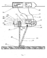
図1は、本発明における水域環境100中の有害物質を非侵襲的に検出するための装置の概略図である。中性子発生器101は、重水素イオン102を三重水素ターゲット103と衝突させ、D+T→a+nという化学反応を起こさせる。当該化学反応からは、重水素のエネルギと比較して遥かに高いエネルギが放出されるので、粒子104及び中性子105が、空間内に略等方的に生成され、略連続的に移動する。中性子の発生から放たれた粒子104は、中性子発生器101の壁に設けられている検出システム106a,106b,106cによって記録される。当該検出システムは、数cmの縦横高さの寸法を有するシリコン検出器又はシンチレーション検出器から成る場合がある。選択された中性子は、空気を吐出することによって、特定の大きさを有する、例えば直径30cm及び最大高さ3mのガイド108の内部において検出対象物体107に向かって移動する。代替的には、ガイドは、空気又は他のガス、例えばヘリウムによって充填されている。これにより、中性子の水中への吸収及び水中における中性子の減速を防止することができる。ガイド108は、厚さ約1mmのステンレス鋼から構成される伸縮式チューブとされ、ガイド108の両端は、非常に薄肉の、例えば厚さ0.5mmのシートによって終端されている。被験物体の内部を移動する高速中性子は、当該党則中性子を励起する被験物体の原子核に吸収されるか、及び/又は非弾性的に散乱されるので、例えば中性子+原子核→励起された原子核+中性子→原子核+中性子+ガンマ量子との化学反応を発生させる。
[Example]
FIG. 1 is a schematic view of an apparatus for noninvasively detecting harmful substances in the
原子核は基底状態に下方遷移しつつ、ガンマ量子109を放射するが、エネルギは原子核それぞれに特有である。原子核によって放射されたガンマ量子の一部は、特定の大きさを有するガイド110の内部においてガンマ量子検出器に向かって移動し、空気が、ガイド110から吐出される。上述の場合には、ガイドが、代替的に空気又は他のガス、例えばヘリウムで充填されている。これにより、ガンマ量子の水中への吸収及び水中におけるガンマ量子の散乱が防止される。ガイド110は、厚さ約1mmのステンレス鋼から成る伸縮式チューブから作られており、ガイド110の両端は、非常に薄肉の、例えば厚さ0.5mmのシートによって終端されている。検出器111は、記録されたガンマ量子109のエネルギを計測する。さらに、検出器111は、検出器111の内部におけるガンマ量子109の衝突位置と、粒子104の検知からガンマ量子検出器111の信号の検知に至るまでの経過時間とを決定する。時間の計測と粒子104及びガンマ量子109の位置とをターゲット103の既知の位置と相互作用させ、中性子ガイド108に対するガンマ量子ガイド110の相対的な距離及び角度を変化させることによって、検出対象物体内の危険性物質の密度分布を決定することができる。図2及び図3は、ガイドを再構成することによって、検出器に到達するガンマ量子が反応する(例えば泥の中の)海底の下方の深さを決定する方法を概略的に表わす。ガイド208及びガイド210の直径とガイド208及びガイド210の長さとの比が十分に小さい(0.14より小さい)場合には、ガンマ量子が反応する深さは、ガンマ量子検出器211による粒子204の検知から信号の検知までの経過時間Δtを計測することによって決定される。以下の数式[数1]が成立する。
The nuclei emit gamma quanta 109 while transitioning down to the ground state, and the energy is unique to each nucleus. A part of the gamma quanta emitted by the nucleus moves toward the gamma quantum detector inside the guide 110 having a specific size, and air is discharged from the guide 110. In the case described above, the guide is alternatively filled with air or another gas, for example helium. This prevents the absorption of gamma quanta into water and the scattering of gamma quanta in water. The guide 110 is made of a telescopic tube made of stainless steel having a thickness of about 1 mm, and both ends of the guide 110 are terminated by a very thin sheet having a thickness of 0.5 mm, for example. The detector 111 measures the energy of the recorded gamma quantum 109. Furthermore, the detector 111 determines the collision position of the gamma quanta 109 inside the detector 111 and the elapsed time from the detection of the particle 104 to the detection of the signal of the gamma quantum detector 111. By interacting the time measurement and the position of the particle 104 and gamma quantum 109 with the known position of the target 103 and changing the relative distance and angle of the gamma quantum guide 110 with respect to the
![]()
![]()
[数1]において、tは、ターゲット203から検出器206cに至るまでの発生したα粒子204の飛翔時間とされ、t′n及びtnはそれぞれ、ガイド208内のターゲットから周知の距離lnに亘る中性子205の飛翔時間、及び、中性子ガイド208の端部から被験物体207内の反応部位212に至る中性子204の飛翔時間とされる。同様に、tγは、ガイド210の既知の一定長さlγに亘るガンマ量子209の飛翔時間とされ、t′γは、被験物体207の内部における中性子205の反応部位212からガイド210の入口213に至るまでのガンマ量子209の飛翔時間を示している。これら飛翔時間は、周知の粒子速度によって、[数2]のように表現可能とされる。
In Equation 1], t is the time of flight of
![]()
![]()
粒子204の速度と中性子205の速度とは一定であって、粒子204及び中性子205の既知のエネルギによって決定され、ガンマ量子209は、光速cで飛翔する。ガイド208の端部214から被験物体207内部の反応部位212に至るまでの中性子205の飛翔距離xと、中性子205の反応部位212からガイド210の入口213に至るまでのガンマ量子209の飛翔距離yは、[数3]のように関連付けられている。
The velocity of the
![]()
![]()
[数3]のように、φは、ガイド208の軸線とガイド210の軸線210とが成す角度とされ、変数である。これにより、[数4]のように、ガイド208の入口214からどのくらいの距離で反応が生じたのかを決定することができる。
As in [Expression 3], φ is an angle formed by the axis of the guide 208 and the

ガイド208,210の長さに対する直径の比が大きい場合には、中性子205が影響を受ける深さxは、このような場所をガイド208,210の両方に共通する領域215において探索することによって、時間Δtの計測値から決定可能とされる。ターゲット203から当該地点に至るまでの中性子205の飛翔時間と、当該場所から検出器211に至るまでのガンマ量子209の飛翔時間との合計が、計測された時間Δtに最も近い。
If the ratio of the diameter to the length of the
ガイド208,210の相対位置を変化させることによって、及び、ガイド208,210が成す角度を変化させることによって、深さに関するさらなる情報を得ることができる。ガイド208とガイド210との間における距離d1及びd2(図2参照)を変化させることによって、被験物体207の異なる部分から放射されたガンマ量子を様々な深さで検知することができる。これにより、被験物体207内部における危険物質の密度分布を決定することができる。
Further information about the depth can be obtained by changing the relative positions of the
中性子ガイド及びガンマ量子ガイドは、幾つかの部品から成る、長さ50cmの伸縮式チューブから作られており、ゴム製ガスケットに接続されている(図4参照)。装置全体を水中に配置させる前に手動で、又は、モジュール118から制御可能とされる機械システムによって、
ガイドの長さを変更することができる。図4は、このような機械システムの一例を表わす。ガイドモジュール302,303,304は、ガイドモジュール302が部品301の内側に配置されているように、且つ、ガイドモジュール304がガイドモジュール303の内側に配置されているように、伸縮自在に接続されている。図5に表わすように、リング状の形態とされるゴム製シール305,306,307は、構成全体を密封している。ガイド300の長さは、サポートレール314,315,316,317に取り付けられている、例えば厚さ10mmのタッピングロッド310,311,312から成るシステムによって調整可能とされる。タッピングロッド310を回転させることによって、他の要素311が駆動され、これによりタッピングロッド312が移動される。ガイド300の長さ調整をするためのシステムは、例えば図3bに表わすように配置されたロッド318,319,320,321から成る、4つのセットから構成されている。当該セットそれぞれが、モータ309によって駆動される。ガイド300とエンジンとが、システム全体を密閉し且つ水から保護するために、フランジ301を介して接続されている。制御システム308によって、装置200の下面322に対するガイド300の角度を変化させることができる。ガイド300の部分それぞれが、良好な中性子反射能力を有している、例えばグラファイトのような薄肉層(約1mm)の材料によって裏当てされている。
The neutron guide and gamma quantum guide are made of a 50 cm long telescoping tube consisting of several parts and connected to a rubber gasket (see FIG. 4). Either manually before placing the entire device in water, or by a mechanical system that can be controlled from the module 118
The length of the guide can be changed. FIG. 4 represents an example of such a mechanical system. The
図6に表わすように、装置200の密封性を維持するために、中性子ガイド208とガンマ量子ガイド210との相対位置を変更することができる。また、ガンマ量子ガイド210の位置のみを変更することができる。ガイド400は、フランジ401に接続されており、フランジ401は、装置200の底部402に密封状態で接続されている。装置200の底部402は、容易に伸縮可能とされる材料から作られているので、ガイド400をガンマ量子検出器403と共に移動させることができる。当該伸縮可能とされる材料は、薄肉且つ波状のシート材料、波状のプラスチック層、又は波状の革とされる。ガイド400は、モータ404、角度405を変化させるためのシステム、及びガンマ量子検出器403と共に、例えばガイド400及び検出器403の位置変化をもたらす直線的な横移動に基づいて、駆動システム406に接続されている。
As shown in FIG. 6, the relative position of the neutron guide 208 and the
図1に表わすガンマ量子検出器111は、従来技術に基づく、例えばシンチレーション水晶や半導体を利用することによってガンマ量子を検出するための解決手段に基づいて構成されている。装置100の内側において、検出器の位置が変更可能とされる。粒子検出器106a,106b,106cからの信号とガンマ量子検出器111からの信号とが、信号線112,113を介して、データ取得するための信号サンプリングモジュール114に伝送される。放射された中性子であって、被験物体107には向かわない中性子の反応から得られた背景放射線を除去するために、粒子検出器106a,106bからの信号と同時に記録されたガンマ量子検出器111からのすべての信号が破棄される一方、検出器106cからの信号と同時に記録された信号は検出対象物体からのガンマ量子として扱われる。次に、信号サンプリングモジュール114は、ケーブル又は無線信号を利用して、容器117に配置されている処理モジュール120にデータを送信するので、装置100は、制御モジュール118によって当該データに基づいて制御される。信号サンプリングモジュール114からの信号は、通信回線119又は電波を介して、モジュール101,106,111,114を制御する受信モジュール120と装置100を移動させるためのモータ121とに送信される。
The gamma quantum detector 111 shown in FIG. 1 is configured based on a solution based on the prior art, for example, for detecting gamma quanta by using a scintillation crystal or a semiconductor. Inside the
モジュール117によって、物質107が識別される。当該識別は、12C原子核(エネルギ4.43MeV)、16O原子核(6.13MeVエネルギ)、14N原子核(エネルギ2.31MeV及び5.11MeV)、及び検体を構成する他の元素、例えば19F原子核(エネルギ1.5MeV及び3.9MeV)、32S原子核(3.8MeVエネルギ)や35Cl(3.0MeVエネルギ)から放射された、複数の検知された特徴的なガンマ量子に基づいて行われる。中性子と様々な原子核との反応の様々な可能性、及び様々なエネルギを有するガンマ量子の検出効率を考慮して、被検物体を構築する元素それぞれの原子の数が再構成された後に、モジュール117のデータベースに格納された危険物質の既知の化学量と比較される。
Module 117 identifies the
100 装置
101 中性子発生器
102 重水素イオン
103 三重水素イオン
104 素粒子
105 中性子
106a 検出システム
106b 検出システム
106c 検出システム
107 検出対象物体(被験物体)
108 ガイド
109 ガンマ量子
110 ガイド
111 ガンマ量子検出器
114 信号サンプリングモジュール
117 容器
118 モジュール
120 処理モジュール
121 モータ
200 装置
203 ターゲット
204 粒子
206a 検出器
206b 検出器
206c 検出器
207 被験物体
208 中性子ガイド
209 ガンマ量子
210 ガンマ量子ガイド
212 反応部位
213 (ガイド210の)入口
214 (ガイド208の)端部
302 ガイドモジュール
303 ガイドモジュール
304 ガイドモジュール
305 シール
306 シール
307 シール
308 制御システム
309 モータ
310 タッピングロッド
311 タッピングロッド
312 タッピングロッド
315 サポートレール
316 サポートレール
317 サポートレール
322 下面
400 ガイド
401 フランジ
402 (装置200の)底部
403 ガンマ量子検出器
404 モータ
405 角度
406 駆動システム
DESCRIPTION OF
108 guide 109 gamma quantum 110 guide 111 gamma quantum detector 114 signal sampling module 117 container 118 module 120 processing module 121
Claims (11)
前記装置が、前記高速中性子発生器(101)と接続されている中性子ガイド(108)及び/又は前記ガンマ量子検出器(111)と接続されているガンマ量子ガイド(110)を備えており、前記中性子ガイド及び/又はガンマ量子ガイド(108,110)は前記ハウジングの外部で前記ハウジングに設けられており、前記高速中性子発生器(101)に結合された前記中性子ガイド(108)と前記ガンマ量子検出器(111)に接続された前記ガンマ量子ガイド(110)との間の距離は変更可能であり、前記中性子ガイド(108)及び/又はガンマ量子ガイド(110)は伸縮可能であることを特徴とする装置。 An apparatus for non-invasive detection of harmful substances in an aquatic environment, the apparatus comprising a fast neutron generator (101) and a gamma quantum detector (111) surrounded by an alpha particle detector (106) ), The fast neutron generator (101) emits neutrons toward the test object (107), and the gamma quantum detector (111) In the apparatus for detecting gamma quanta emitted by nuclei of the test object (107),
The apparatus comprises a neutron guide (108) connected to the fast neutron generator (101) and / or a gamma quantum guide (110) connected to the gamma quantum detector (111), A neutron guide and / or a gamma quantum guide (108, 110) is provided in the housing outside the housing, and the neutron guide (108) coupled to the fast neutron generator (101) and the gamma quantum detection. The distance between the gamma quantum guide (110) connected to the vessel (111) can be changed, and the neutron guide (108) and / or the gamma quantum guide (110) can be expanded and contracted. Device to do.
a)中性子発生器(101)を利用することによって、5MeV〜20MeVの範囲にあるエネルギで高速中性子を発生させるステップと、
b)前記ステップa)において発生された前記高速中性子を検出対象物体(107)に向かって視準するステップと、
c)被験物体の原子核を励起状態から基底状態に遷移させる際に放射されるガンマ量子を検出するステップと、
を備えている前記方法において、
発生された前記高速中性子が中性子ガイド(108)の内部において移送され、かつ/又は放射された前記ガンマ量子がガンマ量子ガイド(110)の内部において移送され、
前記中性子ガイド及び/又はガンマ量子ガイド(108,110)は、前記中性子発生器(101)を収容するハウジングの外部で、前記ハウジングに設けられており、
前記中性子発生器(101)に結合された前記中性子ガイド(108)と前記ガンマ量子ガイド(110)との間の距離は変更可能であり、
前記中性子ガイド(108)及び/又はガンマ量子ガイド(110)は伸縮可能であることを特徴とする方法。 A method for non-invasively detecting harmful substances in an aquatic environment,
a) generating fast neutrons with an energy in the range of 5 MeV to 20 MeV by utilizing a neutron generator (101);
b) collimating the fast neutrons generated in step a) toward the object to be detected (107);
c) detecting gamma quanta emitted when transitioning the nucleus of the test object from the excited state to the ground state;
In the method comprising:
The generated fast neutrons are transported inside the neutron guide (108) and / or the emitted gamma quanta are transported inside the gamma quantum guide (110);
The neutron guide and / or gamma quantum guide (108, 110) is provided in the housing outside the housing that houses the neutron generator (101),
The distance between the neutron guide (108) coupled to the neutron generator (101) and the gamma quantum guide (110) can be varied;
Wherein said neutron guide (108) and / or gamma quanta guide (110) is telescopic.
Applications Claiming Priority (3)
| Application Number | Priority Date | Filing Date | Title |
|---|---|---|---|
| PLP.409388 | 2014-09-07 | ||
| PL409388A PL225474B1 (en) | 2014-09-07 | 2014-09-07 | Device and method for non-invasive detection of dangerous materials in water environment |
| PCT/PL2015/050021 WO2016036264A1 (en) | 2014-09-07 | 2015-06-08 | Device and method for non-invasive detection of hazardous materials in the aquatic environment |
Publications (2)
| Publication Number | Publication Date |
|---|---|
| JP2017526928A JP2017526928A (en) | 2017-09-14 |
| JP6580675B2 true JP6580675B2 (en) | 2019-09-25 |
Family
ID=53610960
Family Applications (1)
| Application Number | Title | Priority Date | Filing Date |
|---|---|---|---|
| JP2017513058A Active JP6580675B2 (en) | 2014-09-07 | 2015-06-08 | Apparatus and method for non-invasive detection of toxic substances in aquatic environment |
Country Status (5)
| Country | Link |
|---|---|
| US (1) | US10126257B2 (en) |
| EP (1) | EP3189356B1 (en) |
| JP (1) | JP6580675B2 (en) |
| PL (1) | PL225474B1 (en) |
| WO (1) | WO2016036264A1 (en) |
Families Citing this family (4)
| Publication number | Priority date | Publication date | Assignee | Title |
|---|---|---|---|---|
| CH713761A2 (en) * | 2017-05-08 | 2018-11-15 | Mircea Tudor Scan Tech Sa | System and method for non-intrusive inspection of boats. |
| JP7311161B2 (en) * | 2018-04-12 | 2023-07-19 | 国立研究開発法人理化学研究所 | Nondestructive inspection method and apparatus |
| JP7223992B2 (en) * | 2019-02-27 | 2023-02-17 | 株式会社トプコン | Nondestructive inspection system and nondestructive inspection method |
| RU195097U1 (en) * | 2019-08-23 | 2020-01-15 | Федеральное Государственное Унитарное Предприятие "Всероссийский Научно-Исследовательский Институт Автоматики Им.Н.Л.Духова" (Фгуп "Внииа") | Device for detecting explosive, poisonous and fissile materials on the seabed |
Family Cites Families (20)
| Publication number | Priority date | Publication date | Assignee | Title |
|---|---|---|---|---|
| JPS6418107A (en) * | 1987-07-13 | 1989-01-20 | Kaneo Hirabayashi | Underwater optical waveguide |
| US5326970A (en) * | 1991-11-12 | 1994-07-05 | Bayless John R | Method and apparatus for logging media of a borehole |
| JP2002507746A (en) * | 1998-02-18 | 2002-03-12 | ハイエナジー マイクロデバイセス インコーポレイテッド | Method and apparatus for detecting, locating and analyzing compounds using activation method by subatomic particles |
| US20030165213A1 (en) | 1998-02-18 | 2003-09-04 | Maglich Bogdan C. | Method and apparatus for neutron microscopy with stoichiometric imaging |
| US20030165212A1 (en) | 1998-02-18 | 2003-09-04 | Maglich Bogdan C. | Method and apparatus for detecting, locating, and analyzing chemical compounds using subatomic particle activation |
| US6603122B2 (en) * | 2001-05-24 | 2003-08-05 | Ut-Battelle, Llc | Probe for contamination detection in recyclable materials |
| JP2004028824A (en) * | 2002-06-26 | 2004-01-29 | Hitachi Ltd | Crustal movement monitoring device and crustal movement monitoring system |
| JP2004108912A (en) * | 2002-09-18 | 2004-04-08 | Hitachi Ltd | Detection device and detection method using neutrons |
| US7864913B2 (en) * | 2004-02-19 | 2011-01-04 | Kabushiki Kaisha Toshiba | Fast reactor having reflector control system and neutron reflector thereof |
| US7359480B2 (en) * | 2004-04-23 | 2008-04-15 | Lawrence Livermore National Security, Llc | Neutron interrogation system using high gamma ray signature to detect contraband special nuclear materials in cargo |
| JP4587769B2 (en) * | 2004-10-20 | 2010-11-24 | 日立Geニュークリア・エナジー株式会社 | Radiation damage measuring device |
| US7209540B2 (en) * | 2004-12-22 | 2007-04-24 | Eg&G Middle East | Vessel scanning system |
| US7420175B2 (en) * | 2005-04-13 | 2008-09-02 | University Of Houston | Explosives detection by directional fast neutron beams scan with associated particles |
| US8767905B2 (en) * | 2008-03-07 | 2014-07-01 | Babcock & Wilcox Technical Services Group, Inc. | Combinatorial heterogeneous-homogeneous reactor |
| US8338777B2 (en) * | 2009-09-09 | 2012-12-25 | Bake Hughes Incorporated | Apparatus and method for well logging utilizing associate particle imaging |
| DE102010056517A1 (en) * | 2010-12-29 | 2012-07-05 | Atlas Elektronik Gmbh | Recognition device and recognition method for detecting an underwater body arranged in a body of water and having a chemical substance, and system with underwater vehicle and recognition device |
| US8921801B2 (en) * | 2011-01-07 | 2014-12-30 | Brookhaven Science Associates, Llc | Detection system for high-resolution gamma radiation spectroscopy with neutron time-of-flight filtering |
| MX345317B (en) * | 2012-06-01 | 2017-01-23 | Rapiscan Systems Inc | Methods and systems for time-of-flight neutron interrogation for material descrimination. |
| US9392681B2 (en) * | 2012-08-03 | 2016-07-12 | Schlumberger Technology Corporation | Borehole power amplifier |
| US9268043B2 (en) * | 2012-09-27 | 2016-02-23 | Alexander DeVolpi | Radiation-monitoring system with correlated hodoscopes |
-
2014
- 2014-09-07 PL PL409388A patent/PL225474B1/en unknown
-
2015
- 2015-06-08 WO PCT/PL2015/050021 patent/WO2016036264A1/en active Application Filing
- 2015-06-08 JP JP2017513058A patent/JP6580675B2/en active Active
- 2015-06-08 US US15/509,013 patent/US10126257B2/en not_active Expired - Fee Related
- 2015-06-08 EP EP15738491.8A patent/EP3189356B1/en active Active
Also Published As
| Publication number | Publication date |
|---|---|
| PL225474B1 (en) | 2017-04-28 |
| PL409388A1 (en) | 2016-03-14 |
| JP2017526928A (en) | 2017-09-14 |
| WO2016036264A1 (en) | 2016-03-10 |
| US20170254763A1 (en) | 2017-09-07 |
| EP3189356B1 (en) | 2019-10-30 |
| US10126257B2 (en) | 2018-11-13 |
| EP3189356A1 (en) | 2017-07-12 |
Similar Documents
| Publication | Publication Date | Title |
|---|---|---|
| RU2206080C1 (en) | Method for detecting explosive substance availability in an article under examination | |
| JP6580675B2 (en) | Apparatus and method for non-invasive detection of toxic substances in aquatic environment | |
| Avrorin et al. | Search for high-energy neutrinos from GW170817 with the Baikal-GVD neutrino telescope | |
| US20100072367A1 (en) | Procedure for the detection of ionizing radiation | |
| KR102130125B1 (en) | Marine gamma-ray isotopes analyzer using scintillation detector and autonomous underwater vehicles and marine gamma-ray isotopes analysis method thereby | |
| CN203881957U (en) | Detector based on neutrino and used for detecting nuclear submarine | |
| Sibczyński et al. | Monte Carlo N-Particle simulations of an underwater chemical threats detection system using neutron activation analysis | |
| Valkovic et al. | An underwater system for explosive detection | |
| Sudac et al. | The underwater detection of TNT explosive | |
| RU2185614C1 (en) | Detector of hidden explosives | |
| CA2951424A1 (en) | Underwater gamma and neutron detection | |
| Valkovic | New/future approaches to explosive/chemicals detection | |
| KR102203984B1 (en) | A mine detector with neutron source and methodology for detecting mine using it | |
| Silarski | Hazardous substance detection in water environments using neutron beams: the SABAT project | |
| RU123957U1 (en) | DEVICE FOR DETECTION AND IDENTIFICATION OF HIDDEN HAZARDOUS SUBSTANCES UNDER WATER (OPTIONS) | |
| Silarski et al. | Project of the underwater system for chemical threat detection | |
| CN211123311U (en) | Detection device for underwater suspected explosion source | |
| WO2006075934A2 (en) | Device for detecting an explosive in objects under investigation | |
| Silarski et al. | Underwater detection of dangerous substances: status the SABAT project | |
| CN207148004U (en) | Seabed integrated neutron activation analysis system in situ | |
| Schwartz et al. | An overview of underwater technologies for operations involving underwater munitions | |
| US4259577A (en) | Method and means for predicting contents of containers | |
| GB2426325A (en) | Beta radiation detector | |
| RU123956U1 (en) | DEVICE FOR DETECTION AND IDENTIFICATION OF HIDDEN HAZARDOUS SUBSTANCES UNDER WATER | |
| RU2503955C1 (en) | Device to detect and identify hidden hazardous substances under water |
Legal Events
| Date | Code | Title | Description |
|---|---|---|---|
| A621 | Written request for application examination |
Free format text: JAPANESE INTERMEDIATE CODE: A621 Effective date: 20180111 |
|
| A977 | Report on retrieval |
Free format text: JAPANESE INTERMEDIATE CODE: A971007 Effective date: 20181012 |
|
| A131 | Notification of reasons for refusal |
Free format text: JAPANESE INTERMEDIATE CODE: A131 Effective date: 20181022 |
|
| A521 | Request for written amendment filed |
Free format text: JAPANESE INTERMEDIATE CODE: A523 Effective date: 20181206 |
|
| A131 | Notification of reasons for refusal |
Free format text: JAPANESE INTERMEDIATE CODE: A131 Effective date: 20190520 |
|
| A521 | Request for written amendment filed |
Free format text: JAPANESE INTERMEDIATE CODE: A523 Effective date: 20190717 |
|
| TRDD | Decision of grant or rejection written | ||
| A01 | Written decision to grant a patent or to grant a registration (utility model) |
Free format text: JAPANESE INTERMEDIATE CODE: A01 Effective date: 20190805 |
|
| A61 | First payment of annual fees (during grant procedure) |
Free format text: JAPANESE INTERMEDIATE CODE: A61 Effective date: 20190828 |
|
| R150 | Certificate of patent or registration of utility model |
Ref document number: 6580675 Country of ref document: JP Free format text: JAPANESE INTERMEDIATE CODE: R150 |
|
| R250 | Receipt of annual fees |
Free format text: JAPANESE INTERMEDIATE CODE: R250 |
|
| R250 | Receipt of annual fees |
Free format text: JAPANESE INTERMEDIATE CODE: R250 |
|
| R250 | Receipt of annual fees |
Free format text: JAPANESE INTERMEDIATE CODE: R250 |