JP6580556B2 - Method for inspecting abnormalities by image analysis - Google Patents
Method for inspecting abnormalities by image analysis Download PDFInfo
- Publication number
- JP6580556B2 JP6580556B2 JP2016509523A JP2016509523A JP6580556B2 JP 6580556 B2 JP6580556 B2 JP 6580556B2 JP 2016509523 A JP2016509523 A JP 2016509523A JP 2016509523 A JP2016509523 A JP 2016509523A JP 6580556 B2 JP6580556 B2 JP 6580556B2
- Authority
- JP
- Japan
- Prior art keywords
- mandrel
- preform
- fiber preform
- weaving
- image
- Prior art date
- Legal status (The legal status is an assumption and is not a legal conclusion. Google has not performed a legal analysis and makes no representation as to the accuracy of the status listed.)
- Active
Links
Images


Classifications
-
- G—PHYSICS
- G01—MEASURING; TESTING
- G01N—INVESTIGATING OR ANALYSING MATERIALS BY DETERMINING THEIR CHEMICAL OR PHYSICAL PROPERTIES
- G01N21/00—Investigating or analysing materials by the use of optical means, i.e. using sub-millimetre waves, infrared, visible or ultraviolet light
- G01N21/84—Systems specially adapted for particular applications
- G01N21/88—Investigating the presence of flaws or contamination
- G01N21/89—Investigating the presence of flaws or contamination in moving material, e.g. running paper or textiles
- G01N21/892—Investigating the presence of flaws or contamination in moving material, e.g. running paper or textiles characterised by the flaw, defect or object feature examined
- G01N21/898—Irregularities in textured or patterned surfaces, e.g. textiles, wood
-
- B—PERFORMING OPERATIONS; TRANSPORTING
- B29—WORKING OF PLASTICS; WORKING OF SUBSTANCES IN A PLASTIC STATE IN GENERAL
- B29C—SHAPING OR JOINING OF PLASTICS; SHAPING OF MATERIAL IN A PLASTIC STATE, NOT OTHERWISE PROVIDED FOR; AFTER-TREATMENT OF THE SHAPED PRODUCTS, e.g. REPAIRING
- B29C53/00—Shaping by bending, folding, twisting, straightening or flattening; Apparatus therefor
- B29C53/56—Winding and joining, e.g. winding spirally
- B29C53/58—Winding and joining, e.g. winding spirally helically
-
- B—PERFORMING OPERATIONS; TRANSPORTING
- B65—CONVEYING; PACKING; STORING; HANDLING THIN OR FILAMENTARY MATERIAL
- B65H—HANDLING THIN OR FILAMENTARY MATERIAL, e.g. SHEETS, WEBS, CABLES
- B65H26/00—Warning or safety devices, e.g. automatic fault detectors, stop-motions, for web-advancing mechanisms
- B65H26/02—Warning or safety devices, e.g. automatic fault detectors, stop-motions, for web-advancing mechanisms responsive to presence of irregularities in running webs
-
- B—PERFORMING OPERATIONS; TRANSPORTING
- B65—CONVEYING; PACKING; STORING; HANDLING THIN OR FILAMENTARY MATERIAL
- B65H—HANDLING THIN OR FILAMENTARY MATERIAL, e.g. SHEETS, WEBS, CABLES
- B65H63/00—Warning or safety devices, e.g. automatic fault detectors, stop-motions ; Quality control of the package
- B65H63/06—Warning or safety devices, e.g. automatic fault detectors, stop-motions ; Quality control of the package responsive to presence of irregularities in running material, e.g. for severing the material at irregularities ; Control of the correct working of the yarn cleaner
- B65H63/062—Electronic slub detector
- B65H63/065—Electronic slub detector using photo-electric sensing means, i.e. the defect signal is a variation of light energy
-
- D—TEXTILES; PAPER
- D03—WEAVING
- D03D—WOVEN FABRICS; METHODS OF WEAVING; LOOMS
- D03D51/00—Driving, starting, or stopping arrangements; Automatic stop motions
- D03D51/06—Driving, starting, or stopping arrangements; Automatic stop motions using particular methods of stopping
- D03D51/08—Driving, starting, or stopping arrangements; Automatic stop motions using particular methods of stopping stopping at definite point in weaving cycle, or moving to such point after stopping
-
- D—TEXTILES; PAPER
- D03—WEAVING
- D03J—AUXILIARY WEAVING APPARATUS; WEAVERS' TOOLS; SHUTTLES
- D03J1/00—Auxiliary apparatus combined with or associated with looms
- D03J1/004—Detection and repair of broken warp yarns
-
- D—TEXTILES; PAPER
- D03—WEAVING
- D03J—AUXILIARY WEAVING APPARATUS; WEAVERS' TOOLS; SHUTTLES
- D03J1/00—Auxiliary apparatus combined with or associated with looms
- D03J1/007—Fabric inspection on the loom and associated loom control
-
- D—TEXTILES; PAPER
- D06—TREATMENT OF TEXTILES OR THE LIKE; LAUNDERING; FLEXIBLE MATERIALS NOT OTHERWISE PROVIDED FOR
- D06H—MARKING, INSPECTING, SEAMING OR SEVERING TEXTILE MATERIALS
- D06H3/00—Inspecting textile materials
- D06H3/08—Inspecting textile materials by photo-electric or television means
-
- D—TEXTILES; PAPER
- D06—TREATMENT OF TEXTILES OR THE LIKE; LAUNDERING; FLEXIBLE MATERIALS NOT OTHERWISE PROVIDED FOR
- D06H—MARKING, INSPECTING, SEAMING OR SEVERING TEXTILE MATERIALS
- D06H3/00—Inspecting textile materials
- D06H3/12—Detecting or automatically correcting errors in the position of weft threads in woven fabrics
-
- G—PHYSICS
- G01—MEASURING; TESTING
- G01N—INVESTIGATING OR ANALYSING MATERIALS BY DETERMINING THEIR CHEMICAL OR PHYSICAL PROPERTIES
- G01N21/00—Investigating or analysing materials by the use of optical means, i.e. using sub-millimetre waves, infrared, visible or ultraviolet light
- G01N21/84—Systems specially adapted for particular applications
- G01N21/88—Investigating the presence of flaws or contamination
- G01N21/89—Investigating the presence of flaws or contamination in moving material, e.g. running paper or textiles
- G01N21/8901—Optical details; Scanning details
- G01N21/8903—Optical details; Scanning details using a multiple detector array
-
- B—PERFORMING OPERATIONS; TRANSPORTING
- B29—WORKING OF PLASTICS; WORKING OF SUBSTANCES IN A PLASTIC STATE IN GENERAL
- B29C—SHAPING OR JOINING OF PLASTICS; SHAPING OF MATERIAL IN A PLASTIC STATE, NOT OTHERWISE PROVIDED FOR; AFTER-TREATMENT OF THE SHAPED PRODUCTS, e.g. REPAIRING
- B29C70/00—Shaping composites, i.e. plastics material comprising reinforcements, fillers or preformed parts, e.g. inserts
- B29C70/04—Shaping composites, i.e. plastics material comprising reinforcements, fillers or preformed parts, e.g. inserts comprising reinforcements only, e.g. self-reinforcing plastics
- B29C70/28—Shaping operations therefor
- B29C70/30—Shaping by lay-up, i.e. applying fibres, tape or broadsheet on a mould, former or core; Shaping by spray-up, i.e. spraying of fibres on a mould, former or core
- B29C70/32—Shaping by lay-up, i.e. applying fibres, tape or broadsheet on a mould, former or core; Shaping by spray-up, i.e. spraying of fibres on a mould, former or core on a rotating mould, former or core
-
- F—MECHANICAL ENGINEERING; LIGHTING; HEATING; WEAPONS; BLASTING
- F01—MACHINES OR ENGINES IN GENERAL; ENGINE PLANTS IN GENERAL; STEAM ENGINES
- F01D—NON-POSITIVE DISPLACEMENT MACHINES OR ENGINES, e.g. STEAM TURBINES
- F01D21/00—Shutting-down of machines or engines, e.g. in emergency; Regulating, controlling, or safety means not otherwise provided for
- F01D21/04—Shutting-down of machines or engines, e.g. in emergency; Regulating, controlling, or safety means not otherwise provided for responsive to undesired position of rotor relative to stator or to breaking-off of a part of the rotor, e.g. indicating such position
- F01D21/045—Shutting-down of machines or engines, e.g. in emergency; Regulating, controlling, or safety means not otherwise provided for responsive to undesired position of rotor relative to stator or to breaking-off of a part of the rotor, e.g. indicating such position special arrangements in stators or in rotors dealing with breaking-off of part of rotor
-
- G—PHYSICS
- G01—MEASURING; TESTING
- G01N—INVESTIGATING OR ANALYSING MATERIALS BY DETERMINING THEIR CHEMICAL OR PHYSICAL PROPERTIES
- G01N21/00—Investigating or analysing materials by the use of optical means, i.e. using sub-millimetre waves, infrared, visible or ultraviolet light
- G01N21/84—Systems specially adapted for particular applications
- G01N2021/8472—Investigation of composite materials
Description
本発明は、一般的に複合材料からガスタービンのケースを製造する分野に関し、特に、航空機エンジンのガスタービンに用いられるファン保持用ケースに関する。 The present invention relates generally to the field of manufacturing gas turbine cases from composite materials, and more particularly to fan holding cases used in aircraft engine gas turbines.
ファン保持用ケースの一般的な方法では、比較的に薄い壁を用いて構成して、エンジンの内部に空気を送気可能にする通路を定めて、ファンブレードの先端部経路に合わせて摩耗性材料を支持させているが、さらに場合によっては音響処理用の被覆を支持させて、かつファン上方の壁の外側に取り付けられた外枠構造を支持させているが、これは、破片、たとえば、吸い込まれた物体や、遠心分離によって突出して損傷したブレードの断片を保持させて、これらがケースを通過して、航空機の他の部位に到達することを防ぐためである。 A common method for holding a fan is to use a relatively thin wall to define a passage that allows air to flow inside the engine, and to wear along the tip of the fan blade. Although supporting the material, and possibly supporting the acoustic treatment coating and supporting the outer frame structure attached to the outside of the wall above the fan, This is to keep inhaled objects and fragments of blades that are damaged due to centrifugation and prevent them from passing through the case and reaching other parts of the aircraft.
複合材料を用いてファン保持用ケースを製造するための提案は既に存在している。一例を挙げると、欧州特許第1961923号の文献を参照できるが、これには、様々な厚さの複合材料を用いてケースを製造することが開示されており、この方法は、繊維組織を重ね合わせた層として繊維強化材を形成することと、母材とともに繊維強化材を高密度化することを含んでいる。より具体的には、この文献は、繊維組織を三次元製織するために巻き取りマンドレルを用いており、この組織は次に、製造されるケースの輪郭に相当する輪郭を有する含浸マンドレル上に重ね合わせた層として、巻かれている。このようにして得られたプリフォームは、含浸マンドレル上に保持されて、樹脂とともに含浸処理されるが、その樹脂は次に重合化される。 Proposals already exist for manufacturing fan holding cases using composite materials. As an example, reference can be made to the document of European Patent No. 1961923, which discloses the production of cases using composite materials of various thicknesses, and this method involves the overlaying of fiber structures. Forming the fiber reinforcement as a combined layer and densifying the fiber reinforcement together with the base material. More specifically, this document uses a winding mandrel to three-dimensionally weave the fibrous structure, which is then overlaid on an impregnated mandrel having a contour corresponding to the contour of the case to be produced. It is rolled up as a combined layer. The preform thus obtained is held on an impregnation mandrel and impregnated with a resin, which is then polymerized.
しかしながら、巻き上げ作業中に、巻き上げ機の上に通常配置されている作業プラットホーム上に位置している作業者には、プリフォームの一部(より具体的には、底面)を視認することができないという事態が生じていた。この構成のため、プリフォームに影響を及ぼし得る様々な異常性、たとえば、汚染(粘着テープ、切断されたファイバーなど)の検出が防がれたり、プリフォームの一部での織り不良が作業者によって視覚によって検査することができなかった。不幸なことに、この巻き上げ作業は、そのような異常性が依然として検出され得る製造工程の最後のステップであった。したがって、それらが巻き上げ中に識別されない場合には、それらはプリフォームの重ね合わせられた層の中に覆われるため、隠されることになる。 However, a part of the preform (more specifically, the bottom surface) cannot be visually recognized by the worker who is located on the work platform that is normally disposed on the winder during the winding work. That happened. This configuration prevents the detection of various anomalies that can affect the preform, such as contamination (adhesive tape, cut fibers, etc.), and poor weaving on parts of the preform. Could not be visually inspected. Unfortunately, this winding up was the last step in the manufacturing process where such anomalies could still be detected. Thus, if they are not identified during winding, they will be hidden because they are covered in the overlaid layer of the preform.
巻き上げ作業中に、プリフォームの隠された表面上に位置するこれら異常性を観察することが重要であるが、従前の織り作業の最中にこれら異常性を検出することができなかった。何故ならば、たとえば、織機上で織る際と同様にそれら異常性が隠されるためである。 While it is important to observe these anomalies located on the hidden surface of the preform during the winding operation, these anomalies could not be detected during previous weaving operations. This is because, for example, these abnormalities are hidden in the same way as when weaving on a loom.
この結果、巻き上げの前に、プリフォームの隠された表面上の汚染と織り不良の双方を検出可能にした、巻き上げ機または織機(編み機)に対する需要が存在する。巻き上げの後、上述のようなプリフォームの不純物や不良を検査することが不可能になるため、巻き上げ作業を検証することは不可能となる。 As a result, there is a need for a hoist or loom (knitting machine) that makes it possible to detect both contamination and poor weaving on the hidden surface of the preform prior to winding. After the winding, it becomes impossible to inspect impurities and defects of the preform as described above, so that it is impossible to verify the winding operation.
本発明の主要な課題は、含浸段階の前に、プリフォームを修復するか、またははねるようにした解決策を提供することにより、上記の需要を和らげることである。本発明の他の課題は、織りおよび/または巻き上げの作業の質を監視するために、異常性の位置、発生、および種類に関するデータを統計的に解析可能にすることである。 The main problem of the present invention is to alleviate the above demand by providing a solution in which the preform is repaired or splashed before the impregnation step. Another object of the present invention is to enable statistical analysis of data regarding the location, occurrence and type of anomalies in order to monitor the quality of weaving and / or winding work.
上記課題は、マンドレル上で繊維プリフォームを織るまたは巻き上げるための機械内で織りの異常性を決定する方法によって達成されるが、このマンドレルは、プリフォームを受け取るために実質的に水平方向に回転軸を有し、かつ制御ユニットによって作動されるモーターによって、回転軸を中心にこのマンドレルは駆動される。この方法では、繊維組織の下側を観察する複数のカメラによって、繊維プリフォームの隠された表面をスキャンして、隠された表面の画像を取得し、さらに画像解析モジュールによって、複数の隣接するスキャン窓内で繊維プリフォームの隠された表面の画像を処理して、そこから織りパターンを抽出して、それらをモジュール内に前もって記憶させていた参照用織りパターンと比較して、この比較の結果、少なくとも1つのスキャン窓中において、2つの織りパターンの間の外観の差が、繊維プリフォーム内の汚染および/または織り不良の結果である異常性の存在を特徴付けることを明らかにした場合、制御ユニットはマンドレルの回転を停止し、異常性が認識されたとき、繊維プリフォーム上のその位置と、予め定められた異常性の種類の中から作業者によって選択されたラベルとが、前記異常性の画像とともに記憶され、認識された異常性が修復されたとき、予め定められた修復の種類の中から作業者によって選択された対応するラベルが前記修復の画像とともに記憶され、認識された異常性と修復された異常性を、前記制御ユニットから作業者に対しアクセス可能な、前記繊維プリフォームの展開された表現または三次元状の表現の中に表示する。 The above task is accomplished by a method for determining weaving anomalies in a machine for weaving or winding a fiber preform on a mandrel, which mandrel rotates substantially horizontally to receive the preform. The mandrel is driven about the axis of rotation by a motor having an axis and operated by a control unit. In this method, the hidden surface of the fiber preform is scanned by a plurality of cameras observing the underside of the fiber tissue to obtain an image of the hidden surface, and further, a plurality of adjacent images are obtained by the image analysis module. Process the hidden surface image of the fiber preform in the scan window and extract the weave pattern from it and compare it to the reference weave pattern previously stored in the module. As a result, when it is revealed that in at least one scan window, the difference in appearance between the two weave patterns characterizes the presence of anomalies that are the result of contamination and / or poor weaving in the fiber preform, The control unit stops the mandrel from rotating, and when an anomaly is recognized, its position on the fiber preform and the predetermined anomaly species The label selected by the operator from among the images is stored together with the image of the anomaly, and when the recognized anomaly is repaired, the response selected by the operator from a predetermined type of repair An unfolded representation of the fiber preform or a three-dimensional shape, wherein a label to be stored is stored with the image of the repair and the recognized and repaired anomalies are accessible to the operator from the control unit Display in the expression.
複数のスキャン窓内で繊維プリフォームの画像を実時間またはリアルタイムで解析することにより、織りパターン中の汚染や不良を監視して、行われた織り作業または巻き上げ作業を修正したり、または、必要に応じて、それらを無効化することを可能にする。この結果、航空機エンジン用に複合材料からファン保持用ケースを製造するのによく適合する機械が得られる。特に、この機械の工程は完全に自動化できるため、そのようなケース用の製造サイクル時間を低減するのに貢献する。 Real-time or real-time analysis of fiber preform images in multiple scan windows to monitor contamination and defects in the weaving pattern and to correct or require any weaving or winding operations performed Depending on the, you can disable them. This results in a machine that is well suited for manufacturing fan holding cases from composite materials for aircraft engines. In particular, the process of this machine can be fully automated, which contributes to reducing the manufacturing cycle time for such cases.
好適には、スキャン窓の大きさ、位置、および数は、カメラから得られる画像上で作業者によって直接的に設定される。 Preferably, the size, position and number of scan windows are set directly by the operator on the image obtained from the camera.
有利には、スキャン窓の数は、多くて、繊維プリフォームに向けられるカメラの数に相当する。 Advantageously, the number of scan windows is at most equivalent to the number of cameras directed at the fiber preform.
好適には、前記マンドレルの輪郭と合うように適合されたライトボックス内に複数のカメラを取り付けて、前記繊維プリフォームに出来る限り近づくように配置し、ライトボックスは、446ナノメーター(nm)から500nmの範囲内の波長で青色の光を送り、または620nmから800nmの範囲内の波長で赤色の光を送る。 Preferably, a plurality of cameras are mounted in a light box adapted to match the contour of the mandrel and positioned as close as possible to the fiber preform, and the light box is from 446 nanometers (nm) Blue light is sent at a wavelength in the range of 500 nm, or red light is sent at a wavelength in the range of 620 nm to 800 nm.
有利には、前記外観の差は、カメラからの画像用のグレイレベル曲線の検査の結果である。 Advantageously, the difference in appearance is a result of examination of a gray level curve for an image from the camera.
想定される実施では、前記検査は、少なくとも1つの検出ラインに沿って、または所定の検出領域上で、各スキャン窓内で行われる。 In envisaged implementations, the inspection is performed in each scan window along at least one detection line or on a predetermined detection area.
本発明は、前記マンドレルが巻き取りマンドレルである織機と、前記マンドレルが含浸マンドレルである巻き上げ機の双方に適用可能である。 The present invention is applicable to both a loom in which the mandrel is a winding mandrel and a hoisting machine in which the mandrel is an impregnation mandrel.
本発明の他の特徴および長所は、限定する特徴を有しない実施形態を示す添付した図を参照して、以下の説明から明らかになるであろう。 Other features and advantages of the present invention will become apparent from the following description with reference to the accompanying drawings, which illustrate embodiments that do not have limiting features.
本発明は、ガスタービン航空機エンジンに用いられるファン保持用ケースの製造に関して以下に記載され、実施の例として、欧州特許第1961923号の文献に開示されたものがあり参照する。 The invention is described below with reference to the manufacture of a case for holding a fan for use in a gas turbine aircraft engine, an example of which is disclosed in the document of European Patent No. 1961923.
ケースは、母材を用いて高密度化された繊維強化材を有する複合材料から形成されている。補強材は繊維を用いて形成され、たとえば、カーボン、ガラス、アラミド、またはセラミック繊維を用いて形成される。母材は重合体を用いて形成され、たとえば、エポキシ、ビスマレイミド、またはポリイミド樹脂を用いて形成される。 The case is formed from a composite material having a fiber reinforcing material densified using a base material. The reinforcing material is formed using fibers, for example, carbon, glass, aramid, or ceramic fibers. The base material is formed using a polymer, for example, using epoxy, bismaleimide, or polyimide resin.
簡潔に述べると、本明細書に記載される製造方法では、はじめに、繊維組織を三次元製織するように作成するが、製造されるケースの輪郭に応じて決定される輪郭を有するマンドレル上で縦糸方向に組織をはねる。 Briefly stated, in the manufacturing method described herein, the warp yarn is first produced on a mandrel having a contour that is determined according to the contour of the case to be manufactured, although the fibrous structure is first created to be woven in three dimensions. Splash the organization in the direction.
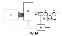
図1Aを参照すると、ジャカード(Jacquard)型の織機10上で織ることで繊維組織を得ることを示しているが、この織機10は、縦糸供給場所12から供給されて、繊維組織を引込マンドレル14上に送り出し、この繊維組織は続けて、様々な他の支持用のマンドレル、たとえば、逆方向マンドレル16や巻き取りマンドレル18などを介して、巻き上げ機まで搬送される。巻き取りマンドレルは、図1Bに示した巻き上げ機の巻き取りマンドレルを構成していてもよい。
Referring to FIG. 1A, it is shown that a fiber structure is obtained by weaving on a Jacquard
一度、繊維組織またはプリフォームが織られると、これは幾分ドライマットに似て、この後の移動のために巻き取りマンドレル上に送り出されて、次に、製造されるケースの内側輪郭に相当する外側輪郭を有する樹脂射出成形金型のマンドレル(以下、含浸マンドレルと参照する)上で複数回回転されて(典型的には、4回転とさらに1回転の1/4より小さい部分的回転で)巻き取られる。 Once the fiber structure or preform is woven, it somewhat resembles a dry mat and is sent out on a take-up mandrel for subsequent movement and then corresponds to the inner contour of the case to be manufactured Rotated several times on a mandrel (hereinafter referred to as an impregnated mandrel) of a resin injection mold having an outer contour to (typically 4 rotations and a partial rotation less than 1/4 of one rotation) ) Wound up.
含浸マンドレル上にプリフォームが保持される際、これは、樹脂とともに含浸処理される。この目的のため、プリフォームと組み合わせて、複数の部品に適用することでケースが成形されて、このように構成された型の中に樹脂が射出される。含浸処理は、プリフォームを内に含む型の内側と外側の間の圧力差を設定することで補助できる。含浸処理の後、樹脂を重合させるステップが行われる。 When the preform is held on the impregnation mandrel, it is impregnated with the resin. For this purpose, a case is formed by applying it to a plurality of parts in combination with a preform, and a resin is injected into the mold thus configured. The impregnation process can be assisted by setting a pressure difference between the inside and the outside of the mold containing the preform. After the impregnation treatment, a step of polymerizing the resin is performed.
巻き上げ機20は、このことを行うため、プリフォームの位置合わせと場合によっては中心からのずれとを実時間で監視し、巻き上げ機20自身は、特に、巻き取りマンドレル24と含浸マンドレル26を支持するスタンド22を含む。三次元製織することで得られるプリフォーム28を受け取る巻き取りマンドレル24は水平方向の軸30によって支持されているが、この軸30は一方の端部を巻き上げ機のスタンド22上に回転可能に取り付けており、かつ他方の端部を第1のモーター32の出力軸と結合させている。含浸マンドレル26は、巻き取りマンドレルから巻き出されるプリフォームの重なる層を受け取るが、これは、製造されるケースの内面の輪郭に相当する輪郭の外面を有し、含浸マンドレル26は、それ自体で水平方向の軸34によって支持され、この軸34は、巻き取りマンドレルの回転軸30と平行であり、かつ一方の端部をスタンド22上に回転可能に取り付けるとともに、この他方の端部を第2のモーター36の出力軸と結合している。巻き取りマンドレルと含浸マンドレルの間には、成形ロール38を備えていてもよい。
In order to do this, the hoisting
各マンドレルの回転速度を制御および監視するために、モーター32および36に対して制御ユニット40が接続されている。より一般的には、制御ユニットは、通常、中央処理装置400、記憶モジュール402、および入力/出力モジュール404(特に、画面406、キーボード408などを用いて作業するもの)などを含むように構成されており(図2参照)、巻き上げ機の全ての作業パラメーターを制御するように機能して、プリフォームを所定位置に置き(キャリブレーション段階)、次に巻き取られる(自動制御段階)。
A
本発明は、含浸段階を始める前に、プリフォームの巻き上げ作業の着手と巻き上げ作業を通じて(およびその前の織り作業の間)異常性を自動的に検出することを行う。本提案の解決策では、複数のカメラ42を所定位置に配置して、これらを画像解析モジュールと結合させて、プリフォームの下方で巻き上げ機(または織機)上に配設することで、プリフォームが移動する際に、プリフォームの隠された表面の画像を撮影できるようにして、引き起こされ得る異常性を検出できるようにしている。この設備は、プリフォームの表面を特徴付けることができ、この特徴付けたものを、不良のない参照として知られている参照用の織りパターンと比較できるようにしている。この不良のマップ化によって、実時間で不良を自動的に認識することを可能とし、不良が如何に重大であるかについての情報を作業者に与えることを可能にする。特に、不良が現れたときに、作業者に対して、取るべき行動について情報を与えることができる(たとえば、解析のために巻き上げを中止する、巻き上げを続行する、検出された不良に応じて修復を行うべくプリフォーム上で作業を行う、など)、または、全ての不良について正確に場所を特定して、これらの三次元的な(3D)位置をケース上で識別させて、巻き上げの終了時に、たとえば、それらは互いに近づき過ぎることはなく、それらは部品の欠陥のなさに影響を及ぼす虞がないことを立証、または、検出作業を向上させるべく、経時的に変化する不良の一覧表をつくるようにする。
The present invention automatically detects anomalies through the start of the preform winding operation and the winding operation (and during the previous weaving operation) before beginning the impregnation step. In the proposed solution, a plurality of
より具体的には、プリフォームの織りパターンを示すためと、作業場の照明によってもたらされる光の干渉によって影響を受けないようにするために、ライトボックス44内にカメラを配置するが、好適には、巻き上げ中のプリフォームに出来るだけ近づけるようにライトボックス44を配置して、機械の上方の作業場内の干渉的な照明や大気から、プリフォームの表面を隔離する。
More specifically, a camera is placed in the
図1Aおよび1Bを参照すると、ライトボックス44を取り付けることができる様々な場所を例示している。これらから理解できるように、ライトボックスをマンドレルと対面させるように配置するとき、好適には、マンドレルの輪郭と適合するようにライトボックスを形成する。
Referring to FIGS. 1A and 1B, various locations where the
さらに、カーボン繊維を用いて形成された織られたプリフォームの織りパターンによって示されるコントラストを増大させるため、したがって、異常性の様々な種類の識別を向上するため、好適には、青色の光(波長が446nmから500nmの範囲内に収まる)、または赤色の光(波長が620nmから800nmの範囲内に収まる)を用いる。 In addition, in order to increase the contrast exhibited by the weave pattern of the woven preform formed with carbon fibers, and thus improve the identification of various types of anomalies, preferably blue light ( The wavelength is within the range of 446 nm to 500 nm) or red light (the wavelength is within the range of 620 nm to 800 nm).
図2に示しているように、好適には制御ユニット40内に含められる画像解析モジュールは、それ自身で、カメラから送られる画像からプリフォームの複数の領域を同時に監視することができ、かつ、モジュール内に好適に記録されている参照用の織りパターンと比較したプリフォームの外観の差を検出することにより、これらの各々について織りパターン間を区別し、作業者に信号を送信して、不一致が生じる場合には、作業者が行動を起こすことを可能にしているが、特に、2つの織りパターンを比較した結果、少なくとも1つの監視された領域内で、プリフォームの織り中に汚染および/または不良の結果として異常性の存在を特徴付ける外観の差が認められた場合には、プリフォームの移送を停止させる。監視される領域の大きさ、位置、および数は、画像解析モジュール内のスキャン窓を用いて作業者によって定められて、プリフォームの全幅にわたって延在するストリップを全体的にカバーできるようにする。効果的には、均一な織りパターンを得るために、そのようなスキャン窓は、プリフォーム内で織られる追跡織糸(tracer yarn)の両側に置かれるように選択される。各カメラは、プリフォームの決定された領域に割り当てられ、したがって、1または2以上のスキャン窓をカバーできる。
As shown in FIG. 2, the image analysis module, preferably included in the
この目的のため、図2に示しているように、作業者はシステムを始める段階中(織りまたは巻き上げを開始するとき)に行動して、画像解析モジュールに適するグラフィックソフトウエアツールを用いて、プリフォームの画像上に直接的にこれらスキャン窓を形成する。これら窓は、好適には、欠陥がないと信じられている、つまり、汚染や不良がないと信じられているプリフォームのストリップ内に置かれるように選択される。作業者が監視画面406上の各スキャン窓内で欠陥がないプリフォーム領域の存在を観察するとき、作業者は、「参照取得」と呼ばれるステップを検証し、領域内に現れた検証された織りパターンが記憶される(プリフォームの与えられたストリップ用に、図3は、検証された欠陥がない領域50と、検証できない欠陥のある領域52を例示している)。パターンの差は、プリフォームの各領域の織りの変化の結果である。記憶されたデータは、画像内のグレイレベルのマップである。織りパターンは繰り返されるため、プリフォームの画像のグレイレベルの使用がこの測定値により可能となり、同様に繰り返されるグレイレベル曲線を得ることができる。巻き上げまたは織りの作業の間、グレイレベル曲線の外観の変化は、異常性として解釈される。
For this purpose, as shown in FIG. 2, the operator acts during the phase of starting the system (when weaving or winding is started) and uses a graphics software tool suitable for the image analysis module. These scan windows are formed directly on the reformed image. These windows are preferably selected to be placed in a strip of preform that is believed to be free of defects, that is, believed to be free of contamination and defects. As the operator observes the presence of a preform region that is free of defects within each scan window on the
検出された汚染の例が図4に示されているが、これは特に、巻き上げ機上にプリフォームを所定位置に配置するときに、作業者によって忘れられた粘着テープの一部54を示している。同図から明確に理解できるように、不良の領域56について参照用の織りパターンと比較すると、グレイレベル曲線58の解析の結果、プリフォームの織りパターンに変化が存在する。この検出の種類は、汚染の種類の異常性(Scotch(R)テープ、Kevlar(R)繊維、短い繊維など)、かつほとんどの織り不良を検出することを可能とするが、たとえば、浮き縦糸、浮き横糸、長い浮き糸または”織りミス”、ループ、切れたトレーサ糸、切れた縦糸、失われた織糸または”ピック”、二重織糸または”ピック”、部分的に失われた織糸(部分的に失われたピック)、縮れた織糸などを含む。図示した例では、検出モードは、検出ライン(広い水平方向のライン60、62)に沿って記載されているが、しかしながら、このモジュールは、スキャン窓と同等の検出領域にわたって織りパターン内の変化を監視することが本来的に可能であるため、必要に応じて、最も高感度な検出モードを提供できる。グレイレベルと軸方向位置に関する検出閾値は、織りパターンの「通常」の変化に適応するように設定することも可能である。
An example of detected contamination is shown in FIG. 4, which shows a
織りおよび/または巻き上げ作業の質を追跡するために、異常性を処理し、これらを統計的に解析するために様々なステップが行われるが、巻き上げ機の例について図5を参照して以下に詳述する。一度、初期化段階が完了すると(ステップ100)、プリフォームの巻き上げが着手されて、画像解析モジュールが異常性を検出するまで続けられる(ステップ102)。異常性が現れると、巻き上げ作業は停止されて、検出された異常性について監視画面が固定される。この異常性には、自動的に整理番号が採番され、その位置が異常性の画像と共に記憶されて、作業者に対して、前もって記憶されている様々な種類の異常性の中からその異常性についてラベルを選択することが勧められる(ステップ104)。作業者は次に、プリフォームに直接的に介入して、その異常性を直接的に観察し(ステップ106)、それが修復可能か否かを決定する(ステップ108のテスト)。このテストの答えが「イエス」の場合、修復が実行されて(ステップ110)、自動的に修復の整理番号が採番されて、実行されている修復の画像と共に記憶されて、作業者に対して前もって記憶されている様々な種類の修復の中から修復のラベルを選択することが勧められる(ステップ112)。次に、巻き上げを再開始することが可能となる(潜在的な新しい異常性を検出するため、ステップ102に戻る)。一方、ステップ108において、テストに対する答えが「ノー」の場合、専門家を呼ぶことを必要とし(ステップ114)、その異常性が重大か否かを決定する(ステップ116のテスト)、つまり、その異常性が巻き上げ作業の停止を必要とする性質のもの(ステップ118)であり、プリフォームをはねるべきなのかについて決定する。一方、その異常性が許容できるものであれば、巻き上げを再開始可能になる(ステップ102に戻る)。巻き上げ作業の終了時に、異常性が認識されたことと、それらが修復されたことを示す解析レポートを発行してもよい。好適には、そのレポートは、図6Aに示したような三次元状でケースを表示する表現で行ってもよく、または、図6Bに示した展開した表現で行ってもよく、様々な異常性について、それらが修復されたか否かにかかわらず、それらの位置をそれらの整理番号と共に表示させてもよい。この図形表示は、異常性の修復と異常性の種類について良好な視認を可能にする。この結果、決定をより速く行えるように、仕様との背反を処理するサイクルにおける時間を相当に節約することができる。本発明によって得られる異常性のマップ(織りおよび/または巻き上げの異常性)を、超音波監視を行って観察された不良のマップと比較する(重ね合わせる)ことで、さらに有利にマップを構成することは可能である。 In order to track the quality of the weaving and / or hoisting operations, various steps are taken to deal with anomalies and to analyze them statistically, with reference to FIG. Detailed description. Once the initialization phase is complete (step 100), the preform winding is initiated and continues until the image analysis module detects anomalies (step 102). When the abnormality appears, the winding operation is stopped and the monitoring screen is fixed for the detected abnormality. For this anomaly, a reference number is automatically assigned, the position is stored with the anomaly image, and the anomaly is selected from various types of anomalies previously stored for the operator. It is recommended to select a label for gender (step 104). The operator then intervenes directly in the preform and directly observes the anomaly (step 106) and determines whether it can be repaired (test in step 108). If the answer to this test is “yes”, the repair is performed (step 110), and the repair reference number is automatically numbered and stored with the image of the repair being performed for the operator. It is recommended to select a repair label from among the various types of repairs previously stored (step 112). The winding can then be restarted (return to step 102 to detect potential new anomalies). On the other hand, if the answer to the test is “no” at step 108, it is necessary to call an expert (step 114) and determine if the anomaly is critical (test at step 116), that is, A determination is made as to whether the anomaly is of a nature that requires stopping the hoisting operation (step 118) and the preform should be rebounded. On the other hand, if the abnormality is acceptable, the winding can be restarted (return to step 102). At the end of the winding work, an analysis report may be issued indicating that anomalies have been recognized and that they have been repaired. Preferably, the report may be in a three-dimensional representation of the case as shown in FIG. 6A, or in an expanded representation as shown in FIG. , Their positions may be displayed along with their reference numbers regardless of whether they have been repaired. This graphical display allows for good visibility of anomaly repair and anomaly types. As a result, considerable time can be saved in the cycle of dealing with conflicting specifications so that decisions can be made faster. The map of anomalies (weaving and / or roll-up anomalies) obtained by the present invention is compared with the map of defects observed by supersonic monitoring (overlaying) to further advantageously construct the map. It is possible.
Claims (10)
Applications Claiming Priority (3)
| Application Number | Priority Date | Filing Date | Title |
|---|---|---|---|
| FR1353888A FR3005042B1 (en) | 2013-04-26 | 2013-04-26 | WEAVING OR WINDING MACHINE FOR FIBROUS TEXTURE FOR ANOMALY CONTROL BY IMAGE ANALYSIS |
| FR1353888 | 2013-04-26 | ||
| PCT/FR2014/050956 WO2014174193A1 (en) | 2013-04-26 | 2014-04-18 | Machine for weaving or winding a fibrous texture that allows checks for anamoly to be made using image analysis |
Publications (2)
| Publication Number | Publication Date |
|---|---|
| JP2016518276A JP2016518276A (en) | 2016-06-23 |
| JP6580556B2 true JP6580556B2 (en) | 2019-09-25 |
Family
ID=48782450
Family Applications (1)
| Application Number | Title | Priority Date | Filing Date |
|---|---|---|---|
| JP2016509523A Active JP6580556B2 (en) | 2013-04-26 | 2014-04-18 | Method for inspecting abnormalities by image analysis |
Country Status (9)
| Country | Link |
|---|---|
| US (1) | US9726616B2 (en) |
| EP (1) | EP2989449B1 (en) |
| JP (1) | JP6580556B2 (en) |
| CN (1) | CN105164519B (en) |
| BR (1) | BR112015027152B1 (en) |
| CA (1) | CA2910555C (en) |
| FR (1) | FR3005042B1 (en) |
| RU (1) | RU2655816C2 (en) |
| WO (1) | WO2014174193A1 (en) |
Families Citing this family (24)
| Publication number | Priority date | Publication date | Assignee | Title |
|---|---|---|---|---|
| FR3033046B1 (en) * | 2015-02-23 | 2019-06-14 | Safran Aircraft Engines | METHOD AND DEVICE FOR CONTROLLING THE STATUS OF A REMOTE AIRCRAFT ENGINE |
| FR3048435B1 (en) * | 2016-03-02 | 2018-04-06 | Safran Aircraft Engines | INSTALLATION AND METHOD FOR MANUFACTURING FIBROUS BAND-SHAPED TEXTURE HAVING IN THE CROSS-SECTIONAL SECTION AN EVOLVING PROFILE |
| JP6406304B2 (en) * | 2016-04-12 | 2018-10-17 | トヨタ自動車株式会社 | Measuring device for measuring winding angle of carbon fiber wound around base material to base material and measuring method of the winding angle |
| FR3055111B1 (en) | 2016-08-16 | 2018-08-31 | Safran Aircraft Engines | INSTALLATION AND METHOD FOR SHAPING A FIBROUS REVOLUTION PREFORM HAVING A RADIAL SECTION FOR AN EVOLVING PROFILE |
| FR3055110B1 (en) * | 2016-08-16 | 2018-08-31 | Safran Aircraft Engines | INSTALLATION AND METHOD FOR SHAPING A FIBROUS REVOLUTION PREFORM HAVING A RADIAL SECTION FOR AN EVOLVING PROFILE |
| WO2018117790A1 (en) * | 2016-12-20 | 2018-06-28 | Tinajero Aguirre Luis Fernando | Method for manufacturing aerospace turbine housings |
| JP6787211B2 (en) * | 2017-03-24 | 2020-11-18 | トヨタ自動車株式会社 | Filament winding device |
| EP3662283A1 (en) * | 2017-09-14 | 2020-06-10 | Uster Technologies AG | Fiber blend identification and/or ratio measurement |
| FR3093297B1 (en) * | 2019-02-28 | 2022-08-12 | Safran Aircraft Engines | METHOD FOR MAKING A WOVEN PIECE TAKING ACCOUNT OF OFF-FRAME |
| CN111761840B (en) * | 2019-04-01 | 2022-02-01 | 中国航发商用航空发动机有限责任公司 | Fiber fabric winding system and winding deformation control method |
| IT201900005826A1 (en) * | 2019-04-16 | 2020-10-16 | Santex Rimar Group S R L | DEVICE AND METHOD FOR REAL TIME DETECTION OF DEFECTS IN FABRICS, DURING WEAVING |
| IT201900016127A1 (en) * | 2019-09-12 | 2021-03-12 | Manteco S P A | Textile control and management system |
| US11685104B2 (en) | 2019-12-20 | 2023-06-27 | Industrial Technology Research Institute | Dynamic correcting system of manufacturing process using wire and dynamic correcting method using the same |
| TW202204713A (en) * | 2020-02-05 | 2022-02-01 | 葡萄牙商斯馬特克斯一人有限公司 | Systems and methods for defect detection |
| FR3107853B1 (en) * | 2020-03-03 | 2023-05-26 | Safran Aircraft Engines | DEFRAME MEASUREMENT IN A PREFORM WRAPPED ON A DRUM OF AN INJECTION MOLD |
| FR3116754B1 (en) * | 2020-12-01 | 2023-04-14 | Safran Aircraft Engines | DEFRAME CONTROL IN A PREFORM WRAPPED ON A DRUM OF AN INJECTION MOLD |
| TWI772991B (en) | 2020-12-02 | 2022-08-01 | 財團法人工業技術研究院 | Braiding path generation method and device, and dynamic correction method and braiding system |
| CN112734184B (en) * | 2020-12-30 | 2022-06-03 | 南通汉腾建筑科技有限公司 | Acceptance method and system for assembly type building |
| CN113433137B (en) * | 2021-08-26 | 2022-01-18 | 南通三田纺织有限公司 | Textile cloth surface flaw detection device based on YOLO neural network |
| FR3127042A1 (en) * | 2021-09-15 | 2023-03-17 | Safran Aircraft Engines | Process for checking woven parts of a turbomachine |
| FR3135096B1 (en) * | 2022-04-27 | 2024-04-05 | Safran | JACQUARD TYPE WEAVING Loom FOR THE MANUFACTURE OF A WOVEN PREFORM |
| FR3140575A1 (en) * | 2022-10-07 | 2024-04-12 | Safran Nacelles | Device and method for detecting an anomaly during the manufacture of a composite part by automatic draping |
| CN115816878B (en) * | 2023-01-09 | 2023-07-07 | 浙江恒亿达复合材料有限公司 | Glass carbon fiber pultrusion plate preforming die and process |
| CN116805312B (en) * | 2023-08-21 | 2024-01-05 | 青岛时佳汇服装有限公司 | Knitted fabric quality detection method based on image processing |
Family Cites Families (30)
| Publication number | Priority date | Publication date | Assignee | Title |
|---|---|---|---|---|
| DE2853258A1 (en) * | 1978-12-09 | 1980-06-12 | Hoesch Werke Ag | METHOD AND ARRANGEMENT FOR APPLYING A MARKING ON THE SURFACE OF MOVING TABLES AND TAPES |
| DE3926346A1 (en) * | 1989-08-09 | 1991-02-14 | Rieter Ag Maschf | METHOD AND DEVICE FOR DETERMINING FIBER MATERIAL POLLUTED WITH FOREIGN BODIES |
| US5224047A (en) * | 1989-10-03 | 1993-06-29 | Murata Kikai Kabushiki Kaisha | Maintenance monitoring apparatus for automatic winder |
| US6741726B1 (en) * | 1994-03-10 | 2004-05-25 | Lawson-Hemphill, Inc. | System and method for electronically evaluating predicted fabric qualities |
| JP3063719B2 (en) * | 1997-12-24 | 2000-07-12 | 東洋紡績株式会社 | Woven cloth inspection equipment |
| DE19906701C1 (en) * | 1999-02-18 | 2000-12-14 | Parsytec Comp Gmbh | Method and device for detecting, marking and retrieving defects in a material strip |
| US6650779B2 (en) * | 1999-03-26 | 2003-11-18 | Georgia Tech Research Corp. | Method and apparatus for analyzing an image to detect and identify patterns |
| US6299730B1 (en) * | 1999-09-20 | 2001-10-09 | The Mead Corporation | Method and system for monitoring web defects along a moving paper web |
| US6633383B1 (en) * | 1999-10-25 | 2003-10-14 | Linetech Industries, Inc. | Method and apparatus for the automated inspection of yarn packages |
| US6750466B2 (en) * | 2001-02-09 | 2004-06-15 | Wintriss Engineering Corporation | Web inspection system |
| BE1014133A3 (en) * | 2001-04-20 | 2003-05-06 | Picanol Nv | Method for optimizing a textile production and establishments to apply this procedure. |
| JP3982809B2 (en) * | 2002-09-06 | 2007-09-26 | 津田駒工業株式会社 | Defect display device for looms |
| DE10347240B4 (en) * | 2003-10-10 | 2015-10-15 | Trützschler GmbH & Co Kommanditgesellschaft | Apparatus in the spinning preparation for detecting foreign parts made of plastic in fiber flakes |
| CN100485371C (en) * | 2005-12-01 | 2009-05-06 | 渤海船舶重工有限责任公司 | Automatic online detection method for defects on upper and lower surfaces during steel plate pretreatment process |
| US20090218380A1 (en) * | 2006-02-08 | 2009-09-03 | Prittie Allan R | Web Inspection and Repair Machine with Retractable Inspection Zone |
| JP2007291535A (en) * | 2006-04-21 | 2007-11-08 | Toray Ind Inc | Apparatus and method for inspecting carbon fiber fabric |
| US8050486B2 (en) * | 2006-05-16 | 2011-11-01 | The Boeing Company | System and method for identifying a feature of a workpiece |
| FR2913053B1 (en) | 2007-02-23 | 2009-05-22 | Snecma Sa | PROCESS FOR MANUFACTURING A GAS TURBINE CASE OF COMPOSITE MATERIAL AND CARTER THUS OBTAINED |
| CN100593716C (en) * | 2007-11-09 | 2010-03-10 | 无锡东望科技有限公司 | On-line detecting method of machine vision system for printed calico flaw |
| CN201177605Y (en) * | 2008-01-31 | 2009-01-07 | 稳健实业(深圳)有限公司 | Piece goods detection device |
| CN201242529Y (en) * | 2008-06-19 | 2009-05-20 | 何峰 | Apparatus for monitoring circular knitting machine on-line quality based on computer pattern recognition principle |
| FR2936605B1 (en) * | 2008-10-01 | 2014-10-31 | Saint Gobain | DEVICE FOR ANALYZING THE SURFACE OF A SUBSTRATE |
| FI121859B (en) * | 2008-11-25 | 2011-05-13 | Metso Automation Oy | A method for controlling the repair of a web with a rolling machine and corresponding system |
| CN101988905B (en) * | 2009-08-07 | 2014-04-30 | 深圳劲嘉彩印集团股份有限公司 | Printing product detection equipment |
| CN101923059A (en) * | 2010-04-15 | 2010-12-22 | 北京经纬纺机新技术有限公司 | Automatic cloth inspection method and system |
| WO2012137129A1 (en) * | 2011-04-05 | 2012-10-11 | Elbit Vision Systems (Evs) Ltd. | On-loom fabric inspection system and method |
| FR2974026B1 (en) | 2011-04-13 | 2014-09-19 | Snecma | MACHINE FOR WINDING A FIBROUS TEXTURE ON AN IMPREGNATION CHUCK |
| CN202533374U (en) * | 2011-12-16 | 2012-11-14 | 章敬文 | Surface defect detection system for aluminum foil |
| CN202676614U (en) * | 2012-06-14 | 2013-01-16 | 孙征 | Automatic product appearance detecting system |
| FR2995555B1 (en) * | 2012-09-17 | 2017-11-24 | Snecma | FIBROUS TEXTURE WINDING MACHINE FOR IMAGE ANALYSIS ALIGNMENT AND DECADING CONTROL |
-
2013
- 2013-04-26 FR FR1353888A patent/FR3005042B1/en active Active
-
2014
- 2014-04-18 RU RU2015150420A patent/RU2655816C2/en active
- 2014-04-18 US US14/787,142 patent/US9726616B2/en active Active
- 2014-04-18 JP JP2016509523A patent/JP6580556B2/en active Active
- 2014-04-18 BR BR112015027152-9A patent/BR112015027152B1/en active IP Right Grant
- 2014-04-18 CN CN201480023539.7A patent/CN105164519B/en active Active
- 2014-04-18 CA CA2910555A patent/CA2910555C/en active Active
- 2014-04-18 WO PCT/FR2014/050956 patent/WO2014174193A1/en active Application Filing
- 2014-04-18 EP EP14722298.8A patent/EP2989449B1/en active Active
Also Published As
| Publication number | Publication date |
|---|---|
| FR3005042A1 (en) | 2014-10-31 |
| CA2910555A1 (en) | 2014-10-30 |
| EP2989449B1 (en) | 2020-04-08 |
| RU2015150420A (en) | 2017-06-02 |
| US20160077019A1 (en) | 2016-03-17 |
| RU2655816C2 (en) | 2018-05-29 |
| BR112015027152B1 (en) | 2020-11-24 |
| WO2014174193A1 (en) | 2014-10-30 |
| RU2015150420A3 (en) | 2018-03-26 |
| FR3005042B1 (en) | 2016-01-01 |
| CN105164519A (en) | 2015-12-16 |
| BR112015027152A2 (en) | 2017-07-25 |
| CA2910555C (en) | 2021-04-20 |
| CN105164519B (en) | 2019-01-18 |
| JP2016518276A (en) | 2016-06-23 |
| EP2989449A1 (en) | 2016-03-02 |
| US9726616B2 (en) | 2017-08-08 |
Similar Documents
| Publication | Publication Date | Title |
|---|---|---|
| JP6580556B2 (en) | Method for inspecting abnormalities by image analysis | |
| JP6235594B2 (en) | Machine for winding fibrous materials that allows alignment and eccentricity control through image analysis | |
| CN104915635B (en) | Check the method and computer system, computer-readable medium of composite article | |
| CN102224096B (en) | Quality monitoring of splices in an elongated textile test material | |
| EP3717685B1 (en) | Methods and systems for triggered on-loom fabric inspection | |
| US20070173966A1 (en) | Visual fiber placement inspection | |
| ES2910145T3 (en) | Procedure and equipment to determine defects in fibrous materials | |
| EP3396484B1 (en) | Process control of a composite fabrication process | |
| JP5505588B2 (en) | Filament winding equipment | |
| JP2015524750A (en) | Method and system for cutting preforms for the manufacture of turbomachine parts | |
| CN113544496A (en) | Apparatus and method for real-time identification of defects in a fabric during weaving | |
| TW201632687A (en) | Inspection system for identifying defects in braided cords | |
| JP2014202534A (en) | Rotor blade measuring device and rotor blade measuring method | |
| JP2010230595A (en) | Rotor inspection device and computer program | |
| CN114563412A (en) | Bogie assembling quality detection method | |
| CN112391731B (en) | Online detection method for yarn breakage during weaving of warp knitting machine | |
| KR102262091B1 (en) | Method for probing the defects and preventing the failure of military machines and civil structures on a real-time basis | |
| KR101872934B1 (en) | Positional positioning method using RoleMap organized by loom stop and weft bad position information | |
| İkiz et al. | Digitizing and classifying woven fabric defects | |
| FR3140383A1 (en) | Device for monitoring weaving using deformation sensors | |
| WO2012063206A2 (en) | Fault prevention system and method for tufting machines | |
| KR20120002599U (en) | Operation apparatus of warping and beaming of volume controlmethod | |
| JPH07126964A (en) | Apparatus for inspecting woven fabric |
Legal Events
| Date | Code | Title | Description |
|---|---|---|---|
| A521 | Request for written amendment filed |
Free format text: JAPANESE INTERMEDIATE CODE: A523 Effective date: 20151225 |
|
| A621 | Written request for application examination |
Free format text: JAPANESE INTERMEDIATE CODE: A621 Effective date: 20170328 |
|
| A977 | Report on retrieval |
Free format text: JAPANESE INTERMEDIATE CODE: A971007 Effective date: 20180315 |
|
| A131 | Notification of reasons for refusal |
Free format text: JAPANESE INTERMEDIATE CODE: A131 Effective date: 20180424 |
|
| A521 | Request for written amendment filed |
Free format text: JAPANESE INTERMEDIATE CODE: A523 Effective date: 20180621 |
|
| A131 | Notification of reasons for refusal |
Free format text: JAPANESE INTERMEDIATE CODE: A131 Effective date: 20181113 |
|
| A521 | Request for written amendment filed |
Free format text: JAPANESE INTERMEDIATE CODE: A523 Effective date: 20190206 |
|
| TRDD | Decision of grant or rejection written | ||
| A01 | Written decision to grant a patent or to grant a registration (utility model) |
Free format text: JAPANESE INTERMEDIATE CODE: A01 Effective date: 20190730 |
|
| A61 | First payment of annual fees (during grant procedure) |
Free format text: JAPANESE INTERMEDIATE CODE: A61 Effective date: 20190828 |
|
| R150 | Certificate of patent or registration of utility model |
Ref document number: 6580556 Country of ref document: JP Free format text: JAPANESE INTERMEDIATE CODE: R150 |
|
| R250 | Receipt of annual fees |
Free format text: JAPANESE INTERMEDIATE CODE: R250 |
|
| R250 | Receipt of annual fees |
Free format text: JAPANESE INTERMEDIATE CODE: R250 |