JP6580265B2 - Retraction device for movable furniture parts - Google Patents
Retraction device for movable furniture parts Download PDFInfo
- Publication number
- JP6580265B2 JP6580265B2 JP2018526243A JP2018526243A JP6580265B2 JP 6580265 B2 JP6580265 B2 JP 6580265B2 JP 2018526243 A JP2018526243 A JP 2018526243A JP 2018526243 A JP2018526243 A JP 2018526243A JP 6580265 B2 JP6580265 B2 JP 6580265B2
- Authority
- JP
- Japan
- Prior art keywords
- entrainment
- guide
- drawer
- sleeve
- entrainment body
- Prior art date
- Legal status (The legal status is an assumption and is not a legal conclusion. Google has not performed a legal analysis and makes no representation as to the accuracy of the status listed.)
- Active
Links
Images


Classifications
-
- A—HUMAN NECESSITIES
- A47—FURNITURE; DOMESTIC ARTICLES OR APPLIANCES; COFFEE MILLS; SPICE MILLS; SUCTION CLEANERS IN GENERAL
- A47B—TABLES; DESKS; OFFICE FURNITURE; CABINETS; DRAWERS; GENERAL DETAILS OF FURNITURE
- A47B88/00—Drawers for tables, cabinets or like furniture; Guides for drawers
- A47B88/40—Sliding drawers; Slides or guides therefor
- A47B88/453—Actuated drawers
- A47B88/46—Actuated drawers operated by mechanically-stored energy, e.g. by springs
- A47B88/467—Actuated drawers operated by mechanically-stored energy, e.g. by springs self-closing
-
- A—HUMAN NECESSITIES
- A47—FURNITURE; DOMESTIC ARTICLES OR APPLIANCES; COFFEE MILLS; SPICE MILLS; SUCTION CLEANERS IN GENERAL
- A47B—TABLES; DESKS; OFFICE FURNITURE; CABINETS; DRAWERS; GENERAL DETAILS OF FURNITURE
- A47B88/00—Drawers for tables, cabinets or like furniture; Guides for drawers
- A47B88/40—Sliding drawers; Slides or guides therefor
- A47B88/437—Rollers for slides or guides
-
- A—HUMAN NECESSITIES
- A47—FURNITURE; DOMESTIC ARTICLES OR APPLIANCES; COFFEE MILLS; SPICE MILLS; SUCTION CLEANERS IN GENERAL
- A47B—TABLES; DESKS; OFFICE FURNITURE; CABINETS; DRAWERS; GENERAL DETAILS OF FURNITURE
- A47B88/00—Drawers for tables, cabinets or like furniture; Guides for drawers
- A47B88/40—Sliding drawers; Slides or guides therefor
- A47B88/49—Sliding drawers; Slides or guides therefor with double extensible guides or parts
-
- E—FIXED CONSTRUCTIONS
- E05—LOCKS; KEYS; WINDOW OR DOOR FITTINGS; SAFES
- E05F—DEVICES FOR MOVING WINGS INTO OPEN OR CLOSED POSITION; CHECKS FOR WINGS; WING FITTINGS NOT OTHERWISE PROVIDED FOR, CONCERNED WITH THE FUNCTIONING OF THE WING
- E05F1/00—Closers or openers for wings, not otherwise provided for in this subclass
- E05F1/08—Closers or openers for wings, not otherwise provided for in this subclass spring-actuated, e.g. for horizontally sliding wings
- E05F1/16—Closers or openers for wings, not otherwise provided for in this subclass spring-actuated, e.g. for horizontally sliding wings for sliding wings
-
- E—FIXED CONSTRUCTIONS
- E05—LOCKS; KEYS; WINDOW OR DOOR FITTINGS; SAFES
- E05F—DEVICES FOR MOVING WINGS INTO OPEN OR CLOSED POSITION; CHECKS FOR WINGS; WING FITTINGS NOT OTHERWISE PROVIDED FOR, CONCERNED WITH THE FUNCTIONING OF THE WING
- E05F5/00—Braking devices, e.g. checks; Stops; Buffers
- E05F5/003—Braking devices, e.g. checks; Stops; Buffers for sliding wings
-
- E—FIXED CONSTRUCTIONS
- E05—LOCKS; KEYS; WINDOW OR DOOR FITTINGS; SAFES
- E05F—DEVICES FOR MOVING WINGS INTO OPEN OR CLOSED POSITION; CHECKS FOR WINGS; WING FITTINGS NOT OTHERWISE PROVIDED FOR, CONCERNED WITH THE FUNCTIONING OF THE WING
- E05F5/00—Braking devices, e.g. checks; Stops; Buffers
- E05F5/02—Braking devices, e.g. checks; Stops; Buffers specially for preventing the slamming of swinging wings during final closing movement, e.g. jamb stops
- E05F5/027—Braking devices, e.g. checks; Stops; Buffers specially for preventing the slamming of swinging wings during final closing movement, e.g. jamb stops with closing action
-
- A—HUMAN NECESSITIES
- A47—FURNITURE; DOMESTIC ARTICLES OR APPLIANCES; COFFEE MILLS; SPICE MILLS; SUCTION CLEANERS IN GENERAL
- A47B—TABLES; DESKS; OFFICE FURNITURE; CABINETS; DRAWERS; GENERAL DETAILS OF FURNITURE
- A47B88/00—Drawers for tables, cabinets or like furniture; Guides for drawers
- A47B88/40—Sliding drawers; Slides or guides therefor
- A47B88/453—Actuated drawers
- A47B88/46—Actuated drawers operated by mechanically-stored energy, e.g. by springs
- A47B88/47—Actuated drawers operated by mechanically-stored energy, e.g. by springs having both self-opening and self-closing mechanisms which interact with each other
-
- E—FIXED CONSTRUCTIONS
- E05—LOCKS; KEYS; WINDOW OR DOOR FITTINGS; SAFES
- E05Y—INDEXING SCHEME RELATING TO HINGES OR OTHER SUSPENSION DEVICES FOR DOORS, WINDOWS OR WINGS AND DEVICES FOR MOVING WINGS INTO OPEN OR CLOSED POSITION, CHECKS FOR WINGS AND WING FITTINGS NOT OTHERWISE PROVIDED FOR, CONCERNED WITH THE FUNCTIONING OF THE WING
- E05Y2400/00—Electronic control; Power supply; Power or signal transmission; User interfaces
- E05Y2400/10—Electronic control
- E05Y2400/52—Safety arrangements
- E05Y2400/53—Wing impact prevention or reduction
- E05Y2400/54—Obstruction or resistance detection
- E05Y2400/55—Obstruction or resistance detection by using load sensors
-
- E—FIXED CONSTRUCTIONS
- E05—LOCKS; KEYS; WINDOW OR DOOR FITTINGS; SAFES
- E05Y—INDEXING SCHEME RELATING TO HINGES OR OTHER SUSPENSION DEVICES FOR DOORS, WINDOWS OR WINGS AND DEVICES FOR MOVING WINGS INTO OPEN OR CLOSED POSITION, CHECKS FOR WINGS AND WING FITTINGS NOT OTHERWISE PROVIDED FOR, CONCERNED WITH THE FUNCTIONING OF THE WING
- E05Y2800/00—Details, accessories and auxiliary operations not otherwise provided for
- E05Y2800/20—Combinations of elements
- E05Y2800/23—Combinations of elements of elements of different categories
- E05Y2800/24—Combinations of elements of elements of different categories of springs and brakes
-
- E—FIXED CONSTRUCTIONS
- E05—LOCKS; KEYS; WINDOW OR DOOR FITTINGS; SAFES
- E05Y—INDEXING SCHEME RELATING TO HINGES OR OTHER SUSPENSION DEVICES FOR DOORS, WINDOWS OR WINGS AND DEVICES FOR MOVING WINGS INTO OPEN OR CLOSED POSITION, CHECKS FOR WINGS AND WING FITTINGS NOT OTHERWISE PROVIDED FOR, CONCERNED WITH THE FUNCTIONING OF THE WING
- E05Y2900/00—Application of doors, windows, wings or fittings thereof
- E05Y2900/20—Application of doors, windows, wings or fittings thereof for furnitures, e.g. cabinets
Description
本発明は、可動に支持された家具部分を家具本体に対して相対的に、閉鎖された終端位置に引き込む引込み装置であって、
可動の家具部分と離脱可能に連結可能な連行体と、
連行体の引出し方向とは逆向きに連行体に力を加える少なくとも1つのばね装置であって、連行体とは別体のばね保持体を介して連行体の引出し方向において緊張可能であるばね装置と、
連行体とばね保持体との間において運動を連結する連結装置であって、連行体に対して相対的な、ばね保持体におけるばね装置の固定箇所の間隔を、引出し方向における連行体の引出し時に変化させる連結装置と、
を備える引込み装置に関する。
The present invention is a retraction device that draws a movably supported furniture portion relative to the furniture body into a closed end position,
An entrainment that can be removably connected to the movable furniture part;
At least one spring device that applies force to the entrained body in a direction opposite to the pulling-out direction of the entrained body, the spring device being tensionable in the pull-out direction of the entrained body via a spring holding body that is separate from the entrained body When,
A coupling device for coupling movement between the entrainment body and the spring holding body, wherein the distance between the fixed positions of the spring device relative to the entrainment body is determined when the entrainment body is pulled out in the pull-out direction. A coupling device to change,
It is related with a drawing-in device provided with.
さらに本発明は、記載される形式の引込み装置を備えた引出し用引出しガイド、ならびに、特にフラップ、扉または引出しである可動に支持された家具部分と、可動の家具部分を家具本体に対して相対的に、閉鎖された終端位置に引き込むこのような引込み装置と、を備えた装置に関する。 The invention further relates to a drawer drawer guide with a retractor of the type described, as well as a movably supported furniture part, in particular a flap, door or drawer, and the movable furniture part relative to the furniture body. In particular, it relates to a device comprising such a retraction device for retraction to a closed end position.
引込み装置は、特に引出しまたはスライド扉と共に使用される。この引出しまたはスライド扉は、その引出し範囲の大部分にわたって自由に走行可能であり、かつ閉鎖運動の終了近くで引込み装置の連行体によって捕捉され、ばね力によって閉鎖された終端位置に引き込まれ、かつそこで予め設定された閉鎖力で保持される。可動の家具部分の開放時には、使用者がまず、引張り動作によって、引込み装置のばね抵抗に抗して力を加えることが必要である。この動作は、連行体が予め設定された距離の後で可動の家具部分から連結遮断され、予荷重を加えられた休止位置に移動されるまで続けられる。この休止位置において、ばねは緊張した準備位置において静止し、その結果、次の閉鎖過程時に、可動の家具部分を新たに引き込むことができる。使用者は、引出しの開放運動時における連行体の連結解除を、しばしば急激な運動およびクリックノイズによって気付くことができる。なぜなら、急なばね切離し力(Federabrisskraft)に基づいて引出しは自由に可動になり、かつ予め加えられた引張り力に基づいて開放方向に加速されるからである。 Retraction devices are used in particular with drawers or sliding doors. The drawer or sliding door is free to travel over most of its drawer range and is captured by a retractor entrainment near the end of the closing movement, pulled into a closed end position by a spring force, and Therefore, it is held with a preset closing force. When opening the movable furniture part, the user must first apply a force against the spring resistance of the retractor by a pulling action. This operation continues until the entrainment body is disconnected from the movable furniture part after a predetermined distance and moved to a preloaded rest position. In this resting position, the spring rests in a tensioned preparation position, so that the movable furniture part can be newly retracted during the next closing process. The user can notice the disconnection of the entrained body during the opening movement of the drawer, often by sudden movements and click noise. This is because the drawer is freely movable based on a sudden spring separating force (Federabrisskraft) and accelerated in the opening direction based on a pre-applied tensile force.
本出願人の国際公開第2011/150432号は、この問題を、連行体とは別体のばね保持体によって解決しており、このばね保持体は、制御カムに沿って移動可能に案内されている。連行体およびばね保持体は、互いに係合し合う歯列として形成された連結装置を介して、互いに運動連結されて結合されている。ばね装置の緊張時(つまり可動の家具部分の開放時)に、ばね保持体におけるばね装置の固定箇所が、引出し方向に走行する連行体の位置に対して後退し、その結果、ばね装置の固定箇所の移動が連行体の移動よりも遅くなる。これによって、ばね装置のチャージが、減少したエネルギ消費と共に行われ、これにより、連行体の連結遮断時における望ましくないばね切離しと、連行体の連結遮断時における可動の家具部分の、これに関連した過度の加速とを、阻止することができる。この構造の欠点としては、互いに係合し合う歯列のために、引込み装置の構造高さを比較的大きく寸法設定しなければならないことがある。 Applicant's International Publication No. 2011/150432 solves this problem by a spring holder separate from the entrainment body, which is guided to move along the control cam. Yes. The entrainment body and the spring holding body are coupled to each other in a moving manner via a coupling device formed as a tooth row engaging with each other. When the spring device is tensioned (that is, when the movable furniture part is opened), the fixing position of the spring device in the spring holder moves backward with respect to the position of the entrained body that runs in the pull-out direction, and as a result, the spring device is fixed. The movement of the location is slower than the movement of the entrained body. This allows the spring device to be charged with a reduced energy consumption, which is related to the undesired spring separation when the entrainment is disconnected and the movable furniture part when the entrainment is disconnected. Excessive acceleration can be prevented. A disadvantage of this structure is that the structural height of the retractor must be sized relatively large because of the teeth that engage each other.
本発明の課題は、冒頭に述べた形式の引込み装置を改良して、コンパクトな構造形式を備えた引込み装置を提供することである。 The object of the present invention is to improve the retractor of the type described at the outset and to provide a retractor with a compact construction type.
この課題は、請求項1に記載の特徴によって解決される。本発明の別の好適な構成は、従属請求項に記載されている。 This problem is solved by the features of claim 1. Further preferred configurations of the invention are described in the dependent claims.
すなわち、本発明によれば、連結装置は、引出し方向に延びる長手方向軸線を有する少なくとも1つの制御エレメントを有しており、制御エレメントは、引出し方向における連行体の引出し時に、固定箇所と連行体との間に存在する間隔を変化させるために、少なくとも部分的に長手方向軸線を中心にして回転することが提案される。 That is, according to the present invention, the coupling device has at least one control element having a longitudinal axis extending in the pull-out direction, and the control element is fixed to the fixed portion and the pull-in body when the entrainment body is pulled out in the pull-out direction. In order to change the spacing existing between the two, it is proposed to rotate at least partly about the longitudinal axis.
このように構成されていると、連行体とばね保持体におけるばね装置の固定箇所との間の運動連結のために、力低減機構として形成された、制御エレメントを備えた連結装置が設けられており、この制御エレメントは、連行体の引出し時に固有の長手方向軸線を中心にして回転する。これによって、制御エレメントは、連行体の引出し時に、連行体の引出し方向に対して横方向の運動成分をもって強制的に移動され、その結果、連行体と固定箇所との間の間隔が増大し、かつ連行体の引出し時における固定箇所の移動が、引出し方向に走行する連行体に対して相対的に遅くなる。 If comprised in this way, the connection apparatus provided with the control element formed as a force reduction mechanism is provided for the movement connection between the entrainment body and the fixed location of the spring apparatus in the spring holder. The control element rotates about a unique longitudinal axis when the entrainment body is withdrawn. As a result, the control element is forcibly moved with a motion component transverse to the direction in which the entrainment body is pulled out when the entrainment body is withdrawn, and as a result, the distance between the entrainment body and the fixed portion increases. And the movement of the fixed part at the time of pulling out the entrained body becomes relatively slow with respect to the entrained body traveling in the pull-out direction.
つまり、固有の軸線を中心にした制御エレメントの回転運動によって、制御エレメントは、連行体の引出し方向に対して横方向の運動成分をもって案内され、その結果、制御エレメントは、引出し方向に関して、引出し方向に走行する連行体よりも僅かな距離しか進まない。制御エレメントの螺旋形の運動、およびこれに関連した、空間における制御エレメントの等しいままの長さによって、引込み装置の極めてコンパクトな構造形態が得られる。 In other words, the rotational movement of the control element about its own axis guides the control element with a motion component transverse to the pull-out direction of the entrained body, so that the control element is in the pull-out direction with respect to the pull-out direction. It travels only a little more distance than an entrainment traveling on the road. The helical movement of the control element and the associated equal length of the control element in space results in a very compact structural form of the retracting device.
制御エレメントは、少なくとも1つの第1のガイドエレメントを有していてよく、第1のガイドエレメントは、引出し方向における連行体の引出し時に、少なくとも部分的に第1のガイド軌道に沿って案内される。第1のガイド軌道は、連行体の引出し方向に延びる第1の部分と、第1の部分に接続しており螺旋形に形成された第2の部分とを有していてよい。 The control element may have at least one first guide element, the first guide element being guided at least partly along the first guide track when the entrainment body is withdrawn in the withdrawal direction. . The first guide track may include a first portion extending in the pulling-out direction of the entrainment body, and a second portion connected to the first portion and formed in a spiral shape.
引出し方向に延びる第1の部分によって、ばね装置の固定箇所は、連行体の引き込まれた終端位置を起点として、最初は連行体と同じ速度で引出し方向に移動することができる。螺旋形に形成された第2の部分(これは、連行体の引出し方向に対して横方向の成分を有している)によって、ばね保持体におけるばね装置の固定箇所は、走行する連行体の位置に対して後退し、その結果、つまり連行体の引出し路の終端近くで、ばね保持体におけるばね装置の固定箇所は、連行体の移動に比べて遅れる。第1のガイド軌道の第2の部分のピッチは、連行体に対して相対的な固定箇所の遅延の程度を確定する。 Due to the first part extending in the pull-out direction, the fixed part of the spring device can initially move in the pull-out direction at the same speed as the entrainment, starting from the end position where the pull-in body is drawn. Due to the second part formed in a spiral shape (which has a component transverse to the pulling-out direction of the entrainment body), the fixing point of the spring device in the spring holder is that of the traveling entrainment body. Retreating relative to the position, that is, near the end of the entrainment body draw-out path, the fixing point of the spring device on the spring holder is delayed compared to the movement of the entrainment body. The pitch of the second portion of the first guide track determines the degree of delay of the fixed location relative to the entrainment.
つまり、ばね装置の固定箇所を、螺旋形に形成された第2の部分に沿って案内することによって、引出し方向に移動する連行体に対して相対的に、固定箇所の連続的な遅らされた移動が生じ、その結果、ばね装置は、最大ばね変位に到るまでは緊張させられない。従って、ばね装置の緊張は、比較的僅かなエネルギ消費しか必要とせず、このとき連行体の連結された位置と連結されていない位置との間の移行領域または負荷交番が調和される。すなわち、これによって、連行体の連結遮断時における望ましくないばね切離しと、これに関連した、連行体の連結遮断時における可動の家具部分の望ましくない加速とを、回避することができる。 In other words, by guiding the fixing portion of the spring device along the second portion formed in a spiral shape, the fixing portion is continuously delayed relative to the entrainment body moving in the pull-out direction. As a result, the spring device cannot be tensioned until the maximum spring displacement is reached. Thus, the tension of the spring device requires relatively little energy consumption, at which time the transition region or load alternation between the connected position of the entrainment body and the unconnected position is harmonized. That is to say, this makes it possible to avoid undesired spring breaks when the entrainment body is disconnected and undesirably associated acceleration of the movable furniture part when the entrainment body is disconnected.
本発明のさらなる詳細および利点について、以下において図面を参照しながら詳説する。 Further details and advantages of the invention will be described in detail below with reference to the drawings.
図1には、キャビネット形状の家具本体2と、この家具本体2に対して可動に支持された、引出し4として形成された家具部分3とを備えた家具1が示されている。引出し4はそれぞれ、前板5、引出し底板6、側壁7および背壁8を有している。側壁7の上方にはステー9が設けられており、これらのステー9は、前板5と背壁8との間において延びていて、引出し4の収容容積を増大させるために設けられている。家具本体2に対して相対的に引出し4を走行可能に支持するために、引出し用引出しガイド10が設けられており、この引出し用引出しガイド10はそれぞれ、家具本体2に固定することができる本体レール11と、引出し4に結合することができる少なくとも1つの引出しレール12とを有しており、この引出しレール12は、定置の本体レール11に対して相対的に移動可能に支持されている。本体レール11と引出しレール12との間には、さらに追加的な移動可能な中間レールが配置されていてよく、この中間レールによって引出し4の完全引出しを可能にすることができる。このような完全引出しは、引出し4の完全に引き出された状態において背壁8が家具本体2の端面に対してほぼ面一に延びている場合に生じる。
FIG. 1 shows a furniture 1 comprising a cabinet-
図2には、可動に支持された家具部分3を、閉鎖された終端位置へと家具本体2に対して相対的に引き込むことができる、引込み装置13が分解図で示されている。引込み装置13は、自体公知のように、軸15を中心にして旋回可能に支持された連行体14を含んでおり、この連行体14は、可動の家具部分3と離脱可能に連結可能である。そのために、連行体14は切欠き29を有しており、この切欠き29は、可動に支持された家具部分3に配置された、例えばピンとして形成された連結エレメント36(図5a〜図5c)と離脱可能に連結可能である。引出し方向31(図3a〜図3c)とは逆向きに連行体14に対して力を加えるために、ばね装置16が設けられており、このばね装置16は、好ましくは、コイルばねとして形成された少なくとも1つの引張りばねを含んでいる。ばね力を高めるために、ばね装置16は、互いに平行に配置された2つ以上の引張りばねを有してもよい。ばね装置16は、連行体14とは別体のばね保持体17との結合のために固定箇所18を有しており、ばね装置16の他方の端部19は、取付け位置において位置固定に配置されている(例えば引出し用引出しガイド10の本体レール11に不動に固定されている)。このような構成の代わりに可能な別の構成では、引込み装置13は走行可能な引出しレール12に支持されており、ひいては本体レール11に対して相対的に移動可能に配置されており、連行体14は、本体レール11に支持された連結エレメント36と離脱可能に連結可能である。
FIG. 2 shows an exploded view of a
連行体14とばね保持体17におけるばね装置16の固定箇所18との間の運動連結のために、連結装置30が設けられており、この連結装置30は、長手方向軸線23を有する少なくとも1つの制御エレメント22を有している。制御エレメント22は、連行体14の引出し時に、長手方向軸線23を中心にして回転し、引出し方向31における連行体14の移動時に、長手方向軸線23を中心にした回転運動と長手方向軸線23に沿った並進運動とを実施する。制御エレメント22は、少なくとも1つの第1のガイドエレメント22aを含んでおり、この第1のガイドエレメント22aは、引出し方向31における連行体14の引出し時に、少なくとも部分的に、第1のガイド軌道21に沿って案内される。このガイド軌道21は、示された図面では、第1のスリーブ20に配置されているかまたは形成されており、かつ連行体14の引出し方向31に延びる第1の部分21aと、第1の部分21aに接続しており螺旋形に形成された第2の部分21bとを有している。可動の家具部分3の閉鎖された終端位置を起点とした連行体14の引出し時に、制御エレメント22の第1のガイドエレメント22aは、第1の部分21aに沿って案内され、このとき等しい運動状態が、連行体14とばね装置16の固定箇所18との間に存在している。連行体14の引出し運動の終了近くにおいて、第1のガイドエレメント22aは、第1のガイド軌道21の、螺旋形に形成された第2の部分21bに沿って案内され、これによって制御エレメント22は、引出し方向31に対して横方向の運動成分をもって案内される。これによって、ばね装置16の固定箇所18の位置が、引出し方向31において走行する連行体14の位置に対して相対的に後退し、その結果、固定箇所18の移動が、連行体14の移動に対して相対的に遅くなる。このようにして、ばね装置16は、最大変位にまでは緊張させられないので、可動の家具部分3からの連行体14の連結遮断時に、急に切り離されるばね力の作用が阻止される。
For the movement connection between the
制御エレメント22の、反対側に位置している端部領域には、第2のガイドエレメント22bが配置されており、この第2のガイドエレメント22bは、長手方向軸線23の方向において第1のガイドエレメント22aから間隔をあけて位置している。この第2のガイドエレメント22bは、第2のガイド軌道25に沿って移動可能に支持されており、第1のガイド軌道21の第2の部分21bと第2のガイド軌道25とは、少なくとも部分的に、逆向きの螺旋方向を有している。螺旋形の第2のガイド軌道25は、第2のスリーブ24に形成されており、第1のスリーブ20と第2のスリーブ24とは、互いに回動不能に結合されている。このことは、第2のスリーブ24に配置されたウェブ26によって達成することができ、このウェブ26は、第1のスリーブ20の、対応する縦長の切欠き27内に係合している。これによって、第1のスリーブ20は、位置固定に配置されており、第2のスリーブ24は、第1のスリーブ20に対して相対的に単に摺動可能ではあるが、回動不能である。制御エレメント22は、両方のガイドエレメント22a,22bを介して、スリーブ20,24の両方のガイド軌道21,25に沿って案内され、このとき制御エレメント22は、スリーブ20の螺旋形の部分21bとの第1のガイドエレメント22aの共働時に、長手方向軸線23を中心にして回転し、これによって、走行する連行体14に対して相対的に遅れた固定箇所18の運動が生じる。
A
図3a〜図3cには、引込み装置13が、引出し方向31における連行体14の異なった位置で示されている。図3aには、連行体14の引き込まれた終端位置が示されており、このときばね装置16は、十分に弛緩している。ばね装置16は、固定箇所18を介してばね保持体17に結合されており、このばね保持体17は他方において、連結部材28を介して制御エレメント22に結合されている。第1のガイドエレメント22aは、第1のガイド軌道21の第1の部分21aの第1の端部に位置しており、これに対して第2のガイドエレメント22bは、第2のスリーブ24の螺旋形の第2のガイド軌道25と共働する。連行体14の引き込まれた終端位置では、両方のスリーブ20,24の端面は互いに接触しており、このとき制御エレメント22は、両方のスリーブ20,24の内部に収容されている。このようにして、特にコンパクトな構造形式が得られる。
In FIGS. 3 a to 3 c, the retracting
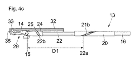
図3bには、連行体14の僅かに引き出された位置が示されており、連行体14は、引出し方向31における可動の家具部分3に対する手動による引張り運動によって、ばね装置16の力に抗して移動可能である。制御エレメント22は、最初に、第1のガイド軌道21の、引出し方向31に延びる真っ直ぐな第1の部分21aに沿って案内され、このとき固定箇所18は、連行体14と同じ速度で移動する。従って、連行体14に対して相対的な固定箇所18の間隔D(図4a,図4b)は、一時的に一定のままである。図3bに示した位置に続いて、第1のガイドエレメント22aは、第1のガイド軌道21の、螺旋形に形成された第2の部分21bと共働する。これによって、制御エレメント22は、引出し方向31に対して横方向の運動成分をもって案内され、これによって固定箇所18と連行体14との間の間隔D1(図4c)が増大し、その結果、固定箇所18の速度は、連行体14の速度に対して相対的に遅くなる。図3cには、連行体14の完全に引き出された位置が示されており、このとき第1のガイドエレメント22aは、第1のガイド軌道21の第2の部分21bの端部に位置している。
FIG. 3 b shows the position of the
図4a〜図4cには、引込み装置13が、引出し方向31における連行体14の異なった位置において側面図で示されている。引込み装置13はハウジング32を有しており、このハウジング32には、連行体14を案内するために、引出し方向31に延びる直線的な走行路34が配置されているかまたは形成されている。直線的な走行路34には、連行体14を離脱可能にロックするために、好ましくは円弧形または折り曲げられた屈曲部35が接続している。連行体14はガイド部分33を備えており、このガイド部分33によって、連行体14は、直線的な走行路34に沿って案内可能であり、かつ屈曲部35と離脱可能にロック可能である。図4aに示した連行体14の引き込まれた終端位置を起点として、連行体14は、可動の家具部分3に対する手動による引張り運動によって作動されて、引出し方向31に移動する。このとき制御エレメント22の第1のガイドエレメント22aは、第1のガイド軌道21の、引出し方向31に延びる真っ直ぐな第1の部分21aに沿って移動する。連行体14の軸15と第1のガイドエレメント22aとの間の間隔Dは、最初は一定のままである。連行体14の、図4bに示した引出し位置を起点として、第1のガイドエレメント22aは、第1のガイド軌道21の、螺旋形に形成された第2の部分21bに沿って移動し、これによってばね保持体17におけるばね装置16の固定箇所18が、引出し方向31に走行する連行体14の位置に対して後退し、これによって、間隔D1は、図4aおよび図4bに示した間隔Dに比べて増大する。連行体14のガイド部分33は、屈曲部35内に走入し、これによって連行体14は、軸15を中心にして旋回し、連行体14の切欠き29は、可動の家具部分3の連結エレメント36(図5a〜図5d)を解放する。連結されていない可動の家具部分3は、次いでさらに引出し方向31に移動可能である。図4cにおいて、連行体14は、引出し方向31とは逆向きの可動の家具部分3の引込み過程のための、セルフロック式にロックされた準備位置にある。可動の家具部分3の閉鎖時にこの可動の家具部分3は、再び連行体14の切欠き29と連結されるので、ガイド部分33は屈曲部35から外に移動し、かつ連行体14は、弛緩するばね装置16の力によって再び、図4aに示した引き込まれた終端位置に引き込まれる。
In FIGS. 4 a to 4 c, the retracting
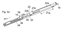
図5a〜図5dには、回転可能に支持された連行体14を備えた引込み装置13の別の実施形態が、異なった引込み位置において示されている。図面において、可動の家具部分3に固定することができる連結エレメント36が認識可能であり、この連結エレメント36は、連行体14と離脱可能に連結可能である。連行体14は、制御エレメント22の長手方向軸線23に対して同軸的に回転可能に支持されており、かつ引出し方向31に対して横方向に延びる傾斜面37を有している。この傾斜面37は、連結エレメント36との共働時に連行体14を、長手方向軸線23を中心にして回転させ、これによって制御エレメント22もまた同様に回転軸線23を中心にして一緒に回転し、かつ制御エレメント22の第1のガイドエレメント22aは、第1のガイド軌道21の第2の部分21bとのロック位置から離脱する。好ましくは、連行体14は制御エレメント22と一緒に一体に形成され、スライダ40に支持されており、このスライダ40は、スライダ40に配置されたピン39によって、ハウジング32のリニアガイド38に沿って移動可能に支持されている。直線的に走行可能なスライダ40には、第2のガイド軌道25が形成されており、この第2のガイド軌道25は、制御エレメント22の第2のガイドエレメント22bと共働する。
FIGS. 5a to 5d show another embodiment of the retracting
いまや可動の家具部分3が閉鎖されると(図3b)、連結エレメント36は、連行体14の傾斜面37と共働する。これによって連行体14は、長手方向軸線23を中心にして回転し、連結エレメント36と連結さる。このとき制御エレメント22の第1のガイドエレメント22aは、回転軸線23を中心にした制御エレメント22の回転によって、第1のガイド軌道21の第2の部分21bとのロックから離脱し、連結エレメント36と連結された連行体14は、制御エレメント22と一緒に、弛緩するばね装置16の力によって、閉鎖された終端位置の方向に引き込まれる(図5c)。いまや第1のガイドエレメント22aは、第1のガイド軌道21の、引出し方向31に延びる第1の部分21aと共働し、これによって連行体14は、制御エレメント22と一緒に、回転運動の実施なしに、長手方向軸線23に沿って閉鎖位置の方向に移動される。図5cにおいては、第1のガイド軌道21の第2の部分21bの端部も認識可能であり、この端部は、第1のガイドエレメント22aとの離脱可能なロックのために、回転軸線23に対して直角に延びる部分を有している。図5cに示した連行体14の位置を起点として、連行体14は、制御ピン22と一緒に、完全な終端位置に引込み可能である。いまや可動の家具部分3が再び開放されると、連行体14は、図5dを起点として、連結エレメント14によって再び引出し方向31において引っ張られる。このとき制御エレメント22は、この引出し運動の終了近くで、ガイド軌道21,25と共働するガイドエレメント22a,22bによって再び回転軸線23を中心にして回転し、これによって連行体14も同様に回転軸線23を中心にして回転し、かつ連結エレメント36は、さらなる引出し運動のために連行体14から解放される。
When the movable furniture part 3 is now closed (FIG. 3b), the connecting
Claims (14)
前記可動の家具部分(3)と離脱可能に連結可能な連行体(14)と、
前記連行体(14)の引出し方向(31)とは逆向きに前記連行体(14)に力を加える少なくとも1つのばね装置(16)であって、前記連行体(14)とは別体のばね保持体(17)を介して前記連行体(14)の前記引出し方向(31)において緊張可能であるばね装置(16)と、
前記連行体(14)と前記ばね保持体(17)との間において運動を連結する連結装置(30)であって、前記連行体(14)に対して相対的な、前記ばね保持体(17)における前記ばね装置(16)の固定箇所(18)の間隔(D)を、前記引出し方向(31)における前記連行体(14)の引出し時に変化させる連結装置(30)と、
を備える引込み装置(13)において、
前記連結装置(30)は、前記引出し方向(31)に延びる長手方向軸線(23)を有する少なくとも1つの制御エレメント(22)を有しており、該制御エレメント(22)は、前記引出し方向(31)における前記連行体(14)の引出し時に、前記固定箇所(18)と前記連行体(14)との間に存在する前記間隔(D)を変化させるために、少なくとも部分的に前記長手方向軸線(23)を中心にして回転する
ことを特徴とする、引込み装置。 A retracting device (13) for retracting the movably supported furniture part (3) relative to the furniture body (2) into a closed end position;
An entrainment body (14) removably connectable to the movable furniture part (3);
At least one spring device (16) that applies a force to the entrainment body (14) in a direction opposite to the pull-out direction (31) of the entrainment body (14), and is separate from the entrainment body (14); A spring device (16) that is tensionable in the pull-out direction (31) of the entrainment body (14) via a spring holder (17);
A coupling device (30) for coupling movement between the entraining body (14) and the spring holding body (17), wherein the spring holding body (17) is relative to the entraining body (14). A connecting device (30) that changes a distance (D) of the fixing portion (18) of the spring device (16) in the pulling direction (31) when the entrainment body (14) is pulled out;
In a retractor (13) comprising:
The coupling device (30) comprises at least one control element (22) having a longitudinal axis (23) extending in the withdrawal direction (31), the control element (22) being arranged in the withdrawal direction ( 31) when the entrainment body (14) is withdrawn in order to change the spacing (D) existing between the fixed part (18) and the entrainment body (14), at least partly in the longitudinal direction. Retraction device, characterized in that it rotates about an axis (23).
Applications Claiming Priority (3)
| Application Number | Priority Date | Filing Date | Title |
|---|---|---|---|
| ATA750/2015 | 2015-11-20 | ||
| ATA750/2015A AT517603B1 (en) | 2015-11-20 | 2015-11-20 | Feeding device for movable furniture parts |
| PCT/AT2016/060063 WO2017083894A1 (en) | 2015-11-20 | 2016-09-16 | Slide-in device for moveable furniture parts |
Publications (2)
| Publication Number | Publication Date |
|---|---|
| JP2018534081A JP2018534081A (en) | 2018-11-22 |
| JP6580265B2 true JP6580265B2 (en) | 2019-09-25 |
Family
ID=57003285
Family Applications (1)
| Application Number | Title | Priority Date | Filing Date |
|---|---|---|---|
| JP2018526243A Active JP6580265B2 (en) | 2015-11-20 | 2016-09-16 | Retraction device for movable furniture parts |
Country Status (9)
| Country | Link |
|---|---|
| US (1) | US10251481B2 (en) |
| EP (1) | EP3376899B1 (en) |
| JP (1) | JP6580265B2 (en) |
| CN (1) | CN108348069B (en) |
| AT (1) | AT517603B1 (en) |
| ES (1) | ES2728266T3 (en) |
| MY (1) | MY186912A (en) |
| TR (1) | TR201905722T4 (en) |
| WO (1) | WO2017083894A1 (en) |
Families Citing this family (6)
| Publication number | Priority date | Publication date | Assignee | Title |
|---|---|---|---|---|
| AT15246U1 (en) * | 2015-07-07 | 2017-04-15 | Blum Gmbh Julius | Drive device for a movable furniture part |
| AT517063B1 (en) * | 2015-07-07 | 2016-11-15 | Blum Gmbh Julius | Drive device for a movable furniture part |
| TWI616165B (en) * | 2017-03-07 | 2018-03-01 | 川湖科技股份有限公司 | Retracting mechanism for movable furniture parts |
| JP7155392B2 (en) * | 2018-04-02 | 2022-10-18 | サフラン キャビン インコーポレイティド | Damper for soft automatic opening and closing doors |
| CN110520589B (en) * | 2019-06-24 | 2021-04-16 | 佛山市爱迪尔卫浴有限公司 | Two-way damper and shower door assembly |
| DE102020106033A1 (en) * | 2020-03-05 | 2021-09-09 | Zim Flugsitz Gmbh | Leg rest of a passenger seat with a device |
Family Cites Families (22)
| Publication number | Priority date | Publication date | Assignee | Title |
|---|---|---|---|---|
| KR101056913B1 (en) * | 2007-02-21 | 2011-08-12 | 박윤식 | Automatic closing device attached to the bottom mounted slide |
| DE202008013230U1 (en) * | 2008-10-08 | 2010-02-25 | Paul Hettich Gmbh & Co. Kg | Opening device for a pull-out guide |
| DE102008051360A1 (en) * | 2008-10-15 | 2010-05-12 | Karl Simon Gmbh & Co. Kg | retraction device |
| DE102009012922A1 (en) * | 2009-03-12 | 2010-09-16 | Gronbach Forschungs- Und Entwicklungs Gmbh & Co. Kg | Device or furniture has body, drawer, which is pulled out from body, and move-in mechanism for moving-in drawer in body, where move-in mechanism has bolt, lever with guide for bolt and spring |
| US20110043087A1 (en) * | 2009-08-19 | 2011-02-24 | Hui-Chu Shih | Slide rail buffering structure |
| AT509064B1 (en) * | 2010-01-19 | 2011-06-15 | Blum Gmbh Julius | FEEDING DEVICE FOR DRAWERS |
| US8459758B2 (en) * | 2010-01-21 | 2013-06-11 | Actron Manufacturing, Inc. | Drawer slide auto-close dampening system with reset feature |
| JP5632645B2 (en) * | 2010-05-07 | 2014-11-26 | 株式会社ニフコ | Pull-in device and pull-in body used therefor |
| AT509923B1 (en) * | 2010-06-01 | 2013-12-15 | Blum Gmbh Julius | FEEDING DEVICE FOR PULLING A MOVABLE FURNITURE PART |
| DE102011051907A1 (en) * | 2011-07-18 | 2013-01-24 | Horst Lautenschläger | Retraction device for movable furniture components, particularly drawers, comprises movable carrier brought into releasable engagement with furniture component, where damping unit and spring unit stand in operative connection with carrier |
| GB2496864B (en) * | 2011-11-22 | 2016-08-31 | Titus Int Ltd | Improvements in damper assemblies |
| TWM440035U (en) * | 2011-12-13 | 2012-11-01 | Nan Juen Int Co Ltd | Improved automatic homing rail structure |
| TWM440036U (en) * | 2012-01-12 | 2012-11-01 | Nan Juen Int Co Ltd | Improved automatic homing rail buffer structure |
| DE102012100394A1 (en) * | 2012-01-18 | 2013-07-18 | Hettich-Heinze Gmbh & Co. Kg | retraction device |
| AT512513B1 (en) * | 2012-07-10 | 2013-09-15 | Blum Gmbh Julius | Drive device for a movable furniture part |
| KR101391247B1 (en) * | 2012-07-12 | 2014-05-02 | 박윤식 | Automatically closing apparatus |
| AT514141B1 (en) * | 2013-04-12 | 2015-08-15 | Blum Gmbh Julius | Drive device for a movable furniture part |
| AT514058B1 (en) * | 2013-04-12 | 2014-10-15 | Blum Gmbh Julius | Drive device for a movable furniture part |
| AT516159B1 (en) * | 2014-10-30 | 2016-03-15 | Blum Gmbh Julius | Feeding device for furniture parts |
| KR101626677B1 (en) * | 2014-11-18 | 2016-06-01 | 엘지전자 주식회사 | Rail assembly equipped with auto closing unit and Refrigerator having the same |
| AT516677B1 (en) * | 2015-01-02 | 2019-08-15 | Blum Gmbh Julius | furniture drive |
| TWI599332B (en) * | 2016-08-31 | 2017-09-21 | 川湖科技股份有限公司 | Retracting mechanism for a movable furniture part |
-
2015
- 2015-11-20 AT ATA750/2015A patent/AT517603B1/en not_active IP Right Cessation
-
2016
- 2016-09-16 EP EP16770873.4A patent/EP3376899B1/en active Active
- 2016-09-16 CN CN201680067425.1A patent/CN108348069B/en active Active
- 2016-09-16 MY MYPI2018000581A patent/MY186912A/en unknown
- 2016-09-16 JP JP2018526243A patent/JP6580265B2/en active Active
- 2016-09-16 ES ES16770873T patent/ES2728266T3/en active Active
- 2016-09-16 WO PCT/AT2016/060063 patent/WO2017083894A1/en active Application Filing
- 2016-09-16 TR TR2019/05722T patent/TR201905722T4/en unknown
-
2018
- 2018-05-02 US US15/969,323 patent/US10251481B2/en active Active
Also Published As
| Publication number | Publication date |
|---|---|
| JP2018534081A (en) | 2018-11-22 |
| CN108348069A (en) | 2018-07-31 |
| AT517603B1 (en) | 2017-03-15 |
| ES2728266T3 (en) | 2019-10-23 |
| TR201905722T4 (en) | 2019-05-21 |
| US20180249833A1 (en) | 2018-09-06 |
| CN108348069B (en) | 2019-09-13 |
| US10251481B2 (en) | 2019-04-09 |
| MY186912A (en) | 2021-08-26 |
| EP3376899A1 (en) | 2018-09-26 |
| WO2017083894A1 (en) | 2017-05-26 |
| EP3376899B1 (en) | 2019-02-27 |
| AT517603A4 (en) | 2017-03-15 |
Similar Documents
| Publication | Publication Date | Title |
|---|---|---|
| JP6580265B2 (en) | Retraction device for movable furniture parts | |
| KR101179095B1 (en) | Pull-in device | |
| JP6393429B2 (en) | Furniture drive | |
| JP6441475B2 (en) | Furniture parts pull back device | |
| JP5586847B2 (en) | Lockable extrusion equipment | |
| KR101179096B1 (en) | Pull-in device | |
| CN103080454B (en) | Pull-in device | |
| US10508483B2 (en) | Ejection device for a movable furniture part | |
| JP6367945B2 (en) | Drive unit for moving furniture parts | |
| JP5987827B2 (en) | Discharge device and drawer device | |
| JP2015208591A (en) | Slide rail and cabinet with drawer having the slide rail | |
| JP2016538941A5 (en) | ||
| CN112654758B (en) | Damping brake device for sliding panels and doors | |
| JP6491676B2 (en) | Furniture drive | |
| JP7254959B2 (en) | Drives for movable furniture parts | |
| RU2597818C2 (en) | Device for retraction of movable furniture part in middle position | |
| EP3933093B1 (en) | Detergent box assembly and washing device | |
| JP3861249B1 (en) | Flat door opening and closing mechanism | |
| EP3933094B1 (en) | Detergent box assembly and washing device |
Legal Events
| Date | Code | Title | Description |
|---|---|---|---|
| A621 | Written request for application examination |
Free format text: JAPANESE INTERMEDIATE CODE: A621 Effective date: 20180627 |
|
| TRDD | Decision of grant or rejection written | ||
| A01 | Written decision to grant a patent or to grant a registration (utility model) |
Free format text: JAPANESE INTERMEDIATE CODE: A01 Effective date: 20190729 |
|
| A61 | First payment of annual fees (during grant procedure) |
Free format text: JAPANESE INTERMEDIATE CODE: A61 Effective date: 20190827 |
|
| R150 | Certificate of patent or registration of utility model |
Ref document number: 6580265 Country of ref document: JP Free format text: JAPANESE INTERMEDIATE CODE: R150 |
|
| R250 | Receipt of annual fees |
Free format text: JAPANESE INTERMEDIATE CODE: R250 |
|
| R250 | Receipt of annual fees |
Free format text: JAPANESE INTERMEDIATE CODE: R250 |