JP6580080B2 - Light source driving apparatus and light source driving method - Google Patents
Light source driving apparatus and light source driving method Download PDFInfo
- Publication number
- JP6580080B2 JP6580080B2 JP2017015222A JP2017015222A JP6580080B2 JP 6580080 B2 JP6580080 B2 JP 6580080B2 JP 2017015222 A JP2017015222 A JP 2017015222A JP 2017015222 A JP2017015222 A JP 2017015222A JP 6580080 B2 JP6580080 B2 JP 6580080B2
- Authority
- JP
- Japan
- Prior art keywords
- dimming
- signal
- level
- light source
- instruction
- Prior art date
- Legal status (The legal status is an assumption and is not a legal conclusion. Google has not performed a legal analysis and makes no representation as to the accuracy of the status listed.)
- Active
Links
Images


Classifications
-
- Y—GENERAL TAGGING OF NEW TECHNOLOGICAL DEVELOPMENTS; GENERAL TAGGING OF CROSS-SECTIONAL TECHNOLOGIES SPANNING OVER SEVERAL SECTIONS OF THE IPC; TECHNICAL SUBJECTS COVERED BY FORMER USPC CROSS-REFERENCE ART COLLECTIONS [XRACs] AND DIGESTS
- Y02—TECHNOLOGIES OR APPLICATIONS FOR MITIGATION OR ADAPTATION AGAINST CLIMATE CHANGE
- Y02B—CLIMATE CHANGE MITIGATION TECHNOLOGIES RELATED TO BUILDINGS, e.g. HOUSING, HOUSE APPLIANCES OR RELATED END-USER APPLICATIONS
- Y02B20/00—Energy efficient lighting technologies, e.g. halogen lamps or gas discharge lamps
- Y02B20/40—Control techniques providing energy savings, e.g. smart controller or presence detection
Description
本発明は、光源駆動装置および光源駆動方法に関する。 The present invention relates to a light source driving device and a light source driving method.
光源駆動装置に対する調光指示信号の1つとして、PWM(Pulse Width Modulation)信号があり、そのデューティ比に応じて光源を調光する方法が知られている。一方、ヨーロッパを中心にDALI(Digital Addressable Lighting Interface、登録商標)と呼ばれる国際規格が、主に施設用照明制御として普及している。この他に、一般に0〜10Vの制御信号を調光指示信号として入力し、その電圧値に応じて調光する方法(アナログ調光、0−10V調光)も知られている。 As one of the dimming instruction signals for the light source driving device, there is a PWM (Pulse Width Modulation) signal, and a method of dimming the light source according to the duty ratio is known. On the other hand, an international standard called DALI (Digital Addressable Lighting Interface (registered trademark)) is mainly used as facility lighting control mainly in Europe. In addition, a method of inputting a control signal of 0 to 10 V as a dimming instruction signal and performing dimming according to the voltage value (analog dimming, 0-10 V dimming) is also known.
調光指示信号には指示レベル(調光指示レベル)が含まれているが、この指示レベルと光源の明るさ(光量、光源レベル)の関係は、一通りには決まっておらず、指示レベルと調光レベルの関係、及び、駆動回路によって決まる。指示レベルと調光レベルの関係の例として、指示レベルが一定量減少するときに調光レベルが一定比率で減少する関係(ログ調光カーブで示される関係)、指示レベルと調光レベルが比例する関係(リニア調光カーブで示される関係)などがある。 The dimming instruction signal includes an instruction level (dimming instruction level), but the relationship between the instruction level and the brightness of the light source (light quantity, light source level) is not fixed, and the instruction level And the dimming level and the driving circuit. As an example of the relationship between the indication level and the dimming level, the dimming level decreases at a constant rate when the indication level decreases by a certain amount (relationship indicated by the log dimming curve), and the indication level and the dimming level are proportional Relationship (relationship indicated by a linear dimming curve).
複数方式の調光指示信号と、指示レベルと光量の複数の関係とに対応するためには、それぞれの調光指示信号方式に対応し、さらに指示レベルと調光レベルの複数の対応関係(調光カーブ)、複数の駆動回路に対応できる調光制御の方法が必要となる。また、調光指示信号、調光カーブ、および、駆動回路を選択するための切替え手段を設ける必要がある。このために、部品点数が増加するとともに、光源駆動装置が大型化するという問題がある。 In order to correspond to a plurality of dimming instruction signals and a plurality of relations between the instruction level and the light quantity, it corresponds to each dimming instruction signal system, and further, a plurality of correspondence relations (indicating levels and dimming levels) A light control method capable of dealing with a plurality of drive circuits is required. In addition, it is necessary to provide switching means for selecting a dimming instruction signal, a dimming curve, and a drive circuit. For this reason, there is a problem that the number of parts increases and the light source driving device increases in size.
特許文献1に記載の技術は、1つの制御部(調光制御部)でPWMとDALIの調光指示信号に対応可能である。しかしながら、複数の調光カーブや複数の駆動回路に対応する方法は開示されていない。
本発明は、このような問題を解決することを目指したものであり、1つの制御部で複数方式の調光指示信号、複数の調光カーブ、複数の駆動回路に対応可能である光源駆動装置を提供することを目的とする。
The technique described in
The present invention aims to solve such a problem, and a light source driving device capable of supporting a plurality of dimming instruction signals, a plurality of dimming curves, and a plurality of driving circuits with one control unit. The purpose is to provide.
上記課題を解決するために本発明は、入力される調光指示信号に応じて光源を駆動する光源駆動装置であって、前記調光指示信号がPWM調光指示信号であるか、またはDALI調光指示信号であるかを判断して所定の範囲の調光指示レベルを生成する指示レベル生成部と、複数の調光カーブに含まれる所望の調光カーブに応じて前記調光指示レベルから調光レベルを生成する調光レベル生成部と、前記調光レベルから前記光源の駆動回路に依存した調光信号カーブに応じた調光信号を生成して、当該調光信号を前記光源の前記駆動回路に出力する調光信号生成部とを備えることを特徴とする光源駆動装置である。 The present invention for solving the above problems is a light source driver for driving the light source in response to the dimming instruction signal is inputted, whether the light control direction signal is a PWM dimming instruction signal, or DALI tone An instruction level generation unit that determines whether the signal is a light instruction signal and generates a dimming instruction level within a predetermined range, and adjusts from the dimming instruction level according to desired dimming curves included in a plurality of dimming curves. a dimming level generator for generating a light level, and generates a dimming signal corresponding to the dependent dimming signal curve driving circuit of the light source from the dimming level, the driving the dimming signal of the light source A light source driving device comprising a dimming signal generation unit for outputting to a circuit.
本発明によれば、1つの制御部で複数方式の調光指示信号、複数の調光カーブ、複数の駆動回路に対応可能である光源駆動装置を提供することができる。 ADVANTAGE OF THE INVENTION According to this invention, the light source drive device which can respond | correspond to the light control instruction | indication signal of a several system, a some light control curve, and a some drive circuit with one control part can be provided.
≪全体構成≫
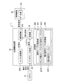
図1は、本実施形態に係る照明システム1の全体構成を例示する図である。照明システム1は、リモコン10と、光源駆動装置20と、照明装置30とを有する。照明装置30は、光源301を備える。
≪Overall structure≫
FIG. 1 is a diagram illustrating an overall configuration of a
リモコン10は、例えば壁面に取り付けられるダイヤル(不図示)付きのコントローラであり、ダイヤルが回された角度に応じた指示レベルを含む調光指示信号を光源駆動装置20に対して出力する。調光指示信号には、PWM方式とDALI方式とがある。PWM方式の指示レベルは、0〜65535の段階があり、DALI方式では0〜254の段階がある。いずれの方式でも指示レベル0は電源オフに対応する。
The
光源駆動装置20は、リモコン10から調光指示信号が入力され、調光指示信号に含まれる指示レベルに応じた直流電流を光源301に出力することで、指示レベルに応じた明るさになるように光源301を駆動する。光源駆動装置20は、インタフェース回路201と、制御部40と、記憶部202と、駆動回路203と、AC/DC変換部204とを備える。
The light
インタフェース回路201は、入力される調光指示信号をシリアル信号に変換して、制御部40に出力する。調光指示信号は、PWM調光指示信号またはDALI調光指示信号である。インタフェース回路201は、例えばアナログ回路で構成されて、広い電圧幅の差動信号である調光指示信号をマイコン(後述の制御部40)に対応したシリアル信号に変換し、電気的に絶縁する機能を有する。
The
制御部40は、例えばマイコンで構成され、インタフェース回路201から入力されるシリアル信号に応じた調光信号を駆動回路203に出力する。シリアル信号には、PWM調光指示信号またはDALI調光指示信号の指示レベルが含まれており、制御部40は、この指示レベルと、調光カーブと、駆動回路とに応じた調光信号を出力する。シリアル信号に含まれる指示レベルは、調光信号のデューティ比に反映される。制御部40の構成については、図2を参照して詳しく後述する。
The
記憶部202は、調光テーブル記憶域207と調光信号テーブル記憶域208とを備えるROM(Read Only Memory)、または、制御部40を構成するマイコンに含まれるROMであってもよいし、他の形態でもよい。
The
調光テーブル記憶域207は、調光カーブを近似するテーブル形式のデータの記憶領域であり、ログ調光カーブを近似するログ調光テーブル2071と、リニア調光カーブを近似するリニア調光テーブル2072とを格納している。なお、その他の調光カーブを用いるときには、当該調光カーブを近似するテーブルを備える。照明システム1の設置時に調光カーブを設定する場合、または、使用時に調光カーブを変更する場合には、これらの調光テーブルを変更する。調光カーブおよび調光テーブルについては、それぞれ図3と図4を参照して詳しく後述する。
The dimming
調光信号テーブル記憶域208は、調光レベルと調光信号のデューティ比との対応関係(調光信号カーブ)を近似するテーブル形式のデータの記憶領域であり、調光信号テーブル2081を備えている。調光信号カーブは、駆動回路203に依存しており、照明システム1を設置するときに駆動回路203に合わせて複数の調光信号テーブル2081から1つを選択する。または、駆動回路203に合わせて1つ存在する調光信号テーブル2081を書き換えてもよい。調光信号カーブおよび調光信号テーブルについては、それぞれ図5と図6を参照して詳しく後述する。
The dimming signal
駆動回路203は、光源301に対応した直流電流を電源として供給する装置である。制御部40から入力された調光信号のデューティ比に応じた直流電流が供給されることにより、光源301の明るさ(光量)が変化する。
AC/DC変換部204は、商用電源(不図示)からの交流電力を直流電力に変換して、駆動回路203に直流電力を供給する装置である。
The
The AC / DC conversion unit 204 is a device that converts AC power from a commercial power supply (not shown) into DC power and supplies the DC power to the
≪制御部の構成≫
図2は、本実施形態に係る光源駆動装置20が備える制御部40の構成を例示する機能ブロック図である。制御部40は、指示レベル生成部41と、調光レベル生成部42と、調光信号生成部43とを備える。
≪Configuration of control part≫
FIG. 2 is a functional block diagram illustrating the configuration of the
指示レベル生成部41は、インタフェース回路201から入力されたシリアル信号がPWM調光指示信号に基づく信号か、DALI調光指示信号に基づく信号かを判断する。さらに、指示レベル生成部41は、PWM調光指示信号またはDALI調光指示信号に含まれる指示レベルを取得して、調光レベル生成部42に出力する。指示レベル生成部41は、信号判断部411と、DALI検出部412と、PWM検出部413と、変換部414とを備える。
The instruction
信号判断部411は、シリアル信号がPWM調光指示信号に基づくか、DALI調光指示信号に基づくかを判断し、PWM調光情報をPWM検出部413に出力するか、または、DALI命令情報をDALI検出部412に出力する。DALI命令情報は、アドレス(例えば、リモコン10に複数の光源駆動装置20が接続された照明システム1における光源駆動装置20の識別番号やグループ番号)やコマンド、DALI調光情報を含む。
The
DALI検出部412は、入力されたDALI命令情報からDALI調光情報を取得し、その指示レベルを調光レベル生成部42に出力する。指示レベルは、0〜254の値である。
PWM検出部413は、入力されたPWM調光情報のデューティ比を計測し、デューティ比が0%のときはPWMレベルを0、デューティ比が100%のときはPWMレベルを65535として、変換部414に出力する。
変換部414は、入力されたPWMレベルを指示レベルに変換して、調光レベル生成部42に出力する。
The
The PWM detector 413 measures the duty ratio of the input PWM dimming information, and when the duty ratio is 0%, the PWM level is 0, and when the duty ratio is 100%, the PWM level is 65535, and the converter 414 Output to.
The conversion unit 414 converts the input PWM level into an instruction level and outputs it to the dimming
調光レベル生成部42は、指示レベルを調光レベルに変換する。調光レベルは0〜100の値である。変換には、リニア調光カーブに基づく変換とログ調光カーブに基づく変換があるが、他の調光カーブに基づいた変換でもよい。
The dimming
図3は、本実施形態に係る調光カーブを例示するグラフである。横軸は指示レベルであり、縦軸は調光レベルである。破線で示されるグラフは、リニア調光カーブ51であり、0〜254の指示レベルをリニアに0〜100の調光レベルに変換することを示している。実線で示されるグラフは、ログ調光カーブ52であり、0〜254の指示レベルを指数関数カーブに基づいて0〜100の調光レベルに変換することを示している。ログ調光カーブ52は、指示レベルをn、調光レベルをX(n)として式(1)に示される関数のグラフである。指示レベルがおおよそ25増えるごとに、調光レベルは倍になる。リニア調光カーブ51に比べてログ調光カーブ52は、人の目の反応度合いに近く、特に低いレベルの調光がしやすくなる。
FIG. 3 is a graph illustrating a dimming curve according to the present embodiment. The horizontal axis is the instruction level, and the vertical axis is the dimming level. A graph indicated by a broken line is a
![]()
![]()
図4は、本実施形態に係る光源駆動装置20が備える記憶部202に記憶される調光テーブルの構成を例示する図である。図4(a)は、ログ調光カーブ52に基づいて指示レベルを調光レベルに変換するときに使われるログ調光テーブル2071であり、指示レベルの列611と調光レベルの列612から構成される。各レコード(行)は、指示レベルに対応するログ調光カーブ52に基づく調光レベルを示す。図4(b)は、リニア調光カーブ51に基づいて指示レベルを調光レベルに変換するときに使われるリニア調光テーブル2072であり、指示レベルの列613と調光レベルの列614から構成される。各レコードは、指示レベルに対応するリニア調光カーブ51に基づく調光レベルを示す。
FIG. 4 is a diagram illustrating a configuration of a dimming table stored in the
図2の説明に戻り、調光信号生成部43は、入力された調光レベルに応じたデューティ比の調光信号を駆動回路203に出力する。調光レベルと調光信号のデューティ比の対応関係は、駆動回路203に依存しており、調光信号カーブで示すことができる。
Returning to the description of FIG. 2, the dimming
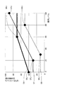
図5は、本実施形態に係る調光信号カーブを例示するグラフである。横軸は調光レベルであり、縦軸は調光信号のデューティ比(%)である。
機種Aの駆動回路に対応した太い実線で示される調光信号カーブ56は、調光レベルが0〜60の間では調光信号のデューティ比が40〜70%にリニアに変化し、調光レベルが60以上では調光信号のデューティ比は70%のままである。
FIG. 5 is a graph illustrating a dimming signal curve according to this embodiment. The horizontal axis represents the dimming level, and the vertical axis represents the duty ratio (%) of the dimming signal.
The
デューティ比の下限値は40%であり、この下限値となる調光レベルの最大値は0である。また、デューティ比の上限値は70%であり、この上限値となる調光レベルの最小値は60である。以下、この下限値と上限値に関して、下限点56Lが(0,40)、上限点56Uが(60,70)とも記す。
The lower limit value of the duty ratio is 40%, and the maximum value of the light control level that is the lower limit value is zero. The upper limit value of the duty ratio is 70%, and the minimum value of the light control level that is the upper limit value is 60. Hereinafter, regarding the lower limit value and the upper limit value, the
機種Bの駆動回路に対応した細い実線で示される調光信号カーブ57は、調光レベルが0〜20の間では調光信号のデューティ比は30%のままであり、調光レベルが20〜100の間では調光信号のデューティ比は30〜90%までリニアに変化する。下限点57Lは(20,30)、上限点57Uが(100,90)である。
In the
機種Cの駆動回路に対応した点線で示される調光信号カーブ58は、調光レベルが0〜30の間では調光信号のデューティ比は10%のまま、調光レベルが30〜80の間では調光信号のデューティ比は10〜50%までリニアに変化して、調光レベルが80以上では調光信号のデューティ比は50%のままである。下限点58Lは(30,10)、上限点58Uが(80,50)である。
The
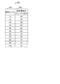
図6は、本実施形態に係る光源駆動装置20が備える記憶部202に記憶される調光信号テーブル2081の構成を例示する図である。調光信号テーブル2081は、調光信号カーブ56に基づいて調光レベルを調光信号に変換するときに使われるテーブル形式のデータであり、調光レベルの列631と調光信号のデューティ比の列632から構成される。各レコードは、調光レベルに対応する調光信号カーブ56に基づく調光信号でのデューティ比(%)を示す。
FIG. 6 is a diagram illustrating a configuration of the dimming signal table 2081 stored in the
≪調光制御処理≫
図7は、本実施形態に係る調光制御処理を示すフローチャートである。図7を参照しながら、光源駆動装置20の調光制御処理を説明する。
ステップS40において、インタフェース回路201が、リモコン10から入力された調光指示信号に応じたシリアル信号を生成して、制御部40の信号判断部411に出力する。
≪Dimming control processing≫
FIG. 7 is a flowchart showing the dimming control process according to the present embodiment. The dimming control processing of the light
In step S <b> 40, the
≪指示レベル生成ステップ≫
ステップS41において、信号判断部411は、入力されたシリアル信号がPWM調光指示信号に基づくか、DALI調光指示信号に基づくかを判断する。DALI調光指示信号には、リモコン10から光源駆動装置20に送信されるForwardフレームが含まれており、2つのForwardフレームの間には所定時間の休止期間がある。このForwardフレームに基づくシリアル信号や休止期間を解析することで、信号判断部411は、シリアル信号がPWM調光指示信号に基づくか、DALI調光指示信号に基づくかを判断する。
≪Instruction level generation step≫
In step S41, the
ステップS42において、信号判断部411は、シリアル信号がPWM調光指示信号に基づくと判断したときにはステップS43に進み、DALI調光指示信号に基づくと判断したときにはステップS46に進む。
ステップS43において、シリアル信号がPWM調光指示信号に基づくと判断した信号判断部411が、PWM調光情報をPWM検出部413に出力する。
In step S42, the
In step S43, the
ステップS44において、PWM検出部413は、入力されたPWM調光情報からPWMレベルを取得し、変換部414に出力する。
ステップS45において、変換部414は、PWMレベルを指示レベルに変換して、調光レベル生成部42に出力する。PWMレベルは0〜65535の値、指示レベルは0〜254の値であって、PWMレベルに254を乗じ、65535で除することで変換することができる。または、通常の除演算よりも処理負荷の軽い8ビット右シフト処理を利用して、指示レベルを算出してもよい。すなわち、8ビット右シフトして256で除した値を求め、この値が254を超えたときには254として、指示レベルを算出してもよい。
In step S <b> 44, the PWM detection unit 413 acquires the PWM level from the input PWM dimming information, and outputs the PWM level to the conversion unit 414.
In step S <b> 45, the conversion unit 414 converts the PWM level into an instruction level and outputs it to the dimming
ステップS46において、シリアル信号がDALI調光指示信号に基づくと判断した信号判断部411が、DALI命令情報をDALI検出部412に出力する。
ステップS47において、DALI検出部412は、入力されたDALI命令情報からDALI調光情報を取得し、その指示レベルを調光レベル生成部42に出力する。
In step S46, the
In step S <b> 47, the
≪調光レベル生成ステップ≫
ステップS48において、調光レベル生成部42が、調光テーブルを参照して入力された指示レベルを調光レベルに変換して、調光信号生成部43に出力する。調光テーブルがログ調光テーブル2071(図4(a)参照)である場合の変換方法を以下に説明する。
≪Dimming level generation step≫
In step S <b> 48, the dimming
調光レベル生成部42は、入力された指示レベルを指示レベルの列611にある値に切り上げて、切り上げた指示レベルに対応する調光レベルに変換する。例えば、指示レベルが107であれば、107以上の最小の値である125に切り上げて、調光レベルは3とする。
調光レベル生成部42は、ログ調光テーブル2071にある値で線形補間して指示レベルを調光レベルに変換もよい。例えば、指示レベルが180であれば、指示レベルが175と200の間で線形補間して調光レベルを14とする。リニア調光テーブル2072や別の調光テーブルを用いた場合でも、調光レベル生成部42は同様な方法で、指示レベルを調光レベルに変換できる。
The dimming
The dimming
≪調光信号生成ステップ≫
ステップS49において、調光信号生成部43が、調光信号テーブル2081(図6参照)を参照して入力された調光レベルに応じたデューティ比の調光信号を生成して、駆動回路203に出力する。調光レベルからデューティ比を算出する方法は、ステップS48と同様である。但し、調光レベルが0ならば、デューティ比は0%と算出する。
≪Dimming signal generation step≫
In step S49, the dimming
≪変形例≫
上記の実施形態では、調光信号生成部43は、調光信号テーブル2081を参照して調光レベルから調光信号のデューティ比を算出していた。調光信号生成部43が、調光信号テーブル2081の代わりに下限点と上限点からデューティ比を算出する方法を以下に説明する。
≪Modification≫
In the above embodiment, the dimming
図8は、本実施形態の変形例に係る光源駆動装置20が備える記憶部202に記憶される調光信号カーブの下限点と上限点のデータ構成を例示する図である。図8(a)は、調光信号カーブ56の下限点と上限点を示すデータである。下限点の調光レベル621、下限点の調光信号のデューティ比622、上限点の調光レベル623、上限点の調光信号のデューティ比624の順に並ぶ配列形式のデータである。
FIG. 8 is a diagram illustrating a data configuration of the lower limit point and the upper limit point of the dimming signal curve stored in the
入力された調光レベルが下限点の調光レベル621である0以下なら、調光信号生成部43は、下限点の調光信号のデューティ比622である40%と算出する。入力された調光レベルが上限点の調光レベル623である60以上なら、調光信号生成部43は、上限点の調光信号のデューティ比624である70%と算出する。入力された調光レベルが下限点の調光レベル621である0と上限点の調光レベル623である60との間なら、調光信号生成部43は、(0,40)と(60,70)を結ぶ線を用いて線形補間する。例えば、調光レベルが30なら、調光信号生成部43は、デューティ比を55%と算出する。但し、調光レベルが0ならば、デューティ比は0%と算出する。
If the input dimming level is 0 or less, which is the
図8(b)は、3つの調光信号カーブ(56〜58)の下限点と上限点を格納した表形式のデータである。駆動回路の機種641と、下限点の調光レベル642と、下限点の調光信号のデューティ比643と、上限点の調光レベル644と、上限点の調光信号のデューティ比645との5つの列からなる。各レコードが、調光信号カーブの下限点と上限点を示す。調光レベルから調光信号のデューティ比を算出する方法は、図8(a)と同様である。
FIG. 8B shows tabular data storing the lower and upper limit points of the three dimming signal curves (56 to 58). 5 of the
図8(a)で説明したように、調光信号テーブル2081の代わりに調光信号カーブの下限点と上限点を用いることで、記憶部202の容量を削減するという効果が得られる。また、図8(b)で説明したように、予め複数の調光信号カーブの下限点と上限点を記憶部202に格納しておくことで、駆動回路203ごとに記憶部202を書き換える手間を削減する効果が得られる。
As described with reference to FIG. 8A, by using the lower limit point and the upper limit point of the dimming signal curve instead of the dimming signal table 2081, an effect of reducing the capacity of the
図8では、調光信号カーブの下限点と上限点で線形補間することで、調光レベルから調光信号のデューティ比を算出する方法を示した。これは、調光信号カーブが、下限点より左と上限点の右では調光信号カーブが平坦であり、下限点と上限点の間ではほぼ直線であることを利用して、調光信号カーブを近似してデューティ比を算出する方法である。平坦ないしは直線の部分が少ない調光信号カーブに対して、調光レベルが小さい範囲では細かな区間で区切って、線形補間するようにしてもよい。 FIG. 8 shows a method for calculating the duty ratio of the dimming signal from the dimming level by performing linear interpolation at the lower limit and upper limit of the dimming signal curve. This is because the dimming signal curve is flat on the left of the lower limit point and on the right of the upper limit point, and is almost straight between the lower limit point and the upper limit point. Is used to calculate the duty ratio. A dimming signal curve with few flat or straight portions may be linearly interpolated by dividing the dimming signal curve into small sections in a range where the dimming level is small.
図9は、本実施形態の変形例に係る調光信号カーブの線形補間を説明するための図である。調光信号カーブ59は、機種Dの駆動回路に対応した調光信号カーブである。グラフ上の線形補間端点(59A〜59G)は、線形補間する直線(線分)の端点である。調光レベルが小さい範囲では、調光信号テーブル2081(図6参照)の調光レベルの列631は細かな区間で区切られ、細かく線形補間される。
人の目の反応度合いは暗いほど高いので、調光レベルが低い範囲では調光レベルを細かく区切り補間区間を細かくすることで、補間の誤差を小さくすることができ、記憶部の容量増大を抑えつつ暗い光の調光を容易にすることができる。
FIG. 9 is a diagram for explaining linear interpolation of a dimming signal curve according to a modification of the present embodiment. The
The darker the human eye is, the higher the degree of response, so in the low dimming level range, the dimming level is divided finely and the interpolation interval is made finer, so that the interpolation error can be reduced and the increase in the capacity of the storage unit is suppressed. In addition, it is possible to facilitate dimming of dark light.
ステップS48において調光レベル生成部42がリニア調光カーブ51を用いて指示レベルを調光レベルに変換するときには、リニア調光テーブル2072(図4(b)参照)を参照して変換していた。線形補間するために、指示レベルに100を乗じた後に254で除することによって変換してもよい。
When the dimming
≪効果≫
以上に説明したように、指示レベル生成部41が出力した指示レベルを、調光レベル生成部42が調光テーブルを参照して調光レベルに変換している。PWM調光指示信号とDALI調光指示信号のそれぞれから調光レベルを算出する場合に、それぞれの指示レベルと調光レベルの対応テーブルを記憶部202に格納して参照する方法に比べて、本発明では記憶部202の容量を削減することができる。
≪Effect≫
As described above, the dimming
また、照明システム1の利用者が複数の調光カーブを切り替えて調光する場合には、削減容量がさらに大きくなる。例えば、2種類の調光指示信号、3種類の調光カーブの場合に、従来技術では6つの指示レベルと調光レベルの対応テーブルが必要であった。しかし、本発明では3つの調光テーブルがあればよく、3つの調光テーブルに相当する記憶部202の容量を削減でき、記憶部202ないしは記憶部202を備えるマイコンのコストを削減できる。
利用者が調光カーブを切り替えないのであれば、1つの調光テーブルだけを備えればよく、記憶部202の容量が削減できる。
Further, when the user of the
If the user does not switch the dimming curve, it is sufficient to provide only one dimming table, and the capacity of the
調光テーブルを入れ替えることで、ログ調光カーブとリニア調光カーブ以外の調光カーブにも対応することができる。また、PWMとDALI以外の調光指示信号に対しても、指示レベル生成部41が当該調光指示信号に対応することで、調光テーブルを増やすことなく、当該調光指示信号の指示レベルを調光カーブに応じた調光レベルに変換することができる。
By changing the dimming table, it is possible to deal with dimming curves other than log dimming curves and linear dimming curves. In addition, for the dimming instruction signals other than PWM and DALI, the instruction
調光信号生成部43は、調光信号テーブル2081を参照して、指示レベルに対応するデューティ比の調光信号を駆動回路203に出力する。制御部40は、調光信号テーブル2081を変更することで、複数の駆動回路に対応することができ、開発・製造コストを削減することができる。また、例えば光源駆動装置を量産する場合、制御部40は調光信号テーブル2081を変更することで、部品の製品ばらつき(特性)による駆動回路203が出力する直流電流のばらつきを補正することができる。
The dimming
図8に示したように、調光信号テーブル2081の代わりに、調光信号カーブの下限点と上限点を参照することで、記憶部202の容量が削減でき、コストを削減できる。また、図9に示したように、調光信号カーブを線形補間するときに、調光レベルが小さい範囲では、細かな区間で区切って線形補間することで、人の目の反応度合いを考慮して誤差が小さくなるように調光信号のデューティ比を算出できる。
As shown in FIG. 8, the capacity of the
1 照明システム
10 リモコン
20 光源駆動装置
201 インタフェース回路
202 記憶部
203 駆動回路
204 AC/DC変換部
207 調光テーブル記憶域
2071 ログ調光テーブル
2072 リニア調光テーブル
208 調光信号テーブル記憶域
2081 調光信号テーブル
30 照明装置
301 光源
40 制御部
41 指示レベル生成部
411 信号判断部
412 DALI検出部
413 PWM検出部
414 変換部
42 調光レベル生成部
43 調光信号生成部
51 リニア調光カーブ
52 ログ調光カーブ
56、57、58、59 調光信号カーブ
56L、57L、58L 下限点
56U、57U、58U 上限点
DESCRIPTION OF
Claims (6)
前記調光指示信号がPWM調光指示信号であるか、またはDALI調光指示信号であるかを判断して所定の範囲の調光指示レベルを生成する指示レベル生成部と、
複数の調光カーブに含まれる所望の調光カーブに応じて前記調光指示レベルから調光レベルを生成する調光レベル生成部と、
前記調光レベルから前記光源の駆動回路に依存した調光信号カーブに応じた調光信号を生成して、当該調光信号を前記光源の前記駆動回路に出力する調光信号生成部と
を備えることを特徴とする光源駆動装置。 A light source driving device that drives a light source in response to an input dimming instruction signal,
An instruction-level generation unit for generating a dimming instruction level in a predetermined range to determine whether the light control direction signal or a PWM dimming instruction signal, or a DALI light control direction signal,
A dimming level generation unit that generates a dimming level from the dimming instruction level according to a desired dimming curve included in a plurality of dimming curves ;
And it generates a dimming signal corresponding to the dependent dimming signal curve to the drive circuit of the light source from the dimming level comprises the dimming signal and the dimming signal is output to the drive circuit generator of the light source A light source driving device characterized by that.
前記調光指示信号がPWM調光指示信号であるか、またはDALI調光指示信号であるかを判断して所定の範囲の調光指示レベルを生成する指示レベル生成ステップと、
複数の調光カーブに含まれる所望の調光カーブに応じて前記調光指示レベルから調光レベルを生成する調光レベル生成ステップと、
前記調光レベルから前記光源の駆動回路に依存した調光信号カーブに応じた調光信号を生成して、当該調光信号を前記光源の前記駆動回路に出力する調光信号生成ステップと
を備えることを特徴とする光源駆動方法。 A light source driving method for driving a light source according to an input dimming instruction signal,
An instruction level generation step of generating a dimming instruction level in a predetermined range to determine whether the light control direction signal or a PWM dimming instruction signal, or a DALI light control direction signal,
A dimming level generation step of generating a dimming level from the dimming instruction level according to a desired dimming curve included in a plurality of dimming curves ;
And it generates a dimming signal corresponding to the dependent dimming signal curve to the drive circuit of the light source from the dimming level comprises the dimming signal and the driving circuit dimming signal generating step of outputting to the light source And a light source driving method.
Priority Applications (1)
| Application Number | Priority Date | Filing Date | Title |
|---|---|---|---|
| JP2017015222A JP6580080B2 (en) | 2017-01-31 | 2017-01-31 | Light source driving apparatus and light source driving method |
Applications Claiming Priority (1)
| Application Number | Priority Date | Filing Date | Title |
|---|---|---|---|
| JP2017015222A JP6580080B2 (en) | 2017-01-31 | 2017-01-31 | Light source driving apparatus and light source driving method |
Publications (2)
| Publication Number | Publication Date |
|---|---|
| JP2018125119A JP2018125119A (en) | 2018-08-09 |
| JP6580080B2 true JP6580080B2 (en) | 2019-09-25 |
Family
ID=63109707
Family Applications (1)
| Application Number | Title | Priority Date | Filing Date |
|---|---|---|---|
| JP2017015222A Active JP6580080B2 (en) | 2017-01-31 | 2017-01-31 | Light source driving apparatus and light source driving method |
Country Status (1)
| Country | Link |
|---|---|
| JP (1) | JP6580080B2 (en) |
Families Citing this family (2)
| Publication number | Priority date | Publication date | Assignee | Title |
|---|---|---|---|---|
| CN111511077B (en) * | 2019-01-31 | 2022-07-08 | 松下知识产权经营株式会社 | Dimming curve generation method, dimming curve generation device and LED lighting device |
| WO2024059111A1 (en) * | 2022-09-13 | 2024-03-21 | Rensselaer Polytechnic Institute | Temporal light artifact-free dimming control for lighting sources |
-
2017
- 2017-01-31 JP JP2017015222A patent/JP6580080B2/en active Active
Also Published As
| Publication number | Publication date |
|---|---|
| JP2018125119A (en) | 2018-08-09 |
Similar Documents
| Publication | Publication Date | Title |
|---|---|---|
| CN101751866B (en) | Backlight brightness control for panel display device | |
| JP4295567B2 (en) | Display response speed increasing device | |
| JP6580080B2 (en) | Light source driving apparatus and light source driving method | |
| KR101473808B1 (en) | Display device and driving method of the same | |
| CN103854599A (en) | Method and apparatus for controlling current of organic light emitting diode display device | |
| CN1929624B (en) | Gamma curve generation method and device for the same | |
| WO2016136852A1 (en) | Signal generation circuit, voltage converter, and signal generation method | |
| EP2333764A1 (en) | Image display device | |
| KR100245921B1 (en) | Analog interface liquid crystal display apparatus and analog interface display apparatus | |
| CN103477385B (en) | Display device, display packing | |
| JP4010983B2 (en) | Plasma display panel address data automatic power control method and apparatus, and plasma display panel apparatus having the apparatus | |
| KR20170099422A (en) | Boost convertor, display device including the same, and method of controlling power | |
| KR20060123380A (en) | Apparatus and method for producing variable intensity of light | |
| US9318061B2 (en) | Method and device for mapping input grayscales into output luminance | |
| KR20120090635A (en) | Gamma control mapping circuit and method, and organic emmiting display device | |
| JP2007272144A (en) | Gamma correction and display device | |
| JP2005521904A (en) | Window brightness enhancement for LCD | |
| JP4010510B2 (en) | Plasma display panel address data automatic power control method, apparatus thereof, and plasma display panel having the apparatus | |
| JP2020169871A (en) | Battery residual value display device | |
| JP2017033841A (en) | Light source drive device and dimming and toning control method | |
| CN105448240A (en) | Display driving device, display device, and display data correction method | |
| JP5477804B2 (en) | Backlight device and backlight drive device | |
| CN106899799B (en) | Optical image stabilization actuator driver power distribution control | |
| TW543281B (en) | Predictive control of a generator output | |
| JP5619101B2 (en) | Lighting device and display device |
Legal Events
| Date | Code | Title | Description |
|---|---|---|---|
| A621 | Written request for application examination |
Free format text: JAPANESE INTERMEDIATE CODE: A621 Effective date: 20180709 |
|
| A977 | Report on retrieval |
Free format text: JAPANESE INTERMEDIATE CODE: A971007 Effective date: 20190412 |
|
| A131 | Notification of reasons for refusal |
Free format text: JAPANESE INTERMEDIATE CODE: A131 Effective date: 20190423 |
|
| A521 | Written amendment |
Free format text: JAPANESE INTERMEDIATE CODE: A523 Effective date: 20190610 |
|
| TRDD | Decision of grant or rejection written | ||
| A01 | Written decision to grant a patent or to grant a registration (utility model) |
Free format text: JAPANESE INTERMEDIATE CODE: A01 Effective date: 20190806 |
|
| A61 | First payment of annual fees (during grant procedure) |
Free format text: JAPANESE INTERMEDIATE CODE: A61 Effective date: 20190827 |
|
| R150 | Certificate of patent or registration of utility model |
Ref document number: 6580080 Country of ref document: JP Free format text: JAPANESE INTERMEDIATE CODE: R150 |