JP6577880B2 - Image forming apparatus - Google Patents
Image forming apparatus Download PDFInfo
- Publication number
- JP6577880B2 JP6577880B2 JP2016020834A JP2016020834A JP6577880B2 JP 6577880 B2 JP6577880 B2 JP 6577880B2 JP 2016020834 A JP2016020834 A JP 2016020834A JP 2016020834 A JP2016020834 A JP 2016020834A JP 6577880 B2 JP6577880 B2 JP 6577880B2
- Authority
- JP
- Japan
- Prior art keywords
- label
- image
- interval
- image forming
- unit
- Prior art date
- Legal status (The legal status is an assumption and is not a legal conclusion. Google has not performed a legal analysis and makes no representation as to the accuracy of the status listed.)
- Active
Links
Images


Classifications
-
- G—PHYSICS
- G03—PHOTOGRAPHY; CINEMATOGRAPHY; ANALOGOUS TECHNIQUES USING WAVES OTHER THAN OPTICAL WAVES; ELECTROGRAPHY; HOLOGRAPHY
- G03G—ELECTROGRAPHY; ELECTROPHOTOGRAPHY; MAGNETOGRAPHY
- G03G15/00—Apparatus for electrographic processes using a charge pattern
- G03G15/14—Apparatus for electrographic processes using a charge pattern for transferring a pattern to a second base
- G03G15/16—Apparatus for electrographic processes using a charge pattern for transferring a pattern to a second base of a toner pattern, e.g. a powder pattern, e.g. magnetic transfer
- G03G15/1605—Apparatus for electrographic processes using a charge pattern for transferring a pattern to a second base of a toner pattern, e.g. a powder pattern, e.g. magnetic transfer using at least one intermediate support
-
- G—PHYSICS
- G03—PHOTOGRAPHY; CINEMATOGRAPHY; ANALOGOUS TECHNIQUES USING WAVES OTHER THAN OPTICAL WAVES; ELECTROGRAPHY; HOLOGRAPHY
- G03G—ELECTROGRAPHY; ELECTROPHOTOGRAPHY; MAGNETOGRAPHY
- G03G15/00—Apparatus for electrographic processes using a charge pattern
- G03G15/65—Apparatus which relate to the handling of copy material
- G03G15/6517—Apparatus for continuous web copy material of plain paper, e.g. supply rolls; Roll holders therefor
- G03G15/652—Feeding a copy material originating from a continuous web roll
-
- G—PHYSICS
- G03—PHOTOGRAPHY; CINEMATOGRAPHY; ANALOGOUS TECHNIQUES USING WAVES OTHER THAN OPTICAL WAVES; ELECTROGRAPHY; HOLOGRAPHY
- G03G—ELECTROGRAPHY; ELECTROPHOTOGRAPHY; MAGNETOGRAPHY
- G03G21/00—Arrangements not provided for by groups G03G13/00 - G03G19/00, e.g. cleaning, elimination of residual charge
- G03G21/14—Electronic sequencing control
-
- G—PHYSICS
- G03—PHOTOGRAPHY; CINEMATOGRAPHY; ANALOGOUS TECHNIQUES USING WAVES OTHER THAN OPTICAL WAVES; ELECTROGRAPHY; HOLOGRAPHY
- G03G—ELECTROGRAPHY; ELECTROPHOTOGRAPHY; MAGNETOGRAPHY
- G03G2215/00—Apparatus for electrophotographic processes
- G03G2215/00172—Apparatus for electrophotographic processes relative to the original handling
- G03G2215/00206—Original medium
- G03G2215/00219—Paper
- G03G2215/00232—Non-standard format
- G03G2215/0024—Small sized, e.g. postcards
-
- G—PHYSICS
- G03—PHOTOGRAPHY; CINEMATOGRAPHY; ANALOGOUS TECHNIQUES USING WAVES OTHER THAN OPTICAL WAVES; ELECTROGRAPHY; HOLOGRAPHY
- G03G—ELECTROGRAPHY; ELECTROPHOTOGRAPHY; MAGNETOGRAPHY
- G03G2215/00—Apparatus for electrophotographic processes
- G03G2215/00362—Apparatus for electrophotographic processes relating to the copy medium handling
- G03G2215/00443—Copy medium
- G03G2215/00451—Paper
- G03G2215/00455—Continuous web, i.e. roll
-
- G—PHYSICS
- G03—PHOTOGRAPHY; CINEMATOGRAPHY; ANALOGOUS TECHNIQUES USING WAVES OTHER THAN OPTICAL WAVES; ELECTROGRAPHY; HOLOGRAPHY
- G03G—ELECTROGRAPHY; ELECTROPHOTOGRAPHY; MAGNETOGRAPHY
- G03G2215/00—Apparatus for electrophotographic processes
- G03G2215/00362—Apparatus for electrophotographic processes relating to the copy medium handling
- G03G2215/00535—Stable handling of copy medium
- G03G2215/00556—Control of copy medium feeding
- G03G2215/00599—Timing, synchronisation
-
- G—PHYSICS
- G03—PHOTOGRAPHY; CINEMATOGRAPHY; ANALOGOUS TECHNIQUES USING WAVES OTHER THAN OPTICAL WAVES; ELECTROGRAPHY; HOLOGRAPHY
- G03G—ELECTROGRAPHY; ELECTROPHOTOGRAPHY; MAGNETOGRAPHY
- G03G2215/00—Apparatus for electrophotographic processes
- G03G2215/01—Apparatus for electrophotographic processes for producing multicoloured copies
- G03G2215/0103—Plural electrographic recording members
- G03G2215/0119—Linear arrangement adjacent plural transfer points
- G03G2215/0122—Linear arrangement adjacent plural transfer points primary transfer to an intermediate transfer belt
- G03G2215/0125—Linear arrangement adjacent plural transfer points primary transfer to an intermediate transfer belt the linear arrangement being horizontal or slanted
- G03G2215/0129—Linear arrangement adjacent plural transfer points primary transfer to an intermediate transfer belt the linear arrangement being horizontal or slanted horizontal medium transport path at the secondary transfer
Description
本発明は、中間転写方式を採用した電子写真方式の画像形成装置であって、連続した媒体に画像を形成する画像形成装置に関する。 The present invention relates to an electrophotographic image forming apparatus that employs an intermediate transfer system, and relates to an image forming apparatus that forms an image on a continuous medium.
従来の画像形成装置は、トナー画像を生成する画像形成ユニットが中間転写ベルト上にトナー画像を1次転写し、そのトナー画像を記録媒体に2次転写する際、中間転写ベルト上のトナー画像の形成位置と記録媒体の位置を検知して記録媒体の搬送速度を加速させてトナー画像を記録媒体の正しい位置に形成するようにしている(例えば、特許文献1参照)。 In a conventional image forming apparatus, when an image forming unit that generates a toner image primarily transfers a toner image onto an intermediate transfer belt and secondarily transfers the toner image onto a recording medium, the toner image on the intermediate transfer belt is transferred. By detecting the formation position and the position of the recording medium, the conveyance speed of the recording medium is accelerated to form a toner image at the correct position of the recording medium (see, for example, Patent Document 1).
しかしながら、従来の技術においては、ラベルロール紙やプレ印刷連続紙等の連続紙にトナー画像を形成する場合、連続紙上のトナー画像を形成するべき位置と、実際にトナー画像が形成される位置とがずれてしまうという問題がある。
本発明は、このような問題を解決することを課題とし、連続紙上のトナー画像を形成するべき位置と、実際にトナー画像が形成される位置とのずれを抑制することを目的とする。
However, in the conventional technology, when a toner image is formed on a continuous paper such as a label roll paper or a pre-printed continuous paper, the position on which the toner image is to be formed on the continuous paper, and the position where the toner image is actually formed. There is a problem that shifts.
An object of the present invention is to solve such a problem, and an object thereof is to suppress a shift between a position where a toner image is to be formed on continuous paper and a position where a toner image is actually formed.
そのため、本発明は、帯電された像担持体に静電潜像を形成する露光部と、前記像担持体に形成された静電潜像に現像剤を供給することにより現像剤像を形成する現像部と、前記像担持体に形成された現像剤像を中間転写体に転写する1次転写部と、台紙上に間隔をおいて設けられた複数のラベルを備える連続媒体を搬送する搬送部と、搬送される連続媒体に中間転写体に形成された現像剤像を転写する2次転写部と、連続媒体の搬送方向における前記2次転写部の上流に配置され、通過する連続媒体のラベルにおける前記現像剤像を転写する位置の間隔を検知する間隔検知部と、前記間隔検知部が検知した前記間隔を間隔情報として記憶する間隔情報記憶部と、前記間隔情報記憶部に記憶された間隔情報に基づいて前記像担持体に静電潜像を形成するタイミングを制御するとともに、前記間隔検知部で検知した前記間隔に基づいて前記間隔情報記憶部の間隔情報を更新する制御部と、を有し、前記間隔情報記憶部は、画像形成条件に対応させて前記間隔情報を記憶する領域を有し、前記制御部は、前記連続媒体を給紙する前に、前記間隔情報記憶部に記憶された間隔情報を前記画像形成条件毎の基準値で初期化し、前記間隔検知部で検知した前記間隔であって前記間隔検知部を順次通過したラベルの前記間隔の平均値に基づいて前記画像形成条件に対応する前記間隔情報記憶部の間隔情報を更新し、前記間隔検知部で間隔が検知されたラベルの後に順次搬送されて前記2次転写部に到達するそれぞれのラベルに対し、更新された前記間隔情報に基づいて、現像剤像を転写する位置に合わせるように、前記露光部による前記像担持体に形成する静電潜像の形成タイミングを制御することを特徴とする。
For this reason, the present invention forms a developer image by supplying an exposure unit for forming an electrostatic latent image on a charged image carrier and supplying the developer to the electrostatic latent image formed on the image carrier. A developing unit, a primary transfer unit that transfers the developer image formed on the image carrier to an intermediate transfer member, and a conveyance unit that conveys a continuous medium having a plurality of labels provided on the mount at intervals. A secondary transfer portion that transfers the developer image formed on the intermediate transfer member onto the conveyed continuous medium, and a label of the continuous medium that is disposed upstream of the secondary transfer portion in the conveying direction of the continuous medium. An interval detection unit that detects an interval between positions where the developer image is transferred, an interval information storage unit that stores the interval detected by the interval detection unit as interval information, and an interval stored in the interval information storage unit An electrostatic latent image on the image carrier based on information It controls the timing of formation, and a control unit for updating interval information of the distance information storage unit based on the distance detected by the distance detecting unit, the distance information storage unit, the image forming conditions The control unit has a region for storing the interval information correspondingly, and the control unit sets the interval information stored in the interval information storage unit as a reference value for each image forming condition before feeding the continuous medium. initializing, updating interval information of the distance information storage unit corresponding to the image forming conditions based on the average value of the interval of labels sequentially passes through the interval detection unit an the distance detected by the distance detecting unit And a position at which the developer image is transferred to each label that is sequentially conveyed after the label whose interval is detected by the interval detection unit and reaches the secondary transfer unit based on the updated interval information. Fit manner, and controls the timing of forming an electrostatic latent image formed on the image carrier by the exposure unit.
このようにした本発明は、連続紙上のトナー画像を形成するべき位置と、実際にトナー画像が形成される位置とのずれを抑制することができるという効果が得られる。 According to the present invention as described above, it is possible to suppress the deviation between the position where the toner image is to be formed on the continuous paper and the position where the toner image is actually formed.
以下、図面を参照して本発明による画像形成装置の実施例を説明する。 Embodiments of an image forming apparatus according to the present invention will be described below with reference to the drawings.
図1は実施例における画像形成装置の構成を示す概略側断面図である。
図1において、画像形成装置1は、例えば中間転写方式を採用した電子写真方式のプリンタであり、連続した媒体(以下、「連続媒体」という。)に画像を形成するものである。本実施例では、連続媒体をラベルロール紙として説明する。
FIG. 1 is a schematic cross-sectional side view showing the configuration of the image forming apparatus in the embodiment.
In FIG. 1, an
画像形成装置1は、4つの独立した画像形成ユニット2Y、2M、2C、2Kが中間転写ベルト12の表面に接触し、図中矢印Aが示す回転方向における上流から画像形成ユニット2Y、画像形成ユニット2M、画像形成ユニット2C、画像形成ユニット2Kの順に配設されている。画像形成ユニット2Y、2M、2C、2Kは、それぞれY(イエロー)、M(マゼンタ)、C(シアン)、K(ブラック)の各色の現像剤としてのトナーを備え、中間転写ベルト12の表面に現像剤像としてのトナー画像を形成する。
In the
ここで、画像形成手段としての画像形成ユニット2Y、2M、2C、2Kの構成を、画像形成ユニット2Kを例とし、図2の画像形成ユニットの構成を示す概略側断面図に基づいて説明する。
図2において、画像形成ユニット2Kは、感光体6K、感光体6Kの表面を一様に帯電させるチャージローラ5K、感光体6Kの表面を露光して静電潜像を書き込むLED(Light Emitting Diode)ヘッド3K、感光体6K表面に形成された静電潜像をトナーで現像する現像ローラ7K、現像ローラ7Kの表面にトナーを供給しつつ現像ローラ7Kとの間でトナーをこすりつけてマイナス極性に摩擦帯電させるスポンジローラ9K、スポンジローラ9Kにトナーを供給するトナータンク10K、感光体6Kの表面に残留したトナーを除去するクリーニングブレード4Kを有している。トナータンク10Kには、ブラックトナーが収容されている。
画像形成ユニット2Y、2M、2Cは、画像形成ユニット2Kと同様の構成を有し、トナータンクに収容されるトナーが、それぞれイエロートナー、マゼンタトナー、シアントナーとなる。
Here, the configuration of the
In FIG. 2, an
The
図1の説明に戻る。
中間転写体としての中間転写ベルト12は、駆動ローラ13、アイドルローラ14、2次転写バックアップローラ17、およびテンションローラ18に張架され、駆動源としてのモータによって図中矢印Aが示す方向に回転駆動される。また、中間転写ベルト12を挟んで感光体6Y、6M、6C、6Kと対向する位置に、1次転写ローラ15Y、15M、15C、15Kがそれぞれ配設されている。
Returning to the description of FIG.
An
1次転写ローラ15Y、15M、15C、15Kは、付勢手段としてのスプリングにより感光体6Y、6M、6C、6Kに押圧されており、感光体6Y、6M、6C、6Kとの間に1次転写部(1次転写ニップ部)を形成している。
1次転写部において、感光体6Y、6M、6C、6K上に形成されたトナー画像の中間転写ベルト12上への転写が行われる。中間転写ベルト12は、転写されたトナー画像を表面に保持して2次転写部へ搬送する。
The
In the primary transfer portion, the toner images formed on the
画像形成装置1は、連続した媒体として巻き回された未印刷のラベルロール紙20aを備え、ラベルロール紙20aから引き出されたラベル紙20bに画像が形成され、そのラベル紙20bがリワインダー21に巻き取られ、画像形成済みのラベルロール紙20cとして巻き取られるようになっている。
The
ラベルロール紙20aから引き出されたラベル紙20bは、給紙ローラ28とピンチローラ27とにより挟持されて図中矢印Bが示す搬送方向に搬送され、ガイド41に案内されて透過型カット位置検知センサ22、および反射型カット位置検知センサ25が配置された位置を通過する。
透過型カット位置検知センサ22は、ラベル紙20bを挟むように配置された発光部23と受光部24とから構成される透過型光学センサであり、ラベル紙20bのおもて面に設けられた各ラベルの先端を検知するものである。
The
The transmissive cut
反射型カット位置検知センサ25は、発光部でラベル紙20bに照射した反射光を受光部で受光する反射型光学センサであり、ラベル紙20bの裏面に設けられたブラックマークを検知するものである。
ここで、透過型カット位置検知センサ22が検知するラベル紙20bを図6に基づいて説明する。図6(a)はラベル紙20bのおもて面の平面図、図6(b)はラベル紙20bの側面図、図6(c)はラベル紙20bの側面の拡大図である。
The reflection-type cut
Here, the
図6において、ラベル紙20bは、連続した台紙47に、所定の間隔を保持して複数のラベル46が貼付されている。なお、ラベル46間には、台紙47のみが存在し、ラベルカスは存在しない。
ラベル紙20bは、図6(b)(c)に示す台紙47およびラベル46が存在する部分と、台紙47のみが存在する部分とでは、台紙47のみが存在する部分の方が、台紙47およびラベル46が存在する部分より、光の透過率が高い。
In FIG. 6, the
6B and 6C, the portion where the
そのため、図7(b)に示すように、透過型カット位置検知センサ22は、図中矢印Bが示す搬送方向に搬送されるラベル紙20bが通過するとき、図7(c)に示すように、出力電圧を出力する。制御部は、その出力電圧の変化に基づいて、それぞれのラベル46の先端の位置を検出し、ラベル46が台紙47に貼付されている間隔であるラベルピッチLPを検出することができる。なお、図7(a)はラベル紙20bのおもて面の平面図、図7(b)はラベル紙20bおよび透過型カット位置検知センサ22の側面図、図7(c)は透過型カット位置検知センサ22の出力電圧の波形図である。
Therefore, as shown in FIG. 7B, when the
また、反射型カット位置検知センサ25が検知するラベル紙20bを図8に基づいて説明する。図8(a)はラベル紙20bのおもて面の平面図、図8(b)はラベル紙20bの側面図、図8(c)はラベル紙20bの側面の拡大図である。
図8において、ラベル紙20bは、連続した台紙47のおもて面の全面に、複数のラベル46が連続して貼付されている。それぞれのラベル46は、ラベルカス48を挟み、切込み46aによって切り分けられている。
The
In FIG. 8, the
ラベル紙20bは、図8(b)(c)に示すように、台紙47の裏面にはラベル46の切込み46aに合わせてラベル46の先端部にブラックマーク49が印刷されている。
ラベル紙20bは、図8(b)(c)に示すように、ブラックマーク49が印刷されている部分と、ブラックマーク49が印刷されていない部分とでは、ブラックマーク49が印刷されている部分の方が、ブラックマーク49が印刷されていない部分より、光の反射率が低い。
As shown in FIGS. 8B and 8C, the
As shown in FIGS. 8B and 8C, the
そのため、反射型カット位置検知センサ25は、図9(b)に示すように、図中矢印Bが示す搬送方向に搬送されるラベル紙20bが通過するとき、図9(c)に示すように、出力電圧を出力する。制御部は、その出力電圧の変化に基づいて、それぞれのラベル46の先端の位置を検出し、ラベル46が台紙47に貼付されている間隔であるラベルピッチLPを検出することができる。なお、図9(a)はラベル紙20bのおもて面の平面図、図9(b)はラベル紙20bおよび反射型カット位置検知センサ25の側面図、図9(c)は反射型カット位置検知センサ25の出力電圧の波形図である。
Therefore, as shown in FIG. 9B, the reflective cut
このように、透過型カット位置検知センサ22、および反射型カット位置検知センサ25は、台紙47に貼付されているラベル46の搬送方向における先頭間の距離であるラベルピッチLPを検出する。
なお、ラベル紙20bは、台紙47の裏面にはラベル46の切込み46aに合わせてラベル46の先端部にブラックマーク49が印刷されているものとして説明するが、ラベルピッチLPと同じ間隔を保持していれば、ブラックマーク49がラベル46の先端部からずれて印刷されていても良い。
As described above, the transmission-type cut
The
図1の説明に戻り、ラベル紙20bは、さらにガイド41に案内されてカッター26に到達し、カッター26で所定の長さに切断される。
ラベル紙20bは、さらにガイド41に案内されて第1中間搬送ローラ30と、第1中間搬送ローラ30に対向する第1ピンチローラ29との接触部(以下、「ニップ部」という。)で挟持され、第1中間搬送ローラ30の回転駆動により搬送される。さらに、ラベル紙20bは、ガイド41に案内されて第2中間搬送ローラ32と、第2中間搬送ローラ32に対向する第2ピンチローラ31とのニップ部で挟持され、第2中間搬送ローラ32の回転駆動により搬送される。
Returning to the description of FIG. 1, the
The
ラベル紙20bは、さらにガイド41に案内されて透過型書出し位置検知センサ33および反射型書出し位置検知センサ36が配置された位置を通過する。
間隔検知手段としての透過型書出し位置検知センサ33および反射型書出し位置検知センサ36は、図中矢印Bが示すラベル紙20bの搬送方向における2次転写ローラ16および2次転写バックアップローラ17の上流に配置され、ラベル紙20bにおけるトナー画像を転写する位置の間隔を検知するものである。
The
The transmission type writing
透過型書出し位置検知センサ33は、透過型カット位置検知センサ22と同様の構成であり、ラベル紙20bは挟むように配置された発光部34と受光部35とから構成される透過型光学センサであり、ラベル紙20bのおもて面に設けられた各ラベルの先端を検知し、トナー画像を転写する位置の間隔であるラベルの間隔(図7に示すラベルピッチLP)を検知するものである。
The transmission type writing
反射型書出し位置検知センサ36は、反射型カット位置検知センサ25と同様の構成であり、発光部でラベル紙20bに照射した反射光を受光部で受光する反射型光学センサであり、ラベル紙20bの裏面に設けられたブラックマークを検知し、トナー画像を転写する位置の間隔であるラベルの間隔(図9に示すラベルピッチLP)を検知するものである。
The reflection-type writing
このように、透過型書出し位置検知センサ33および反射型書出し位置検知センサ36は、透過型カット位置検知センサ22および反射型カット位置検知センサ25と同様に、台紙47に貼付されているラベル46の搬送方向における先頭間の距離であるラベルピッチLPを検出する。
ラベル紙20bは、さらにガイド41に案内されて2次転写ローラ16と2次転写バックアップローラ17とにより形成される2次転写部(2次転写ニップ部)に搬送される。
As described above, the transmission type writing
The
転写手段としての2次転写ローラ16と2次転写バックアップローラ17は、搬送されるラベル紙20bにトナー画像を転写するものである。ラベル紙20bにトナー画像が転写されるときは、各ラベルと中間転写ベルト12上に1次転写されたトナー画像とが2次転写ニップ部に到達するタイミングを一致させることにより、各ラベルの所定の位置にトナー画像が正しく位置決めされて2次転写されて形成される。
The
ラベル紙20bは、さらに搬送されて定着器37に搬送される。定着器37は、内部にトナー画像を溶解・定着させるための熱を供給するハロゲンヒータ40が配置されたアッパローラ38と、アッパローラ38に対向配置されたロワローラ39とが押圧されて接触し、定着ニップ部を形成している。ラベル紙20bは、定着ニップ部で挟まれて搬送されるとき、2次転写されたトナー画像が熱と圧力により定着される。
定着器37によってトナー画像が定着されたラベル紙20bは、リワインダー21に巻き取られる。リワインダー21は、モータ等の駆動により回転し、連続的に印刷されるラベル紙20bを巻き取る。
The
The
画像形成装置1には、画像形成装置1が置かれている環境温湿度を計測するため、環境温度を計測(検知)する温度検知手段としての温度センサ51と、環境湿度を計測(検知)する湿度検知手段としての湿度センサ52とが設けられている。
このように、画像形成装置1は、ラベルロール紙20aから引き出されたラベル紙20bに、連続的に画像を形成することができるようになっている。
In the
As described above, the
図3は実施例における反射型カット位置検知センサおよび反射型書出し位置検知センサの説明図である。なお、図3(a)は反射型カット位置検知センサの斜視図、図3(b)は反射型カット位置検知センサの側面図である。また、図1に示す反射型書出し位置検知センサ36も同様の構成である。
FIG. 3 is an explanatory diagram of a reflection type cut position detection sensor and a reflection type writing position detection sensor in the embodiment. 3A is a perspective view of the reflective cut position detection sensor, and FIG. 3B is a side view of the reflective cut position detection sensor. The reflective writing
図3において、反射型カット位置検知センサ25は、ラベル紙20bの裏面に印刷されたブラックマーク49を検知するものであり、発光手段としてのLED25aと、受光手段としてのフォトトランジスタ25bとを有している。なお、発光手段はLEDに限られるものでなく、また受光手段もフォトトランジスタに限られることなく、発光手段、また受光手段としての機能を有するものであれば別種の素子等を用いても良い。
LED25aは、駆動回路により駆動され、所定の発光強度でラベル紙20bの裏面に光を照射するものである。
In FIG. 3, the reflection type cut
The
フォトトランジスタ25bは、駆動回路および読取り回路によりラベル紙20bの裏面の反射光の強度に応じて電圧を出力するものである。本実施例では、フォトトランジスタ25bは、光の反射率が周囲より低いブラックマーク49の位置で出力電圧が低くなるように構成されている。
The
図4は実施例における透過型カット位置検知センサおよび透過型書出し位置検知センサの説明図であり、図4(a)はラベル46間を検知している様子を示し、図4(b)はラベル46を検知している様子を示している。なお、図1に示す透過型書出し位置検知センサ33も同様の構成である。
4A and 4B are explanatory diagrams of the transmissive cut position detection sensor and the transmissive write position detection sensor in the embodiment. FIG. 4A shows a state in which the space between the
図4において、透過型カット位置検知センサ22は、ラベル紙20bのおもて面に貼付されたラベル46を検知するものであり、ラベル紙20bの下方に配置された発光部23と、ラベル紙20bの上方に配置された受光部24とを有し、発光部23と受光部24とがラベル紙20bを挟んで対向配置されている。
発光部23の内部には発光手段としてのLED23aが固定されている。LED23aは、駆動回路により駆動され、所定の発光量でラベル紙20bのおもて面に光を照射する。
In FIG. 4, a transmissive cut
An
受光部24の内部には受光手段としてのフォトトランジスタ24aが固定されている。フォトトランジスタ24aは、駆動回路および読取り回路によりラベル紙20bを透過してくるLED23aの光を受光し、受光量に応じて電圧を出力するものである。本実施例では、フォトトランジスタ24aは、光の透過率が周囲より高いラベル46間の位置(図4(a)参照)で出力電圧が低くなるように構成されている。
A
なお、発光手段はLEDに限られるものでなく、また受光手段もフォトトランジスタに限られることなく、発光手段、また受光手段としての機能を有するものであれば別種の素子等を用いても良い。また、受光部24をラベル紙20bの下方に配置し、発光部23をラベル紙20bの上方に配置するようにしても良い。
The light emitting means is not limited to the LED, and the light receiving means is not limited to the phototransistor, and another type of element or the like may be used as long as it has a function as the light emitting means and the light receiving means. Further, the
図5は実施例における画像形成装置の制御構成を示すブロック図である。
図5において、画像形成装置1は、エンジン制御部71と、コマンド/画像処理部72と、インターフェース部73と、高圧供給部74と、画像メモリ75Y、75M、75C、75Kと、RAM(Random Access Memory)76と、FLASHメモリ77とを有している。
FIG. 5 is a block diagram illustrating a control configuration of the image forming apparatus in the embodiment.
5, the
制御手段としてのエンジン制御部71は、CPU(Central Processing Unit)等を備え、画像形成装置1全体の動作を制御するものである。エンジン制御部71は、LEDヘッド3Y、3M、3C、3Kと、高圧供給部74と、RAM76と、ハロゲンヒータ40と、反射型カット位置検知センサ25と、透過型カット位置検知センサ22と、反射型書出し位置検知センサ36と、透過型書出し位置検知センサ33と、温度センサ51と、湿度センサ52とに接続されている。
The
エンジン制御部71は、コマンド/画像処理部72とともに制御手段として、図1に示す中間転写体としての中間転写ベルト12に、画像形成ユニット2Y、2M、2C、2Kにより、トナー画像を形成する制御を行う。
インターフェース部73は、通信回線を介して接続されたホストPC(Personal Computer)2との間で通信を行うものである。
The
The
制御手段としてのコマンド/画像処理部72は、インターフェース部73を介してホストPC2から受信したコマンド(指令)および画像データを処理し、ビットマップデータを生成するものである。コマンド/画像処理部72は、ホストPC2から受信したコマンドに応じてエンジン制御部71に指示を出力し、また画像データの解釈および画像データのビットマップデータへの展開を行い、展開したビットマップデータをYMCKに対応する画像メモリ75Y、75M、75C、75Kに書き込む。
The command /
画像メモリ75Y、75M、75C、75Kは、エンジン制御部71を介してLEDヘッド3Y、3M、3C、3Kに接続されたRAMであり、エンジン制御部71が画像メモリ75Y、75M、75C、75Kに書き込まれたビットマップデータを読出し、LEDヘッド3Y、3M、3C、3Kに転送する。
The
高圧供給部74は、画像形成ユニット2Y、2M、2C、2Kと、1次転写ローラ15Y、15M、15C、15Kと、2次転写ローラ16とに接続され、画像形成ユニット2Y、2M、2C、2K、1次転写ローラ15Y、15M、15C、15K、および2次転写ローラ16に必要な高電圧を供給するものである。
RAM76は、エンジン制御部71が各処理を行う際に一時的に生成するデータを記憶させるものである。
The high-
The
FLASHメモリ77は、コマンド/画像処理部72に接続された不揮発性の記憶手段である。FLASHメモリ77には、コマンド/画像処理部72の動作プログラムが格納されており、コマンド/画像処理部72はこの動作プログラムに従って各処理を行う。
FLASHメモリ77に格納される動作プログラムには、図12に示す媒体種類テーブル80、および図13に示すラベルピッチテーブル81が含まれており、コマンド/画像処理部72は媒体種類テーブル80、およびラベルピッチテーブル81を参照してビットマップデータを生成し、エンジン制御部71に指示を出力する。
The
The operation program stored in the
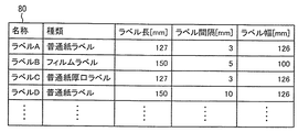
図12は実施例における媒体種類テーブルの説明図である。
図12において、媒体種類テーブル80は、連続媒体を、材質等の種類(媒体種類)、ラベル長、ラベル間隔、ラベル幅(媒体サイズ)等の画像形成条件に対応させてラベルピッチの基準値となる情報を記憶したテーブルであり、それぞれの連続媒体には名称が付与されている。ここで、ラベル長とは、図1に示すラベル紙20bに貼付されたラベルの図中矢印Bが示す媒体搬送方向における長さであり、ラベル間隔とは、ラベル紙20bに貼付された隣り合うラベル間の媒体搬送方向における距離(ラベルの後端と後続するラベルの先端との距離)であり、ラベル幅とは、ラベル紙20bに貼付されたラベルの媒体搬送方向と直交する方向の長さである。
FIG. 12 is an explanatory diagram of a medium type table in the embodiment.
In FIG. 12, the medium type table 80 indicates the reference value of the label pitch corresponding to the image forming conditions such as the type of material (medium type), the label length, the label interval, the label width (medium size), and the like. This table stores information, and a name is assigned to each continuous medium. Here, the label length is the length of the label affixed to the
また、ラベルAとラベルDのように、種類が同じであっても、ラベル長、ラベル間隔、ラベル幅等の媒体サイズが異なるものも存在する。
ユーザは、画像形成装置1で印刷する媒体の種類を、操作表示部としてのオペレーションパネルやホストPC2にインストールされたプリンタドライバ等のソフトウェアを介して媒体種類テーブル80から選択することにより、装填された媒体に適切な画像形成を行うことができる。
Also, there are labels such as label A and label D that have the same type but different media sizes such as label length, label interval, and label width.
The user selects the type of medium to be printed by the
図13は実施例における基準ラベルピッチテーブルの説明図である。
図13において、間隔情報記憶部としてのラベルピッチテーブル81は、図1に示す画像形成装置1がラベル紙20bを給紙する動作中またはトナー画像を形成する印刷動作中に、反射型書出し位置検知センサ36または透過型書出し位置検知センサ33により検出したラベル長とラベル間隔を加算した長さをラベルピッチ(図7または図9に示すラベルピッチLP)として連続媒体の名称毎に、即ち画像形成条件に対応させて記憶するテーブルである。
FIG. 13 is an explanatory diagram of a reference label pitch table in the embodiment.
In FIG. 13, a label pitch table 81 as an interval information storage unit detects the reflection type writing position during the operation of feeding the
ラベルピッチテーブル81は、画像形成条件に対応させ、連続媒体の名称毎のラベルピッチテーブル(例えば、ラベルAはラベルピッチテーブル811、ラベルBはラベルピッチテーブル812、ラベルCはラベルピッチテーブル813、ラベルDはラベルピッチテーブル814等)で構成されている。 The label pitch table 81 corresponds to the image forming conditions, and a label pitch table for each continuous medium name (for example, label A is a label pitch table 811, label B is a label pitch table 812, label C is a label pitch table 813, label D is a label pitch table 814).
また、ラベルピッチテーブル811は、環境温度の3水準、および環境湿度の3水準の合計9水準の組み合わせについて個別にブラックマークの間隔(ラベル長+ラベル間隔)をラベルピッチとして保持することができる。なお、各水準の数は、3水準に限られるものでなく、4水準以上、または2水準以下でも良く、また環境温度と環境湿度とで水準数が異なっていても良い。このように、ラベルピッチテーブル811は、温度センサ51および湿度センサ52で検知した環境温度および環境湿度に対応させてラベルピッチを記憶することができる。
Further, the label pitch table 811 can individually hold the black mark interval (label length + label interval) as a label pitch for a combination of nine levels of three levels of environmental temperature and three levels of environmental humidity. The number of each level is not limited to three levels, but may be four levels or more, or two levels or less, and the number of levels may be different between environmental temperature and environmental humidity. As described above, the label pitch table 811 can store the label pitch corresponding to the environmental temperature and the environmental humidity detected by the
なお、本実施例では、画像形成条件を材質等の媒体種類、ラベル長、ラベル間隔、およびラベル幅等の媒体サイズ、環境温度、並びに環境湿度としたが、媒体種類、媒体サイズ、環境温度、および環境湿度の少なくとも1つを含むものであれば良い。
ラベルピッチテーブル81の値は、書き換え可能であり、センサで検出したラベルピッチの値を更新することができるようになっている。
In this embodiment, the image forming conditions are medium type such as material, medium size such as label length, label interval, and label width, environmental temperature, and environmental humidity, but the medium type, medium size, environmental temperature, As long as it includes at least one of environmental humidity.
The value of the label pitch table 81 can be rewritten, and the value of the label pitch detected by the sensor can be updated.
図5に示すエンジン制御部71およびコマンド/画像処理部72は、画像形成条件に対応するラベルピッチテーブル81に記憶されたラベルピッチに基づいて図1に示す中間転写ベルト12にトナー画像を形成するタイミングを制御するとともに、反射型書出し位置検知センサ36または透過型書出し位置検知センサ33でラベルピッチを検知すると、検知したラベルピッチの情報に基づいてラベルピッチテーブル81のラベルピッチの情報を更新する。
The
また、図5に示すエンジン制御部71およびコマンド/画像処理部72は、図1に示す画像形成装置1がラベル紙20bを給紙する動作中またはトナー画像を形成する印刷動作中に、反射型書出し位置検知センサ36または透過型書出し位置検知センサ33によりラベルピッチを検知する。
Further, the
上述した構成の作用について説明する。
まず、画像形成装置の印刷動作を図1および図5を参照しながら説明する。
ラベルロール紙20aから引き出されたラベル紙20bは、2次転写ローラ16と2次転写バックアップローラ17とにより形成される2次転写部および定着部37を経由してリワインダー21に巻き取られる状態から印刷動作が開始される。本実施例の印刷は、ラベル紙20b上のラベルに連続的に画像を形成する、所謂Roll to Roll印刷である。
The operation of the above configuration will be described.
First, the printing operation of the image forming apparatus will be described with reference to FIGS.
The
なお、本実施例では、図8に示すように、ラベルロール紙20a(ラベル紙20b)には、各ラベルの先端部の台紙の裏面にブラックマークが印刷されているものとし、反射型書出し位置検知センサ36でブラックマークを検出してラベルピッチを検出するものとして説明する。
In this embodiment, as shown in FIG. 8, the
画像形成装置1のコマンド/画像処理部72は、インターフェース部73を介してホストPC2からコマンドおよび画像データを受信すると、画像形成動作を開始する。コマンド/画像処理部72は、受信したコマンドおよび画像データを解釈し、各トナー色のビットマップデータに展開し、展開したビットマップデータを画像メモリ75Y、75M、75C、75Kに書き込む。
また、コマンド/画像処理部72は、ビットマップデータへの展開と同時に、ホストPC2から受信したコマンドに応じてエンジン制御部71に印刷動作の開始の指示を出力する。
When the command /
In addition, the command /
エンジン制御部71は、ハロゲンヒータ40を制御して定着器37を温め、定着器37がトナー画像をラベル紙20bに定着できる温度の範囲になるように制御する。
定着器37が温まると、エンジン制御部71は、駆動ローラ13、画像形成ユニット2Y、2M、2C、2K、給紙ローラ28、第1中間搬送ローラ30、第2中間搬送ローラ32、定着ローラ38、およびリワインダー21の駆動を開始する。
The
When the fixing
駆動ローラ13が中間転写ベルト12を駆動する速度は、給紙ローラ28、第1中間搬送ローラ30、第2中間搬送ローラ32、定着ローラ38、およびリワインダー21がラベル紙20bを搬送する速度とほぼ同じである。
エンジン制御部71は、同時に高圧供給部74を制御して画像形成ユニット2Y、2M、2C、2K、および1次転写ローラ15Y、15M、15C、15Kに所定の高電圧バイアス(以下、「バイアス」という。)を供給する。
The speed at which the
The
ここで、感光体6Y、6M、6C、6Kへのトナー画像の形成動作について、画像形成ユニット2Kを例として図2を参照しながら説明する。
チャージローラ5Kには、高圧供給部74から−1000Vのチャージバイアスが供給され、感光体6Kの表面を−600Vに帯電させる。また、現像ローラ7Kには、−200Vの現像バイアスが、スポンジローラ7Kには、−250Vのスポンジバイアスが、高圧供給部74から供給される。
Here, a toner image forming operation on the
The
トナーカートリッジ10Kから供給されたトナーは、スポンジローラ9Kと現像ローラ7Kに強く擦られてマイナス極性に摩擦帯電する。マイナス極性に帯電されたトナーは、スポンジバイアスと現像バイアスの電位差によって現像ローラ7Kに付着する。
現像ローラ7Kに付着したトナーは、現像ブレード8Kによって均一な厚さにならされて、現像ローラ7Kにトナー層を形成する。現像ローラ7K上に形成されたトナー層は、現像ローラ7Kの回転によって感光体6Kとのニップ部に運ばれる。
The toner supplied from the
The toner adhering to the developing
一方、エンジン制御部71は、LEDヘッド3Kによる感光体6Kへの潜像の書き込みを開始する。エンジン制御部71は、画像メモリ75Kに書き込まれたブラック画像のビットマップデータを、画像の先端から順次読み出し、1ライン単位で順次LEDヘッド3Kに転送する。
LEDヘッド3Kは、転送されてきたビットマップデータに従ってLEDを点滅させ、−600Vに帯電された感光体6Kの表面を露光する。感光体6Kの露光された部分は、−50Vに除電され、静電潜像となる。
On the other hand, the
The
感光体6Kの静電潜像が形成された部分は、感光体6Kの回転に従って現像ローラ7Kとのニップ部に運ばれる。現像ローラ7K上にはマイナス帯電したトナー層が形成されており、また現像ローラ7Kには−200Vの現像バイアスが供給されているため、現像ローラ7Kと静電潜像との電位差により、静電潜像の部分にのみトナーが選択的に付着してトナー画像が現像される。
なお、画像形成ユニット2Y、2M、2Cにおいても同様に、感光体6Y、6M、6C上にトナー画像が形成される。
The portion of the
Similarly, in the
このように、感光体6Y、6M、6C、6K上にトナー画像が形成されると、当該トナー画像が中間転写ベルト12と感光体6Y、6M、6C、6Kとの接触部である1次転写部に到達する前に、高圧供給部74は1次転写ローラ15Y、15M、15C、15Kに1次転写バイアスを供給し、感光体6Y、6M、6C、6K上に形成されたトナー画像を中間転写ベルト12上に転写し、積層させる。なお、感光体6Y、6M、6C、6K上へのトナー画像の形成タイミングは、感光体6Y、6M、6C、6Kが配置された間隔分ずらして行われるため、トナー画像は中間転写ベルト12上では互いにずれることなく重なり合って積層される。
As described above, when a toner image is formed on the
次に、先頭画像のラベル紙への書出しタイミングの制御について図1および図5を参照しながら説明する。
上述したように、定着器37が温まると、中間転写ベルト12の走行速度と略同じ速度でラベル紙20bの搬送が開始される。同時に、エンジン制御部71は、温度センサ51および湿度センサ52により、環境温湿度を取得する。
Next, the control of the timing for writing the leading image onto the label paper will be described with reference to FIGS.
As described above, when the fixing
ラベル紙20bの搬送速度が目標速度に到達し、かつ速度が安定すると反射型書出し位置検知センサ36はラベル紙20bの裏面のブラックマークの検出を開始する。
ラベル紙20bの裏面のブラックマークの検出を開始した反射型書出し位置検知センサ36は、1個目のブラックマークを検知する。このブラックマークの先端は、ラベルの先端位置である。
When the conveyance speed of the
The reflection-type writing
1個目のブラックマークに対応するラベルを1枚目のラベルとし、中間転写ベルト12に転写された先頭のトナー画像が転写可能な最初のラベルをN枚目のラベルとすると、そのNは、エンジン制御部71およびコマンド/画像処理部72により、以下のように計算される。
図10に示すように、LEDヘッド3Yが感光体6Yを露光する位置から潜像および現像されたトナー画像が搬送される経路に沿って、2次転写位置までの距離をLHT、反射型書出し位置検知センサ36から2次転写位置までの距離をLSTとする。
If the label corresponding to the first black mark is the first label, and the first label to which the first toner image transferred to the
As shown in FIG. 10, the distance from the position where the
また、コマンド/画像処理部72は、基準ラベルピッチL0を基準となるラベルピッチテーブル81から取得する。このとき、コマンド/画像処理部72は、ラベル紙20bの種類に応じて基準となるラベルピッチテーブルを選択するものとし、例えばラベルAの場合、ラベルピッチテーブル811を選択する。さらに、コマンド/画像処理部72は、選択したラベルピッチテーブルと、温度センサ51および湿度センサ52で取得した環境温湿度とに基づいて基準ラベルピッチL0を取得する。
Further, the command /
このとき、Nは式1で計算される。
N=Roundup{(LHT−LST)/L0}+1 ・・・式1
なお、Roundupは小数点以下切り上げる関数を表している。
At this time, N is calculated by
N = Roundup {(LHT-LST) / L0} +1
Note that Roundup represents a function that rounds up after the decimal point.
次に、N枚目のラベルに、先頭のトナー画像を所定の位置に正しく転写するため、LED3Yが露光を開始するタイミングは以下のように計算される。1枚目のラベルのブラックマークを反射型書出し位置検知センサ36で検知してからLEDヘッド3Yが露光を開始するまでの距離をLFとすると、LFは、エンジン制御部71およびコマンド/画像処理部72により、式2に基づいて計算される。
Next, in order to correctly transfer the leading toner image to a predetermined position on the Nth label, the timing at which the
LF=(N−1)×L0−(LHT−LST) ・・・式2
ここで、式2で算出した距離LFは、ラベルピッチテーブル81に格納されていた基準ラベルピッチL0を使用しているため、実際の印刷時に反射型書出し位置検知センサ36で検知されるラベルピッチLとは誤差がある可能性がある。L0とLの誤差をΔLとすると、トナー画像の書出し位置は、(N−1)×ΔLだけずれてしまう。
LF = (N−1) × L0− (LHT−LST) Equation 2
Here, since the distance LF calculated by Expression 2 uses the reference label pitch L0 stored in the label pitch table 81, the label pitch L detected by the reflective writing
そこで、本実施例では、誤差ΔLをできる限り小さな値となるように、印刷動作中にラベルピッチテーブル81を更新するようにする。
図14は実施例における実測ラベルピッチテーブルの説明図であり、図13に示すラベルAのラベルピッチテーブル811を初期値とし、プレ給紙後、1回目印刷後、2回目印刷後等、順次ピッチテーブルを更新する様子を示している。
Therefore, in this embodiment, the label pitch table 81 is updated during the printing operation so that the error ΔL is as small as possible.
FIG. 14 is an explanatory diagram of the actually measured label pitch table in the embodiment. The label pitch table 811 for label A shown in FIG. 13 is set as an initial value, and the pitch is sequentially increased after pre-feeding, after first printing, after second printing, and the like. It shows how the table is updated.
まず、ラベルAを画像形成装置1が初めて印刷する場合について説明する。
上述したように、印刷開始前に、ラベル紙20bは2次転写ローラ16と2次転写バックアップローラ17とにより形成される2次転写部および定着部37を経由してリワインダー21に巻き取られる状態となっている。この印刷前の状態にするため、画像形成装置1は印刷開始前のプレ給紙動作を行う。
First, the case where the
As described above, before starting printing, the
プレ給紙動作を図11および図5に基づいて説明する。なお、図11(a)はプレ給紙動作を開始する前の状態を示し、図11(b)はプレ給紙動作を完了した後の状態を示している。
ユーザは、図11(a)に示すように、ラベルロール紙20aから引き出されたラベル紙20bの先端を給紙ローラ28とピンチローラ27とのニップ部に挿入する。その後、操作パネル等の操作部を操作してプレ給紙実行を指示するものとする。
The pre-feed operation will be described with reference to FIGS. FIG. 11A shows a state before starting the pre-feeding operation, and FIG. 11B shows a state after completing the pre-feeding operation.
As shown in FIG. 11A, the user inserts the leading end of the
エンジン制御部71は、駆動ローラ13、給紙ローラ28、第1中間搬送ローラ30、第2中間搬送ローラ32、および定着ローラ38の駆動を開始してラベル紙20bを搬送し、ラベル紙20bの先端が定着器37から十分に送り出された状態まで搬送して駆動を停止する。ユーザは、図11(b)に示すように、送り出されたラベル紙20bの先端部をリワインダー21(図中矢印Cが示す方向)に巻き付け、印刷可能な状態にしてプレ給紙動作を完了する。
The
エンジン制御部71は、このプレ給紙動作時に、反射型書出し位置検知センサ36でブラックマークを検出する。図11(b)に示すプレ給紙動作が完了する位置までラベル紙20bを搬送するまでの間に、ブラックマークを複数検出することができ、検出したブラックマークの間隔の平均値をL0とする。
The
プレ給紙動作を開始するとき、エンジン制御部71およびコマンド/画像処理部72は、ラベルピッチテーブル81を図12に示す媒体種類テーブル80の基準値に基づいて初期化する。したがって、プレ給紙動作前は、図14に示すラベルピッチテーブル811aには、図12に示す媒体種類テーブル80の基準値の情報に基づいてブラックマークの間隔(ラベル長+ラベル間隔)が初期値(例えば、130.00)として設定されている。媒体種類テーブル80の各値は、例えばラベルロール紙の製品仕様に基づいたものであり、印刷時に実際に検知される値とは誤差がある可能性がある。
When starting the pre-feed operation, the
プレ給紙動作後、エンジン制御部71およびコマンド/画像処理部72は、プレ給紙動作中に検出したブラックマークの間隔の平均値L0(例えば、130.12)でラベルピッチテーブル811aのすべての値を書き換え、プレ給紙後のラベルピッチテーブル811bとする。
After the pre-feeding operation, the
1回目の印刷動作では、プレ給紙後のラベルピッチテーブル811bのブラックマークの間隔L0を用いて上述した式2によって1枚目のラベルのブラックマークを反射型書出し位置検知センサ36で検知してからLEDヘッド3Yが露光を開始するまでの距離LFが、エンジン制御部71およびコマンド/画像処理部72により算出され、LEDヘッド3Yの露光タイミングが決定される。
In the first printing operation, the black mark interval L0 of the label pitch table 811b after pre-feeding is used to detect the black mark of the first label by the reflection type writing
1回目の印刷動作中、エンジン制御部71は、反射型書出し位置検知センサ36でブラックマークを検出し続け、同時に、ブラックマークの間隔を測定し、ラベルピッチ実測値列LKとしてRAM76に保持する。ラベルピッチ実測値列LKは、例えば最新のもの8個保持し、その平均値を印刷中に検知したラベルピッチ平均値LAVとする。
During the first printing operation, the
1回目の印刷動作終了後、エンジン制御部71は、ラベルピッチ平均値LAVをコマンド/画像処理部72に通知する。コマンド/画像処理部72は、ラベルピッチテーブル811bの該当する環境温度および環境湿度(例えば、環境温度15℃以上、25℃未満、環境湿度30%以上、70%未満)のラベルピッチを、エンジン制御部71から通知されたラベルピッチ平均値LAV(例えば、130.15)で書き換え、1回目印刷後のラベルピッチテーブル811cとする。
After the completion of the first printing operation, the
2回目以降の印刷動作が終了したときも、同様に印刷動作が終了する度に、コマンド/画像処理部72は、ラベルピッチテーブルの該当する環境温度および環境湿度(例えば、環境温度25℃より高い、環境湿度30%以上、70%未満)のラベルピッチを、エンジン制御部71から通知されたラベルピッチ平均値LAV(例えば、130.17)で書き換え、例えば2回目印刷後のラベルピッチテーブル811dとする。
When the second and subsequent printing operations are completed, each time the printing operation is similarly completed, the command /
このように、プレ給紙動作中や印刷動作中に反射型書出し位置検知センサ36で測定したブラックマークの間隔の実測値に基づいてラベルピッチテーブルを更新することにより、常に反射型書出し位置検知センサ36で測定したラベルピッチに近い値が維持され、先頭のトナー画像の書出し位置の誤差を最小限に抑えることができる。
ラベルピッチテーブルのラベルピッチを環境温湿度毎に保持するようにしているため、温湿度によるラベル紙20bの伸縮や搬送ローラ等のローラ類の膨張等による搬送量の変化も吸収してトナー画像の書出し位置の誤差を最小限に抑えることができる。
In this way, the reflective writing position detection sensor is always updated by updating the label pitch table based on the measured value of the black mark interval measured by the reflective writing
Since the label pitch of the label pitch table is held for each environmental temperature and humidity, changes in the conveyance amount due to expansion and contraction of the
さらに、ラベルピッチテーブルを媒体の種類毎に不揮発性の記憶部としてのFLASHメモリ77に保存するようにしたことにより、ラベルロール紙を交換した場合であっても、先頭のトナー画像の書出し位置の誤差を最小限に抑えることができる。
ここで、センサで測定した実測値に基づいてラベルピッチを更新しない場合に発生する問題を説明する。
Further, the label pitch table is stored in the
Here, a problem that occurs when the label pitch is not updated based on the actual measurement value measured by the sensor will be described.
中間転写方式を適用した電子写真方式の画像形成装置1において、ラベルロール紙やプレ印刷連続紙などの画像を形成する位置が指定されている連続媒体への画像形成を行う場合、連続媒体に画像を形成すべき位置と、実際に連続媒体に画像が形成される位置とがずれることがある。以下に、画像を形成する位置が指定されている連続媒体をラベルロール紙として説明するが、ラベルロール紙以外の「画像を形成する位置が指定されている連続媒体」であっても同様である。
In the electrophotographic
ラベルロール紙に画像を形成する中間転写方式の画像形成装置では、通常、媒体搬送方向における2次転写部の上流近傍(概ね、100mm以内)にセンサ等のラベル位置検知部材を配置し、ラベル位置の検出結果に基づいて画像位置や画像形成ピッチを調整するようにしている。これは、2次転写部近傍でラベルの位置を検知することにより、2次転写位置での媒体搬送速度でラベル位置の検知が可能となり、正確なラベル位置の検知が行えるためである。 In an intermediate transfer type image forming apparatus that forms an image on label roll paper, a label position detection member such as a sensor is usually arranged in the vicinity of the secondary transfer section in the medium conveyance direction (generally within 100 mm), and the label position The image position and the image formation pitch are adjusted based on the detection result. This is because the label position can be detected at the medium transfer speed at the secondary transfer position by detecting the label position in the vicinity of the secondary transfer portion, and the label position can be accurately detected.
一方、中間転写方式の画像形成装置1は、2次転写位置から中間転写ベルト12の走行方向における最上流に位置するLEDヘッド3Yの露光源までの距離は、中間転写ベルト12の半周程度、またはそれ以上の約数百mm程度であり、2次転写位置からラベル位置検知部材までの距離より長いのが通常である。そのため、実際にトナー画像が転写されるラベルの位置を検知する前にLEDヘッド3Yの露光を開始する必要がある。
On the other hand, in the intermediate transfer type
このように、トナー画像が転写されるラベルの位置を検知する前にLEDヘッド3Yの露光を開始するようにしているため、露光開始タイミングはトナー画像が転写されるラベルではなく、より下流のラベル位置の検知結果を基準として推測により決定される。
例えば、基準となる下流のラベルを1枚目として、トナー画像が転写されるラベルがN枚目とすると、トナー画像が転写されるラベルの位置は、平均的なラベルピッチをPとし、基準ラベル位置よりP×(N−1)だけ上流にあると推測し、露光開始タイミングを決定する。
Thus, since the exposure of the
For example, if the downstream label serving as a reference is the first sheet and the label to which the toner image is transferred is the Nth sheet, the label position to which the toner image is transferred is P, and the average label pitch is P. It is estimated that P × (N−1) is upstream from the position, and the exposure start timing is determined.
しかしながら、このような方法では、平均的なラベルピッチPが実際に画像を形成するときのラベルピッチP´との誤差が充分に小さくないと、トナー画像が実際に転写されるラベルでの画像の位置ずれが大きくなってしまう。例えば、N=5となるようなラベルピッチのラベルロール紙に印刷する場合、PとP´の誤差が0.2mmとすると、トナー画像の書出し位置は0.2×(5−1)=0.8mmもずれてしまう。 However, in such a method, if the error between the average label pitch P and the label pitch P ′ when the image is actually formed is not sufficiently small, the image of the image on the label to which the toner image is actually transferred is not. Misalignment will increase. For example, when printing on label roll paper with a label pitch such that N = 5, if the error between P and P ′ is 0.2 mm, the toner image writing position is 0.2 × (5-1) = 0. It will shift by 8mm.
このような問題に鑑み、本実施例では、プレ給紙動作中や印刷動作中に反射型書出し位置検知センサ36で測定したブラックマークの間隔の実測値に基づいてラベルピッチテーブルを更新し、常に反射型書出し位置検知センサ36で測定したラベルピッチに近い値を維持し、先頭のトナー画像の書出し位置の誤差を最小限に抑えるようにしている。
In view of such a problem, in this embodiment, the label pitch table is updated based on the actual measurement value of the black mark interval measured by the reflection type writing
なお、本実施例では、反射型書出し位置検知センサ36でブラックマークを検出してラベルピッチを検出するものとして説明したが、図6に示すように、連続した台紙47に、所定の間隔を保持して複数のラベル46が貼付されているラベル紙20b(ラベル46間には、台紙47のみが存在し、ラベルカスは存在しないラベル紙20b)を使用し、透過型書出し位置検知センサ33でラベルピッチを検出するようにしても良い。
また、トナー画像を転写する位置が予め決められたプレ印刷紙を使用し、反射型書出し位置検知センサ36でブラックマークを検出し、ラベルピッチを検出するようにしても良い。
In the present embodiment, the reflective writing
Alternatively, pre-printed paper with a predetermined transfer position for the toner image may be used, and the black mark may be detected by the reflective writing
以上説明したように、本実施例では、プレ給紙動作中や印刷動作中に反射型書出し位置検知センサで測定したブラックマークの間隔の実測値に基づいてラベルピッチテーブルを更新し、ブラックマークの間隔の実測値に基づいて先頭のトナー画像の形成開始タイミングを算出するようにしたことにより、先頭のトナー画像の書出し位置の誤差を最小限に抑えることができるという効果が得られる。 As described above, in this embodiment, the label pitch table is updated based on the actual measurement value of the black mark interval measured by the reflective writing position detection sensor during the pre-feeding operation or the printing operation. By calculating the formation start timing of the leading toner image based on the measured value of the interval, an effect of minimizing the error in the writing position of the leading toner image can be obtained.
また、ラベルピッチテーブルのラベルピッチを環境温湿度毎に保持するようにしたことにより、印刷動作時の環境湿度が変化しても先頭のトナー画像の書出し位置の誤差を最小限に抑えることができるという効果が得られる。
なお、本実施例では、画像形成装置をプリンタとして説明したが、それに限られるものでなく、複写機、ファクシミリ装置、複合機(MFP)等としても良い。
In addition, by maintaining the label pitch of the label pitch table for each environmental temperature and humidity, even if the environmental humidity during the printing operation changes, the error in the writing position of the leading toner image can be minimized. The effect is obtained.
In this embodiment, the image forming apparatus has been described as a printer. However, the image forming apparatus is not limited thereto, and may be a copier, a facsimile machine, a multifunction peripheral (MFP), or the like.
1 画像形成装置
2Y、2M、2C、2K 画像形成ユニット
3Y、3M、3C、3K LEDヘッド
6Y、6M、6C、6K 感光体
12 中間転写ベルト
13 駆動ローラ
15Y、15M、15C、15K 1次転写ローラ
16 2次転写ローラ
17 2次転写バックアップローラ
20a ラベルロール紙
20b ラベル紙
21 リワインダー
22 透過型カット位置検知センサ
25 反射型カット位置検知センサ
28 給紙ローラ
30 第1中間搬送ローラ
32 第2中間搬送ローラ
33 透過型書出し位置検知センサ
36 反射型書出し位置検知センサ
37 定着器
46 ラベル
47 台紙
51 温度センサ
52 湿度センサ
71 エンジン制御部
72 コマンド/画像処理部
73 インターフェース部
74 高圧供給部
75Y、75M、75C、75K 画像メモリ
76 RAM
77 FLASHメモリ
81 ラベルピッチテーブル
DESCRIPTION OF
77
Claims (9)
前記像担持体に形成された静電潜像に現像剤を供給することにより現像剤像を形成する現像部と、
前記像担持体に形成された現像剤像を中間転写体に転写する1次転写部と、
台紙上に間隔をおいて設けられた複数のラベルを備える連続媒体を搬送する搬送部と、
搬送される連続媒体に中間転写体に形成された現像剤像を転写する2次転写部と、
連続媒体の搬送方向における前記2次転写部の上流に配置され、通過する連続媒体のラベルにおける前記現像剤像を転写する位置の間隔を検知する間隔検知部と、
前記間隔検知部が検知した前記間隔を間隔情報として記憶する間隔情報記憶部と、
前記間隔情報記憶部に記憶された間隔情報に基づいて前記像担持体に静電潜像を形成するタイミングを制御するとともに、前記間隔検知部で検知した前記間隔に基づいて前記間隔情報記憶部の間隔情報を更新する制御部と、
を有し、
前記間隔情報記憶部は、画像形成条件に対応させて前記間隔情報を記憶する領域を有し、
前記制御部は、
前記連続媒体を給紙する前に、前記間隔情報記憶部に記憶された間隔情報を前記画像形成条件毎の基準値で初期化し、
前記間隔検知部で検知した前記間隔であって前記間隔検知部を順次通過したラベルの前記間隔の平均値に基づいて前記画像形成条件に対応する前記間隔情報記憶部の間隔情報を更新し、
前記間隔検知部で間隔が検知されたラベルの後に順次搬送されて前記2次転写部に到達するそれぞれのラベルに対し、更新された前記間隔情報に基づいて、現像剤像を転写する位置に合わせるように、前記露光部による前記像担持体に形成する静電潜像の形成タイミングを制御することを特徴とする画像形成装置。 An exposure unit for forming an electrostatic latent image on a charged image carrier;
A developing unit for forming a developer image by supplying a developer to the electrostatic latent image formed on the image carrier;
A primary transfer portion for transferring a developer image formed on the image carrier to an intermediate transfer member;
A transport unit for transporting a continuous medium having a plurality of labels provided at intervals on the mount;
A secondary transfer unit that transfers the developer image formed on the intermediate transfer member to a continuous medium to be conveyed;
An interval detection unit that is disposed upstream of the secondary transfer unit in the conveyance direction of the continuous medium and detects an interval of a position at which the developer image is transferred on a label of the continuous medium that passes through;
An interval information storage unit that stores the interval detected by the interval detection unit as interval information;
The timing of forming an electrostatic latent image on the image carrier is controlled based on the interval information stored in the interval information storage unit, and the interval information storage unit is controlled based on the interval detected by the interval detection unit. A control unit for updating the interval information;
Have
The interval information storage unit has an area for storing the interval information in correspondence with image forming conditions,
The controller is
Before feeding the continuous medium, the interval information stored in the interval information storage unit is initialized with a reference value for each image forming condition ,
Updates the distance information of the distance information storage unit corresponding to the image forming conditions based on the average value of the interval of labels sequentially passes through the interval detection unit an the distance detected by the distance detecting unit,
Based on the updated interval information, the developer image is transferred to the position where each label which is sequentially conveyed after the label whose interval is detected by the interval detection unit and reaches the secondary transfer unit is transferred. As described above, the image forming apparatus controls the formation timing of the electrostatic latent image formed on the image carrier by the exposure unit.
前記制御部は、前記連続媒体を給紙する動作中または前記現像剤像を形成する動作中に、前記間隔検知部で前記間隔を検知することを特徴とする画像形成装置。 The image forming apparatus according to claim 1.
The control unit detects the interval by the interval detection unit during an operation of feeding the continuous medium or an operation of forming the developer image.
前記画像形成条件は、媒体種類、媒体サイズ、環境温度、および環境湿度の少なくとも1つを含むことを特徴とする画像形成装置。 The image forming apparatus according to claim 1 , wherein:
The image forming apparatus includes at least one of a medium type, a medium size, an environmental temperature, and an environmental humidity.
さらに、環境温度を検知する温度検知部を有し、
前記間隔情報記憶部は、環境温度に対応させて前記間隔情報を記憶する領域を有し、
前記制御部は、前記温度検知部で検知した環境温度に対応させて前記間隔情報記憶部に前記更新した間隔情報を記憶させるとともに、更新した間隔情報に基づいて前記露光部による前記像担持体に形成する静電潜像の形成タイミングを制御することを特徴とする画像形成装置。 The image forming apparatus according to any one of claims 1 to 3 ,
Furthermore, it has a temperature detection part that detects the environmental temperature,
The interval information storage unit has an area for storing the interval information corresponding to an environmental temperature,
The control unit stores the updated interval information in the interval information storage unit in association with the environmental temperature detected by the temperature detection unit, and the exposure unit sets the image carrier by the exposure unit based on the updated interval information. An image forming apparatus that controls the formation timing of an electrostatic latent image to be formed.
さらに、環境湿度を検知する湿度検知部を有し、
前記間隔情報記憶部は、環境湿度に対応させて前記間隔情報を記憶する領域を有し、
前記制御部は、前記湿度検知部で検知した環境湿度に対応させて前記間隔情報記憶部に前記間隔情報を記憶させるとともに、更新した間隔情報に基づいて前記露光部による前記像担持体に形成する静電潜像の形成タイミングを制御することを特徴とする画像形成装置。 5. The image forming apparatus according to claim 1 , wherein:
Furthermore, it has a humidity detector that detects environmental humidity,
The interval information storage unit has an area for storing the interval information corresponding to environmental humidity,
The control unit stores the interval information in the interval information storage unit in correspondence with the environmental humidity detected by the humidity detection unit, and forms the image carrier by the exposure unit based on the updated interval information. An image forming apparatus that controls formation timing of an electrostatic latent image.
前記間隔検知部は、反射型の光学センサであることを特徴とする画像形成装置。 The image forming apparatus according to claim 1 , wherein:
The image forming apparatus, wherein the interval detection unit is a reflective optical sensor.
前記間隔検知部は、透過型の光学センサであることを特徴とする画像形成装置。 The image forming apparatus according to claim 1 , wherein:
The image forming apparatus, wherein the interval detection unit is a transmissive optical sensor.
前記連続媒体は、複数のラベルが間隔をおいて台紙に貼付されたラベルロール紙であることを特徴とする画像形成装置。 The image forming apparatus according to any one of claims 1 to 7 ,
The image forming apparatus, wherein the continuous medium is a label roll paper in which a plurality of labels are affixed to a mount at intervals.
前記連続媒体は、前記現像剤像を転写する位置が予め決められたプレ印刷紙であることを特徴とする画像形成装置。 The image forming apparatus according to any one of claims 1 to 7 ,
2. The image forming apparatus according to claim 1, wherein the continuous medium is preprinted paper at a position where the developer image is transferred.
Priority Applications (2)
| Application Number | Priority Date | Filing Date | Title |
|---|---|---|---|
| JP2016020834A JP6577880B2 (en) | 2016-02-05 | 2016-02-05 | Image forming apparatus |
| US15/410,638 US10108112B2 (en) | 2016-02-05 | 2017-01-19 | Image forming apparatus that adjusts image formation timing based on image transfer position |
Applications Claiming Priority (1)
| Application Number | Priority Date | Filing Date | Title |
|---|---|---|---|
| JP2016020834A JP6577880B2 (en) | 2016-02-05 | 2016-02-05 | Image forming apparatus |
Publications (3)
| Publication Number | Publication Date |
|---|---|
| JP2017138548A JP2017138548A (en) | 2017-08-10 |
| JP2017138548A5 JP2017138548A5 (en) | 2018-06-28 |
| JP6577880B2 true JP6577880B2 (en) | 2019-09-18 |
Family
ID=59496222
Family Applications (1)
| Application Number | Title | Priority Date | Filing Date |
|---|---|---|---|
| JP2016020834A Active JP6577880B2 (en) | 2016-02-05 | 2016-02-05 | Image forming apparatus |
Country Status (2)
| Country | Link |
|---|---|
| US (1) | US10108112B2 (en) |
| JP (1) | JP6577880B2 (en) |
Families Citing this family (3)
| Publication number | Priority date | Publication date | Assignee | Title |
|---|---|---|---|---|
| JP6868519B2 (en) | 2017-09-21 | 2021-05-12 | 株式会社沖データ | Image forming device |
| EP3492269A1 (en) * | 2017-11-29 | 2019-06-05 | OCE Holding B.V. | A media roll comprising a main medium and a support medium |
| JP7127435B2 (en) | 2018-08-31 | 2022-08-30 | 沖電気工業株式会社 | Image forming apparatus and image forming method |
Family Cites Families (13)
| Publication number | Priority date | Publication date | Assignee | Title |
|---|---|---|---|---|
| JPS5457850A (en) * | 1977-10-17 | 1979-05-10 | Chino Works Ltd | Sequential movement mean circuit |
| JPH0419475Y2 (en) * | 1985-12-25 | 1992-05-01 | ||
| JPH06171798A (en) * | 1992-12-11 | 1994-06-21 | Casio Electron Mfg Co Ltd | Label paper sheet detecting device |
| US5991563A (en) * | 1997-08-06 | 1999-11-23 | Konica Corporation | Image forming apparatus |
| DE102004029943B4 (en) * | 2004-06-21 | 2006-04-27 | OCé PRINTING SYSTEMS GMBH | Printer or copier for printing on an endless carrier material with transverse folds and method for controlling such a printer or copier |
| JP2006272769A (en) * | 2005-03-29 | 2006-10-12 | Konica Minolta Business Technologies Inc | Image forming device |
| JP4732946B2 (en) * | 2006-04-28 | 2011-07-27 | Aiソリューションズ株式会社 | Page pitch detection method, page pitch detection device and printer |
| JP5386881B2 (en) * | 2008-08-07 | 2014-01-15 | セイコーエプソン株式会社 | Label paper cueing control method and label printer |
| JP5473433B2 (en) * | 2009-06-30 | 2014-04-16 | キヤノン株式会社 | Image forming apparatus |
| JP5941819B2 (en) | 2012-10-19 | 2016-06-29 | 株式会社沖データ | Medium feeding control method, medium feeding apparatus, and image forming apparatus |
| JP6136691B2 (en) * | 2013-07-19 | 2017-05-31 | ブラザー工業株式会社 | Image forming apparatus |
| JP5786078B1 (en) * | 2014-09-08 | 2015-09-30 | グラフテック株式会社 | Printing system |
| JP6124148B2 (en) * | 2014-12-18 | 2017-05-10 | カシオ計算機株式会社 | Image forming apparatus |
-
2016
- 2016-02-05 JP JP2016020834A patent/JP6577880B2/en active Active
-
2017
- 2017-01-19 US US15/410,638 patent/US10108112B2/en active Active
Also Published As
| Publication number | Publication date |
|---|---|
| US10108112B2 (en) | 2018-10-23 |
| US20170227893A1 (en) | 2017-08-10 |
| JP2017138548A (en) | 2017-08-10 |
Similar Documents
| Publication | Publication Date | Title |
|---|---|---|
| JP5750630B2 (en) | Image forming apparatus | |
| JP2005017422A (en) | Image forming apparatus | |
| JP6577880B2 (en) | Image forming apparatus | |
| JP2019078942A (en) | Image forming system | |
| JP5591274B2 (en) | Developing device and image forming apparatus | |
| US10520873B2 (en) | Image forming apparatus and image forming method | |
| JP5939121B2 (en) | Image forming apparatus | |
| JP2015208890A (en) | Image formation apparatus | |
| JP2015051816A (en) | Print device, supply device of recording medium, skew correction method of recording medium, and program | |
| JP6372191B2 (en) | Image forming apparatus | |
| JP7135784B2 (en) | MEDIUM THICKNESS DETECTION DEVICE, MEDIUM CONVEYING DEVICE, AND IMAGE FORMING APPARATUS | |
| JP5188554B2 (en) | Color image forming apparatus | |
| JP6950523B2 (en) | Image forming device | |
| JP6450657B2 (en) | Image forming apparatus | |
| JP6499114B2 (en) | Image forming apparatus and image forming method | |
| JP2017181937A (en) | Image formation apparatus | |
| US11163252B2 (en) | Image forming apparatus and image position adjustment method | |
| US20230046358A1 (en) | Image forming apparatus and conveyance control method | |
| JP6276660B2 (en) | Medium transport mechanism, fixing device, and image forming apparatus | |
| JP4710346B2 (en) | Image forming apparatus and color misregistration correction method | |
| JP2020086258A (en) | Image forming device | |
| JP6868519B2 (en) | Image forming device | |
| JP5975491B2 (en) | Developing device and image forming apparatus | |
| JP2022062417A (en) | Image formation apparatus | |
| JP2016175718A (en) | Medium conveyance device and image formation apparatus |
Legal Events
| Date | Code | Title | Description |
|---|---|---|---|
| A521 | Request for written amendment filed |
Free format text: JAPANESE INTERMEDIATE CODE: A523 Effective date: 20180517 |
|
| A621 | Written request for application examination |
Free format text: JAPANESE INTERMEDIATE CODE: A621 Effective date: 20180517 |
|
| A977 | Report on retrieval |
Free format text: JAPANESE INTERMEDIATE CODE: A971007 Effective date: 20190227 |
|
| A131 | Notification of reasons for refusal |
Free format text: JAPANESE INTERMEDIATE CODE: A131 Effective date: 20190312 |
|
| A521 | Request for written amendment filed |
Free format text: JAPANESE INTERMEDIATE CODE: A523 Effective date: 20190513 |
|
| A131 | Notification of reasons for refusal |
Free format text: JAPANESE INTERMEDIATE CODE: A131 Effective date: 20190528 |
|
| A521 | Request for written amendment filed |
Free format text: JAPANESE INTERMEDIATE CODE: A523 Effective date: 20190711 |
|
| TRDD | Decision of grant or rejection written | ||
| A01 | Written decision to grant a patent or to grant a registration (utility model) |
Free format text: JAPANESE INTERMEDIATE CODE: A01 Effective date: 20190730 |
|
| A61 | First payment of annual fees (during grant procedure) |
Free format text: JAPANESE INTERMEDIATE CODE: A61 Effective date: 20190823 |
|
| R150 | Certificate of patent or registration of utility model |
Ref document number: 6577880 Country of ref document: JP Free format text: JAPANESE INTERMEDIATE CODE: R150 |
|
| S111 | Request for change of ownership or part of ownership |
Free format text: JAPANESE INTERMEDIATE CODE: R313111 |
|
| R350 | Written notification of registration of transfer |
Free format text: JAPANESE INTERMEDIATE CODE: R350 |