JP6576695B2 - Catheter with side-by-side loops in the distal compartment - Google Patents
Catheter with side-by-side loops in the distal compartment Download PDFInfo
- Publication number
- JP6576695B2 JP6576695B2 JP2015109580A JP2015109580A JP6576695B2 JP 6576695 B2 JP6576695 B2 JP 6576695B2 JP 2015109580 A JP2015109580 A JP 2015109580A JP 2015109580 A JP2015109580 A JP 2015109580A JP 6576695 B2 JP6576695 B2 JP 6576695B2
- Authority
- JP
- Japan
- Prior art keywords
- configuration
- loop
- catheter
- distal
- proximal
- Prior art date
- Legal status (The legal status is an assumption and is not a legal conclusion. Google has not performed a legal analysis and makes no representation as to the accuracy of the status listed.)
- Expired - Fee Related
Links
- 210000003492 pulmonary vein Anatomy 0.000 description 18
- 239000011248 coating agent Substances 0.000 description 16
- 238000000576 coating method Methods 0.000 description 16
- 239000000853 adhesive Substances 0.000 description 15
- 230000001070 adhesive effect Effects 0.000 description 15
- 230000006835 compression Effects 0.000 description 12
- 238000007906 compression Methods 0.000 description 12
- 239000000463 material Substances 0.000 description 12
- WABPQHHGFIMREM-UHFFFAOYSA-N lead(0) Chemical compound [Pb] WABPQHHGFIMREM-UHFFFAOYSA-N 0.000 description 11
- PXHVJJICTQNCMI-UHFFFAOYSA-N Nickel Chemical compound [Ni] PXHVJJICTQNCMI-UHFFFAOYSA-N 0.000 description 8
- 238000013507 mapping Methods 0.000 description 8
- 239000004814 polyurethane Substances 0.000 description 8
- 229920002635 polyurethane Polymers 0.000 description 8
- 210000001519 tissue Anatomy 0.000 description 8
- 210000005246 left atrium Anatomy 0.000 description 7
- 239000010935 stainless steel Substances 0.000 description 7
- 229910001220 stainless steel Inorganic materials 0.000 description 7
- 238000002679 ablation Methods 0.000 description 6
- BASFCYQUMIYNBI-UHFFFAOYSA-N platinum Chemical compound [Pt] BASFCYQUMIYNBI-UHFFFAOYSA-N 0.000 description 6
- 206010003119 arrhythmia Diseases 0.000 description 4
- 239000004033 plastic Substances 0.000 description 4
- 229920003023 plastic Polymers 0.000 description 4
- 230000001681 protective effect Effects 0.000 description 4
- 239000004642 Polyimide Substances 0.000 description 3
- 239000004809 Teflon Substances 0.000 description 3
- 229920006362 Teflon® Polymers 0.000 description 3
- 230000006793 arrhythmia Effects 0.000 description 3
- 230000000694 effects Effects 0.000 description 3
- 229910052751 metal Inorganic materials 0.000 description 3
- 239000002184 metal Substances 0.000 description 3
- 238000000034 method Methods 0.000 description 3
- 229910052697 platinum Inorganic materials 0.000 description 3
- 229920001721 polyimide Polymers 0.000 description 3
- 230000002685 pulmonary effect Effects 0.000 description 3
- 125000006850 spacer group Chemical group 0.000 description 3
- 206010003658 Atrial Fibrillation Diseases 0.000 description 2
- RYGMFSIKBFXOCR-UHFFFAOYSA-N Copper Chemical group [Cu] RYGMFSIKBFXOCR-UHFFFAOYSA-N 0.000 description 2
- 229910000990 Ni alloy Inorganic materials 0.000 description 2
- 229920002614 Polyether block amide Polymers 0.000 description 2
- 229910001069 Ti alloy Inorganic materials 0.000 description 2
- RTAQQCXQSZGOHL-UHFFFAOYSA-N Titanium Chemical compound [Ti] RTAQQCXQSZGOHL-UHFFFAOYSA-N 0.000 description 2
- 238000013459 approach Methods 0.000 description 2
- 230000000903 blocking effect Effects 0.000 description 2
- 239000004020 conductor Substances 0.000 description 2
- 238000010276 construction Methods 0.000 description 2
- 238000002594 fluoroscopy Methods 0.000 description 2
- PCHJSUWPFVWCPO-UHFFFAOYSA-N gold Chemical compound [Au] PCHJSUWPFVWCPO-UHFFFAOYSA-N 0.000 description 2
- 229910052737 gold Inorganic materials 0.000 description 2
- 239000010931 gold Substances 0.000 description 2
- 210000002837 heart atrium Anatomy 0.000 description 2
- 210000005003 heart tissue Anatomy 0.000 description 2
- 229910052741 iridium Inorganic materials 0.000 description 2
- GKOZUEZYRPOHIO-UHFFFAOYSA-N iridium atom Chemical compound [Ir] GKOZUEZYRPOHIO-UHFFFAOYSA-N 0.000 description 2
- 229910052759 nickel Inorganic materials 0.000 description 2
- 229910001000 nickel titanium Inorganic materials 0.000 description 2
- HLXZNVUGXRDIFK-UHFFFAOYSA-N nickel titanium Chemical compound [Ti].[Ti].[Ti].[Ti].[Ti].[Ti].[Ti].[Ti].[Ti].[Ti].[Ti].[Ni].[Ni].[Ni].[Ni].[Ni].[Ni].[Ni].[Ni].[Ni].[Ni].[Ni].[Ni].[Ni].[Ni] HLXZNVUGXRDIFK-UHFFFAOYSA-N 0.000 description 2
- 230000037361 pathway Effects 0.000 description 2
- 210000005245 right atrium Anatomy 0.000 description 2
- 239000010936 titanium Substances 0.000 description 2
- 229910052719 titanium Inorganic materials 0.000 description 2
- 229910001006 Constantan Inorganic materials 0.000 description 1
- 239000004593 Epoxy Substances 0.000 description 1
- 238000010521 absorption reaction Methods 0.000 description 1
- 238000004026 adhesive bonding Methods 0.000 description 1
- 230000002411 adverse Effects 0.000 description 1
- 229910045601 alloy Inorganic materials 0.000 description 1
- 239000000956 alloy Substances 0.000 description 1
- 238000004873 anchoring Methods 0.000 description 1
- 230000001746 atrial effect Effects 0.000 description 1
- 230000005540 biological transmission Effects 0.000 description 1
- 238000009954 braiding Methods 0.000 description 1
- 230000000747 cardiac effect Effects 0.000 description 1
- 230000008859 change Effects 0.000 description 1
- 230000007797 corrosion Effects 0.000 description 1
- 238000005260 corrosion Methods 0.000 description 1
- 238000005520 cutting process Methods 0.000 description 1
- 230000006378 damage Effects 0.000 description 1
- 238000001514 detection method Methods 0.000 description 1
- 238000003745 diagnosis Methods 0.000 description 1
- 229910003460 diamond Inorganic materials 0.000 description 1
- 239000010432 diamond Substances 0.000 description 1
- 230000008020 evaporation Effects 0.000 description 1
- 238000001704 evaporation Methods 0.000 description 1
- 238000010884 ion-beam technique Methods 0.000 description 1
- 230000003902 lesion Effects 0.000 description 1
- 238000012986 modification Methods 0.000 description 1
- 230000004048 modification Effects 0.000 description 1
- 238000012544 monitoring process Methods 0.000 description 1
- 230000002107 myocardial effect Effects 0.000 description 1
- 230000007935 neutral effect Effects 0.000 description 1
- 231100000956 nontoxicity Toxicity 0.000 description 1
- 230000008569 process Effects 0.000 description 1
- 210000001147 pulmonary artery Anatomy 0.000 description 1
- 230000033764 rhythmic process Effects 0.000 description 1
- 239000007787 solid Substances 0.000 description 1
- 238000004544 sputter deposition Methods 0.000 description 1
- 238000007920 subcutaneous administration Methods 0.000 description 1
- BFKJFAAPBSQJPD-UHFFFAOYSA-N tetrafluoroethene Chemical compound FC(F)=C(F)F BFKJFAAPBSQJPD-UHFFFAOYSA-N 0.000 description 1
- 238000002560 therapeutic procedure Methods 0.000 description 1
- 238000011282 treatment Methods 0.000 description 1
- 210000003462 vein Anatomy 0.000 description 1
- 238000003466 welding Methods 0.000 description 1
Images


Classifications
-
- A—HUMAN NECESSITIES
- A61—MEDICAL OR VETERINARY SCIENCE; HYGIENE
- A61B—DIAGNOSIS; SURGERY; IDENTIFICATION
- A61B18/00—Surgical instruments, devices or methods for transferring non-mechanical forms of energy to or from the body
- A61B18/04—Surgical instruments, devices or methods for transferring non-mechanical forms of energy to or from the body by heating
- A61B18/12—Surgical instruments, devices or methods for transferring non-mechanical forms of energy to or from the body by heating by passing a current through the tissue to be heated, e.g. high-frequency current
- A61B18/14—Probes or electrodes therefor
- A61B18/1492—Probes or electrodes therefor having a flexible, catheter-like structure, e.g. for heart ablation
-
- A—HUMAN NECESSITIES
- A61—MEDICAL OR VETERINARY SCIENCE; HYGIENE
- A61B—DIAGNOSIS; SURGERY; IDENTIFICATION
- A61B5/00—Measuring for diagnostic purposes; Identification of persons
- A61B5/24—Detecting, measuring or recording bioelectric or biomagnetic signals of the body or parts thereof
- A61B5/25—Bioelectric electrodes therefor
- A61B5/279—Bioelectric electrodes therefor specially adapted for particular uses
- A61B5/28—Bioelectric electrodes therefor specially adapted for particular uses for electrocardiography [ECG]
- A61B5/283—Invasive
- A61B5/287—Holders for multiple electrodes, e.g. electrode catheters for electrophysiological study [EPS]
-
- A—HUMAN NECESSITIES
- A61—MEDICAL OR VETERINARY SCIENCE; HYGIENE
- A61B—DIAGNOSIS; SURGERY; IDENTIFICATION
- A61B5/00—Measuring for diagnostic purposes; Identification of persons
- A61B5/68—Arrangements of detecting, measuring or recording means, e.g. sensors, in relation to patient
- A61B5/6846—Arrangements of detecting, measuring or recording means, e.g. sensors, in relation to patient specially adapted to be brought in contact with an internal body part, i.e. invasive
- A61B5/6847—Arrangements of detecting, measuring or recording means, e.g. sensors, in relation to patient specially adapted to be brought in contact with an internal body part, i.e. invasive mounted on an invasive device
- A61B5/6852—Catheters
- A61B5/6856—Catheters with a distal loop
-
- A—HUMAN NECESSITIES
- A61—MEDICAL OR VETERINARY SCIENCE; HYGIENE
- A61B—DIAGNOSIS; SURGERY; IDENTIFICATION
- A61B18/00—Surgical instruments, devices or methods for transferring non-mechanical forms of energy to or from the body
- A61B2018/00053—Mechanical features of the instrument of device
- A61B2018/0016—Energy applicators arranged in a two- or three dimensional array
-
- A—HUMAN NECESSITIES
- A61—MEDICAL OR VETERINARY SCIENCE; HYGIENE
- A61B—DIAGNOSIS; SURGERY; IDENTIFICATION
- A61B18/00—Surgical instruments, devices or methods for transferring non-mechanical forms of energy to or from the body
- A61B2018/00315—Surgical instruments, devices or methods for transferring non-mechanical forms of energy to or from the body for treatment of particular body parts
- A61B2018/00345—Vascular system
- A61B2018/00351—Heart
- A61B2018/00375—Ostium, e.g. ostium of pulmonary vein or artery
-
- A—HUMAN NECESSITIES
- A61—MEDICAL OR VETERINARY SCIENCE; HYGIENE
- A61B—DIAGNOSIS; SURGERY; IDENTIFICATION
- A61B18/00—Surgical instruments, devices or methods for transferring non-mechanical forms of energy to or from the body
- A61B2018/00571—Surgical instruments, devices or methods for transferring non-mechanical forms of energy to or from the body for achieving a particular surgical effect
- A61B2018/00577—Ablation
-
- A—HUMAN NECESSITIES
- A61—MEDICAL OR VETERINARY SCIENCE; HYGIENE
- A61B—DIAGNOSIS; SURGERY; IDENTIFICATION
- A61B18/00—Surgical instruments, devices or methods for transferring non-mechanical forms of energy to or from the body
- A61B2018/00636—Sensing and controlling the application of energy
- A61B2018/00642—Sensing and controlling the application of energy with feedback, i.e. closed loop control
-
- A—HUMAN NECESSITIES
- A61—MEDICAL OR VETERINARY SCIENCE; HYGIENE
- A61B—DIAGNOSIS; SURGERY; IDENTIFICATION
- A61B18/00—Surgical instruments, devices or methods for transferring non-mechanical forms of energy to or from the body
- A61B2018/00636—Sensing and controlling the application of energy
- A61B2018/00773—Sensed parameters
- A61B2018/00839—Bioelectrical parameters, e.g. ECG, EEG
-
- A—HUMAN NECESSITIES
- A61—MEDICAL OR VETERINARY SCIENCE; HYGIENE
- A61B—DIAGNOSIS; SURGERY; IDENTIFICATION
- A61B18/00—Surgical instruments, devices or methods for transferring non-mechanical forms of energy to or from the body
- A61B18/04—Surgical instruments, devices or methods for transferring non-mechanical forms of energy to or from the body by heating
- A61B18/12—Surgical instruments, devices or methods for transferring non-mechanical forms of energy to or from the body by heating by passing a current through the tissue to be heated, e.g. high-frequency current
- A61B18/14—Probes or electrodes therefor
- A61B2018/1405—Electrodes having a specific shape
- A61B2018/1407—Loop
-
- A—HUMAN NECESSITIES
- A61—MEDICAL OR VETERINARY SCIENCE; HYGIENE
- A61B—DIAGNOSIS; SURGERY; IDENTIFICATION
- A61B18/00—Surgical instruments, devices or methods for transferring non-mechanical forms of energy to or from the body
- A61B18/04—Surgical instruments, devices or methods for transferring non-mechanical forms of energy to or from the body by heating
- A61B18/12—Surgical instruments, devices or methods for transferring non-mechanical forms of energy to or from the body by heating by passing a current through the tissue to be heated, e.g. high-frequency current
- A61B18/14—Probes or electrodes therefor
- A61B2018/1467—Probes or electrodes therefor using more than two electrodes on a single probe
-
- A—HUMAN NECESSITIES
- A61—MEDICAL OR VETERINARY SCIENCE; HYGIENE
- A61B—DIAGNOSIS; SURGERY; IDENTIFICATION
- A61B18/00—Surgical instruments, devices or methods for transferring non-mechanical forms of energy to or from the body
- A61B18/04—Surgical instruments, devices or methods for transferring non-mechanical forms of energy to or from the body by heating
- A61B18/12—Surgical instruments, devices or methods for transferring non-mechanical forms of energy to or from the body by heating by passing a current through the tissue to be heated, e.g. high-frequency current
- A61B18/14—Probes or electrodes therefor
- A61B2018/1475—Electrodes retractable in or deployable from a housing
Landscapes
- Health & Medical Sciences (AREA)
- Life Sciences & Earth Sciences (AREA)
- Surgery (AREA)
- Engineering & Computer Science (AREA)
- Public Health (AREA)
- Animal Behavior & Ethology (AREA)
- Veterinary Medicine (AREA)
- General Health & Medical Sciences (AREA)
- Physics & Mathematics (AREA)
- Biomedical Technology (AREA)
- Heart & Thoracic Surgery (AREA)
- Medical Informatics (AREA)
- Molecular Biology (AREA)
- Cardiology (AREA)
- Nuclear Medicine, Radiotherapy & Molecular Imaging (AREA)
- Plasma & Fusion (AREA)
- Otolaryngology (AREA)
- Biophysics (AREA)
- Pathology (AREA)
- Physiology (AREA)
- Surgical Instruments (AREA)
- Measurement And Recording Of Electrical Phenomena And Electrical Characteristics Of The Living Body (AREA)
- Media Introduction/Drainage Providing Device (AREA)
Description
本発明は、カテーテルに関し、特に、焼灼及び組織診断のための肺カテーテルに関する。 The present invention relates to catheters, and more particularly to pulmonary catheters for cauterization and tissue diagnosis.
心房細動などの心不整脈は、心組織の諸領域が隣接組織に電気信号を異常に伝導することにより、正常な心周期が乱されて、非同期的リズムを引き起こす場合に発生する。望ましくない信号の重大な発生源は、左心房の肺静脈沿って及び上肺静脈内の組織領域内に位置する。この状態で、望ましくない信号が肺静脈内において発生するか、又は他の発生源から肺静脈を通じて伝導されると、信号は左心房に伝導され、そこで不整脈を発生又は継続させる。 Cardiac arrhythmias such as atrial fibrillation occur when regions of the heart tissue abnormally conduct electrical signals to adjacent tissues, disrupting the normal cardiac cycle and causing an asynchronous rhythm. A significant source of undesired signals is located along the pulmonary veins of the left atrium and in tissue regions within the superior pulmonary veins. In this state, when an unwanted signal occurs in the pulmonary veins or is conducted from other sources through the pulmonary veins, the signal is conducted to the left atrium where it causes or continues arrhythmia.
不整脈を治療する処置は、不整脈の原因となっている信号源を外科的に遮断すること、及びそのような信号の伝達経路を遮断することを含む。更に最近では、心内膜の電気特性と心容積をマッピングし、エネルギーの印加により心組織を選択的に焼灼することによって、心臓のある部位から別の部位への望ましくない電気信号の伝播を中断させるか又は修正することが可能となることが見出されている。この焼灼処理は、非導電性の損傷部位を形成することによって、望ましくない電気経路を破壊する。 Treatments for treating arrhythmias include surgically blocking the signal source that causes the arrhythmia and blocking the transmission pathway of such signals. More recently, the propagation of unwanted electrical signals from one part of the heart to another is interrupted by mapping the endocardial electrical properties and heart volume and selectively ablating cardiac tissue by the application of energy. It has been found that it can be made or modified. This cauterization process destroys undesired electrical pathways by creating non-conductive damage sites.
マッピングに焼灼が続くという、この2工程の手技においては、通常、1個又は2個以上の電気センサーを収容したカテーテルを心臓の中に前進させ、多数の点でデータを取得することによって、心臓内の各点における電気活動が感知及び測定される。次いで、これらのデータを利用して、焼灼が実施される標的領域が選択される。 In this two-step procedure, in which mapping is followed by cauterization, a catheter containing one or more electrical sensors is usually advanced into the heart and data is acquired at a number of points. The electrical activity at each point within is sensed and measured. These data are then used to select a target area where ablation is to be performed.
ラッソーカテーテルは、本願と同一譲受人に譲渡された米国特許第6,973,339号に開示されており、この特許は本明細書において参照により援用されている。ラッソーカテーテルは、特に肺静脈又はその心門のマッピング及び焼灼に適応されているため、診断時間を短縮し得るが、その用途は、1つの静脈又は心門を一度にマッピングすることに限定される。左心房内には4つの肺静脈があり、同時に複数のPV心門をマップしかつ/又は焼灼できるカテーテルに対する要求が存在する。 The Lasso catheter is disclosed in US Pat. No. 6,973,339, assigned to the same assignee as the present application, which is hereby incorporated by reference. The Lasso catheter is particularly adapted for mapping and cauterization of the pulmonary vein or its ostium, which can reduce diagnostic time, but its use is limited to mapping one vein or ostium at a time . There are four pulmonary veins in the left atrium, and there is a need for a catheter that can simultaneously map and / or cauterize multiple PV ventricles.
本発明のカテーテルは、無限大又は/及び直立体若しくはレイジー「エイト(8)」記号に似た2D構成を有するカテーテルの遠位区画を1回配置するだけで、2つ又は3つ以上のPV心門の周りの区域を同時にマッピングかつ/又は焼灼できるようにすることを意図したものである。 The catheters of the present invention can have two or more PVs with only one placement of the distal section of the catheter having a 2D configuration resembling infinity or / and a cubic or lazy “eight (8)” symbol. It is intended to allow simultaneous mapping and / or cauterization of the area around the sac.
一実施形態において、カテーテルは、細長いカテーテル本体と、少なくとも形状記憶付き可撓性の細長部材を有する遠位区画であって、その部材が、無限大記号に似た2D構成を取るように構成されている、遠位区画と、その部材の上に取り付けられている少なくとも1つの電極と、を有する。2D構成は、第1のループ及び第2のループに類似し、第1のループと第2のループとは横並びになっており、共通の平面内に概ね延在している。 In one embodiment, the catheter is a distal section having an elongated catheter body and a flexible elongated member with at least shape memory, the member configured to assume a 2D configuration resembling an infinite symbol. A distal section and at least one electrode mounted on the member. The 2D configuration is similar to the first and second loops, with the first and second loops lying side by side and generally extending in a common plane.
詳細な実施形態において、可撓性の細長部材は遠位のS構成と近位のS構成とを有し、S構成は互いに積み重ねられ、S構成のうちの一方は反転される。別の詳細な実施形態において、可撓性の細長部材は、遠位のO構成と、第1の近位のC構成と、第2の近位のC構成とを有し、第1のC構成と第2のC構成とは互いに対向する。あるいは、可撓性の細長部材は、遠位のC構成と、さほど近位でないO構成と、より近位のC構成とを有し、遠位のC構成及び近位のC構成は第1のループを形成し、近位のO構成は第2のループを形成する。更に別の詳細な実施形態において、部材は、第1のループを形成する遠位のO構成と、第2のループを形成する近位のO構成とを有する。 In a detailed embodiment, the flexible elongate member has a distal S configuration and a proximal S configuration, the S configurations stacked on top of each other, with one of the S configurations inverted. In another detailed embodiment, the flexible elongate member has a distal O configuration, a first proximal C configuration, and a second proximal C configuration, wherein the first C The configuration and the second C configuration face each other. Alternatively, the flexible elongate member has a distal C configuration, a less proximal O configuration, and a more proximal C configuration, wherein the distal C configuration and the proximal C configuration are first. The proximal O configuration forms a second loop. In yet another detailed embodiment, the member has a distal O configuration that forms a first loop and a proximal O configuration that forms a second loop.
遠位区画はまた2つの可撓性の細長部材を有し得る。その各細長部材が偏向区画から延在し、互いに約180°の角度を画定することにより、共通の平面内に概ね延在する第1のループ及び第2のループの2D構成が形成される。 The distal section may also have two flexible elongate members. Each elongate member extends from the deflection section and defines an angle of about 180 ° relative to each other, thereby forming a 2D configuration of first and second loops that generally extend in a common plane.
本発明のこれらの及びその他の特徴及び利点は、添付図面と合わせて考察するときに、以下の「発明を実施するための形態」を参照することにより、より十分に理解されるであろう。
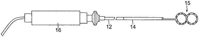
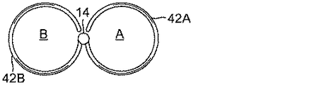
図1に示すように、カテーテル10は、細長いカテーテル本体12と、中間偏向区画14と、遠位区画15と、カテーテル本体12の近位端に取り付けられた偏向制御ハンドル16とを備える。本発明の特徴によれば、遠位区画15は、所定の2次元(2D)構成の形状記憶が付いた、少なくとも1つの可撓性管状部材を有し、展開されたとき、又はさもなければ可撓性管状遠位区画を概ね直線状にし得る外力(1つ又は複数)から放たれたときに、「無限大」記号又は「レイジーエイト」に似た少なくとも2つの横並びループを含む2D構成を取る。2つ又は3つ以上の横並びループの展開済み2D構成は、概ね同時的な様式にて、遠位区画15が、心門を含む2つ又は3つ以上の肺静脈(PV)領域に接触することを可能にしている。各ループには、電気データをPV領域から取得するかつ/又はそれを焼灼するための、1つ又は2つ以上の電極(例えば、先端電極17及び少なくとも1つの環電極19)が担持される。
As shown in FIG. 1, the catheter 10 includes an
図2A及び図2Bを参照すると、カテーテル本体12は、1個の軸方向又は中央管腔18を有する細長い管状構造を含む。カテーテル本体12は、可撓性、即ち屈曲可能であるが、その全長に沿って実質的に非圧縮性である。カテーテル本体12は、任意の適当な構造のものでよく、任意の適当な材料で作製することができる。現在好ましい構成体は、ポリウレタン又はPEBAXで作製された外壁20を含む。外壁20にはステンレス鋼などの編組メッシュが埋め込まれていることによってカテーテル本体12のねじれ剛性が高められているため、制御ハンドル16が回転させられると、カテーテル10の中間区画14がこれに応じて回転する。
With reference to FIGS. 2A and 2B, the
カテーテル本体12の外径は重要ではないが、好ましくは2.7mm(約8フレンチ)以下、より好ましくは2.3mm(約7フレンチ)である。同様に、外壁20の厚さもそれほど重要ではないが、外壁20は、中央管腔18が、牽引ワイヤー、1つ又は2つ以上のリードワイヤー、及び他の任意の所望されるワイヤー、ケーブル又はチューブを収容できるように、十分に薄い。所望される場合、外壁20の内面は、ねじれ安定性を向上させるために強化チューブ25で裏打ちされる。特に好ましいカテーテルは、外径が約0.23センチメートル〜約0.24センチメートル(約0.090インチ〜約0.94インチ)、かつ内径が約0.15センチメートル〜約0.17センチメートル(約0.061インチ〜約0.065インチ)の外壁20を有する。
The outer diameter of the
図2A、2B及び2Cに示すように、中間区画14は、複数の管腔、例えば、4つの管腔31、32、33及び34を有する管材22の短い区画を備えている。第1の管腔31には、更に後述する1つ又は2つ以上のリードワイヤー40又は他のワイヤーが担持され、第2の管腔32には、牽引ワイヤー24が担持され、その遠位端付近の第3の管腔33には、形状記憶付き支持部材38の近位端が担持される。第4の管腔34には、電磁式位置センサー30用のケーブル26が担持される。管材22は、好ましくはカテーテル本体12よりも可撓性に優れる、毒性のない好適な材料で作製される。編組ステンレス鋼などのメッシュが包埋された編組ポリウレタンは、管材22に好適な材料の1つである。各管腔のサイズは、重要ではないが、リードワイヤー、牽引ワイヤー又は支持部材を収容するうえでは十分である。
As shown in FIGS. 2A, 2B and 2C, the
カテーテルの有効長(即ち、遠位区画15を除いた、体内に挿入可能な部位)は、所望される場合、変更してもよい。好ましくは、有効長は、約110cm〜約120cmに及ぶ。中間区画14の長さは、有効長のうちの比較的小さな部位であり、好ましくは約3.5cm〜約10cm、より好ましくは約5cm〜約6.5cmに及ぶ。
The effective length of the catheter (ie, the site that can be inserted into the body, excluding the distal section 15) may be varied if desired. Preferably, the effective length ranges from about 110 cm to about 120 cm. The length of the
カテーテル本体12を中間区画14に取り付ける好ましい手段が、図2A及び2Bに示されている。中間区画14の近位端は、カテーテル本体12の内面を受容する外周ノッチ27を含む。中間区画14及びカテーテル本体12は、接着剤等により取り付けられる。
A preferred means of attaching the
所望される場合、スペーサ(図示せず)を、カテーテル本体内の、強化チューブ(提供される場合)の遠位端と中間区画の近位端との間に配置できる。スペーサは、カテーテル本体と中間区画との接合部で可撓性の変化をもたらし、これにより、接合部が折り畳まれる又はよじれることなく滑らかに曲がることが可能になる。このようなスペーサを有するカテーテルは、米国特許第5,964,757号に開示され、この開示は参考として本明細書に組み込まれる。 If desired, a spacer (not shown) can be placed in the catheter body between the distal end of the stiffening tube (if provided) and the proximal end of the intermediate section. The spacer provides a change in flexibility at the junction between the catheter body and the intermediate section, which allows the junction to bend smoothly without being folded or kinked. A catheter having such a spacer is disclosed in US Pat. No. 5,964,757, the disclosure of which is incorporated herein by reference.
図3A、3B及び3Cに示すように、中間区画14の遠位端から延在しているのが、遠位区画15である。遠位区画15の各可撓性の細長部材42は、形状記憶付きの細長い支持部材38と、その支持部材38を被覆する非導電性被覆物又は管材28とを備える。部材42の長さは、約20mm〜約300mm、より好ましくは約100mm〜約200mm、更により好ましくは約120mmの範囲であるが、所望される場合は変更してもよい。それぞれの部材42で形成される各ループは、直径又は幅が約4mm〜約40mm、より好ましくは約10mm〜約25mm、更により好ましくは約17mmの範囲であるが、所望される場合は変更してもよい。支持部材38は、形状記憶を有する材料(即ち、力を加えると、その本来の形状から離れて一時的に伸張させるか又は屈曲させることが可能であり、かつ力を取り除くと、実質的に本来の形状に戻ることが可能である材料)から作製される。ニッケル/チタン合金は、支持部材38の好適な材料の1つである。このような合金は、典型的には、約55%のニッケルと45%のチタンとを含むが、約54%〜約57%のニッケルと、チタンである残部を含んでもよい。ニッケル/チタン合金は、耐久性、強度、耐食性、電気抵抗、及び温度安定性と共に、優れた形状記憶性を有する、ニチノールである。非導電性被覆物28は、任意の好適な材料で作製することが可能であり、好ましくは、ポリウレタン又はPEBAXなどの生体適合性プラスチックから作製される。所望される場合、支持部材38は排除され得、非導電性被覆物28の遠位端は、所望される湾曲又は構成を有するように予備成形され得る。
Extending from the distal end of the
非導電性被覆物28は、中間区画14及び遠位区画15の接合部にて、中間区画の管材22に接着剤37などで取り付けられる。支持部材38は、第3の管腔33から非導電性被覆物28へと延在する。支持部材38の近位端は、管材22の遠位端からおよそ約5mmの、第3の管腔34(third lumen 34)の内側で終端するため、中間区画14の偏向する能力に悪影響が及ばずに済む。しかしながら、所望される場合、支持部材38の近位端は、カテーテル本体12内に延在させ得る。
The
図4A〜4Eを参照すると、(簡潔にするため、如何なる先端電極又は環電極も含めずに例示してある)遠位区画15は、所定の2D構成(図4E)の、略線形(一次元)の、但し支持部材38により提供される、形状記憶付きの可撓性管状部材42を備え、この2D構成は、少なくとも2つの横並びのループA及びBを含み、それらのループAとロープBとは、互いに概ね同一平面上にあり、かつ互いに最も近い場所Xにて概ね接合又は交差しており(又は接合若しくは交差する外観を有しており)、「無限大」記号又はレイジーエイト(本明細書において同義に用いられている記号)に類似する。当然のことながら、本明細書に使用するとき、用語「ループ」は、単一の連続した可撓性管状部材で達成される閉じた構成を必ずしも意味するとは限らず、むしろ、概ね閉じた構成のパターンの組織表面との接触を可能にして、それぞれの領域(例えば、それぞれのPV心門)を囲繞する又は取り囲む目的で、1つ又は2つ以上の可撓性管状部材を、ループに類似するか又はループの外観を有するように構成し得る。換言すれば、当然のことながら、用語「ループ」とは、領域(例えば、PV心門)をマッピング及び/又は焼灼する目的で、結果として得られる、組織表面上の1つ又は2つ以上の可撓性管状部材の「スタンプ」又は「押印」パターンに関して使用される。
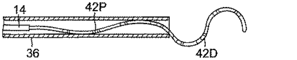
4A-4E, the distal section 15 (illustrated for simplicity, not including any tip or ring electrodes) is substantially linear (one-dimensional) in a predetermined 2D configuration (FIG. 4E). ), But with a shape memory
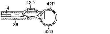
管状部材42は、遠位部分42Dと近位部分42Pとを備えて記述される得る。部材42は、可撓性構成体を備えるため、概ね直線状になり得ると共に、チューブ、例えば、ガイドシース36(図4A)を通して遠位に前進することも可能になっている。遠位部分42Dは、ガイドシース36の遠位端を通過し、その遠位端から出るため、遠位部分42Dは、遠位又は第1の「S」構成をその形状記憶下にあるものと想定する(図4B)。遠位区画15の部材42は引き続き展開されるため、部材42の形状記憶により、約180°に等しい角度θで、遠位部分42Dが近位部分42P(図4C)の上に折れ曲がるか又は反転する。近位部分42Pはガイドシース36の遠位端を通過してその遠位端から出るため、近位部分42Pは近位の又は第2の「S」構成をその形状記憶下にあるものと想定する(図4D及び4E)。遠位部分42D及び近位部分42Pの両方が完全に展開されている場合、第1及び第2の「S」構成では、一方が他方の上に積み重ねられ(図4F)、一方の「S」が他方に対して上下逆に配されており、その結果として、部材42が無限大記号に似た所定の2D構成を取ると、横並びの構成のループA及びループBが、事実上形成される(図4E)。ループA及びB(並びに、遠位部分42D及び近位部分42B)が、概ね共通の平面内に位置し、また、中立の状態にあるときに中間偏向区画14に占有されるか(図4F)、又は遠位区画15の2D構成の部材42が中間偏向区画14を介して角度αで偏向され、結果として、ループA及びB(並びに、遠位部分42D及び近位部分42B)がそれぞれ別々の平面内に位置するようになっている(図4G)。
別の実施形態においては、図11A〜11Dに示すように、遠位の「S」構成を形成する遠位部分42Dは、近位の「S」構成を形成する近位部分42Pを反転させることもないし、又その近位部分上に折り返させることもない。むしろ、遠位の「S」構成42Dの湾曲は、近位の「S」構成42Pの湾曲と連続していて、その2つが、遠位区画15が展開されるのと同じ平面内に概ね留まるようになっている。
In another embodiment, as shown in FIGS. 11A-11D, the
ループA及びBが達成される様式に関係なく、図5に示すように、遠位区画15の2D構成は、事実上、右心房RAから経中隔手法を介して肺静脈の左心房LA内の隣接した心門80A及び80Bの対の上に位置決めされる。ループAが心門80A上に位置決めされ、かつループBが心門80B上に位置決めされた状態で、第2のカテーテルを必要とすることなく、カテーテル10を使用しながら同時に、心門A及びBの領域内で電気信号の読み出しが可能である。カテーテル10が焼灼に適応されている場合、心門A及びBの領域がカテーテル10と同時に焼灼され得る。カテーテル10は、肺静脈心門82A及び82Bがマップ及び/又は焼灼されるように、再配置され得る。
Regardless of the manner in which loops A and B are achieved, as shown in FIG. 5, the 2D configuration of the
無限大記号に似た2D構成は、後述のものをはじめとする多種多様な構成体で達成することが可能である。図6A〜6Gにおいて、遠位区画15の部材42は、無限大記号に似た2D構成を達成するために別の形状記憶構成を有する。本実施形態において、部材42は、略閉ループ、即ち「O」構成を提供する遠位部分42D(図6A)と、遠位の「O」構成と概ね共通の平面内に延在している第1の近位の「C」構成を提供する第1の近位部分42P(図6A)とを有する。部位42Pはガイドシース36の外側に完全に展開されているため、部位42D及び42Pが、より近位の部位42P’(図6B)上へ約180°の角度θで折れ曲がり(部材42の形状記憶下に置かれ)、それにより、部位42Pのさほど近位でない「C」構成とは反対方向の第2の「C」構成が提供され、無限大記号に似た2D構成が達成される。部位42P’がガイドシース36の外側に完全に展開されると、2D構成が約90°の角度αで折れ曲がるか又は反転し(遠位区画15の形状記憶下に置かれ)、中間偏向区画14に概ね直交する(図6F)。当然のことながら、2D構成が中間偏向区画14から延在する角度は、所望されるように又は適宜に、任意の角度を取り得る。例えば、2D構成及び偏向区画14は、同じ共通の平面内に概ね位置し得る(図6G)。つまり、2D構成は、偏向区画14まで横断し、それより「T」構成を用いるが、偏向区画14とは異なる平面内に存在するか(図6F)、又は偏向区画と同じ平面内に存在し得る(図6G)。
A 2D configuration resembling an infinite symbol can be achieved with a wide variety of configurations, including those described below. 6A-6G, the
別の実施形態においては、図12A〜12Cに示すように、ループAを形成する遠位部分42Dが反転することも、又折り返すこともない。むしろ、近位部分42Pの構成42Dが湾曲するため、引き続きループBが形成される。図11A〜11D及び図12A〜12Dを実施形態を比較し対照すると、遠位区画15の展開中に両方の実施形態のループA及びBは、概ね同じ平面内に留まるが、それに対して、2D構成の近位端は、ループの外節又は弧に沿った場所にあってもよいし、又はループの内節又は弧に沿った場所にあってもよい(図12C)。
In another embodiment, as shown in FIGS. 12A-12C, the
図7Aは、遠位区画15が、一方向(例えば、時計回り)に第1のループ、即ち「O」構成(図6A)を提供する遠位部分15Dと、反対方向(例えば、反時計回り)に第2のループ、即ち「O」構成を提供する近位部分15Pとを有し、それら両方の区画は、中間偏向区画14と共通の平面内に概ね位置し、ループA及びBの共通の場所Xは、偏向区画14に対して長手方向に概ね整列配置される、別の実施形態を例示している。
FIG. 7A shows that the
図7Bは、遠位区画15が、一方向(例えば、反時計回り)に第1のループA、即ち「O」構成(図6A)を提供する遠位部分15Dと、同じ方向(例えば、反時計回り)に第2のループB、即ち「O」構成を提供する近位部分15Pとを有し、それら両方の区画は共通の平面内に概ね位置し、中間偏向区画14に概ね直交する、別の実施形態を例示している。その上、ループA及びBの共通の場所Xは、偏向区画14から長手方向にオフセットされる。
FIG. 7B shows that the
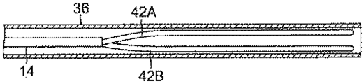
図8A〜8Eは、遠位区画15が、中間偏向区画14の遠位端から延在する少なくとも2つの概ね平行な細長い可撓性管状部材42A及び42Bを含む、更に別の実施形態を例示している。図10A及び10Bに示すように、各部材42A及び42Bは、それぞれの細長い形状記憶付き支持部材38A及び38B、並びにそれぞれの非伝導性被覆物、又は管材28A及び28Bを有する。部材42A及び42Bはそれぞれ、可撓性構成体を備えるため、概ね直線状になり得ると共に、チューブ、例えば、ガイドシース36(図8A)を通して遠位に前進することも可能になっている。部材42A及び42Bは、ガイドシース36の遠位端から出たときに完全に展開され(図8B)、部材42A及び42Bの各々は、その形状記憶により再帰的に湾曲し始め、ループ、即ち「O」構成を生じて、その近位端から外向きに反対方向へ旋回することにより、互いに分離する(図8D及び8E)。ループA及びBは、約180°の角度βで分離され、共通の平面内に概ね位置する無限大記号に概ね似た2D構成を形成し、偏向区画14は、遠位区画15の2D構成に概ね直交する(図8F)。繰り返しになるが、当然のことながら、中間偏向区画14と遠位区画15との間の接合部の構成に応じて、遠位区画15の2D構成及び偏向区画14は、必要又は要求に応じて、共通の平面内にある場合もあれば、互いに直交する場合もあれば、又は、事実上互いに任意の角度方向にある場合もある。
8A-8E illustrate yet another embodiment in which the
当然のことながら、遠位区画15の2D構成のループは、サイズ又は形状が互いに同じである必要はない。一方のループは、他方より小さくてもよい。一方のループは、より円形であってもよいし、他方(1つ又は複数)はより楕円形であってもよい。各ループは、完全閉ループを形成する必要はないが、少なくとも約270°、より好ましくは少なくとも約320°、より好ましくは少なくとも約340°でなければならない。各ループには、電気データをPV領域から取得し、かつ/又はそれを焼灼するための、1つ又は2つ以上の電極、例えば、少なくとも1つの環電極、及び所望される場合又は該当する場合は、先端電極が担持される。
Of course, the loops of the 2D configuration of the
遠位区画15の2D構成の任意の部材42に対する先端電極17は、部材42の遠位端上に取り付けられる。図7に示すように、先端電極17は、露出された遠位部分17Dと、非導電性被覆物28へと延在し、かつその被覆物の内部にポリウレタン接着剤などで固定される近位ステム17Pとを有する。
The
電極リードワイヤー40Tは、その遠位端にて先端電極17に接続される。リードワイヤー40Tの遠位端は、先端電極17の近位端にある第1の止まり孔51に半田付けされる。リードワイヤー40Tは、非導電性被覆物28と支持部材38との間に延在する。当該技術分野において公知であるように、リードワイヤー40Tの近位端は、制御ハンドル16の遠位端にある好適なコネクタ(図示せず)に電気的に接続され、このコネクタは、焼灼エネルギー、例えば、RFエネルギーの供給元に接続される。リードワイヤー40Tは、非伝導性被覆物28の管腔、中間区画14の第1の管腔31、カテーテル本体12の中央管腔18、及び制御ハンドル16を通って延在する。図示されている実施形態において、カテーテル本体12の中央管腔18、及び中間区画14の管腔31を通って延在しているリードワイヤー40Tの一部は、カテーテル内の他のコンポーネントとの接触を防ぐため、保護シース84の内部に封入され得る。保護シースは、任意の好適な材料、好ましくはポリイミドから作製され得る。保護シースの遠位端は、ポリウレタン接着剤などにより第1の管腔31内に接着することによって中間区画14の近位端に係留され得る。当業者に認識されるように、所望される場合、保護シースは排除してもよい。
The
所望される場合、焼灼前に焼灼対象領域をマッピングし、焼灼を実行し、かつ/又は焼灼した後に結果として生じた病変によって電気活動が確実に阻止されるようにするため、1つ又は2つ以上の環電極19が、遠位区画15の非導電性被覆物28上に取り付けられる。かかる環電極を含むカテーテルの説明は、「A Catheter Having Circular Ablation Assembly」と題された米国特許第8545495号に記載されており、その開示内容全体は、本明細書において参照により援用されている。
If desired, one or two to map the area to be ablated before ablation, perform ablation and / or ensure that electrical activity is blocked by the resulting lesion after ablation The
環電極19は、プラチナ又は金、好ましくはプラチナとイリジウムとの組み合わせなどの任意の好適な固体導電性材料で作製することが可能であり、接着剤などで非導電性カバー28上に取り付けることが可能である。あるいは、環電極19は、非導電性カバー28を、プラチナ、金、及び/又はイリジウムなどの導電性材料でコーティングすることによって形成することができる。コーティングは、スパッタリング、イオンビーム蒸着、又はこれに相当する技術を用いて施すことができる。
The
図3Bの実施形態において、各環電極19は、最初に非導電性カバー28内に穴62を形成することにより、取り付けられる。それぞれの電極リードワイヤー40Rは、孔62を通して送り込まれ、環電極19は、リードワイヤー40R及び非導電性カバー28上の定位置で溶接される。リードワイヤー40Rは、非導電性カバー28の管腔、中間偏向区画14の第1の管腔31、カテーテル本体12の中央管腔18を通って延在する。各リードワイヤー40Rの近位端は、制御ハンドル16内の好適なコネクタ(図示せず)電気的に接続される。
In the embodiment of FIG. 3B, each
所望される場合、遠位区画15上の環電極19の数を変更することもできる。環電極の数は、好ましくは約6〜約20、より好ましくは約8〜約12の範囲である。一実施形態において、遠位区画15には10個の環電極が担持される。環電極19は、遠位区画15に沿ってほぼ等しい間隔を置いて配置され得る。一実施形態において、隣接する環電極19の中心部間には、およそ5mmの距離が設けてある。
If desired, the number of
別の実施形態において、遠位区画15は、一連の環電極対を備える。各環電極対は、2つの近接する環電極を備える。本明細書で使用するとき、用語「環電極対」は、他の隣接する環電極に対してよりも、互いにより近くに配置される環電極対を指す。電極対の2個の電極の間の距離は、好ましくは約3mm未満、より好ましくは約2mm未満、更により好ましくは約0.5mm〜約1.5mmである。電極対の数は、所望される場合、変更してもよく、好ましくは6〜14対、より好ましくは10対の範囲である。
In another embodiment, the
遠位区画15には、各対の2つの電極間におよそ1mmの間隔を設けた10対の電極が担持され得る。好ましくは、各環電極が比較的短く、長さが約0.4mm〜約0.75mmの範囲であり、最も遠位の環電極が他方の環電極よりも長く、好ましくは長さが約1mm〜約1.5mmの範囲である。環電極が長いほど、カテーテルをX線透視下で見たとき、ユーザーが視覚的に確認しやすい。最遠位の環電極など1個の環電極を他の環電極とは異なる寸法に形成することにより、ユーザーは、カテーテルをX線透視下で見たときの基準点を有する。
The
環電極の寸法及び数にかかわらず、電極対は、好ましくは、遠位区画15に沿ってほぼ等しい間隔を置いて配置される。近接配置された電極対により、心房細動治療を試みる際に非常に重要である、遠距離場の心房信号に対する近距離場の肺静脈電位の検出の精度を向上できる。具体的には、近距離場の肺静脈電位は極めて小さい信号であり、一方で心房は、肺静脈に極めて近接する場所にあり、遙かに大きい信号を提供する。したがって、マッピングアレイが肺静脈の領域内に配置されている場合であっても、信号が(肺静脈からの)小さい近接する電位か、又は(心房からの)より大きいより遠方の電位のいずれであるかを医師が判定することは、困難であり得る。近接配置される双極子により、医師は、近接する信号又は遠方の信号のいずれを検査しているかを、より正確に判定することが可能になる。したがって、近接配置される電極を有することによって、肺動脈電位を有する心筋組織の場所を、正確に標的とすることが可能であるため、臨床医は、特定の組織に治療を施すことが可能になる。更には、近接配置される電極により、医師は電気信号によって心門(1つ又は複数)の正確な解剖学的場所を判定することが可能になる。
Regardless of the size and number of ring electrodes, the electrode pairs are preferably spaced approximately equally spaced along the
熱電対ワイヤー53及び54の対は、任意の先端電極17の温度を監視する目的で提供されている。任意の従来の温度センサー、例えば熱電対又はサーミスタが使用されてもよい。図7に示す実施形態において、熱電対は、エナメル付きワイヤー対により形成される。ワイヤー対のうちの一方のワイヤーは、銅線53、例えば、番手「40 AWG」の銅線である。ワイヤー対の他方のワイヤーは、コンスタンタン線54である。ワイヤー対のワイヤー53及び54は、その遠位端にて一体に撚り合わせられているが、それを除き、互いに電気的に絶縁され、プラスチック管材55、例えば、ポリイミドの短片で被覆され、かつエポキシで被覆されている。次いで、プラスチック管材55が、ポリウレタン接着剤などにより、先端電極17の第2の止まり孔56内に取り付けられる。あるいは、ワイヤー53及び54を第2の止まり孔56の中に半田付けしてもよいし、又はさもなければ先端電極17に取り付けてもよい。ワイヤー53及び54は、リードワイヤー40T及び40R(図2A)と共に、中間区画14内の第1の管腔31(図3C)を通り、カテーテル本体12の中央管腔18を通って延在する。次いで、ワイヤー53及び54は、制御ハンドル16を通って、温度モニター(図示せず)に接続可能なコネクタ(図示せず)へ延出する。
A pair of
加えて、先端電極17がカテーテルから取り外されることのないよう遠位区画15に更に固着するための、安全ワイヤー57が提供される。安全ワイヤーは、好ましくは金属ワイヤーであり、その遠位端は、先端電極17内の第3の止まり孔58に半田付けされていて、その近位端は、制御ハンドル16内に半田付けされているか又はさもなければ取り付けられている。図示されている実施形態において、安全ワイヤー57は、リードワイヤー40T及び40R、並びに熱電対ワイヤー53及び54と共に、中間区画14内の第1の管腔31(図3C)を通り、カテーテル本体12の中央管腔18(図2A)を通って延在している。当業者に認識されるように、安全ワイヤーを取り付けるための他の装置を提供してもよいし、又は安全ワイヤーを除去してもよい。
In addition, a
電磁式位置センサー30は、その遠位端(先端電極17からすぐ近位にある)に又はその付近にある非伝導性被覆物28の管腔内に収容される。センサーケーブル26は、センサー30から延出し、被覆物28の管腔(図3B)、偏向区画14の管材22の管腔34(図2C)、カテーテル本体12の管腔18(図2A)を通って、制御ハンドル16内に入る。
The
牽引ワイヤー24は、中間区画14が偏向されるように設けてある。牽引ワイヤー24は、カテーテル本体12を通って延在し、その近位端にて制御ハンドル16に係留され、その遠位端にて中間区画14の遠位端に係留される。牽引ワイヤー24は、ステンレス鋼又はニチノールのような任意の好適な金属で作製され、好ましくはTEFLONなどでコーティングされている。コーティングは、牽引ワイヤー24に潤滑性を付与する。牽引ワイヤー24の直径は、好ましくは約0.015〜約0.025センチメートル(約0.006〜約0.010インチ)の範囲である。
The pulling
図2Bに示すように、カテーテル本体12の内部には、牽引ワイヤー24に対して囲繞関係にある圧縮コイル66が位置している。圧縮コイル66は、カテーテル本体12の近位端から中間区画14の近位端まで延在している。圧縮コイル66は、任意の好適な金属、好ましくはステンレス鋼で作製される。圧縮コイル66は、可撓性(即ち、屈曲)をもたらすが圧縮には抵抗するように、緊密に巻き付けられている。圧縮コイル66の内径は、好ましくは、牽引ワイヤー24の直径よりもわずかに大きい。牽引ワイヤー24上のTeflonコーティングは、圧縮コイル66内を自由に摺動することを可能にしている。圧縮コイル66の外表面は、例えば、ポリイミド管材で形成された可撓性非導電性シース68で被覆されている。
As shown in FIG. 2B, a
圧縮コイル66は、その近位端にて、近位の接着剤接合部(図示せず)を介してカテーテル本体12外壁20に係留され、その遠位端にて、遠位の接着剤接合部72を介して中間区画14に係留される。どちらの接着剤接合部も、ポリウレタン接着剤などを含み得る。接着剤は、カテーテル本体12の外表面と中央管腔18との間に作製された穴を通じて、注射器などの手段によって塗布されてもよい。そのような穴は、例えば、カテーテル本体12の外壁20に穴を開ける、十分に加熱して恒久的な穴を形成する針などによって形成されてもよい。次いで、接着剤は、穴を通して圧縮コイル66の外表面に導入され、外側の周囲に毛管現象で広がって(wicks around)、圧縮コイルの全周囲の周りに接着剤接合部を形成する。
The
牽引ワイヤー24は、中間区画14の第2の管腔32へと延在する。図3に示すように、例示されている実施形態において、牽引ワイヤー24は、その遠位端にて、中間区画14の遠位端に係留されている。具体的には、管状ステンレス鋼80の小片(例えば皮下ストック)を含むT字型係留具が形成されており、この係留具は、牽引ワイヤー64(puller wire 64)の遠位端に嵌着され、牽引ワイヤーにしっかりと固着するために圧着されている。チューブ状のステンレス鋼80の遠位端は、ステンレス鋼のリボンなどで形成された十字片82に、例えば溶接によってしっかりと取り付けられている。十字片82は、第2の管腔32の遠位端を越えた位置にある。十字片82は、管腔開口部よりも大きいため、開口部から引っ張り出せない。次いで、第2の管腔32の遠位端は、接着剤又はその他同種のもの、好ましくはポリウレタン接着剤37で充填される。中間区画14の第2の管腔32内部では、牽引ワイヤー24がプラスチック、好ましくはTeflonの牽引ワイヤーのシース39を通って延在し、このシースは、偏向区画が偏向される際に、牽引ワイヤー24が偏向区画14の管材22の壁内に切れ込むのを防ぐ。
The
カテーテル本体12に対する牽引ワイヤー24の長手方向の動きは、中間区画14の撓みを引き起こし、この動きは、制御ハンドル16の好適な操作によって行われる。本発明で使用するための好適な制御ハンドルの例は、例えば、米国特許第Re 34,502号、及び同第5,897,529号に開示されており、その開示内容全体は本明細書において参照により援用されている。当然のことながら、双方向の偏向が所望される場合、偏向区画14内の(第1の牽引ワイヤー24用の管腔32とは概ね正反対の)管腔を通過する第2の牽引ワイヤーを提供し、かつ制御ハンドル16に感応するように、カテーテルを構成し得る。
Longitudinal movement of the
使用時には、図5に示すように、好適なガイドシース36が患者に挿入され、その遠位端が、所望されるマッピング場所及び/又は焼灼場所に位置決めされる。本発明と共に使用するのに好適なガイドシースの一例は、Biosense Webster,Inc.(Diamond Bar,Calif.)より市販されるPreface Braiding Guiding Sheathである。シースの遠位端は、右心房RA内に誘導された後に、経中隔手法で左心房LA内に誘導される。カテーテル10は、ガイドシース36を通過する。具体的には、カテーテルの遠位区画15がガイドシース36の近位端内に給送されると、遠位区画15の(1つ又は複数の)部材42は、シース36内に嵌入されるように直線状になる。カテーテルの遠位区画15が左心房LA内の所望される場所に位置決めされた後、ガイドシース36が近位方向に牽引され、必要に応じて、少なくとも遠位区画15は、偏向可能な中間区画14でない場合でも、露出される。ガイドシース36の外側では、遠位区画15が、その形状記憶下にて少なくともループA及びBを提供する2D構成を取る。次いで、ユーザーは、カテーテルを操作して、各ループがそれぞれの心門上に位置するように、遠位区画15の2D構成を位置決めする。遠位区画15が心門に接触している状態では、少なくとも2つの心門の領域内の電気活動は、第2のカテーテルを使用することなく、ループA及びB上の電極により同時に感知され得る。また、所望される場合、電極を通電することにより、第2のカテーテルを使用することなく、少なくとも2つの心門の領域内で、同時に焼灼できる。
In use, a
所望される場合、中間区画を操作する機能を高めるため、2つ又は3つ以上の牽引ワイヤーを提供してもよい。そのような実施形態において、第2の牽引ワイヤー及び囲繞する第2の圧縮コイルは、カテーテル本体を通って延在し、中間区画内の付加的な軸外管腔内に入る。2つ又は3つ以上の牽引ワイヤーを有するカテーテルの好適な設計(そのような実施形態に好適な制御ハンドルを含む)は、例えば、米国特許第6,123,699号、同第6,171,277号、同第6,183,435号、同第6,183,463号、同第6,198,974号、同第6,210,407号、及び同第6,267,746号に記載されており、その開示内容全体は本明細書において参照により援用されている。 If desired, two or more tow wires may be provided to enhance the ability to manipulate the intermediate compartment. In such embodiments, the second puller wire and the surrounding second compression coil extend through the catheter body and into an additional off-axis lumen in the intermediate compartment. Suitable designs of catheters having two or more puller wires (including control handles suitable for such embodiments) are described, for example, in US Pat. Nos. 6,123,699, 6,171, No. 277, No. 6,183,435, No. 6,183,463, No. 6,198,974, No. 6,210,407, and No. 6,267,746 The entire disclosure of which is hereby incorporated by reference.
上記の説明文は、現時点における本発明の好ましい実施形態に関連して提示されたものである。本発明が関係する分野及び技術における当業者であれば、本発明の原理、趣旨及び範囲を著しく逸脱することなく、説明された構造の改変及び変更が実施されてもよいを理解するであろう。当業者に理解されるように、図面は必ずしも一定の縮尺ではない。また、所望されるように、又は適切であれば、異なる実施形態の異なる特徴が組み合わされてもよい。更に、本明細書に記載されるカテーテルは、マイクロ波、レーザ、高周波、及び/又は寒剤などの、様々なエネルギーの形態に適用されるように、構成され得る。したがって、上記の説明は、説明され添付図面に示される厳密な構造のみに関係するものとして読み取るべきではなく、むしろ、最も完全で公正な範囲を有するであろう以下の「特許請求の範囲」と符合し、かつ「特許請求の範囲」を支持するものとして読み取るべきである。 The above description has been presented in connection with the presently preferred embodiments of the invention. Those skilled in the art to which the present invention pertains will appreciate that modifications and variations of the described structure may be made without departing significantly from the principles, spirit and scope of the present invention. . As will be appreciated by those skilled in the art, the drawings are not necessarily to scale. Also, different features of different embodiments may be combined as desired or appropriate. Further, the catheters described herein can be configured to be applied to various forms of energy, such as microwaves, lasers, radio frequency, and / or cryogens. Accordingly, the above description should not be read as referring only to the precise structure described and illustrated in the accompanying drawings, but rather has the following “claims” that will have the most complete and fair scope: And should be read as supporting the “claims”.
〔実施の態様〕
(1) カテーテルであって、
細長いカテーテル本体と、
少なくとも第1の形状記憶付き可撓性の細長部材を有する遠位区画であって、前記部材が、無限大記号に似た2D構成を取るように構成されている、遠位区画と、
前記部材の上に取り付けられている少なくとも1つの電極と、を備える、カテーテル。
(2) 前記2D構成が、第1のループ及び第2のループに類似し、前記第1のループと前記第2のループとが横並びになっており、共通の平面内に概ね延在する、実施態様1に記載のカテーテル。
(3) 前記第1の部材が、遠位のS構成と近位のS構成とを有し、前記S構成が互いに積み重ねられ、前記S構成のうちの一方が反転される、実施態様1に記載のカテーテル。
(4) 前記部材が、遠位のO構成と、第1の近位のC構成と、第2の近位のC構成とを有し、前記第1のC構成と第2のC構成とが互いに対向する、実施態様1に記載のカテーテル。
(5) 前記遠位区画に対して近位の偏向区画を更に含む、実施態様1に記載のカテーテル。
Embodiment
(1) a catheter,
An elongated catheter body;
A distal section having a flexible elongated member with at least a first shape memory, wherein the member is configured to assume a 2D configuration resembling an infinity symbol;
At least one electrode mounted on the member.
(2) The 2D configuration is similar to the first loop and the second loop, the first loop and the second loop are arranged side by side and extend generally in a common plane; The catheter according to embodiment 1.
(3) Embodiment 1 in which the first member has a distal S configuration and a proximal S configuration, the S configurations are stacked together, and one of the S configurations is inverted. The catheter described.
(4) the member has a distal O configuration, a first proximal C configuration, and a second proximal C configuration, the first C configuration and the second C configuration; The catheter of embodiment 1, wherein the are opposite to each other.
5. The catheter of embodiment 1, further comprising a deflection section proximal to the distal section.
(6) 前記2D構成及び前記偏向区画が、概ね、共通の平面内にある、実施態様5に記載のカテーテル。
(7) 前記2D構成と前記偏向とが互いに概ね直交する、実施態様5に記載のカテーテル。
(8) 前記2D構成が、第1のループと、第2のループと、前記第1のループと第2のループとの間の交点とを有する、実施態様5に記載のカテーテル。
(9) 前記交点が、前記偏向区画の長手方向軸と概ね整合されている、実施態様8に記載のカテーテル。
(10) 前記交点が、前記偏向区画の長手方向軸からオフセットされている、実施態様8に記載のカテーテル。
6. The catheter of embodiment 5, wherein the 2D configuration and the deflection section are generally in a common plane.
(7) The catheter of embodiment 5, wherein the 2D configuration and the deflection are substantially orthogonal to each other.
(8) The catheter of embodiment 5, wherein the 2D configuration comprises a first loop, a second loop, and an intersection between the first and second loops.
9. The catheter of
(10) The catheter of
(11) 第2の形状記憶付き可撓性の細長部材を更に含み、前記第1の細長部材が第1のループを形成するように構成され、前記第2の細長部材が第2のループを形成するように構成されており、前記第1のループと前記第2のループとが横並びになって交点を有する、実施態様1に記載のカテーテル。
(12) 前記第1のループ及び前記第2のループが、共通の平面内に概ね位置する、実施態様11に記載のカテーテル。
(13) カテーテルであって、
細長いカテーテル本体と、
少なくとも第1の形状記憶付き可撓性の細長部材を有する遠位区画であって、前記部材が、第1のループ及び第2のループを含む2D構成を取るように構成されており、前記第1のループ及び第2のループが、共通の平面内に概ね位置する、遠位区画と、
前記第1のループ及び前記第2のループの各々に設けられた少なくとも1つの電極と、を備える、カテーテル。
(14) 前記部材が、遠位のS構成と近位のS構成とを有し、前記S構成のうちの一方が他方のS構成に寄り掛かかって、前記第1のループ及び第2のループを含む前記2D構成を形成するように構成されている、実施態様13に記載のカテーテル。
(15) 前記部材が、遠位のC構成と、さほど近位でないO構成と、より近位のC構成とを有し、前記遠位のC構成及び前記近位のC構成が第1のループを形成し、前記近位のO構成が前記第2のループを形成する、実施態様13に記載のカテーテル。
(11) It further includes a flexible elongated member with a second shape memory, wherein the first elongated member is configured to form a first loop, and the second elongated member includes the second loop. The catheter of embodiment 1, wherein the catheter is configured to form and the first loop and the second loop are side by side and have an intersection.
12. The catheter of embodiment 11, wherein the first loop and the second loop are generally located in a common plane.
(13) a catheter,
An elongated catheter body;
A distal section having at least a flexible elongated member with shape memory, wherein the member is configured to take a 2D configuration including a first loop and a second loop; A distal section, wherein the one loop and the second loop are generally located in a common plane;
At least one electrode provided in each of the first loop and the second loop.
(14) The member has a distal S configuration and a proximal S configuration, one of the S configurations leaning on the other S configuration, and the first loop and the
(15) The member has a distal C configuration, a less proximal O configuration, and a more proximal C configuration, wherein the distal C configuration and the proximal C configuration are
(16) 前記部材が、前記第1のループ形成する遠位のO構成と、前記第2のループを形成する近位のO構成とを有する、実施態様13に記載のカテーテル。
16. The catheter of
Claims (16)
細長いカテーテル本体と、
少なくとも1つの形状記憶付き可撓性の細長部材を有する遠位区画であって、前記細長部材が、無限大記号に似た2D構成を取るように構成されており、自由端で終端している、遠位区画と、
前記細長部材の上に取り付けられている少なくとも1つの電極と、を備える、カテーテル。 A catheter,
An elongated catheter body;
A distal section having at least one flexible elongated member with shape memory, the elongated member being configured to take a 2D configuration resembling an infinity symbol , terminated at a free end A distal compartment;
At least one electrode mounted on the elongate member.
細長いカテーテル本体と、
少なくとも1つの形状記憶付き可撓性の細長部材を有する遠位区画であって、前記細長部材が、自由端で終端する2D構成を取るように構成されており、前記2D構成は、第1のループ及び第2のループを有し、前記第1のループ及び前記第2のループが、共通の平面内に概ね位置する、遠位区画と、
前記第1のループ及び前記第2のループの各々に設けられた少なくとも1つの電極と、を備える、カテーテル。 A catheter,
An elongated catheter body;
A distal section having at least one flexible elongate member with shape memory, wherein the elongate member is configured to take a 2D configuration terminating at a free end, the 2D configuration comprising: has a loop and a second loop, the first loop and the second loop is generally located in a common plane, and the distal section,
At least one electrode provided in each of the first loop and the second loop.
Applications Claiming Priority (2)
| Application Number | Priority Date | Filing Date | Title |
|---|---|---|---|
| US14/292,635 US9468407B2 (en) | 2014-05-30 | 2014-05-30 | Catheter with distal section having side-by-side loops |
| US14/292,635 | 2014-05-30 |
Publications (2)
| Publication Number | Publication Date |
|---|---|
| JP2015226769A JP2015226769A (en) | 2015-12-17 |
| JP6576695B2 true JP6576695B2 (en) | 2019-09-18 |
Family
ID=53269357
Family Applications (1)
| Application Number | Title | Priority Date | Filing Date |
|---|---|---|---|
| JP2015109580A Expired - Fee Related JP6576695B2 (en) | 2014-05-30 | 2015-05-29 | Catheter with side-by-side loops in the distal compartment |
Country Status (8)
| Country | Link |
|---|---|
| US (4) | US9468407B2 (en) |
| EP (1) | EP2949283B1 (en) |
| JP (1) | JP6576695B2 (en) |
| CN (2) | CN105266891B (en) |
| AU (1) | AU2015202458A1 (en) |
| CA (1) | CA2893154A1 (en) |
| IL (1) | IL238601A0 (en) |
| RU (1) | RU2015119230A (en) |
Families Citing this family (6)
| Publication number | Priority date | Publication date | Assignee | Title |
|---|---|---|---|---|
| JP2017505215A (en) * | 2014-02-07 | 2017-02-16 | ベルブ メディカル, インコーポレイテッド | Method and system for resection of a renal pelvis |
| US9468407B2 (en) * | 2014-05-30 | 2016-10-18 | Biosense Webster (Israel) Ltd. | Catheter with distal section having side-by-side loops |
| EP3589225B1 (en) | 2017-05-12 | 2021-11-17 | St. Jude Medical, Cardiology Division, Inc. | Electroporation systems and catheters for electroporation systems |
| EP3981348B1 (en) * | 2017-08-18 | 2024-02-14 | St. Jude Medical, Cardiology Division, Inc. | Medical catheters and systems including medical catheters |
| US11045658B2 (en) * | 2018-06-28 | 2021-06-29 | Medtronic, Inc. | Receive coil configurations for implantable medical device |
| CN111658134B (en) * | 2020-07-10 | 2021-09-21 | 四川锦江电子科技有限公司 | Cardiac pulse electric field ablation catheter |
Family Cites Families (31)
| Publication number | Priority date | Publication date | Assignee | Title |
|---|---|---|---|---|
| US3866615A (en) * | 1973-01-15 | 1975-02-18 | Daigle Claude W | Portable electronic cardiac stimulator |
| US4960134A (en) | 1988-11-18 | 1990-10-02 | Webster Wilton W Jr | Steerable catheter |
| US5282845A (en) * | 1990-10-01 | 1994-02-01 | Ventritex, Inc. | Multiple electrode deployable lead |
| US6161543A (en) | 1993-02-22 | 2000-12-19 | Epicor, Inc. | Methods of epicardial ablation for creating a lesion around the pulmonary veins |
| ATE320282T1 (en) * | 1993-10-14 | 2006-04-15 | Boston Scient Ltd | ELECTRODES FOR GENERATING CERTAIN PATTERNS OF PATHOLOGICALLY ALTERED TISSUE |
| EP0861676B1 (en) * | 1993-11-10 | 2003-10-01 | Medtronic Cardiorhythm | Electrode array catheter |
| US5454370A (en) * | 1993-12-03 | 1995-10-03 | Avitall; Boaz | Mapping and ablation electrode configuration |
| US5897529A (en) | 1997-09-05 | 1999-04-27 | Cordis Webster, Inc. | Steerable deflectable catheter having improved flexibility |
| US5964757A (en) | 1997-09-05 | 1999-10-12 | Cordis Webster, Inc. | Steerable direct myocardial revascularization catheter |
| US6123699A (en) | 1997-09-05 | 2000-09-26 | Cordis Webster, Inc. | Omni-directional steerable catheter |
| US6171277B1 (en) | 1997-12-01 | 2001-01-09 | Cordis Webster, Inc. | Bi-directional control handle for steerable catheter |
| US6183463B1 (en) | 1997-12-01 | 2001-02-06 | Cordis Webster, Inc. | Bidirectional steerable cathether with bidirectional control handle |
| US6198974B1 (en) | 1998-08-14 | 2001-03-06 | Cordis Webster, Inc. | Bi-directional steerable catheter |
| US6210407B1 (en) | 1998-12-03 | 2001-04-03 | Cordis Webster, Inc. | Bi-directional electrode catheter |
| US6267746B1 (en) | 1999-03-22 | 2001-07-31 | Biosense Webster, Inc. | Multi-directional steerable catheters and control handles |
| US6183435B1 (en) | 1999-03-22 | 2001-02-06 | Cordis Webster, Inc. | Multi-directional steerable catheters and control handles |
| WO2001019270A1 (en) | 1999-09-15 | 2001-03-22 | The General Hospital Corporation Doing Business As Massachusetts General Hospital | Coiled ablation catheter system |
| US6972016B2 (en) | 2001-05-01 | 2005-12-06 | Cardima, Inc. | Helically shaped electrophysiology catheter |
| US6771996B2 (en) | 2001-05-24 | 2004-08-03 | Cardiac Pacemakers, Inc. | Ablation and high-resolution mapping catheter system for pulmonary vein foci elimination |
| US6733499B2 (en) | 2002-02-28 | 2004-05-11 | Biosense Webster, Inc. | Catheter having circular ablation assembly |
| AUPS226402A0 (en) | 2002-05-13 | 2002-06-13 | Advanced Metal Coatings Pty Limited | An ablation catheter |
| US6973339B2 (en) | 2003-07-29 | 2005-12-06 | Biosense, Inc | Lasso for pulmonary vein mapping and ablation |
| US7366557B2 (en) * | 2003-11-07 | 2008-04-29 | Biosense Webster, Inc. | Flower catheter |
| US20050228468A1 (en) | 2004-04-01 | 2005-10-13 | Macoviak John A | Devices, systems, and methods for treating atrial fibrillation |
| US7419486B2 (en) * | 2005-06-15 | 2008-09-02 | St. Jude Medical, Atrial Fibrillation Division, Inc. | Treatment and diagnostic catheters with hydrogel electrodes |
| EP2001383A4 (en) | 2006-03-17 | 2011-01-19 | Microcube Llc | Devices and methods for creating continuous lesions |
| CN103142305A (en) | 2012-10-31 | 2013-06-12 | 中美联合技术(北京)有限公司 | Medical bipolar operation electrode with platy contacts |
| US9050010B2 (en) * | 2012-12-31 | 2015-06-09 | Biosense Webster (Israel) Ltd. | Double loop lasso with single puller wire for bi-directional actuation |
| US20140276755A1 (en) * | 2013-03-12 | 2014-09-18 | Boston Scientific Scimed, Inc. | Medical systems and methods for modulating nerves |
| US10105073B2 (en) * | 2013-11-21 | 2018-10-23 | Biosense Webster (Israel) Ltd | Flexible multiple-arm diagnostic catheter |
| US9468407B2 (en) * | 2014-05-30 | 2016-10-18 | Biosense Webster (Israel) Ltd. | Catheter with distal section having side-by-side loops |
-
2014
- 2014-05-30 US US14/292,635 patent/US9468407B2/en active Active
-
2015
- 2015-05-03 IL IL238601A patent/IL238601A0/en active IP Right Grant
- 2015-05-07 AU AU2015202458A patent/AU2015202458A1/en not_active Abandoned
- 2015-05-21 RU RU2015119230A patent/RU2015119230A/en not_active Application Discontinuation
- 2015-05-28 CA CA2893154A patent/CA2893154A1/en not_active Abandoned
- 2015-05-29 JP JP2015109580A patent/JP6576695B2/en not_active Expired - Fee Related
- 2015-05-29 CN CN201510288189.3A patent/CN105266891B/en not_active Expired - Fee Related
- 2015-05-29 EP EP15169910.5A patent/EP2949283B1/en active Active
- 2015-05-29 CN CN201910993995.9A patent/CN111134834A/en not_active Withdrawn
-
2016
- 2016-10-17 US US15/295,974 patent/US9788894B2/en not_active Expired - Fee Related
-
2017
- 2017-10-16 US US15/785,382 patent/US10143518B2/en not_active Expired - Fee Related
-
2018
- 2018-12-03 US US16/208,511 patent/US20190133680A1/en not_active Abandoned
Also Published As
| Publication number | Publication date |
|---|---|
| RU2015119230A3 (en) | 2018-12-14 |
| CN105266891B (en) | 2019-11-19 |
| CA2893154A1 (en) | 2015-11-30 |
| US20190133680A1 (en) | 2019-05-09 |
| CN105266891A (en) | 2016-01-27 |
| US10143518B2 (en) | 2018-12-04 |
| IL238601A0 (en) | 2015-11-30 |
| EP2949283B1 (en) | 2020-04-08 |
| JP2015226769A (en) | 2015-12-17 |
| CN111134834A (en) | 2020-05-12 |
| EP2949283A1 (en) | 2015-12-02 |
| US20180036079A1 (en) | 2018-02-08 |
| AU2015202458A1 (en) | 2015-12-17 |
| US9468407B2 (en) | 2016-10-18 |
| RU2015119230A (en) | 2016-12-10 |
| US20170035500A1 (en) | 2017-02-09 |
| US20150342531A1 (en) | 2015-12-03 |
| US9788894B2 (en) | 2017-10-17 |
Similar Documents
| Publication | Publication Date | Title |
|---|---|---|
| US12097034B2 (en) | Catheter with stacked spine electrode assembly | |
| US11116436B2 (en) | Catheter having closed electrode assembly with spines of uniform length | |
| US11083400B2 (en) | Catheter with high density electrode spine array | |
| JP6776021B2 (en) | Catheter with closed loop array with in-plane linear electrode portion | |
| JP6576695B2 (en) | Catheter with side-by-side loops in the distal compartment | |
| JP2016097307A (en) | Catheter with soft distal tip for mapping and ablating tubular region |
Legal Events
| Date | Code | Title | Description |
|---|---|---|---|
| A621 | Written request for application examination |
Free format text: JAPANESE INTERMEDIATE CODE: A621 Effective date: 20180529 |
|
| A977 | Report on retrieval |
Free format text: JAPANESE INTERMEDIATE CODE: A971007 Effective date: 20190318 |
|
| A131 | Notification of reasons for refusal |
Free format text: JAPANESE INTERMEDIATE CODE: A131 Effective date: 20190326 |
|
| A521 | Request for written amendment filed |
Free format text: JAPANESE INTERMEDIATE CODE: A523 Effective date: 20190625 |
|
| TRDD | Decision of grant or rejection written | ||
| A01 | Written decision to grant a patent or to grant a registration (utility model) |
Free format text: JAPANESE INTERMEDIATE CODE: A01 Effective date: 20190806 |
|
| A61 | First payment of annual fees (during grant procedure) |
Free format text: JAPANESE INTERMEDIATE CODE: A61 Effective date: 20190821 |
|
| R150 | Certificate of patent or registration of utility model |
Ref document number: 6576695 Country of ref document: JP Free format text: JAPANESE INTERMEDIATE CODE: R150 |
|
| LAPS | Cancellation because of no payment of annual fees |