JP6576098B2 - Medical camera device - Google Patents

Medical camera device Download PDF

Info

Publication number
JP6576098B2
JP6576098B2 JP2015104596A JP2015104596A JP6576098B2 JP 6576098 B2 JP6576098 B2 JP 6576098B2 JP 2015104596 A JP2015104596 A JP 2015104596A JP 2015104596 A JP2015104596 A JP 2015104596A JP 6576098 B2 JP6576098 B2 JP 6576098B2
Authority
JP
Japan
Prior art keywords
housing
casing
peripheral surface
outer peripheral
annular
Prior art date
Legal status (The legal status is an assumption and is not a legal conclusion. Google has not performed a legal analysis and makes no representation as to the accuracy of the status listed.)
Active
Application number
JP2015104596A
Other languages
Japanese (ja)
Other versions
JP2016214661A (en
Inventor
高太郎 天野
高太郎 天野
Current Assignee (The listed assignees may be inaccurate. Google has not performed a legal analysis and makes no representation or warranty as to the accuracy of the list.)
Sony Olympus Medical Solutions Inc
Original Assignee
Sony Olympus Medical Solutions Inc
Priority date (The priority date is an assumption and is not a legal conclusion. Google has not performed a legal analysis and makes no representation as to the accuracy of the date listed.)
Filing date
Publication date
Application filed by Sony Olympus Medical Solutions Inc filed Critical Sony Olympus Medical Solutions Inc
Priority to JP2015104596A priority Critical patent/JP6576098B2/en
Publication of JP2016214661A publication Critical patent/JP2016214661A/en
Application granted granted Critical
Publication of JP6576098B2 publication Critical patent/JP6576098B2/en
Active legal-status Critical Current
Anticipated expiration legal-status Critical

Links

Images

Description

本開示は、医療用カメラ装置に関する。   The present disclosure relates to a medical camera device.

従来、医療分野において、観察対象を観察するために、内視鏡装置等のカメラ装置が利用されている。このようなカメラ装置において、装置の使用目的や機能等を示す各種情報を識別するために、識別用の部材を観察装置に配置する技術が提案されている。   Conventionally, in the medical field, a camera device such as an endoscope device has been used to observe an observation target. In such a camera device, a technique has been proposed in which an identification member is arranged on an observation device in order to identify various types of information indicating the purpose and function of the device.

例えば、特許文献1には、内視鏡装置の筐体の外面に識別用のリングを嵌合して配置する技術が開示されている。   For example, Patent Document 1 discloses a technique in which an identification ring is fitted and arranged on the outer surface of a casing of an endoscope apparatus.

また、例えば、特許文献2には、内視鏡と制御装置とを連結するケーブルの制御装置と接続されるプラグに識別用の部材を配置する技術が開示されている。   Further, for example, Patent Document 2 discloses a technique in which an identification member is arranged on a plug connected to a cable control device that connects an endoscope and a control device.

特開2012−130367号公報JP 2012-130367 A 特開2005−168769号公報JP 2005-168769 A

ところで、このようなカメラ装置において、例えば硬性内視鏡に接続される内視鏡カメラヘッド等、内蔵された撮像素子により観察対象を撮像する医療用カメラヘッド(以下、単にカメラヘッドとも呼ぶ。)が用いられている。カメラヘッドは撮像によって得られた画像信号を、接続された例えばケーブル等の信号伝送部を介して他の機器へ出力する。そして、カメラ装置により得られた観察対象の画像は記録されたり、又は手術中に複数人で画像を観察するために表示装置に表示される。また、カメラヘッドは、観察する観察対象における位置を移動させるためにカメラヘッドを動かし、又はカメラヘッドの各種操作を行うためにカメラヘッドに設けられたスイッチを押下する目的で、ユーザにより把持された状態で使用される。   By the way, in such a camera device, for example, a medical camera head (hereinafter, also simply referred to as a camera head) that images an observation target with a built-in imaging device such as an endoscope camera head connected to a rigid endoscope. Is used. The camera head outputs an image signal obtained by imaging to another device via a connected signal transmission unit such as a cable. Then, an image to be observed obtained by the camera device is recorded or displayed on a display device so that a plurality of people can observe the image during surgery. In addition, the camera head is held by the user for the purpose of moving the camera head to move the position in the observation target to be observed or pressing a switch provided on the camera head to perform various operations of the camera head. Used in state.

しかしながら、カメラヘッドの場合は、ユーザにより把持されるため、カメラ装置に関する既存の技術を適用すると、識別用の部材を配置することによって、外部に露出し把持される部分に不要な凸部を形成させる場合があった。例えば、カメラヘッドの外観端部に識別用の部材を配置することによって、不要な凸部を形成させることなく、識別性が向上されることが期待される。当該箇所は、例えば信号伝送部等の電子部品を被覆する部材が接続される等、水密性や気密性が要求される箇所である場合がある。特に医療用のカメラ装置は、オートクレーブ滅菌や薬液での滅菌を行うため、液体にさらされる。しかし、特許文献1及び特許文献2に開示されている技術では、筐体の外周部に識別用の部材が配置されるため、水密性や気密性が要求される箇所に、当該箇所の水密性を確保しつつ、識別用の環状部材を配置することが困難である。   However, in the case of a camera head, since it is gripped by the user, if an existing technology related to the camera device is applied, an unnecessary protrusion is formed on the portion that is exposed to the outside and is gripped by arranging a member for identification. There was a case of letting. For example, by arranging a member for identification at the outer end of the camera head, it is expected that the identification performance is improved without forming unnecessary convex portions. The location may be a location where watertightness or airtightness is required, for example, a member that covers an electronic component such as a signal transmission unit is connected. In particular, medical camera devices are exposed to liquids for autoclave sterilization and chemical sterilization. However, in the techniques disclosed in Patent Document 1 and Patent Document 2, since a member for identification is arranged on the outer peripheral portion of the casing, the watertightness of the part is required at a place where watertightness or airtightness is required. It is difficult to arrange an annular member for identification while ensuring the above.

そこで、本開示では、識別性を損なうことなく、新規かつ改良された医療用カメラ装置を提案する。   Therefore, the present disclosure proposes a new and improved medical camera device without impairing discrimination.

本開示によれば、撮像素子を収納する第1の筐体を備えるカメラヘッドと、前記カメラヘッドと接続され少なくとも前記撮像素子からの画像信号を伝送するケーブル部と、前記ケーブル部が挿通される筒状の第2の筐体と、を備える信号伝送部と、前記第1の筐体と前記第2の筐体とで挟持され、前記カメラヘッドの種類を識別する外周面を有する環状部材と、前記第1の筐体と前記第2の筐体と前記環状部材とにより固定される環状のシール部材と、を備える医療用カメラ装置が提供される。   According to the present disclosure, a camera head including a first housing that houses an image sensor, a cable unit that is connected to the camera head and transmits at least an image signal from the image sensor, and the cable unit are inserted. A signal transmission unit comprising a cylindrical second housing, an annular member sandwiched between the first housing and the second housing and having an outer peripheral surface for identifying the type of the camera head; There is provided a medical camera device comprising: an annular seal member fixed by the first housing, the second housing, and the annular member.

以上説明したように本開示によれば、識別性を損なうことなく、新規かつ改良された医療用カメラ装置を提案することが可能である。   As described above, according to the present disclosure, it is possible to propose a new and improved medical camera device without impairing discrimination.

なお、上記の効果は必ずしも限定的なものではなく、上記の効果とともに、又は上記の効果に代えて、本明細書に示されたいずれかの効果又は本明細書から把握され得る他の効果が奏されてもよい。   Note that the above-mentioned effects are not necessarily limited, and any of the effects shown in this specification or other effects that can be grasped from this specification are provided together with or in place of the above-described effects. It may be played.

本開示の実施形態に係る内視鏡装置の一例の概略構成を示す説明図である。It is explanatory drawing which shows schematic structure of an example of the endoscope apparatus which concerns on embodiment of this indication. 本開示の実施形態に係るカメラヘッドの周辺の一例の概略構成を示す断面図である。It is sectional drawing which shows schematic structure of an example of the periphery of the camera head which concerns on embodiment of this indication. 図2に示したスイッチの周辺の拡大図である。FIG. 3 is an enlarged view of the periphery of the switch shown in FIG. 2. 図2に示した第1のシール部材及び第1のシール部材の周囲の構成を含む領域の拡大図である。FIG. 3 is an enlarged view of a region including a first seal member and a configuration around the first seal member illustrated in FIG. 2. 第2の筐体部の構成の一例を示す説明図である。It is explanatory drawing which shows an example of a structure of a 2nd housing | casing part. 第1の筐体部と第2の筐体部との接続方向に垂直な断面におけるカメラヘッドの断面図である。It is sectional drawing of the camera head in a cross section perpendicular | vertical to the connection direction of a 1st housing | casing part and a 2nd housing | casing part. 本開示の実施形態に係るカメラヘッドの周辺の一例の概略構成を示す分解斜視図である。It is a disassembled perspective view which shows schematic structure of an example of the periphery of the camera head which concerns on embodiment of this indication. 第1の変形例に係る第1のシール部材及び第1のシール部材の周囲の構成を含む領域の拡大図である。It is an enlarged view of the area | region containing the surroundings of the 1st sealing member which concerns on a 1st modification, and a 1st sealing member. 第2の変形例に係る第1のシール部材及び第1のシール部材の周囲の構成を含む領域の拡大図である。It is an enlarged view of the area | region containing the structure around the 1st sealing member which concerns on a 2nd modification, and a 1st sealing member. 第3の変形例に係る第1のシール部材及び第1のシール部材の周囲の構成を含む領域の拡大図である。It is an enlarged view of the area | region containing the structure around the 1st sealing member which concerns on a 3rd modification, and a 1st sealing member.

以下に添付図面を参照しながら、本開示の好適な実施の形態について詳細に説明する。なお、本明細書及び図面において、実質的に同一の機能構成を有する構成要素については、同一の符号を付することにより重複説明を省略する。   Hereinafter, preferred embodiments of the present disclosure will be described in detail with reference to the accompanying drawings. In addition, in this specification and drawing, about the component which has the substantially same function structure, duplication description is abbreviate | omitted by attaching | subjecting the same code | symbol.

なお、説明は以下の順序で行うものとする。
1.本開示の実施形態に係る内視鏡装置
2.本開示の実施形態に係るカメラヘッドの周辺の構成
2−1.カメラヘッドの周辺の概略構成
2−2.第1のシール部材の周囲の構成
3.変形例
3−1.第1の変形例
3−2.第2の変形例
3−3.第3の変形例
4.効果
5.むすび
The description will be made in the following order.
1. 1. Endoscope apparatus according to an embodiment of the present disclosure 2. Configuration around the camera head according to the embodiment of the present disclosure 2-1. Schematic configuration around the camera head 2-2. 2. Configuration around the first seal member Modification 3-1. First Modification 3-2. Second Modification 3-3. Third modification 4. Effect 5. Conclusion

<1.本開示の実施形態に係る内視鏡装置>
まず、図1を参照して、本開示の実施形態に係る内視鏡装置1の概略構成について説明する。
<1. Endoscopic apparatus according to an embodiment of the present disclosure>
First, a schematic configuration of an endoscope apparatus 1 according to an embodiment of the present disclosure will be described with reference to FIG.

図1は、本開示の実施形態に係る内視鏡装置1の一例の概略構成を示す説明図である。内視鏡装置1は、本開示に係る医療用カメラ装置の一例である。内視鏡装置1は、図1に示すように、挿入部10と、光源装置20と、ライトガイド30と、カメラヘッド40と、ケーブル50と、制御装置60と、表示装置70と、を備える。   FIG. 1 is an explanatory diagram illustrating a schematic configuration of an example of an endoscope apparatus 1 according to an embodiment of the present disclosure. The endoscope apparatus 1 is an example of a medical camera apparatus according to the present disclosure. As shown in FIG. 1, the endoscope apparatus 1 includes an insertion unit 10, a light source device 20, a light guide 30, a camera head 40, a cable 50, a control device 60, and a display device 70. .

挿入部10は、細長形状を有し、入射光を集光する光学系を内部に備える。挿入部10の先端は、例えば、患者の体腔内に挿入される。挿入部10の後端はカメラヘッド40の先端と着脱可能に接続される。また、挿入部10は、ライトガイド30を介して光源装置20と接続され、光源装置20から光を供給される。   The insertion unit 10 has an elongated shape and includes an optical system that collects incident light. The distal end of the insertion unit 10 is inserted into a patient's body cavity, for example. The rear end of the insertion unit 10 is detachably connected to the front end of the camera head 40. The insertion unit 10 is connected to the light source device 20 through the light guide 30 and is supplied with light from the light source device 20.

光源装置20は、ライトガイド30を介して挿入部10と接続される。光源装置20は、ライトガイド30を介して挿入部10に光を供給する。挿入部10に供給された光は、挿入部10の先端から出射され、患者の体腔内組織等の観察対象に照射される。そして、観察対象からの反射光は、挿入部10内の光学系によって集光される。   The light source device 20 is connected to the insertion unit 10 via the light guide 30. The light source device 20 supplies light to the insertion unit 10 via the light guide 30. The light supplied to the insertion unit 10 is emitted from the distal end of the insertion unit 10 and irradiated to an observation target such as a tissue in a body cavity of a patient. Then, the reflected light from the observation target is collected by the optical system in the insertion unit 10.

カメラヘッド40は、観察対象を撮像する機能を有する。カメラヘッド40は、信号伝送部であるケーブル50を介して制御装置60と接続される。カメラヘッド40は、挿入部10によって集光された観察対象からの反射光を光電変換することにより観察対象を撮像し、撮像によって得られた画像信号を制御装置60へケーブル50を介して出力する。なお、カメラヘッド40の詳細については、後述する。   The camera head 40 has a function of imaging an observation target. The camera head 40 is connected to the control device 60 via a cable 50 that is a signal transmission unit. The camera head 40 images the observation object by photoelectrically converting the reflected light from the observation object collected by the insertion unit 10, and outputs an image signal obtained by the imaging to the control device 60 via the cable 50. . Details of the camera head 40 will be described later.

制御装置60は、カメラヘッド40を制御するとともに、カメラヘッド40から出力された画像信号に所定の処理を施した後に、当該画像信号を表示装置70へ出力する。なお、制御装置60は、画像信号に基づく観察対象の画像を記憶してもよい。   The control device 60 controls the camera head 40, performs predetermined processing on the image signal output from the camera head 40, and then outputs the image signal to the display device 70. Note that the control device 60 may store an image to be observed based on the image signal.

表示装置70は、制御装置60から出力された画像信号に基づいて観察対象の画像を表示する。当該機能は、例えば、CRT(Cathode Ray Tube)ディスプレイ装置、液晶ディスプレイ(LCD)装置、又は有機ELディスプレイ(Organic Light Emitting Diode)装置により実現される。表示装置70により表示される観察対象の画像は、例えば、手術中に複数人によって観察される。   The display device 70 displays an image to be observed based on the image signal output from the control device 60. The function is realized by, for example, a CRT (Cathode Ray Tube) display device, a liquid crystal display (LCD) device, or an organic EL display (Organic Light Emitting Diode) device. The image of the observation target displayed by the display device 70 is observed by a plurality of people during the operation, for example.

<2.本開示の実施形態に係るカメラヘッドの周辺の構成>
(2−1.カメラヘッドの周辺の概略構成)
続いて、図2を参照して、本開示の実施形態に係るカメラヘッド40の周辺の概略構成について説明する。
<2. Configuration around Camera Head According to Embodiment of Present Disclosure>
(2-1. Schematic configuration around camera head)
Next, a schematic configuration around the camera head 40 according to the embodiment of the present disclosure will be described with reference to FIG.

図2は、本開示の実施形態に係るカメラヘッド40の周辺の一例の概略構成を示す断面図である。図2に示したように、カメラヘッド40は、カプラ部110と、第1の筐体部130と、レンズユニット150と、撮像基板である主基板170と、コネクタ接続基板190と、スイッチ接続基板210と、を備える。   FIG. 2 is a cross-sectional view illustrating a schematic configuration of an example of the periphery of the camera head 40 according to the embodiment of the present disclosure. As shown in FIG. 2, the camera head 40 includes a coupler unit 110, a first housing unit 130, a lens unit 150, a main board 170 that is an imaging board, a connector connection board 190, and a switch connection board. 210.

カプラ部110は、カメラヘッド40の先端に設けられ、挿入部10と着脱可能に接続される。カプラ部110の後端には、第1の筐体部130が設けられる。   The coupler unit 110 is provided at the tip of the camera head 40 and is detachably connected to the insertion unit 10. A first housing part 130 is provided at the rear end of the coupler part 110.

第1の筐体部130は、前側筐体131と、後側筐体133と、前側筐体131の外周面に設けられたスイッチ135と、後側筐体133の後端に設けられたコネクタ137と、を含む。第1の筐体部130は、レンズユニット150、主基板170、コネクタ接続基板190、及びスイッチ接続基板210を気密に収容する。これにより、第1の筐体部130の内部に外部からの湿気等の異物が侵入することを防ぐ。   The first housing unit 130 includes a front housing 131, a rear housing 133, a switch 135 provided on the outer peripheral surface of the front housing 131, and a connector provided at the rear end of the rear housing 133. 137. The first casing 130 accommodates the lens unit 150, the main board 170, the connector connection board 190, and the switch connection board 210 in an airtight manner. This prevents foreign matter such as moisture from entering the inside of the first housing part 130.

前側筐体131及び後側筐体133は、略円筒形状を有する例えばチタンやチタン合金やSUSの金属製の筐体であり、例えば溶接により接合されている。前側筐体131の外周面は、本開示に係る第1の外周面の一例であり、後側筐体133のうち前側筐体131と接続されるフランジ部を除く部分の外周面は、第1の外周面より断面外形が小さい本開示に係る第2の外周面の一例である。環状部材250、第1のシール部材270及び第2の筐体部230の少なくとも先端部は、当該第2の外周面を挿通し配設される。   The front housing 131 and the rear housing 133 are, for example, titanium, titanium alloy, or SUS metal housings having a substantially cylindrical shape, and are joined by welding, for example. The outer peripheral surface of the front housing 131 is an example of the first outer peripheral surface according to the present disclosure, and the outer peripheral surface of the portion of the rear housing 133 excluding the flange portion connected to the front housing 131 is the first outer surface. It is an example of the 2nd outer peripheral surface which concerns on this indication whose cross-sectional external shape is smaller than outer peripheral surface of this. At least the distal end portions of the annular member 250, the first seal member 270, and the second housing portion 230 are disposed through the second outer peripheral surface.

当該第1の外周面と当該第2の外周面との段差部には、後側筐体133側から、環状部材250及び環状部材250の内周部に嵌合される第1のシール部材270を介してケーブル50の一部である第2の筐体部230が接続される。当該第1の外周面と当該第2の外周面との段差部と、第2の筐体部230と、により環状部材250が挟持される。従って、後側筐体133の外面は、環状部材250、第1のシール部材270、及び第2の筐体部230により覆われる。このような前側筐体131及び後側筐体133によって、レンズユニット150、主基板170、コネクタ接続基板190、及びスイッチ接続基板210が覆われている。なお、前側筐体131及び後側筐体133の詳細については、後述する。   The first seal member 270 fitted to the inner peripheral portion of the annular member 250 and the annular member 250 from the rear housing 133 side at the step portion between the first outer peripheral surface and the second outer peripheral surface. The second casing 230, which is a part of the cable 50, is connected via the cable. The annular member 250 is sandwiched between the step portion between the first outer peripheral surface and the second outer peripheral surface and the second housing portion 230. Accordingly, the outer surface of the rear casing 133 is covered with the annular member 250, the first seal member 270, and the second casing portion 230. The lens unit 150, the main board 170, the connector connection board 190, and the switch connection board 210 are covered with the front housing 131 and the rear housing 133. Details of the front housing 131 and the rear housing 133 will be described later.

スイッチ135は、前側筐体131の外周面に設けられ、スイッチ接続基板210を介して撮像素子実装部171と接続される。スイッチ135は、例えば、1又は複数設けられ、ユーザは、スイッチ135を押下することによって、各種操作を行うことができる。   The switch 135 is provided on the outer peripheral surface of the front housing 131 and is connected to the image sensor mounting portion 171 via the switch connection board 210. For example, one or a plurality of switches 135 are provided, and the user can perform various operations by pressing the switch 135.

図3に、図2に示した前側筐体131の外周面に設けられたスイッチ135の周辺の拡大図を示す。図3に示したように、スイッチ135の周辺の前側筐体131に設けられた貫通孔900に、導電性部材からなる複数のピン903を有したハーメチックコネクタ902が挿通され、接合される。ハーメチックコネクタ902と貫通孔900との接合面は、例えばはんだや溶接等により、接合される。なお、はんだにより接合する場合は、ハーメチックコネクタ902と貫通孔900との接合面に、例えば金メッキやNiメッキ等の表面処理部901を設け、はんだの濡れ性を向上させつつ、例えば金錫はんだを使用して接合する。この様な構成により第1の筐体部130の内側を気密や水密に保つ。   FIG. 3 is an enlarged view of the periphery of the switch 135 provided on the outer peripheral surface of the front housing 131 shown in FIG. As shown in FIG. 3, a hermetic connector 902 having a plurality of pins 903 made of a conductive member is inserted into and joined to a through hole 900 provided in the front casing 131 around the switch 135. The joint surface between the hermetic connector 902 and the through hole 900 is joined by, for example, soldering or welding. In addition, when joining by solder, surface treatment part 901, such as gold plating and Ni plating, is provided in the joint surface of hermetic connector 902 and penetration hole 900, for example, while improving solder wettability, for example, gold tin solder is used. Use to join. With such a configuration, the inside of the first housing portion 130 is kept airtight or watertight.

なお、医療用カメラヘッドをオートクレーブを用いて滅菌処理する場合は、温度の上下を伴う。よって、前側筐体131とハーメチックコネクタ902の熱膨張率の差は小さいことが好ましい。例えば、前側筐体131の材質がチタンやチタン合金の場合は、ハーメチックコネクタ902の前側筐体131と接合する部分は同様のチタンやチタン合金、またはコバールが好ましい。前側筐体131の材質がSUSの場合は、ハーメチックコネクタ902の前側筐体131と接合する部分は同様のSUSまたはコバールが好ましい。   Note that when the medical camera head is sterilized using an autoclave, the temperature increases and decreases. Therefore, it is preferable that the difference in coefficient of thermal expansion between the front housing 131 and the hermetic connector 902 is small. For example, when the material of the front housing 131 is titanium or a titanium alloy, the same portion of the hermetic connector 902 that joins the front housing 131 is preferably the same titanium, titanium alloy, or Kovar. When the material of the front housing 131 is SUS, the same portion of the hermetic connector 902 that joins the front housing 131 is preferably SUS or Kovar.

そして、前側筐体131の内側に位置するスイッチ接続基板210と、前側筐体131の外側に位置するスイッチ基板905と、を、ハーメチックコネクタ902の複数のピン903にはんだ等で接続することにより、スイッチ接続基板210とスイッチ基板905とが電気的に接続される。このスイッチ基板905には、例えば感知部である金属ドーム接点を用いたメンブレン部906が設けられる。また、スイッチ基板905の上部には、スイッチ基板905を覆うスイッチシート136が設けられる。スイッチシート136は、ビスや両面テープ等の装着部材を用い、または嵌め込まれることにより、前側筐体131に固定される。スイッチシート136の、メンブレン部906の上部に位置する箇所に、スイッチ135が設けられる。そして、このメンブレン部906の上部に設けられたスイッチ135をユーザが押し下げることによって、メンブレン部906が押下げられ、スイッチ135の押下げ操作を感知することができる。   Then, by connecting the switch connection board 210 positioned inside the front casing 131 and the switch board 905 positioned outside the front casing 131 to the plurality of pins 903 of the hermetic connector 902 by solder or the like, The switch connection board 210 and the switch board 905 are electrically connected. The switch substrate 905 is provided with a membrane portion 906 using a metal dome contact as a sensing portion, for example. In addition, a switch sheet 136 that covers the switch substrate 905 is provided on the switch substrate 905. The switch sheet 136 is fixed to the front housing 131 by using or fitting a mounting member such as a screw or a double-sided tape. A switch 135 is provided at a position of the switch sheet 136 located above the membrane portion 906. Then, when the user presses down the switch 135 provided on the upper part of the membrane unit 906, the membrane unit 906 is pressed down, and the pressing operation of the switch 135 can be detected.

この様な構成により、第1の筐体部130の外側からの指示を、気密や水密が保たれた第1の筐体部130の内側に伝達することが可能となる。なお、スイッチ135がユーザにより繰り返し押下されることにより、スイッチ135の摩耗や、スイッチ基板905のメンブレン部906の金属ドーム接点のへたりが懸念される。この場合、スイッチシート136の前側筐体131への固定を解除し外すことにより、スイッチ135を含むスイッチシート136を交換することが可能である。またスイッチ基板905の複数のピン903へのはんだによる固定を解除し外すことにより、メンブレン部906を含むスイッチ基板905を交換することが可能である。この様にして、第1の筐体部130の内部の気密や水密が保たれた状態で、スイッチ135やスイッチ基板905を、第1の筐体部130の外側から簡易に交換することが可能となる。   With such a configuration, an instruction from the outside of the first housing part 130 can be transmitted to the inside of the first housing part 130 that is kept airtight and watertight. When the switch 135 is repeatedly pressed by the user, there is a concern about the wear of the switch 135 and the metal dome contact of the membrane portion 906 of the switch substrate 905. In this case, the switch seat 136 including the switch 135 can be replaced by releasing and removing the switch seat 136 from the front housing 131. Further, the switch substrate 905 including the membrane portion 906 can be replaced by releasing and removing the fixing of the switch substrate 905 from the plurality of pins 903 with solder. In this manner, the switch 135 and the switch board 905 can be easily exchanged from the outside of the first casing unit 130 while the inside of the first casing unit 130 is kept airtight and watertight. It becomes.

コネクタ137は、本開示に係る接続部の一例である。図2に示したように、コネクタ137は、後側筐体133の後端に貫通したうえで、後側筐体133に例えば溶接により接続されている。コネクタ137の先端部は第1の筐体部130の内部に配置され、コネクタ137の後端部は第1の筐体部130の外部に配置される。コネクタ137の後端部は第1の筐体部130の外部のケーブル50のケーブル部と接続される。   The connector 137 is an example of a connection unit according to the present disclosure. As shown in FIG. 2, the connector 137 penetrates the rear end of the rear casing 133 and is connected to the rear casing 133 by, for example, welding. A front end portion of the connector 137 is disposed inside the first housing portion 130, and a rear end portion of the connector 137 is disposed outside the first housing portion 130. The rear end portion of the connector 137 is connected to the cable portion of the cable 50 outside the first housing portion 130.

レンズユニット150は、第1の筐体部130の先端に設けられる。レンズユニット150の後端には、CMOS(Complementary Metal Oxide Semiconductor)イメージセンサやCCD(Charge Coupled Device)イメージセンサ等の撮像素子が実装される撮像素子実装部171が配置される。レンズユニット150は、カプラ部110と接続される挿入部10から出射される観察対象からの反射光を集光することによって、観察対象の像を撮像素子の撮像面に結像する。   The lens unit 150 is provided at the front end of the first housing part 130. At the rear end of the lens unit 150, an image sensor mounting unit 171 on which an image sensor such as a CMOS (Complementary Metal Oxide Semiconductor) image sensor or a CCD (Charge Coupled Device) image sensor is mounted is disposed. The lens unit 150 focuses the reflected light from the observation target emitted from the insertion unit 10 connected to the coupler unit 110, thereby forming an image of the observation target on the imaging surface of the imaging element.

主基板170は、撮像素子が実装された撮像素子実装部171、信号処理回路が実装された信号処理部173、及び電源回路等の電子部品が実装された電子部品実装部175の3つのリジッド部を備える。信号処理部173及び撮像素子実装部171、並びに信号処理部173及び電子部品実装部175はそれぞれフレキシブル部により電気的に接続される。主基板170は、フレキシブル部が折り曲げられた状態で第1の筐体部130に収容される。   The main board 170 has three rigid parts: an image sensor mounting unit 171 on which an image sensor is mounted, a signal processing unit 173 on which a signal processing circuit is mounted, and an electronic component mounting unit 175 on which electronic components such as a power supply circuit are mounted. Is provided. The signal processing unit 173 and the image sensor mounting unit 171, and the signal processing unit 173 and the electronic component mounting unit 175 are electrically connected by flexible units, respectively. The main board 170 is accommodated in the first housing part 130 in a state where the flexible part is bent.

撮像素子実装部171は、レンズユニット150によって集光された観察対象からの反射光を撮像素子により光電変換することによって、観察対象を示す画像信号を取得する。そして、撮像素子実装部171は、得られた画像信号を信号処理部173へフレキシブル部を介して出力する。信号処理部173は、撮像素子実装部171から出力された画像信号に信号処理を施す。例えば、信号処理部173は、撮像素子実装部171から出力された画像信号や制御信号を処理する。なお、撮像素子実装部171に実装された撮像素子の画素数や解像度には特に制限はないが、画素数が1280×720、1920×1080、3840×2160、7680×4320またはそれ以上、解像度がハイビジョン、4K、8K、またはそれ以上であっても良い。   The imaging element mounting unit 171 acquires an image signal indicating the observation target by photoelectrically converting the reflected light from the observation target collected by the lens unit 150 using the imaging element. Then, the imaging element mounting unit 171 outputs the obtained image signal to the signal processing unit 173 via the flexible unit. The signal processing unit 173 performs signal processing on the image signal output from the image sensor mounting unit 171. For example, the signal processing unit 173 processes the image signal and the control signal output from the image sensor mounting unit 171. The number of pixels and the resolution of the image sensor mounted on the image sensor mounting unit 171 are not particularly limited, but the number of pixels is 1280 × 720, 1920 × 1080, 3840 × 2160, 7680 × 4320 or more, and the resolution is higher. It may be high vision, 4K, 8K, or higher.

信号処理部173は、コネクタ接続基板190及びコネクタ137を介してケーブル50と電気的に接続される。そして、信号処理部173は、信号処理が施された画像信号をコネクタ接続基板190及びコネクタ137を介してケーブル50へ出力する。電子部品実装部175は、主に信号処理部173への電力供給や電力制御を行う。   The signal processing unit 173 is electrically connected to the cable 50 via the connector connection board 190 and the connector 137. Then, the signal processing unit 173 outputs the image signal subjected to the signal processing to the cable 50 via the connector connection board 190 and the connector 137. The electronic component mounting unit 175 mainly performs power supply to the signal processing unit 173 and power control.

コネクタ接続基板190は、信号処理部173とコネクタ137とを連結する。コネクタ接続基板190は、2つのリジッド部と、当該2つのリジッド部を連結するフレキシブル部からなる。一方のリジッド部は信号処理部173の後端と接続され、他方のリジッド部はコネクタ137の先端部と接続される。   The connector connection board 190 connects the signal processing unit 173 and the connector 137. The connector connection board 190 includes two rigid portions and a flexible portion that connects the two rigid portions. One rigid part is connected to the rear end of the signal processing unit 173, and the other rigid part is connected to the front end of the connector 137.

スイッチ接続基板210は、スイッチ135の押下状態に応じた動作を撮像素子実装部171に伝える。スイッチ接続基板210は、例えば、フレキシブル基板であってもよい。   The switch connection board 210 transmits an operation corresponding to the pressed state of the switch 135 to the image sensor mounting unit 171. The switch connection board 210 may be a flexible board, for example.

ケーブル50の一部である第2の筐体部230は、略円筒形状を有する筐体である。第2の筐体部230は、オートクレーブにカメラヘッドを対応させる場合、具体的には、オートクレーブ滅菌における高温高圧の水蒸気に耐性を有する樹脂からなる。第2の筐体部230を構成する樹脂として、具体的には、ABS樹脂、ナイロン、PP(ポリプロピレン)、PMMA(ポリメタクリル酸メチル)、PU(ポリウレタン)、PC(ポリカーボネート)、PBT(ポリブチレンテレフタレート)、PA(ポリアミド)、PPO(ポリフェニレンオキシド)(登録商標)、SPS(シンジオクタチック・ポリスチレン)(登録商標)、PES(ポリブチレンサクシネートカーボネート)、PPS(ポリフェニレンスルフィド)、PEI(ポリエーテルイミド)、LCP(ポリシクロヘキシレン・ジメチレン・テレフタレート)、PC/ABS、PC/ASA(アクリレートスチレンアクリロニトリル)、PEEK(ピーク)等が適用され得る。滅菌や殺菌のための耐薬品性も考慮すると、第2の筐体部230を構成する樹脂として、特に好ましくは、PEEK(ポリエーテルエーテルケトン)、PEI(ポリエーテルイミド)、PPSU(ポリフェニルサルホン)、PPS(ポリフェニレンスルファイド)、PAR(非晶ポリアリレート)、PSF(ポリサルフォン)が挙げられる。金属の前側筐体131と導電性樹脂の第2の筐体部230がカメラヘッド40の外表面を形成する構造となっている。   The second housing portion 230 that is a part of the cable 50 is a housing having a substantially cylindrical shape. In the case where the camera head is made to correspond to the autoclave, the second casing unit 230 is made of a resin that is resistant to high-temperature and high-pressure steam in autoclave sterilization. Specifically, as the resin constituting the second housing portion 230, ABS resin, nylon, PP (polypropylene), PMMA (polymethyl methacrylate), PU (polyurethane), PC (polycarbonate), PBT (polybutylene) Terephthalate), PA (polyamide), PPO (polyphenylene oxide) (registered trademark), SPS (syndioctatic polystyrene) (registered trademark), PES (polybutylene succinate carbonate), PPS (polyphenylene sulfide), PEI (polyether) Imido), LCP (polycyclohexylene / dimethylene / terephthalate), PC / ABS, PC / ASA (acrylate styrene acrylonitrile), PEEK (peak), and the like can be applied. In consideration of chemical resistance for sterilization and sterilization, as the resin constituting the second housing portion 230, PEEK (polyetheretherketone), PEI (polyetherimide), PPSU (polyphenylsulfur) are particularly preferable. Phon), PPS (polyphenylene sulfide), PAR (amorphous polyarylate), and PSF (polysulfone). The metal front housing 131 and the second housing portion 230 made of conductive resin form a structure that forms the outer surface of the camera head 40.

ケーブル50の一部である第2の筐体部230は、ケーブル50のケーブル部が挿通される筒状の部材である。ここで、ケーブル50のケーブル部は、カメラヘッド40と接続され少なくとも撮像素子実装部171の撮像素子からの画像信号を伝送する。第2の筐体部230の外径は、先端側から中央にかけて狭まり、中央から後端側にかけて略一定である。第2の筐体部230は、前側筐体131の後方から、環状部材250及び環状部材250の内周部に嵌合される第1のシール部材270を介して第1の筐体部130の段差部と接続される。これにより、第2の筐体部230及び環状部材250により、後側筐体133の一部、コネクタ137、第1のシール部材270、及びケーブル50の一部が覆われる。すなわち、第1の筐体部130の前側筐体131、第2の筐体部230、及び環状部材250によりカメラヘッド40の外表面が構成され、ユーザがカメラヘッド40を使用する際には当該部分が把持される。なお、第2の筐体部230の詳細については、後述する。   The second housing portion 230 that is a part of the cable 50 is a cylindrical member into which the cable portion of the cable 50 is inserted. Here, the cable portion of the cable 50 is connected to the camera head 40 and transmits an image signal from at least the image pickup device of the image pickup device mounting portion 171. The outer diameter of the second housing portion 230 narrows from the front end side to the center, and is substantially constant from the center to the rear end side. The second housing part 230 is formed from the rear of the front housing 131 via the annular member 250 and the first seal member 270 fitted to the inner peripheral part of the annular member 250. Connected to the step. Accordingly, a part of the rear casing 133, the connector 137, the first seal member 270, and a part of the cable 50 are covered by the second casing portion 230 and the annular member 250. That is, the outer surface of the camera head 40 is configured by the front casing 131, the second casing 230, and the annular member 250 of the first casing 130, and when the user uses the camera head 40, The part is gripped. Details of the second casing 230 will be described later.

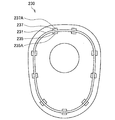
環状部材250は、ステンレスやチタン等の金属やオートクレーブ滅菌における高温高圧の水蒸気に耐性を有する樹脂からなる環状の部材である。環状部材250を構成する樹脂として、上述した第2の筐体部230を構成し得る樹脂が適用され得る。環状部材250は、第1の筐体部130と第2の筐体部230とで挟持され、カメラヘッド40の種類を識別する外周面を有する。具体的には、環状部材250は、第1の筐体部130の第1の外周面と第2の外周面との段差部と、第2の筐体部230の先端部と、により挟持される。また、環状部材250は、外観の色と、外観の形状と、外観の印刷と、の少なくともいずれかにより、カメラヘッド40を識別する。   The annular member 250 is an annular member made of a metal such as stainless steel or titanium, or a resin having resistance to high-temperature and high-pressure steam in autoclave sterilization. As the resin constituting the annular member 250, the resin that can constitute the second housing portion 230 described above can be applied. The annular member 250 is sandwiched between the first housing portion 130 and the second housing portion 230 and has an outer peripheral surface that identifies the type of the camera head 40. Specifically, the annular member 250 is sandwiched between the step portion between the first outer peripheral surface and the second outer peripheral surface of the first housing portion 130 and the tip portion of the second housing portion 230. The The annular member 250 identifies the camera head 40 by at least one of the color of appearance, the shape of appearance, and the printing of appearance.

例えば、環状部材250は、外部に露出された環状部材250の外周面の少なくとも一部の色、環状部材250の外周面に形成された溝や刻印等の形状、環状部材250の外周面の印刷等により、カメラヘッド40を識別する。環状部材250の外周面は、メッキ処理により着色されてもよい。それにより、ユーザは、環状部材250の外観の色、外観の形状、外観の印刷等を視認することによって、カメラヘッド40の使用目的や機能等を示す各種情報を識別することができる。また、環状部材250の配置される第2の筐体部230と第1の筐体部130との接続箇所は、カメラヘッド40の筐体において外径が略最大となる箇所である。なお、環状部材250の詳細については、後述する。   For example, the annular member 250 has a color of at least a part of the outer peripheral surface of the annular member 250 exposed to the outside, a shape such as a groove or a stamp formed on the outer peripheral surface of the annular member 250, and printing of the outer peripheral surface of the annular member 250. For example, the camera head 40 is identified. The outer peripheral surface of the annular member 250 may be colored by a plating process. Accordingly, the user can identify various types of information indicating the purpose and function of the camera head 40 by visually recognizing the appearance color, appearance shape, appearance printing, and the like of the annular member 250. In addition, the connection portion between the second housing portion 230 and the first housing portion 130 in which the annular member 250 is disposed is a portion where the outer diameter is substantially maximum in the housing of the camera head 40. The details of the annular member 250 will be described later.

第1のシール部材270は、高圧の水蒸気に耐性を有するシリコン樹脂等からなる略円環形状のシール部材である。第1のシール部材270は、電子部品であるコネクタ137及びケーブル50の一部を覆う第2の筐体部230と第1の筐体部130とが接続される箇所の水密性を確保するために設けられる。第1のシール部材270は、第1の筐体部130と、第2の筐体部230と、環状部材250とにより固定される。このとき、第1のシール部材270は、環状部材250、第1の筐体部130、及び第2の筐体部230と面接触する。なお、第1のシール部材270の詳細については、後述する。   The first seal member 270 is a substantially ring-shaped seal member made of silicon resin or the like that is resistant to high-pressure steam. The first seal member 270 ensures watertightness at a location where the second housing portion 230 and the first housing portion 130 that cover a part of the connector 137 and the cable 50 that are electronic components are connected. Provided. The first seal member 270 is fixed by the first housing part 130, the second housing part 230, and the annular member 250. At this time, the first seal member 270 is in surface contact with the annular member 250, the first housing portion 130, and the second housing portion 230. Details of the first seal member 270 will be described later.

調整部材290は、第2の筐体部230の後端部に設けられ、ケーブル50の一部を覆う略円筒形状の部材である。調整部材290は、第1の筐体部130と第2の筐体部230との接続方向における、第1の筐体部130に対する第2の筐体部230の相対位置を調整する。具体的には、調整部材290は、ケーブル50のケーブル部の外周部に設けられたおねじ部51に螺合されるめねじ部291を有し、調整部材290が回転することによって、当該接続方向における第1の筐体部130に対する第2の筐体部230の相対位置を調整する。   The adjustment member 290 is a substantially cylindrical member that is provided at the rear end portion of the second housing portion 230 and covers a part of the cable 50. The adjustment member 290 adjusts the relative position of the second casing unit 230 with respect to the first casing unit 130 in the connection direction between the first casing unit 130 and the second casing unit 230. Specifically, the adjustment member 290 has a female screw portion 291 that is screwed into the external screw portion 51 provided on the outer peripheral portion of the cable portion of the cable 50, and the connection is made when the adjustment member 290 rotates. The relative position of the second housing part 230 with respect to the first housing part 130 in the direction is adjusted.

より具体的には、ケーブル50のケーブル部の外周部の一部にはねじ山が形成されたおねじ部51が設けられている。また、調整部材290の内周部にはねじ溝が形成されためねじ部291が設けられており、ケーブル50のケーブル部のおねじ部51に螺合される。調整部材290の先端部は、第2のシール部材310を介して第2の筐体部230の後端部と接続される。   More specifically, a part of the outer periphery of the cable portion of the cable 50 is provided with a male screw portion 51 in which a thread is formed. In addition, a screw groove 291 is provided in the inner peripheral portion of the adjustment member 290, so that a screw portion 291 is provided and is screwed into the male screw portion 51 of the cable portion of the cable 50. The leading end portion of the adjustment member 290 is connected to the rear end portion of the second housing portion 230 via the second seal member 310.

ケーブル50に対して調整部材290が回転すると、調整部材290はめねじ部291の軸方向に移動する。めねじ部291の軸方向は、図2に示したように、第1の筐体部130の段差部と第2の筐体部230の先端部とが対向する方向と略平行である。それにより、第2の筐体部230は、第1の筐体部130と第2の筐体部230との接続方向に移動する。ゆえに、フックスパナ等の工具を用いて調整部材290を回転させることによって、第1の筐体部130に対する第2の筐体部230の相対位置を適宜調整することが可能となる。   When the adjustment member 290 rotates with respect to the cable 50, the adjustment member 290 moves in the axial direction of the female screw portion 291. As shown in FIG. 2, the axial direction of the female thread portion 291 is substantially parallel to the direction in which the step portion of the first housing portion 130 and the tip portion of the second housing portion 230 face each other. Thereby, the second casing unit 230 moves in the connecting direction between the first casing unit 130 and the second casing unit 230. Therefore, by rotating the adjustment member 290 using a tool such as a hook spanner, the relative position of the second casing 230 with respect to the first casing 130 can be adjusted as appropriate.

第2のシール部材310は、第2の筐体部230より後方に設けられる環状のシール部材である。第2のシール部材310は、電子部品であるコネクタ137及びケーブル50の一部を覆う第2の筐体部230と調整部材290とが接続される箇所の水密性を確保するために設けられる。第2のシール部材310は、第2の筐体部230の後端部と調整部材290の先端部との間に挟み込まれ、第2の筐体部230の後端部、及び調整部材290の先端部と面接触する。   The second seal member 310 is an annular seal member provided behind the second housing portion 230. The second seal member 310 is provided in order to ensure watertightness at a location where the second housing portion 230 that covers a part of the connector 137 and the cable 50 that are electronic components and the adjustment member 290 are connected. The second seal member 310 is sandwiched between the rear end portion of the second housing portion 230 and the front end portion of the adjustment member 290, and the rear end portion of the second housing portion 230 and the adjustment member 290 Makes surface contact with the tip.

(2−2.第1のシール部材の周囲の構成)
続いて、図4〜図7を参照して、第1のシール部材270の周囲の構成の詳細について説明する。図4は、図2において矩形で示した第1のシール部材270及び第1のシール部材270の周囲の構成を含む領域500の拡大図である。
(2-2. Configuration around the first seal member)
Next, the details of the configuration around the first seal member 270 will be described with reference to FIGS. 4 to 7. FIG. 4 is an enlarged view of the first seal member 270 shown in a rectangle in FIG. 2 and a region 500 including a configuration around the first seal member 270.

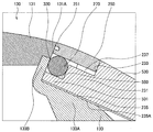
図4に示したように、前側筐体131の後端の外周部には、第2の筐体部230側へ突出する突出部131Aが設けられる。後側筐体133は、略円筒形状の側面部133Aと、側面部133Aの先端に設けられたフランジ部133Bと、からなる。前側筐体131の突出部131Aの内周部には、後側筐体133のフランジ部133Bが嵌合され、突出部131Aの内周部は、フランジ部133Bの外周部と溶接により接合される。   As shown in FIG. 4, a protruding portion 131 </ b> A that protrudes toward the second housing portion 230 is provided on the outer peripheral portion of the rear end of the front housing 131. The rear housing 133 includes a substantially cylindrical side surface portion 133A and a flange portion 133B provided at the tip of the side surface portion 133A. The flange portion 133B of the rear housing 133 is fitted into the inner peripheral portion of the protruding portion 131A of the front housing 131, and the inner peripheral portion of the protruding portion 131A is joined to the outer peripheral portion of the flange portion 133B by welding. .

前側筐体131の外周面は、本開示に係る第1の外周面に相当し、後側筐体133の側面部133Aの外周面は、第1の外周面より断面外形が小さい本開示に係る第2の外周面に相当する。前側筐体131の突出部131Aの端面、及び後側筐体133のフランジ部133Bの後面(第2の筐体部230側の面)とからなる面は、当該第1の外周面と当該第2の外周面との段差部に相当する。   The outer peripheral surface of the front housing 131 corresponds to the first outer peripheral surface according to the present disclosure, and the outer peripheral surface of the side surface 133A of the rear housing 133 has a smaller cross-sectional outer shape than the first outer peripheral surface. This corresponds to the second outer peripheral surface. The surface formed by the end surface of the protruding portion 131A of the front housing 131 and the rear surface of the flange 133B of the rear housing 133 (the surface on the second housing portion 230 side) is the first outer peripheral surface and the first outer surface. 2 corresponds to a stepped portion with the outer peripheral surface.

第2の筐体部230の先端部には、内周側に第1の筐体部130の当該段差部に向かって突出する環状凸部231が設けられる。環状凸部231は、図4に示したように、後側筐体133の側面部133Aの外周面と環状部材250の内周面との間に配置される。   An annular convex portion 231 that protrudes toward the step portion of the first housing portion 130 is provided on the inner peripheral side at the distal end portion of the second housing portion 230. As shown in FIG. 4, the annular convex portion 231 is disposed between the outer peripheral surface of the side surface portion 133 </ b> A of the rear housing 133 and the inner peripheral surface of the annular member 250.

環状凸部231には、後側筐体133の側面部133Aの外周面と環状部材250の内周面との間隔を規制するために、後側筐体133の側面部133Aの外周面及び環状部材250の内周面にそれぞれ接するリブ235及びリブ237が設けられる。リブ235とリブ237は、環状凸部231の内周面及び外周面に設けられ、環状凸部231を介して対向配置される。環状凸部231の内側を向くリブ235の面235Aが後側筐体133の側面部133Aの外周面と接し、環状凸部231の外側を向くリブ237の面237Aが環状部材250の内周面と接する。これにより、環状部材250に外側から加わる荷重はリブ237、環状凸部231、リブ235、後側筐体133で支持される。なお、本実施形態においては、リブ237を環状凸部231に設ける構成としたが、これに限らず、環状部材250の内周面側に設けてもよい。   The annular convex portion 231 includes an outer peripheral surface and an annular surface of the side surface portion 133A of the rear housing 133 in order to regulate the distance between the outer peripheral surface of the side surface portion 133A of the rear housing 133 and the inner peripheral surface of the annular member 250. Ribs 235 and ribs 237 that are in contact with the inner peripheral surface of the member 250 are provided. The rib 235 and the rib 237 are provided on the inner peripheral surface and the outer peripheral surface of the annular convex portion 231, and are disposed to face each other via the annular convex portion 231. The surface 235A of the rib 235 facing the inner side of the annular convex portion 231 is in contact with the outer peripheral surface of the side surface portion 133A of the rear housing 133, and the surface 237A of the rib 237 facing the outer side of the annular convex portion 231 is the inner peripheral surface of the annular member 250. Touch. Thereby, the load applied to the annular member 250 from the outside is supported by the rib 237, the annular convex portion 231, the rib 235, and the rear housing 133. In the present embodiment, the rib 237 is provided on the annular convex portion 231, but the present invention is not limited thereto, and the rib 237 may be provided on the inner peripheral surface side of the annular member 250.

図5は、第2の筐体部230の構成の一例を示す説明図である。図5において、第1の筐体部130と第2の筐体部230との接続方向に前側筐体131側から見た第2の筐体部230が示されている。第1の筐体部130と第2の筐体部230との接続方向に前側筐体131側から見た環状凸部231の形状は、例えば、図5紙面において縦長な略楕円形状を有し、上側に略水平な部分を有してもよい。環状凸部231には、環状凸部231を介して対向配置されるリブ235とリブ237の複数のペアが形成される。それにより、後側筐体133の側面部133Aの外周面と環状部材250の内周面との間隔を、規制することができる。例えば、リブ235の面235Aとリブ237の面237Aとの距離は、全てのペアにおいて等しく設定される。それにより、後側筐体133の側面部133Aの外周面と環状部材250の内周面との間隔を、側面部133A及び環状部材250の周方向の任意の位置において一定にすることができる。   FIG. 5 is an explanatory diagram illustrating an example of the configuration of the second casing unit 230. In FIG. 5, the second housing portion 230 viewed from the front housing 131 side is shown in the connection direction of the first housing portion 130 and the second housing portion 230. The shape of the annular convex portion 231 viewed from the front housing 131 side in the connecting direction of the first housing portion 130 and the second housing portion 230 has, for example, a substantially elliptical shape that is vertically long in the plane of FIG. The upper portion may have a substantially horizontal portion. A plurality of pairs of ribs 235 and ribs 237 are formed on the annular convex portion 231 so as to face each other via the annular convex portion 231. Thereby, the space | interval of the outer peripheral surface of 133 A of side parts of the rear side housing | casing 133 and the internal peripheral surface of the annular member 250 can be controlled. For example, the distance between the surface 235A of the rib 235 and the surface 237A of the rib 237 is set equal in all pairs. Thereby, the space | interval of the outer peripheral surface of 133 A of side parts of the rear side housing | casing 133 and the internal peripheral surface of the annular member 250 can be made constant in the arbitrary positions of the circumferential direction of 133 A of side parts and the annular member 250.

図6は、環状部材250を通り、第1の筐体部130と第2の筐体部230との接続方向に垂直な図4に示したX−X断面におけるカメラヘッド40の断面図である。図6に示したように、第1のシール部材270は、後側筐体133の側面部133Aの外周面と環状部材250の内周面とにより挟まれる。後側筐体133の側面部133A、環状部材250、及び第1のシール部材270の断面は、図5に示した環状凸部231の形状と同様に、例えば、図6紙面において縦長な略楕円形状を有し、上側に略水平な部分を有してもよい。後側筐体133の側面部133A、環状部材250、及び第1のシール部材270の断面は、図5に示した第2の筐体部230の環状凸部231の形状に対応した形状であればよく、円形状に限定されない。   6 is a cross-sectional view of the camera head 40 in the XX cross section shown in FIG. 4 that passes through the annular member 250 and is perpendicular to the connection direction of the first housing portion 130 and the second housing portion 230. . As shown in FIG. 6, the first seal member 270 is sandwiched between the outer peripheral surface of the side surface portion 133 </ b> A of the rear housing 133 and the inner peripheral surface of the annular member 250. The cross-sections of the side surface portion 133A, the annular member 250, and the first seal member 270 of the rear housing 133 are, for example, a vertically long, substantially elliptical shape in FIG. 6 as in the shape of the annular convex portion 231 shown in FIG. It may have a shape and may have a substantially horizontal portion on the upper side. The cross sections of the side surface portion 133A of the rear housing 133, the annular member 250, and the first seal member 270 may have a shape corresponding to the shape of the annular convex portion 231 of the second housing portion 230 shown in FIG. What is necessary is just and it is not limited to circular shape.

環状部材250は、第1の筐体部130と第2の筐体部230とで挟持される。例えば、図4に示したように、環状部材250は、前側筐体131の突出部131Aの端面及び後側筐体133のフランジ部133Bの後面の一部、並びに第2の筐体部230の先端部の外周側の面233により挟持される。なお、環状部材250は、後側筐体133のフランジ部133Bの後面の一部と接触しなくてもよい。   The annular member 250 is sandwiched between the first housing part 130 and the second housing part 230. For example, as illustrated in FIG. 4, the annular member 250 includes the end surface of the protruding portion 131 </ b> A of the front housing 131, a part of the rear surface of the flange portion 133 </ b> B of the rear housing 133, and the second housing portion 230. It is clamped by the outer peripheral surface 233 of the tip. The annular member 250 may not contact a part of the rear surface of the flange portion 133B of the rear housing 133.

環状部材250は、前側筐体131の突出部131Aの端面及び後側筐体133のフランジ部133Bの後面の一部、並びに第2の筐体部230の面233、とそれぞれ接着剤によって接着されてもよい。環状部材250の先端面には、環状溝251が設けられてもよい。それにより、環状部材250を第1の筐体部130と接着するための接着剤を環状溝251に溜めることができる。ゆえに、環状部材250と第1の筐体部130との接着において、環状部材250と第1の筐体部130とが接着される部分に提供される接着剤の量を増大させることができるので、接着剤により環状部材250と第1の筐体部130とが接着される面積を増大させることができる。従って、環状部材250と第1の筐体部130とを強固に接着し、かつ、環状部材250と第1の筐体部130とが接着される部分の水密性を向上させることが可能である。なお、本実施形態においては、環状溝251を環状部材250に設ける構成としたが、これに限らず、第1の筐体部130側や第2の筐体部230側に設けてもよい。   The annular member 250 is bonded to the end surface of the protruding portion 131A of the front housing 131, a part of the rear surface of the flange portion 133B of the rear housing 133, and the surface 233 of the second housing portion 230 with an adhesive. May be. An annular groove 251 may be provided on the tip surface of the annular member 250. Thereby, an adhesive for adhering the annular member 250 to the first housing part 130 can be stored in the annular groove 251. Therefore, in the bonding between the annular member 250 and the first housing portion 130, the amount of adhesive provided to the portion where the annular member 250 and the first housing portion 130 are bonded can be increased. The area where the annular member 250 and the first housing part 130 are bonded by the adhesive can be increased. Therefore, it is possible to firmly bond the annular member 250 and the first housing portion 130 and improve the water tightness of the portion where the annular member 250 and the first housing portion 130 are bonded. . In the present embodiment, the annular groove 251 is provided in the annular member 250. However, the present invention is not limited to this, and the annular groove 251 may be provided on the first housing part 130 side or the second housing part 230 side.

図4に示したように、ユーザがカメラヘッド40を使用する際に把持される部分の一部である環状部材250の断面外径は、前側筐体131及び第2の筐体部230の環状部材250と接する箇所における断面外径と略同一である。ゆえに、本実施形態において、識別用の部材である環状部材250を配置することによって、外部に露出し把持される部分に不要な凸部は形成されない。また、環状部材250の外径は先端側及び後端側からそれぞれ中央部へかけて大きくなってもよい。第1の筐体部130の段差部は、例えば、図4に示したように、環状部材250の外周面より内側に、前側筐体131の突出部131Aの内周部と後側筐体133のフランジ部133Bの外周部との溶接部330を有してもよい。   As shown in FIG. 4, the cross-sectional outer diameter of the annular member 250 that is a part of the portion that is gripped when the user uses the camera head 40 is the annular shape of the front casing 131 and the second casing 230. It is substantially the same as the cross-sectional outer diameter at the point where the member 250 contacts. Therefore, in the present embodiment, by disposing the annular member 250 that is a member for identification, unnecessary convex portions are not formed on the portion exposed to the outside and gripped. Further, the outer diameter of the annular member 250 may increase from the front end side and the rear end side toward the center portion. For example, as shown in FIG. 4, the stepped portion of the first housing portion 130 has an inner peripheral portion of the protruding portion 131 </ b> A of the front housing 131 and a rear housing 133 inside the outer peripheral surface of the annular member 250. You may have the welding part 330 with the outer peripheral part of the flange part 133B.

第1のシール部材270は、第1の筐体部130と、第2の筐体部230と、環状部材250とにより固定される。例えば、図4に示したように、第1のシール部材270は、環状部材250の内周面、後側筐体133のフランジ部133Bの後面、後側筐体133の側面部133Aの外周面、及び第2の筐体部230の先端部により固定される。具体的には、第1のシール部材270は、第2の筐体部230の環状凸部231及び後側筐体133のフランジ部133Bの後面により挟持され、後側筐体133の側面部133Aの外周面及び環状部材250の内周面により挟持される。   The first seal member 270 is fixed by the first housing part 130, the second housing part 230, and the annular member 250. For example, as shown in FIG. 4, the first seal member 270 includes the inner peripheral surface of the annular member 250, the rear surface of the flange portion 133 </ b> B of the rear housing 133, and the outer peripheral surface of the side surface portion 133 </ b> A of the rear housing 133. , And the front end portion of the second housing portion 230. Specifically, the first seal member 270 is sandwiched between the annular convex portion 231 of the second housing portion 230 and the rear surface of the flange portion 133B of the rear housing 133, and the side surface portion 133A of the rear housing 133. And the inner peripheral surface of the annular member 250.

それにより、第1のシール部材270を、第1の筐体部130と第2の筐体部230との接続方向及び当該接続方向に直交する方向にそれぞれ挟持することができる。ゆえに、第1のシール部材270の周囲に液体が侵入した場合に、侵入した液体から第1のシール部材270へ与えられる力による第1のシール部材270の変形を任意の方向において抑制することができる。従って、図2に示した電子部品であるコネクタ137及びケーブル50の一部を覆う第2の筐体部230と第1の筐体部130とが接続される箇所の水密性を確保することができる。   Thereby, the 1st seal member 270 can be clamped in the direction orthogonal to the connection direction of the 1st case part 130 and the 2nd case part 230, and the connection direction concerned, respectively. Therefore, when the liquid enters the periphery of the first seal member 270, the deformation of the first seal member 270 due to the force applied from the entered liquid to the first seal member 270 can be suppressed in an arbitrary direction. it can. Therefore, it is possible to ensure the water tightness of the location where the second housing portion 230 and the first housing portion 130 that cover a part of the connector 137 and the cable 50 which are the electronic components shown in FIG. 2 are connected. it can.

第1のシール部材270は、環状部材250、第1の筐体部130、及び第2の筐体部230と面接触する。例えば、図4に示したように、第1のシール部材270は、環状部材250の内周面、後側筐体133のフランジ部133Bの後面、後側筐体133の側面部133Aの外周面、及び第2の筐体部230の環状凸部231と面接触してもよい。それにより、環状部材250の内周面、後側筐体133のフランジ部133Bの後面、後側筐体133の側面部133Aの外周面、及び第2の筐体部230の環状凸部231のそれぞれと第1のシール部材270との接触面積を増大させることができる。   The first seal member 270 is in surface contact with the annular member 250, the first housing part 130, and the second housing part 230. For example, as shown in FIG. 4, the first seal member 270 includes the inner peripheral surface of the annular member 250, the rear surface of the flange portion 133 </ b> B of the rear housing 133, and the outer peripheral surface of the side surface portion 133 </ b> A of the rear housing 133. , And may be in surface contact with the annular convex portion 231 of the second housing portion 230. Thereby, the inner peripheral surface of the annular member 250, the rear surface of the flange portion 133 </ b> B of the rear housing 133, the outer peripheral surface of the side surface portion 133 </ b> A of the rear housing 133, and the annular convex portion 231 of the second housing portion 230. The contact area between each and the first seal member 270 can be increased.

第1のシール部材270と接触する環状部材250、第1の筐体部130、及び第2の筐体部230のそれぞれの面は平滑面であってもよい。例えば、図4に示したように、第1のシール部材270と接触する環状部材250の内周面、後側筐体133のフランジ部133Bの後面、後側筐体133の側面部133Aの外周面、及び前記第2の筐体部230の先端部のそれぞれの面は平滑面であってもよい。それにより、環状部材250の内周面、後側筐体133のフランジ部133Bの後面、後側筐体133の側面部133Aの外周面、及び前記第2の筐体部230の先端部のそれぞれと第1のシール部材270との密着性を向上させることができる。例えば、上記平滑面の中心線平均表面粗さRaは1.6μm以下である。具体的には、上記平滑面は、金属部品であれば研磨されることにより形成され、射出成形樹脂部品であれば金型の相当する面を研磨することにより形成されている。   The respective surfaces of the annular member 250, the first housing portion 130, and the second housing portion 230 that are in contact with the first seal member 270 may be smooth surfaces. For example, as shown in FIG. 4, the inner peripheral surface of the annular member 250 that contacts the first seal member 270, the rear surface of the flange portion 133 </ b> B of the rear housing 133, and the outer periphery of the side surface portion 133 </ b> A of the rear housing 133. Each surface of the surface and the distal end portion of the second housing portion 230 may be a smooth surface. Thereby, the inner peripheral surface of the annular member 250, the rear surface of the flange portion 133B of the rear housing 133, the outer peripheral surface of the side surface portion 133A of the rear housing 133, and the front end portion of the second housing portion 230, respectively. And the first seal member 270 can be improved. For example, the center line average surface roughness Ra of the smooth surface is 1.6 μm or less. Specifically, the smooth surface is formed by polishing if it is a metal part, and is formed by polishing the corresponding surface of a mold if it is an injection molded resin part.

図7は、本開示の実施形態に係るカメラヘッド40の周辺の一例の概略構成を示す分解斜視図である。カメラヘッド40の組み立てにおいて、第1の筐体部130が組み立てられた後、第1のシール部材270が、後側筐体133の側面部133Aの外周面に嵌合される。次に、環状部材250が、第1のシール部材270の外周部に嵌合される。そして、ケーブル50が、コネクタ137の後端部に接続される。次に、調整部材290のめねじ部291が、ケーブルのおねじ部51に螺合される。そして、調整部材290を回転させることによって、調整部材290に第2のシール部材310を介して接続される第2の筐体部230が、第1の筐体部130側へ移動する。そして、第1の筐体部130の段差部と第2の筐体部230の先端部によって、環状部材250及び第1のシール部材270が挟持される。   FIG. 7 is an exploded perspective view illustrating a schematic configuration of an example of the periphery of the camera head 40 according to the embodiment of the present disclosure. In assembling the camera head 40, after the first housing portion 130 is assembled, the first seal member 270 is fitted to the outer peripheral surface of the side surface portion 133 </ b> A of the rear housing 133. Next, the annular member 250 is fitted to the outer peripheral portion of the first seal member 270. The cable 50 is connected to the rear end of the connector 137. Next, the female thread portion 291 of the adjustment member 290 is screwed into the male thread portion 51 of the cable. Then, by rotating the adjustment member 290, the second housing portion 230 connected to the adjustment member 290 via the second seal member 310 moves to the first housing portion 130 side. Then, the annular member 250 and the first seal member 270 are sandwiched between the step portion of the first housing portion 130 and the tip portion of the second housing portion 230.

<3.変形例>
上記では、図4〜図7を参照して、第1のシール部材270及び第1のシール部材270の周囲の構成の詳細について説明したが、第1のシール部材270及び第1のシール部材270の周囲の構成は係る例に限定されず、他の構成であってもよい。以下、各変形例に係る第1のシール部材270及び第1のシール部材270の周囲の構成について説明する。
<3. Modification>
In the above description, the details of the configuration around the first seal member 270 and the first seal member 270 have been described with reference to FIGS. 4 to 7, but the first seal member 270 and the first seal member 270 have been described. The configuration around is not limited to such an example, and may be another configuration. Hereinafter, the 1st sealing member 270 which concerns on each modification, and the structure around the 1st sealing member 270 are demonstrated.

(3−1.第1の変形例)
図8は、第1の変形例に係る第1のシール部材270及び第1のシール部材270の周囲の構成を含む領域の拡大図である。第1の変形例に係る第2の筐体部530の環状凸部231の先端部には、内周側に第1の筐体部130の段差部に向かって突出する第2の環状凸部501が設けられる。第2の環状凸部501の先端部は、第1の筐体部130の段差部と接する。
(3-1. First Modification)
FIG. 8 is an enlarged view of a region including the first seal member 270 and the configuration around the first seal member 270 according to the first modification. A second annular convex portion that protrudes toward the stepped portion of the first casing portion 130 on the inner peripheral side at the tip of the annular convex portion 231 of the second casing portion 530 according to the first modification. 501 is provided. The tip end portion of the second annular convex portion 501 is in contact with the step portion of the first housing portion 130.

第1の変形例では、図8に示したように、第1のシール部材270は、環状部材250の内周面、後側筐体133のフランジ部133Bの後面、第2の筐体部530の第2の環状凸部501の外周面、及び第2の筐体部530の環状凸部231と第2の環状凸部501との段差部503により固定される。具体的には、第1のシール部材270は、第2の筐体部530の環状凸部231と第2の環状凸部501との段差部503及び後側筐体133のフランジ部133Bの後面により挟持され、第2の筐体部530の第2の環状凸部501の外周面及び環状部材250の内周面により挟持される。それにより、第1のシール部材270を、第1の筐体部130と第2の筐体部530との接続方向及び当該接続方向に直交する方向にそれぞれ挟持することができる。   In the first modification example, as shown in FIG. 8, the first seal member 270 includes the inner peripheral surface of the annular member 250, the rear surface of the flange portion 133 </ b> B of the rear housing 133, and the second housing portion 530. The second annular convex portion 501 and the stepped portion 503 between the annular convex portion 231 and the second annular convex portion 501 of the second casing 530 are fixed. Specifically, the first seal member 270 includes the stepped portion 503 between the annular convex portion 231 and the second annular convex portion 501 of the second casing portion 530 and the rear surface of the flange portion 133B of the rear casing 133. And is sandwiched between the outer peripheral surface of the second annular convex portion 501 and the inner peripheral surface of the annular member 250 of the second housing portion 530. Accordingly, the first seal member 270 can be sandwiched in the connection direction between the first housing portion 130 and the second housing portion 530 and in the direction orthogonal to the connection direction.

なお、第1の変形例において、リブ237は環状凸部231に設けられてもよく、環状部材250の内周面側に設けられてもよい。   In the first modified example, the rib 237 may be provided on the annular convex portion 231 or may be provided on the inner peripheral surface side of the annular member 250.

(3−2.第2の変形例)
図9は、第2の変形例に係る第1のシール部材270及び第1のシール部材270の周囲の構成を含む領域の拡大図である。第2の変形例に係る環状部材650の先端側には、内周側に向かって突出する環状部材突出部601が設けられる。環状部材突出部601の内周部は、後側筐体133の側面部133Aの外周面と接する。
(3-2. Second Modification)
FIG. 9 is an enlarged view of a region including the first seal member 270 and the configuration around the first seal member 270 according to the second modification. An annular member projecting portion 601 that projects toward the inner peripheral side is provided on the distal end side of the annular member 650 according to the second modification. The inner peripheral portion of the annular member protruding portion 601 is in contact with the outer peripheral surface of the side surface portion 133A of the rear housing 133.

第2の変形例では、図9に示したように、第1のシール部材270は、環状部材650の後端側の内周面603、環状部材650の環状部材突出部601の後面、後側筐体133の側面部133Aの外周面、及び第2の筐体部230の環状凸部231の先端部により固定される。具体的には、第1のシール部材270は、第2の筐体部230の環状凸部231の先端部及び環状部材650の環状部材突出部601の後面により挟持され、後側筐体133の側面部133Aの外周面及び環状部材650の後端側の内周面603により挟持される。それにより、第1のシール部材270を、第1の筐体部130と第2の筐体部230との接続方向及び当該接続方向に直交する方向にそれぞれ挟持することができる。   In the second modified example, as shown in FIG. 9, the first seal member 270 includes an inner peripheral surface 603 on the rear end side of the annular member 650, a rear surface, and a rear side of the annular member protrusion 601 of the annular member 650. It is fixed by the outer peripheral surface of the side surface portion 133 </ b> A of the housing 133 and the tip portion of the annular convex portion 231 of the second housing portion 230. Specifically, the first seal member 270 is sandwiched between the front end portion of the annular convex portion 231 of the second housing portion 230 and the rear surface of the annular member protruding portion 601 of the annular member 650, and The outer peripheral surface of the side surface portion 133A and the inner peripheral surface 603 on the rear end side of the annular member 650 are sandwiched. Thereby, the 1st seal member 270 can be clamped in the direction orthogonal to the connection direction of the 1st case part 130 and the 2nd case part 230, and the connection direction concerned, respectively.

なお、第2の変形例において、リブ237は環状凸部231に設けられてもよく、環状部材650の後端側の内周面603側に設けられてもよい。   In the second modification, the rib 237 may be provided on the annular convex portion 231 or may be provided on the inner peripheral surface 603 side on the rear end side of the annular member 650.

(3−3.第3の変形例)
図10は、第3の変形例に係る第1のシール部材270及び第1のシール部材270の周囲の構成を含む領域の拡大図である。第3の変形例に係る第2の筐体部730の環状凸部701は、第1の筐体部130の段差部に向かって突出するように、第2の筐体部730の先端側の外周側に設けられる。また、第3の変形例に係る環状部材850の内周面には、後側筐体133の側面部133Aの外周面と接するリブ803が設けられる。
(3-3. Third Modification)
FIG. 10 is an enlarged view of a region including the first seal member 270 and the configuration around the first seal member 270 according to the third modification. The annular convex portion 701 of the second housing portion 730 according to the third modification is on the tip side of the second housing portion 730 so as to protrude toward the step portion of the first housing portion 130. Provided on the outer peripheral side. In addition, a rib 803 that is in contact with the outer peripheral surface of the side surface portion 133A of the rear housing 133 is provided on the inner peripheral surface of the annular member 850 according to the third modification.

第3の変形例では、図10に示したように、環状部材850は、第1の筐体部130の段差部及び第2の筐体部730の環状凸部701の先端部により挟持される。また、第1のシール部材270は、第2の筐体部730の環状凸部701の内周面、環状部材850の後面、後側筐体133の側面部133Aの外周面、及び第2の筐体部730の先端部の内周側の面703により固定される。具体的には、第1のシール部材270は、第2の筐体部730の先端部の内周側の面703及び環状部材850の後面により挟持され、後側筐体133の側面部133Aの外周面及び第2の筐体部730の環状凸部701の内周面により挟持される。それにより、第1のシール部材270を、第1の筐体部130と第2の筐体部730との接続方向及び当該接続方向に直交する方向にそれぞれ挟持することができる。   In the third modified example, as illustrated in FIG. 10, the annular member 850 is sandwiched between the stepped portion of the first housing portion 130 and the distal end portion of the annular convex portion 701 of the second housing portion 730. . The first seal member 270 includes an inner peripheral surface of the annular convex portion 701 of the second housing portion 730, a rear surface of the annular member 850, an outer peripheral surface of the side surface portion 133A of the rear housing 133, and a second surface. The housing portion 730 is fixed by the inner peripheral surface 703 of the tip portion. Specifically, the first seal member 270 is sandwiched between the inner peripheral surface 703 of the front end portion of the second housing portion 730 and the rear surface of the annular member 850, so that the side surface portion 133 </ b> A of the rear housing 133 is It is sandwiched between the outer peripheral surface and the inner peripheral surface of the annular convex portion 701 of the second housing portion 730. Accordingly, the first seal member 270 can be sandwiched in the connection direction between the first housing portion 130 and the second housing portion 730 and in the direction orthogonal to the connection direction.

なお、第3の変形例において、環状凸部701にはリブは設けられず、環状凸部701より後方の第2の筐体部730の内周面に後側筐体133の側面部133Aの外周面と接するリブ705が設けられる。   In the third modified example, the annular convex portion 701 is not provided with a rib, and the side surface portion 133A of the rear housing 133 is formed on the inner peripheral surface of the second housing portion 730 behind the annular convex portion 701. Ribs 705 are provided in contact with the outer peripheral surface.

また、図8〜10を用いて説明した各変形例において、第1のシール部材270は、第1のシール部材270と接する各部材のそれぞれと面接触してもよい。また、第1のシール部材270と接する各部材のそれぞれの面は閉滑面であってもよい。   Moreover, in each modification demonstrated using FIGS. 8-10, the 1st sealing member 270 may surface-contact with each of each member which contact | connects the 1st sealing member 270. FIG. Further, each surface of each member in contact with the first seal member 270 may be a closed smooth surface.

<4.効果>
上述した実施形態によれば、環状部材250は、第1の筐体部130と第2の筐体部230とで挟持される。第1のシール部材270は、第1の筐体部130と、環状部材250と、第2の筐体部230とにより固定される。
<4. Effect>
According to the embodiment described above, the annular member 250 is sandwiched between the first housing part 130 and the second housing part 230. The first seal member 270 is fixed by the first housing part 130, the annular member 250, and the second housing part 230.

それにより、第1のシール部材270を、略直交する2つの方向にそれぞれ挟持することができる。ゆえに、第1のシール部材270の周囲に液体が侵入した場合に、侵入した液体から第1のシール部材270へ与えられる力による第1のシール部材270の変形を任意の方向において抑制することができる。従って、電子部品であるコネクタ137及びケーブル50の一部を覆う第2の筐体部230と第1の筐体部130とが接続される箇所の水密性を確保することができる。それにより、カメラヘッド40の外観端部に識別用の部材である環状部材250を配置することが可能となるので、不要な凸部を形成させることなく、識別力を向上することができる。従って、識別性を損なうことなく、新規かつ改良された医療用カメラ装置を提案することが可能である。   Accordingly, the first seal member 270 can be sandwiched in two directions substantially orthogonal to each other. Therefore, when the liquid enters the periphery of the first seal member 270, the deformation of the first seal member 270 due to the force applied from the entered liquid to the first seal member 270 can be suppressed in an arbitrary direction. it can. Therefore, it is possible to ensure water tightness at a location where the second housing portion 230 and the first housing portion 130 that cover a part of the connector 137 and the cable 50 that are electronic components are connected. Thereby, since it becomes possible to arrange | position the annular member 250 which is a member for identification to the external appearance edge part of the camera head 40, discrimination power can be improved, without forming an unnecessary convex part. Therefore, it is possible to propose a new and improved medical camera device without impairing discrimination.

また、ある実施形態によれば、環状部材250、第1の筐体部130、及び第2の筐体部230は、第1のシール部材270と面接触する。それにより、環状部材250、第1の筐体部130、及び第2の筐体部230のそれぞれと第1のシール部材270との接触面積を増大させることができる。ゆえに、第1のシール部材270の周囲に液体が侵入し、侵入した液体から第1のシール部材270へ与えられる力により第1のシール部材270が変形した場合であっても、第1のシール部材270の変形量が所定の変形量以下であれば、第2の筐体部230と第1の筐体部130との接続箇所の水密性を確保することができる。   Further, according to an embodiment, the annular member 250, the first housing part 130, and the second housing part 230 are in surface contact with the first seal member 270. Thereby, the contact area between each of the annular member 250, the first housing part 130, and the second housing part 230 and the first seal member 270 can be increased. Therefore, even if the liquid enters the periphery of the first seal member 270 and the first seal member 270 is deformed by the force applied to the first seal member 270 from the invaded liquid, the first seal member 270 is deformed. If the deformation amount of the member 270 is equal to or less than the predetermined deformation amount, it is possible to ensure the water tightness of the connection portion between the second housing portion 230 and the first housing portion 130.

また、ある実施形態によれば、第2の筐体部230の先端部には、第1の筐体部130の段差部に向かって突出し、第1の筐体部130の第2の外周面と環状部材250の内周面との間に配置される環状凸部231が設けられ、第1のシール部材270は、第1の筐体部130の段差部と環状凸部231とにより挟持される。それにより、環状凸部231が突出する長さに応じて、環状凸部231が第1のシール部材270に押し込まれる量が決定される。ゆえに、第1のシール部材270の寸法や材質を考慮して、環状凸部231が突出する長さを設定することにより、環状凸部231が第1のシール部材270に押し込まれる量を適正化することができる。   Further, according to an embodiment, the distal end portion of the second housing portion 230 protrudes toward the step portion of the first housing portion 130, and the second outer peripheral surface of the first housing portion 130. And an annular convex portion 231 disposed between the annular member 250 and the inner peripheral surface of the annular member 250, and the first seal member 270 is sandwiched between the step portion of the first housing portion 130 and the annular convex portion 231. The Thereby, the amount by which the annular protrusion 231 is pushed into the first seal member 270 is determined in accordance with the length of the protrusion of the annular protrusion 231. Therefore, considering the size and material of the first seal member 270, the length by which the annular convex portion 231 is pushed into the first seal member 270 is optimized by setting the length that the annular convex portion 231 protrudes. can do.

また、ある実施形態によれば、第2の筐体部230の環状凸部231には、第1の筐体部130の第2の外周面及び環状部材250の内周面に接する複数のリブが設けられる。それにより、第1の筐体部130の第2の外周面と環状部材250の内周面との間隔を、規制することができる。ゆえに、第1のシール部材270が第1の筐体部130の第2の外周面及び環状部材250の内周面に挟まれることによって第1のシール部材270に掛かる力の分布の変化を抑制することができる。従って、第1の筐体部130の第2の外周面と環状部材250の内周面との間隔の変化による第1のシール部材270の変形を抑制することが可能である。   In addition, according to an embodiment, the annular convex portion 231 of the second housing portion 230 has a plurality of ribs that are in contact with the second outer peripheral surface of the first housing portion 130 and the inner peripheral surface of the annular member 250. Is provided. Thereby, the space | interval of the 2nd outer peripheral surface of the 1st housing | casing part 130 and the internal peripheral surface of the annular member 250 can be controlled. Therefore, when the first seal member 270 is sandwiched between the second outer peripheral surface of the first housing portion 130 and the inner peripheral surface of the annular member 250, a change in the distribution of force applied to the first seal member 270 is suppressed. can do. Therefore, it is possible to suppress the deformation of the first seal member 270 due to the change in the distance between the second outer peripheral surface of the first housing portion 130 and the inner peripheral surface of the annular member 250.

また、ある実施形態によれば、第2の筐体部230の後端部には、第1の筐体部130と第2の筐体部230との接続方向における、第1の筐体部130に対する第2の筐体部230の相対位置を調整する調整部材290が設けられる。ゆえに、第1の筐体部130に対する第2の筐体部230の相対位置を調整することによって、第2の筐体部230の先端部が第1のシール部材270に押し込まれる量を調整することができる。   In addition, according to an embodiment, the rear end portion of the second casing portion 230 has the first casing portion in the connection direction between the first casing portion 130 and the second casing portion 230. An adjustment member 290 that adjusts the relative position of the second casing 230 with respect to 130 is provided. Therefore, by adjusting the relative position of the second casing 230 with respect to the first casing 130, the amount by which the tip of the second casing 230 is pushed into the first seal member 270 is adjusted. be able to.

また、ある実施形態によれば、第1の筐体部130の段差部は、環状部材250の外周面より内側に溶接部330を有する。それにより、溶接部330は、環状部材250及び環状部材250の後方に位置する第2の筐体部230により覆われるため、外部に露出しない。ゆえに、外観の設計の自由度を向上させることが可能である。   In addition, according to an embodiment, the step portion of the first housing portion 130 has the welded portion 330 on the inner side of the outer peripheral surface of the annular member 250. Thereby, since the welding part 330 is covered with the 2nd housing | casing part 230 located behind the annular member 250 and the annular member 250, it is not exposed outside. Therefore, the degree of freedom in designing the appearance can be improved.

また、ある実施形態によれば、第1のシール部材270と接触する環状部材250、第1の筐体部130、及び第2の筐体部230のそれぞれの面は平滑面である。それにより、環状部材250、第1の筐体部130、及び第2の筐体部230のそれぞれと第1のシール部材270との密着性を向上させることができる。ゆえに、第2の筐体部230と第1の筐体部130との接続箇所の水密性を向上させることができる。   Moreover, according to an embodiment, each surface of the annular member 250, the first housing part 130, and the second housing part 230 that contacts the first seal member 270 is a smooth surface. Thereby, the adhesiveness between each of the annular member 250, the first housing portion 130, and the second housing portion 230 and the first seal member 270 can be improved. Therefore, it is possible to improve the water tightness of the connection portion between the second casing portion 230 and the first casing portion 130.

また、ある実施形態によれば、上記平滑面は研磨されている。通常、部材の面を研磨することによって、当該部材の面の表面粗さの値を低下させることができる。ゆえに、上記平滑面を研磨することによって、上記平滑面の滑らかさを向上させることができる。従って、環状部材250、第1の筐体部、及び第2の筐体部230のそれぞれと第1のシール部材270との密着性をさらに向上させることができる。   According to an embodiment, the smooth surface is polished. Usually, the value of the surface roughness of the surface of the member can be reduced by polishing the surface of the member. Therefore, the smoothness of the smooth surface can be improved by polishing the smooth surface. Therefore, the adhesion between the first seal member 270 and each of the annular member 250, the first housing portion, and the second housing portion 230 can be further improved.

<5.むすび>
以上説明したように、本開示の実施形態によれば、環状部材は、第1の筐体と第2の筐体とで挟持される。シール部材は、第1の筐体と、環状部材と、第2の筐体とにより固定される。
<5. Conclusion>
As described above, according to the embodiment of the present disclosure, the annular member is sandwiched between the first casing and the second casing. The seal member is fixed by the first housing, the annular member, and the second housing.

それにより、シール部材を、略直交する2つの方向にそれぞれ挟持することができる。ゆえに、シール部材の周囲に液体が侵入した場合に、侵入した液体からシール部材へ与えられる力によるシールの変形を任意の方向において抑制することができる。従って、電子部品であるコネクタ部及びケーブルの一部を覆う第2の筐体と第1の筐体とが接続される箇所の水密性を確保することができる。それにより、カメラヘッドの外観端部に識別用の部材である環状部材を配置することが可能となるので、不要な凸部を形成させることなく、識別力を向上することができる。従って、識別性を損なうことなく、新規かつ改良された医療用カメラ装置を提案することが可能である。   Thereby, the seal member can be clamped in two directions substantially orthogonal to each other. Therefore, when liquid enters the periphery of the seal member, deformation of the seal due to the force applied to the seal member from the entered liquid can be suppressed in an arbitrary direction. Therefore, it is possible to ensure watertightness at a location where the second housing and the first housing that cover a part of the connector portion and the cable that are electronic components are connected. Thereby, since it becomes possible to arrange | position the annular member which is a member for identification to the external appearance edge part of a camera head, discrimination power can be improved, without forming an unnecessary convex part. Therefore, it is possible to propose a new and improved medical camera device without impairing discrimination.

また、以上では、カメラヘッド40に設けられ、一端に外部のケーブル50が着脱可能に接続されるコネクタ部であるコネクタ137を有するカメラヘッド40について説明したが、例えば、図2に示したコネクタ接続基板190に外部のケーブル50の信号線を直接接続してコネクタ部を有さない外部のケーブル50がカメラヘッド40と一体的に接続された構成とすることも可能である。   In the above description, the camera head 40 having the connector 137 that is a connector portion provided on the camera head 40 and to which an external cable 50 is detachably connected at one end has been described. For example, the connector connection shown in FIG. It is also possible to connect the signal line of the external cable 50 directly to the substrate 190 and connect the external cable 50 having no connector part integrally with the camera head 40.

また、以上では、本開示の実施形態に係るカメラヘッドが内視鏡装置に用いられる例について説明したが、本開示に係るカメラヘッドを備える医療用カメラ装置は係る例に限定されない。例えば、本開示に係る医療用カメラ装置は、医療用顕微鏡装置であってもよい。医療用顕微鏡装置は、外科手術において、術部を拡大観察しながら手術を行うために用いられる観察装置である。医療用顕微鏡装置は、撮像装置と、当該撮像装置を保持し、当該撮像装置の位置及び姿勢を移動及び固定することが可能なアーム装置と、を備える。本開示に係るカメラヘッドは、例えば、このような医療用顕微鏡装置の撮像装置として適用され得る。そして、本開示に係る信号伝送部は、例えば、このような医療用顕微鏡装置のアーム装置として適用され得る。また、このような医療用顕微鏡装置において、アーム装置に2つのカメラヘッドが保持されてもよい。   Further, the example in which the camera head according to the embodiment of the present disclosure is used in the endoscope apparatus has been described above, but the medical camera apparatus including the camera head according to the present disclosure is not limited to the example. For example, the medical camera device according to the present disclosure may be a medical microscope device. The medical microscope apparatus is an observation apparatus used for performing an operation while observing an operation part in an enlarged manner in a surgical operation. The medical microscope apparatus includes an imaging device and an arm device that holds the imaging device and can move and fix the position and posture of the imaging device. The camera head according to the present disclosure can be applied as an imaging apparatus of such a medical microscope apparatus, for example. And the signal transmission part which concerns on this indication can be applied as an arm apparatus of such a medical microscope apparatus, for example. Further, in such a medical microscope apparatus, two camera heads may be held by the arm device.

以上、添付図面を参照しながら本開示の好適な実施形態について詳細に説明したが、本開示の技術的範囲は係る例に限定されない。本開示の技術分野における通常の知識を有する者であれば、特許請求の範囲に記載された技術的思想の範疇内において、各種の変更例または修正例に想到し得ることは明らかであり、これらについても、当然に本開示の技術的範囲に属するものと了解される。   The preferred embodiments of the present disclosure have been described in detail above with reference to the accompanying drawings, but the technical scope of the present disclosure is not limited to such examples. It is obvious that a person having ordinary knowledge in the technical field of the present disclosure can come up with various changes or modifications within the scope of the technical idea described in the claims. Of course, it is understood that it belongs to the technical scope of the present disclosure.

また、本明細書に記載された効果は、あくまで説明的または例示的なものであって限定的ではない。つまり、本開示に係る技術は、上記の効果とともに、又は上記の効果に代えて、本明細書の記載から当業者には明らかな他の効果を奏しうる。   Further, the effects described in the present specification are merely illustrative or exemplary and are not limited. That is, the technology according to the present disclosure can exhibit other effects that are apparent to those skilled in the art from the description of the present specification in addition to or instead of the above effects.

なお、以下のような構成も本開示の技術的範囲に属する。
(1)
撮像素子を収納する第1の筐体を備えるカメラヘッドと、
前記カメラヘッドと接続され少なくとも前記撮像素子からの画像信号を伝送するケーブル部と、前記ケーブル部が挿通される筒状の第2の筐体と、を備える信号伝送部と、
前記第1の筐体と前記第2の筐体とで挟持され、前記カメラヘッドの種類を識別する外周面を有する環状部材と、
前記第1の筐体と前記第2の筐体と前記環状部材とにより固定される環状のシール部材と、
を備える医療用カメラ装置。
(2)
前記カメラヘッドの前記第1の筐体は、第1の外周面と、前記信号伝送部の前記ケーブル部が接続される接続部が設けられるとともに前記第1の外周面より断面外形が小さい第2の外周面と、を備え、
前記環状部材と、前記シール部材と、前記第2の筐体の少なくとも先端部と、は前記第1の筐体の第2の外周面を挿通し配設され、
前記環状部材は、前記第1の筐体の前記第1の外周面と前記第2の外周面との段差部と、前記第2の筐体の先端部と、により挟持される、
前記(1)に記載の医療用カメラ装置。
(3)
前記環状部材、前記第1の筐体、及び前記第2の筐体は、前記シール部材と面接触する、前記(1)又は(2)に記載の医療用カメラ装置。
(4)
前記環状部材は、外観の色と、外観の形状と、外観の印刷と、の少なくともいずれかにより、前記カメラヘッドを識別する、前記(1)〜(3)のいずれか一項に記載の医療用カメラ装置。
(5)
前記第2の筐体の前記先端部には、前記第1の筐体の前記段差部に向かって突出し、前記第2の外周面と前記環状部材の内周面との間に配置される環状凸部が設けられ、
前記シール部材は、前記第1の筐体の前記段差部と前記第2の筐体の前記環状凸部とにより挟持される、
前記(2)に記載の医療用カメラ装置。
(6)
前記環状凸部には、前記第2の外周面及び前記環状部材の内周面に接する複数のリブが設けられる、前記(5)に記載の医療用カメラ装置。
(7)
前記第2の筐体の後端部には、前記第1の筐体と前記第2の筐体との接続方向における、前記第1の筐体に対する前記第2の筐体の相対位置を調整する調整部材が設けられる、前記(1)〜(6)のいずれか一項に記載の医療用カメラ装置。
(8)
前記調整部材は、前記ケーブル部の外周部に設けられたおねじ部に螺合されるめねじ部を有し、前記調整部材が回転することによって、前記相対位置を前記接続方向に調整する、前記(7)に記載の医療用カメラ装置。
(9)
前記シール部材と接触する前記環状部材、前記第1の筐体、及び前記第2の筐体のそれぞれの面は平滑面である、前記(3)に記載の医療用カメラ装置。
(10)
前記平滑面の中心線平均表面粗さRaは1.6μm以下である、前記(9)に記載の医療用カメラ装置。
The following configurations also belong to the technical scope of the present disclosure.
(1)
A camera head comprising a first housing for housing an image sensor;
A signal transmission unit including a cable unit connected to the camera head and transmitting at least an image signal from the imaging element; and a cylindrical second housing through which the cable unit is inserted;
An annular member sandwiched between the first casing and the second casing and having an outer peripheral surface for identifying the type of the camera head;
An annular seal member fixed by the first housing, the second housing, and the annular member;
A medical camera device comprising:
(2)
The first casing of the camera head is provided with a first outer peripheral surface and a connection portion to which the cable portion of the signal transmission unit is connected, and a second sectional outer shape is smaller than the first outer peripheral surface. An outer peripheral surface of
The annular member, the seal member, and at least the tip of the second casing are disposed through the second outer peripheral surface of the first casing,
The annular member is sandwiched between a step portion between the first outer peripheral surface and the second outer peripheral surface of the first casing and a tip end portion of the second casing.
The medical camera device according to (1).
(3)
The medical camera device according to (1) or (2), wherein the annular member, the first housing, and the second housing are in surface contact with the seal member.
(4)
The medical device according to any one of (1) to (3), wherein the annular member identifies the camera head by at least one of an appearance color, an appearance shape, and an appearance print. Camera device.
(5)
The tip of the second casing protrudes toward the stepped portion of the first casing and is disposed between the second outer peripheral surface and the inner peripheral surface of the annular member. Convex is provided,
The seal member is sandwiched between the step portion of the first housing and the annular convex portion of the second housing.
The medical camera device according to (2).
(6)
The medical camera device according to (5), wherein the annular protrusion is provided with a plurality of ribs in contact with the second outer peripheral surface and the inner peripheral surface of the annular member.
(7)
The rear end of the second casing adjusts the relative position of the second casing with respect to the first casing in the connection direction between the first casing and the second casing. The medical camera device according to any one of (1) to (6), wherein an adjustment member is provided.
(8)
The adjustment member has a female screw portion that is screwed to a male screw portion provided on an outer peripheral portion of the cable portion, and the adjustment member rotates to adjust the relative position in the connection direction. The medical camera device according to (7) above.
(9)
The medical camera device according to (3), wherein each surface of the annular member, the first housing, and the second housing that is in contact with the seal member is a smooth surface.
(10)
The medical camera device according to (9), wherein a center line average surface roughness Ra of the smooth surface is 1.6 μm or less.

1 内視鏡装置
10 挿入部
20 光源装置
30 ライトガイド
40 カメラヘッド
50 ケーブル
51 おねじ部
60 制御装置
70 表示装置
110 カプラ部
130 第1の筐体部
131 前側筐体
131A 突出部
133 後側筐体
133A 側面部
133B フランジ部
135 スイッチ
137 コネクタ
150 レンズユニット
170 主基板
171 撮像素子実装部
173 信号処理部
175 電子部品実装部
190 コネクタ接続基板
210 スイッチ接続基板
230、530、730 第2の筐体部
231、701 環状凸部
235、237、705、803 リブ
250、650、850 環状部材
251 環状溝
270 第1のシール部材
290 調整部材
291 めねじ部
310 第2のシール部材
330 溶接部
DESCRIPTION OF SYMBOLS 1 Endoscope apparatus 10 Insertion part 20 Light source apparatus 30 Light guide 40 Camera head 50 Cable 51 Male thread part 60 Control apparatus 70 Display apparatus 110 Coupler part 130 1st housing | casing part 131 Front side housing | casing 131A Protrusion part 133 Rear side housing Body 133A Side part 133B Flange part 135 Switch 137 Connector 150 Lens unit 170 Main board 171 Imaging element mounting part 173 Signal processing part 175 Electronic component mounting part 190 Connector connection board 210 Switch connection board 230, 530, 730 Second housing part 231, 701 Annular convex parts 235, 237, 705, 803 Ribs 250, 650, 850 Annular member 251 Annular groove 270 First seal member 290 Adjustment member 291 Female thread part 310 Second seal member 330 Welding part

Claims (9)

撮像素子を収納する第1の筐体を備えるカメラヘッドと、
前記カメラヘッドと接続され少なくとも前記撮像素子からの画像信号を伝送するケーブル部と、前記ケーブル部が挿通される筒状の第2の筐体と、を備える信号伝送部と、
前記第1の筐体と前記第2の筐体とで挟持され、前記カメラヘッドの種類を識別する外周面を有する環状部材と、
前記第1の筐体と前記第2の筐体と前記環状部材とにより固定される環状のシール部材と、
を備え
前記環状部材、前記第1の筐体、及び前記第2の筐体は、前記シール部材と面接触する、
医療用カメラ装置。
A camera head comprising a first housing for housing an image sensor;
A signal transmission unit including a cable unit connected to the camera head and transmitting at least an image signal from the imaging element; and a cylindrical second housing through which the cable unit is inserted;
An annular member sandwiched between the first casing and the second casing and having an outer peripheral surface for identifying the type of the camera head;
An annular seal member fixed by the first housing, the second housing, and the annular member;
Equipped with a,
The annular member, the first housing, and the second housing are in surface contact with the seal member.
Medical camera device.
前記カメラヘッドの前記第1の筐体は、第1の外周面と、前記信号伝送部の前記ケーブル部が接続される接続部が設けられるとともに前記第1の外周面より断面外形が小さい第2の外周面と、を備え、
前記環状部材と、前記シール部材と、前記第2の筐体の少なくとも先端部と、は前記第1の筐体の第2の外周面を挿通し配設され、
前記環状部材は、前記第1の筐体の前記第1の外周面と前記第2の外周面との段差部と、前記第2の筐体の先端部と、により挟持される、
請求項1に記載の医療用カメラ装置。
The first casing of the camera head is provided with a first outer peripheral surface and a connection portion to which the cable portion of the signal transmission unit is connected, and a second sectional outer shape is smaller than the first outer peripheral surface. An outer peripheral surface of
The annular member, the seal member, and at least the tip of the second casing are disposed through the second outer peripheral surface of the first casing,
The annular member is sandwiched between a step portion between the first outer peripheral surface and the second outer peripheral surface of the first casing and a tip end portion of the second casing.
The medical camera device according to claim 1.
前記環状部材は、外観の色と、外観の形状と、外観の印刷と、の少なくともいずれかにより、前記カメラヘッドを識別する、請求項1に記載の医療用カメラ装置。   The medical camera device according to claim 1, wherein the annular member identifies the camera head by at least one of an appearance color, an appearance shape, and an appearance print. 前記第2の筐体の前記先端部には、前記第1の筐体の前記段差部に向かって突出し、前記第2の外周面と前記環状部材の内周面との間に配置される環状凸部が設けられ、
前記シール部材は、前記第1の筐体の前記段差部と前記第2の筐体の前記環状凸部とにより挟持される、
請求項2に記載の医療用カメラ装置。
The tip of the second casing protrudes toward the stepped portion of the first casing and is disposed between the second outer peripheral surface and the inner peripheral surface of the annular member. Convex is provided,
The seal member is sandwiched between the step portion of the first housing and the annular convex portion of the second housing.
The medical camera device according to claim 2.
前記環状凸部には、前記第2の外周面及び前記環状部材の内周面に接する複数のリブが設けられる、請求項に記載の医療用カメラ装置。 The medical camera device according to claim 4 , wherein the annular convex portion is provided with a plurality of ribs in contact with the second outer peripheral surface and the inner peripheral surface of the annular member. 前記第2の筐体の後端部には、前記第1の筐体と前記第2の筐体との接続方向における、前記第1の筐体に対する前記第2の筐体の相対位置を調整する調整部材が設けられる、請求項1に記載の医療用カメラ装置。   The rear end of the second casing adjusts the relative position of the second casing with respect to the first casing in the connection direction between the first casing and the second casing. The medical camera device according to claim 1, wherein an adjustment member is provided. 前記調整部材は、前記ケーブル部の外周部に設けられたおねじ部に螺合されるめねじ部を有し、前記調整部材が回転することによって、前記相対位置を前記接続方向に調整する、請求項に記載の医療用カメラ装置。 The adjustment member has a female screw portion that is screwed to a male screw portion provided on an outer peripheral portion of the cable portion, and the adjustment member rotates to adjust the relative position in the connection direction. The medical camera device according to claim 6 . 前記シール部材と接触する前記環状部材、前記第1の筐体、及び前記第2の筐体のそれぞれの面は平滑面である、請求項に記載の医療用カメラ装置。 The medical camera device according to claim 1 , wherein each surface of the annular member, the first housing, and the second housing that is in contact with the seal member is a smooth surface. 前記平滑面の中心線平均表面粗さRaは1.6μm以下である、請求項に記載の医療用カメラ装置。 The medical camera device according to claim 8 , wherein a center line average surface roughness Ra of the smooth surface is 1.6 μm or less.
JP2015104596A 2015-05-22 2015-05-22 Medical camera device Active JP6576098B2 (en)

Priority Applications (1)

Application Number Priority Date Filing Date Title
JP2015104596A JP6576098B2 (en) 2015-05-22 2015-05-22 Medical camera device

Applications Claiming Priority (1)

Application Number Priority Date Filing Date Title
JP2015104596A JP6576098B2 (en) 2015-05-22 2015-05-22 Medical camera device

Publications (2)

Publication Number Publication Date
JP2016214661A JP2016214661A (en) 2016-12-22
JP6576098B2 true JP6576098B2 (en) 2019-09-18

Family

ID=57579614

Family Applications (1)

Application Number Title Priority Date Filing Date
JP2015104596A Active JP6576098B2 (en) 2015-05-22 2015-05-22 Medical camera device

Country Status (1)

Country Link
JP (1) JP6576098B2 (en)

Families Citing this family (2)

* Cited by examiner, † Cited by third party
Publication number Priority date Publication date Assignee Title
JP6752288B2 (en) 2016-11-01 2020-09-09 本田技研工業株式会社 Power storage device, transportation equipment and control method
JP6867204B2 (en) 2017-03-17 2021-04-28 ソニー・オリンパスメディカルソリューションズ株式会社 Camera head for endoscope

Family Cites Families (6)

* Cited by examiner, † Cited by third party
Publication number Priority date Publication date Assignee Title
JPH085452Y2 (en) * 1986-02-14 1996-02-14 オリンパス光学工業株式会社 Endoscope eyepiece device
JPH07184827A (en) * 1993-12-28 1995-07-25 Olympus Optical Co Ltd Endoscope
US5868664A (en) * 1996-02-23 1999-02-09 Envision Medical Corporation Electrically isolated sterilizable endoscopic video camera head
JP4832776B2 (en) * 2005-03-15 2011-12-07 オリンパスメディカルシステムズ株式会社 Endoscope
JP5147887B2 (en) * 2009-04-02 2013-02-20 オリンパスメディカルシステムズ株式会社 Endoscopic imaging device
JP2013056003A (en) * 2011-09-07 2013-03-28 Olympus Medical Systems Corp Imaging device and endoscope

Also Published As

Publication number Publication date
JP2016214661A (en) 2016-12-22

Similar Documents

Publication Publication Date Title
JP5074146B2 (en) Capsule medical device
US10517468B2 (en) Capsule medical device having positioning member with abutment surfaces
US11122969B2 (en) Endoscopic device
US20100016670A1 (en) Capsule medical device and method of manufacturing capsule medical device
CN106886088B (en) Endoscope with a detachable handle
JP7353447B2 (en) Camera head for endoscope
JP6576098B2 (en) Medical camera device
WO2015133254A1 (en) Imaging device and endoscopic device
JP5147887B2 (en) Endoscopic imaging device
US20210338057A1 (en) Endoscope distal end portion and endoscope
JP6594660B2 (en) Medical camera head and medical camera device
JP6302863B2 (en) Endoscope device
US20200241280A1 (en) Endoscope distal end portion, endoscope, and method of manufacturing endoscope distal end portion
JP7099891B2 (en) Endoscope connector and endoscope
CN113544566A (en) Connector device for endoscope
JP2016214660A (en) Medical camera head and medical camera device
CN108601503B (en) Switch unit, endoscope imaging device provided with switch unit, and endoscope provided with switch unit
US9537574B2 (en) Optical transmitting and receiving unit
JP7181170B2 (en) Endoscope imaging device and endoscope
JP2005204924A (en) Capsule type endoscope
JP2021037209A (en) Endoscope imaging device and endoscope
JPWO2015056568A1 (en) Endoscope
JP2018153472A (en) Endoscope camera head
JPWO2016047172A1 (en) Optical transceiver unit
JP6450873B2 (en) Endoscope device

Legal Events

Date Code Title Description
A621 Written request for application examination

Free format text: JAPANESE INTERMEDIATE CODE: A621

Effective date: 20180404

A977 Report on retrieval

Free format text: JAPANESE INTERMEDIATE CODE: A971007

Effective date: 20190128

RD04 Notification of resignation of power of attorney

Free format text: JAPANESE INTERMEDIATE CODE: A7424

Effective date: 20190208

RD04 Notification of resignation of power of attorney

Free format text: JAPANESE INTERMEDIATE CODE: A7424

Effective date: 20190222

A131 Notification of reasons for refusal

Free format text: JAPANESE INTERMEDIATE CODE: A131

Effective date: 20190226

A521 Written amendment

Free format text: JAPANESE INTERMEDIATE CODE: A523

Effective date: 20190426

RD02 Notification of acceptance of power of attorney

Free format text: JAPANESE INTERMEDIATE CODE: A7422

Effective date: 20190426

RD04 Notification of resignation of power of attorney

Free format text: JAPANESE INTERMEDIATE CODE: A7424

Effective date: 20190522

TRDD Decision of grant or rejection written
A01 Written decision to grant a patent or to grant a registration (utility model)

Free format text: JAPANESE INTERMEDIATE CODE: A01

Effective date: 20190723

A61 First payment of annual fees (during grant procedure)

Free format text: JAPANESE INTERMEDIATE CODE: A61

Effective date: 20190820

R150 Certificate of patent or registration of utility model

Ref document number: 6576098

Country of ref document: JP

Free format text: JAPANESE INTERMEDIATE CODE: R150