JP6574427B2 - Recirculation filter for housing - Google Patents
Recirculation filter for housing Download PDFInfo
- Publication number
- JP6574427B2 JP6574427B2 JP2016550798A JP2016550798A JP6574427B2 JP 6574427 B2 JP6574427 B2 JP 6574427B2 JP 2016550798 A JP2016550798 A JP 2016550798A JP 2016550798 A JP2016550798 A JP 2016550798A JP 6574427 B2 JP6574427 B2 JP 6574427B2
- Authority
- JP
- Japan
- Prior art keywords
- filter
- sheet
- filter media
- adsorbent
- media sheet
- Prior art date
- Legal status (The legal status is an assumption and is not a legal conclusion. Google has not performed a legal analysis and makes no representation as to the accuracy of the status listed.)
- Active
Links
Images


Classifications
-
- G—PHYSICS
- G11—INFORMATION STORAGE
- G11B—INFORMATION STORAGE BASED ON RELATIVE MOVEMENT BETWEEN RECORD CARRIER AND TRANSDUCER
- G11B33/00—Constructional parts, details or accessories not provided for in the other groups of this subclass
- G11B33/14—Reducing influence of physical parameters, e.g. temperature change, moisture, dust
- G11B33/1446—Reducing contamination, e.g. by dust, debris
- G11B33/146—Reducing contamination, e.g. by dust, debris constructional details of filters
-
- B—PERFORMING OPERATIONS; TRANSPORTING
- B01—PHYSICAL OR CHEMICAL PROCESSES OR APPARATUS IN GENERAL
- B01D—SEPARATION
- B01D24/00—Filters comprising loose filtering material, i.e. filtering material without any binder between the individual particles or fibres thereof
- B01D24/007—Filters comprising loose filtering material, i.e. filtering material without any binder between the individual particles or fibres thereof with multiple filtering elements in series connection
- B01D24/008—Filters comprising loose filtering material, i.e. filtering material without any binder between the individual particles or fibres thereof with multiple filtering elements in series connection arranged concentrically or coaxially
-
- B—PERFORMING OPERATIONS; TRANSPORTING
- B01—PHYSICAL OR CHEMICAL PROCESSES OR APPARATUS IN GENERAL
- B01D—SEPARATION
- B01D39/00—Filtering material for liquid or gaseous fluids
- B01D39/14—Other self-supporting filtering material ; Other filtering material
- B01D39/16—Other self-supporting filtering material ; Other filtering material of organic material, e.g. synthetic fibres
- B01D39/1607—Other self-supporting filtering material ; Other filtering material of organic material, e.g. synthetic fibres the material being fibrous
-
- B—PERFORMING OPERATIONS; TRANSPORTING
- B01—PHYSICAL OR CHEMICAL PROCESSES OR APPARATUS IN GENERAL
- B01D—SEPARATION
- B01D39/00—Filtering material for liquid or gaseous fluids
- B01D39/14—Other self-supporting filtering material ; Other filtering material
- B01D39/20—Other self-supporting filtering material ; Other filtering material of inorganic material, e.g. asbestos paper, metallic filtering material of non-woven wires
- B01D39/2055—Carbonaceous material
- B01D39/2058—Carbonaceous material the material being particulate
-
- B—PERFORMING OPERATIONS; TRANSPORTING
- B01—PHYSICAL OR CHEMICAL PROCESSES OR APPARATUS IN GENERAL
- B01J—CHEMICAL OR PHYSICAL PROCESSES, e.g. CATALYSIS OR COLLOID CHEMISTRY; THEIR RELEVANT APPARATUS
- B01J20/00—Solid sorbent compositions or filter aid compositions; Sorbents for chromatography; Processes for preparing, regenerating or reactivating thereof
- B01J20/02—Solid sorbent compositions or filter aid compositions; Sorbents for chromatography; Processes for preparing, regenerating or reactivating thereof comprising inorganic material
- B01J20/20—Solid sorbent compositions or filter aid compositions; Sorbents for chromatography; Processes for preparing, regenerating or reactivating thereof comprising inorganic material comprising free carbon; comprising carbon obtained by carbonising processes
-
- B—PERFORMING OPERATIONS; TRANSPORTING
- B01—PHYSICAL OR CHEMICAL PROCESSES OR APPARATUS IN GENERAL
- B01D—SEPARATION
- B01D2239/00—Aspects relating to filtering material for liquid or gaseous fluids
- B01D2239/12—Special parameters characterising the filtering material
- B01D2239/1258—Permeability
-
- B—PERFORMING OPERATIONS; TRANSPORTING
- B01—PHYSICAL OR CHEMICAL PROCESSES OR APPARATUS IN GENERAL
- B01D—SEPARATION
- B01D2253/00—Adsorbents used in seperation treatment of gases and vapours
-
- B—PERFORMING OPERATIONS; TRANSPORTING
- B01—PHYSICAL OR CHEMICAL PROCESSES OR APPARATUS IN GENERAL
- B01D—SEPARATION
- B01D2279/00—Filters adapted for separating dispersed particles from gases or vapours specially modified for specific uses
- B01D2279/45—Filters adapted for separating dispersed particles from gases or vapours specially modified for specific uses for electronic devices, e.g. computers, hard-discs, mobile phones
-
- B—PERFORMING OPERATIONS; TRANSPORTING
- B01—PHYSICAL OR CHEMICAL PROCESSES OR APPARATUS IN GENERAL
- B01D—SEPARATION
- B01D39/00—Filtering material for liquid or gaseous fluids
-
- G—PHYSICS
- G11—INFORMATION STORAGE
- G11B—INFORMATION STORAGE BASED ON RELATIVE MOVEMENT BETWEEN RECORD CARRIER AND TRANSDUCER
- G11B33/00—Constructional parts, details or accessories not provided for in the other groups of this subclass
- G11B33/14—Reducing influence of physical parameters, e.g. temperature change, moisture, dust
Description
関連出願の相互参照
本出願は、DONALDSON COMPANY, INC.(米国国内企業)(全ての指定国に対する出願人)、およびStanley B. Miller, III(米国民);Allen N. Nicklay(米国民);Christopher J. Fischer(米国民);およびDaniel L. Tuma(米国民)(指定の州のみに対する発明人)の名義で、2015年2月12日にPCT国際特許出願として出願されており、および2014年2月13日出願の米国仮特許出願第61/939,683号明細書の優先権を主張し、それらの内容全体が、参照することにより本書に援用される。
CROSS REFERENCE TO RELATED APPLICATIONS This application is a registered application of DONALDSON COMPANY, INC. (US domestic companies) (applicants for all designated countries), and Stanley B. Miller, III (US citizens); Nicklay (US citizens); Christopher J. et al. Fischer (US citizens); and Daniel L. US Provisional Patent Application No. 61, filed on February 12, 2015 as a PCT international patent application in the name of Tuma (inventor only for designated states) and filed on February 13, 2014. / 939,683, which claims priority, the entire contents of which are hereby incorporated by reference.
本技術は、電子機器筐体において使用するためのフィルターに関する。特に、本技術は、電子機器筐体の内部を循環する汚染物質を除去するためのフィルターに関する。 The present technology relates to a filter for use in an electronic device casing. In particular, the present technology relates to a filter for removing contaminants circulating inside an electronic device casing.
ハードディスクドライブ筐体などの電子機器筐体内の汚染物質は、筐体内の構成要素の効率を下げ、かつ寿命を短くし得る。汚染物質は、化学物質および粒状物質を含むことがあり、および外部電源からハードドライブ筐体に入ることができるか、または製造または使用中に筐体内で生成され得る。汚染物質は、ドライブを徐々に損傷してドライブ性能を低下させ、かつさらには、ドライブを完全に故障させ得る。それゆえ、ハードディスクドライブなどのデータ記憶システムは、一般に、ディスクドライブ筐体内の空気中の粒状物質および/または汚染化学物質を除去できるまたはそれらをそこに入らないようにすることができる1つ以上のフィルターを含む。そのようなフィルターの1つのタイプは再循環フィルターであり、このフィルターは、一般的に、ディスクドライブ内で1つ以上のディスクが回転することによって生じる空気の流れの経路から汚染物質を濾過して取り除くことができるように、配置される。既存の再循環フィルターは、多くの汚染物質を除去できるが、ある種の汚染物質、特に、汚染化学物質を除去する性能の改善に対するニーズが存在する。 Contaminants in electronic equipment enclosures such as hard disk drive enclosures can reduce the efficiency of the components in the enclosure and shorten the lifetime. Contaminants can include chemicals and particulate matter and can enter the hard drive enclosure from an external power source or can be generated within the enclosure during manufacture or use. Contaminants can gradually damage the drive and reduce drive performance, and can even cause the drive to fail completely. Therefore, a data storage system, such as a hard disk drive, generally has one or more that can remove particulate matter and / or contaminant chemicals in the air within the disk drive housing or prevent them from entering it. Includes a filter. One type of such a filter is a recirculation filter, which typically filters contaminants from the air flow path caused by the rotation of one or more disks within the disk drive. Arranged so that it can be removed. Existing recirculation filters can remove many pollutants, but there is a need for improved performance in removing certain pollutants, particularly polluting chemicals.
以下の図面を参照して、この技術をより完全に説明する。 This technique is more fully described with reference to the following drawings.
本技術の原理は、様々な修正および代替形態の影響を受けやすいが、それらの詳細を、図面に例として示してあり、かつ詳細に説明する。しかしながら、本技術を、説明する特定の実施形態に限定するものではないことを理解されたい。反対に、本開示および特許請求の趣旨および範囲内にある全ての修正例、等価物、および代替例を網羅するものとする。 While the principles of the technology are susceptible to various modifications and alternatives, details thereof are shown by way of example in the drawings and will be described in detail. However, it should be understood that the technology is not limited to the specific embodiments described. On the contrary, the intent is to cover all modifications, equivalents, and alternatives falling within the spirit and scope of the disclosure and claims.
ディスクドライブアセンブリ、ならびに他の電子機器筐体から汚染物質を減少させるまたは除去するために使用される様々なフィルタリングシステムが知られている。特に、再循環フィルターは、ディスクドライブ筐体に入ったまたはディスクドライブの使用中に生成された粒状物質および/または汚染化学物質を減少させるまたは除去するために使用されることが多い。典型的な再循環フィルターは、ディスクの回転によって誘発された空気流の経路に位置決めされるフィルター素子を含み、空気流中に存在する汚染物質が濾過されるようにする。 Various filtering systems are known that are used to reduce or remove contaminants from disk drive assemblies, as well as other electronics housings. In particular, recirculation filters are often used to reduce or remove particulate matter and / or contaminating chemicals that enter a disk drive housing or that are generated during use of the disk drive. A typical recirculation filter includes a filter element that is positioned in the path of the air flow induced by the rotation of the disk so that contaminants present in the air flow are filtered.
例示的な実施形態では、フィルターアセンブリは、第1の濾材シートおよび第2の濾材シートがそれらそれぞれの周囲領域で互いに結合されたフィルター構造と、濾材の層の間に配置された吸着材とを有する。 In an exemplary embodiment, the filter assembly includes a filter structure in which a first filter media sheet and a second filter media sheet are bonded together in their respective surrounding regions, and an adsorbent disposed between layers of filter media. Have.
一般的に、透過性スクリム材などの支持層は、フィルター構造の少なくとも一部分を形成し得る。フィルターアセンブリの内部凹部内には濾材が配置され、濾材は、支持層を少なくとも部分的に覆う。例示的な実施形態では、濾材は、支持層の全てまたはほとんどの上に置かれる。別の例示的な実施形態では、支持層は、濾材内に埋め込まれる。いくつかの実施形態では、濾材および支持層は、濾材層を形成するために、フィルターアセンブリの生産前に一緒に組み合わされ(例えば、ラミネーション、熱ボンディング、または光カレンダリング(light calendaring)などによって)、その後、フィルターアセンブリの少なくとも一部分を作り出す媒質構造に形成される。 In general, a support layer such as a permeable scrim material may form at least a portion of the filter structure. A filter medium is disposed within the internal recess of the filter assembly, and the filter medium at least partially covers the support layer. In an exemplary embodiment, the filter media is placed on all or most of the support layer. In another exemplary embodiment, the support layer is embedded in the filter media. In some embodiments, the filter media and the support layer are combined together prior to production of the filter assembly to form the filter media layer (eg, by lamination, thermal bonding, or light calendaring, etc.) And then formed into a media structure that creates at least a portion of the filter assembly.
一部の実施形態では、支持層は透過性スクリム材であり、透過性スクリム材は、織りまたは不織の材料、例えばポリプロピレン繊維を含む。一部の実施形態では、支持層の水の透過性は、例えば、0.5インチで約100ft./分〜0.5インチで約800ft./分とし得る。一部の実施形態では、スクリム材の水の透過性は、0.5インチで約250ft./分、および0.5インチで約600ft./分である。さらに他の実装例では、支持層の水の透過性は、0.5インチで約300ft./分、および0.5インチで約500ft./分である。好適な支持層材の水の透過性は、例えば、0.5インチで100ft./分超;0.5インチで250ft./分超;または0.5インチで300ft./分超とし得ることが理解される。好適な支持層材の水の透過性は、例えば、一部の実施形態では、0.5インチで約800ft./分未満;一部の実施形態では0.5インチで600ft./分未満;または一部の実施形態では0.5インチで500ft./分未満をとし得る。 In some embodiments, the support layer is a permeable scrim material, and the permeable scrim material comprises a woven or non-woven material, such as polypropylene fibers. In some embodiments, the water permeability of the support layer is, for example, about 100 ft. At 0.5 inches. Per minute to 0.5 inches and about 800 ft. / Min. In some embodiments, the scrim material has a water permeability of about 250 ft. At 0.5 inches. / Min, and about 600 ft. At 0.5 inches. / Min. In yet another implementation, the support layer has a water permeability of about 300 ft. / Min, and about 500 ft. At 0.5 inches. / Min. A suitable support layer material has a water permeability of, for example, 100 ft. At 0.5 inches. / Min; 0.5 ft. 250 ft./min. / Min; or 300 ft. It is understood that it may be greater than / minute. A suitable support layer material has a water permeability of, for example, about 800 ft. At 0.5 inches in some embodiments. Less than / minute; in some embodiments, 0.5 inches and 600 ft. Less than / minute; or in some embodiments 500 ft. </ Min.
本明細書で開示する技術に適合する濾材は、本質的に静電材料とし得る。様々な実施形態では、濾材のフィギュアオブメリットは、約60を上回る。フィギュアオブメリットは、本開示に関連する電子機器ハウジングを含む様々な濾過環境においてストリームを十分に浄化するためのフィルターや濾材の能力を評価するために、計算され得る。フィギュアオブメリットは、10.5ft./分の速度および0.5インチH2OのFrazier透過性を有する空気の流れ中の、サイズ0.3μmの粒子に関して決定される分別効率(fractional efficiency)に基づいて、計算される。 Filter media compatible with the technology disclosed herein can be essentially an electrostatic material. In various embodiments, the figure of merit of the filter media is greater than about 60. Figure of merit can be calculated to evaluate the ability of filters and filter media to adequately purify streams in a variety of filtration environments including electronics housings related to the present disclosure. The figure of merit is 10.5 ft. Calculated based on fractional efficiency determined for particles of size 0.3 μm in an air stream with a speed of / min and a Frazier permeability of 0.5 inches H 2 O.
下記でより十分に説明するフィギュアオブメリットは、フィギュアオブメリットプライム(Figure of Merit Prime)(FOM’)と呼ばれる別の特性と同様である。FOM’は、媒質の分別効率を抵抗で除した値であると定義される。フィギュアオブメリットプライムを説明する式は:

分別効率は、媒質を規定の空気の流速で通過する空気から除去される、規定のサイズの粒子の割合または百分率である。出願人らは、粒子サイズ0.3μmおよび空気の流速10.5ft./分に基づいて分別効率を決定することが好都合であることを見出した。粒子サイズ0.3μmは、実際は、0.3〜0.4μmの粒子の分布を反映していることを理解すべきである。 The fractionation efficiency is the fraction or percentage of particles of a defined size that are removed from the air passing through the medium at a defined air flow rate. Applicants have stated that the particle size is 0.3 μm and the air flow rate is 10.5 ft. We have found it convenient to determine the fractionation efficiency based on / min. It should be understood that a particle size of 0.3 μm actually reflects a distribution of particles between 0.3 and 0.4 μm.
抵抗は、空気の流速に応じたフィルターの圧力低下の勾配である。便宜上、選択された単位は、圧力低下に関しては数インチの水、および空気の流速に関しては毎分フィートである。そこで、抵抗の単位は、数インチH2O/ft./分である。 Resistance is the slope of the filter pressure drop as a function of air flow rate. For convenience, the selected units are a few inches of water for pressure drop and feet per minute for air flow rate. Therefore, the unit of resistance is several inches H 2 O / ft. / Min.
所与の濾材の抵抗を得ることは困難であり得るため、好都合な代替としてFrazier透過性を使用する。Frazier透過性は、半インチの水圧(0.5”H2O)で媒質を通る線形の空気の流速である。フィギュアオブメリット(FOM:Figure of Merit)は:
FOM=分別効率×2×Frazier透過性
である。
Frazier permeability is used as a convenient alternative because it can be difficult to obtain the resistance of a given filter media. Frazier permeability is the linear air flow rate through a medium at half-inch water pressure (0.5 "H 2 O). The figure of merit (FOM) is:
FOM = fractionation efficiency × 2 × Frazier permeability.
Frazier透過性は、規定の空気の流速または体積流量において数インチの水(”H2O)での単位で得られた圧力低下(ΔP)の測定値から計算される。Frazier透過性は、空気の流速に0.5を乗じて、圧力低下で割ることによって推定される。体積流量は、媒質の面積で割ることによって空気の流速に変換され得ること、および空気の流速は、毎分フィート(ft./分)に変換すべきであることを認識すべきである。 Frazier permeability is calculated from pressure drop (ΔP) measurements obtained in units of a few inches of water ("H 2 O) at a specified air flow rate or volumetric flow rate. Multiplied by 0.5 and divided by the pressure drop, the volumetric flow rate can be converted to the air flow rate by dividing by the area of the medium, and the air flow rate is expressed in feet per minute ( ft./min) should be recognized.
濾材としてまだ組み立てられていない層の組み合わせのFOMを予測するために、分別効率は、個々の層の透過性の総計として計算され得る。層の組み合わせの総Frazier透過性は、個々の層それぞれのFrazier透過性の逆数の和の逆数である。そのため、総FOMは、総Frazier透過性で乗じて2を乗じた、総透過性である。 In order to predict the FOM of a combination of layers not yet assembled as filter media, the fractionation efficiency can be calculated as the sum of the permeability of the individual layers. The total Frazier permeability of a layer combination is the reciprocal of the sum of the reciprocal of the Frazier permeability of each individual layer. Thus, the total FOM is the total permeability multiplied by 2 multiplied by the total Frazier permeability.
再循環フィルターに関し、可能な限り高いFOMを提供することが望ましいとし得る。高いFOMは、高透過性に対応し、これは、循環している空気ストリームに配置されたフィルターに重要である。本明細書で開示する技術に一致する再循環フィルターのFOM値は、少なくとも約60であり、およびいくつかの実施形態では、少なくとも約150である。一般的に、FOMは、約50〜約250、またはさらには約150〜約200とし得る。 For recirculation filters, it may be desirable to provide the highest possible FOM. High FOM corresponds to high permeability, which is important for filters placed in the circulating air stream. A FOM value for a recirculation filter consistent with the techniques disclosed herein is at least about 60, and in some embodiments, at least about 150. Generally, the FOM can be about 50 to about 250, or even about 150 to about 200.
濾材は様々な繊維を含むことができ、および任意選択的に、ポリプロピレンおよびアクリル繊維を含む繊維媒質と混合される。濾材の水の透過性は、例えば、0.5インチで約250ft./分〜0.5インチで約750ft./分とし得る。一部の実施形態では、濾材の粉塵捕集効率は、0.1〜0.3ミクロンの粒子状汚染物質に対し約20%〜約99.99%である。好適な濾材の粉塵捕集効率は、例えば0.1〜0.3ミクロンの粒子状汚染物質に対し20%超;0.1〜0.3ミクロンの粒子状汚染物質に対し40%超;または0.1〜0.3ミクロンの粒子状汚染物質に対し60%超とし得る。いくつかの例示的な実装例では、濾材の粉塵捕集効率は、0.1〜0.3ミクロンの粒子状汚染物質に対し99.99%未満;0.1〜0.3ミクロンの粒子状汚染物質に対し80%未満;または0.1〜0.3ミクロンの粒子状汚染物質に対し60%未満とし得る。 The filter media can include a variety of fibers and is optionally mixed with a fiber medium including polypropylene and acrylic fibers. The water permeability of the filter media is, for example, about 250 ft. At 0.5 inches. Per minute to 0.5 inches and about 750 ft. / Min. In some embodiments, the filter media has a dust collection efficiency of about 20% to about 99.99% for 0.1 to 0.3 micron particulate contaminants. Suitable filter media dust collection efficiencies are, for example, greater than 20% for 0.1-0.3 micron particulate contaminants; greater than 40% for 0.1-0.3 micron particulate contaminants; or It can be over 60% for 0.1 to 0.3 micron particulate contaminants. In some exemplary implementations, the filter media dust collection efficiency is less than 99.99% for 0.1 to 0.3 micron particulate contaminants; 0.1 to 0.3 micron particulate It may be less than 80% for contaminants; or less than 60% for 0.1-0.3 micron particulate contaminants.
様々な実施形態では、本明細書で開示する技術に一致する濾過媒質は、静電繊維である。本明細書では、用語「静電繊維」は、電荷を含む繊維を指す。フィルターアセンブリ200に静電繊維を含むことの1つの利点は、フィルターが、汚染物質を機械的に捕獲できるだけでなく、電荷を含む汚染物質に静電力を加えることができ、それにより、気流から除去される汚染物質の量を増やすことである。静電媒質は、摩擦電気媒質、エルクトレット媒質、または粒子除去のための主機構として帯電できるかまたは帯電に依存する任意の他の媒質とし得る。例示的な実施形態では、静電媒質は摩擦電気繊維を含む。摩擦電気繊維は公知であり、および、例えば、(1)ポリエチレン、ポリプロピレン、またはエチレンおよびプロピレンコポリマーなどのポリオレフィン繊維と、(2)別のポリマーの繊維、例えば、ハロゲン原子、例えば塩素によって置換された炭化水素官能基を含有する繊維、またはポリアクリロニトリル繊維との混合物を使用して形成され得る。概して、ポリオレフィン繊維および他のポリマーの繊維は、約60:40または約20:80または約30:70の重量比で静電媒質に含まれる。
In various embodiments, the filtration medium consistent with the techniques disclosed herein is an electrostatic fiber. As used herein, the term “electrostatic fiber” refers to a fiber that contains a charge. One advantage of including electrostatic fibers in the
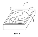
ここで、図面を参照すると、図1は、ディスクドライブ100の単純化した斜視図である。ディスクドライブ100は、筐体104を画成するハウジング本体102を有する。例示的な実施形態では、筐体104内に少なくとも1つのディスク106が回転可能に取り付けられている。ディスクの回転は、矢印によって示し(反対向きの回転が代替的に可能ではあるが)、ここでは、ディスクの回転によって、筐体104内に空気の流れを引き起こす。読み書きヘッドなどの他のディスクドライブコンポーネント、および配線が、アマーチャ108に組み込まれ得る。
Referring now to the drawings, FIG. 1 is a simplified perspective view of a
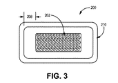
図2および図3は、比較のために本明細書で開示する公知のフィルターアセンブリ200の断面図である。吸着要素と呼ばれ得る炭分202が、第1の支持層および静電フィルター材の第1の層を有する第1のシート206と、第2の支持層および静電フィルター材の第2の層を有する第2のシート204との間に配置され、および炭分202は、第1のシート206および第2のシート204によって画成された空洞の一部分を満たす。炭分202は、一般的に、フィルターアセンブリ200を通過する空気を濾過するのを助けるように構成され、および複数の炭素ビーズ216が接着されたスクリム層214を有する。
2 and 3 are cross-sectional views of a known
第1のシート206の周囲領域は、炭分202の周りで、第2のシート204の周囲領域に溶接され、クリアランス208を生じる。クリアランス208は、溶接部210と炭分202との間のフィルターの一部分を説明している。図2および図3に示す設計では、炭分は、一般的に、製造プロセスに必要とされるクリアランス208に起因して、媒質の領域よりも小さいサイズにされる。クリアランス208は、溶接プロセスの最中に、炭分202の一部分が層間で溶接されないようにすることを保証し得る。炭分202の一部分が層間で溶接される場合、フィルターは、欠陥を有するとして不良品にされ得る。フィルターが不良品にされず、および電子機器筐体で使用される場合、炭分202の一部分が筐体に対する粒子汚染物となり得る。フィルターの外形寸法が小さくなるにつれて、炭分202の領域は、さらに大きく削減される可能性がある。フィルターがより小さくなるため、比較的平坦な媒質を炭素の上側で曲がるようにし得ることがより困難になり、およびより厚みの薄い炭分202を使用する必要性が生じ得る。
The surrounding area of the
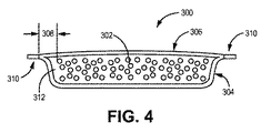
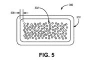
図4および図5は、本明細書で開示する技術に一致する、少なくとも第1のシート304、第2のシート306、および第1のシート304と第2のシート306との間に画成された空洞312内に配置された吸着体302を有するフィルターアセンブリ300の断面図である。第1のシート304は、一般的に、第2のシート306の周囲領域に結合されてリム領域310を形成し得る第1の周囲領域を有する。様々な実施形態では、リム領域310は、例として熱溶接や超音波溶接での溶接領域である。
4 and 5 are defined at least between the
フィルターアセンブリ300は、一般的に、空気から粒子および汚染化学物質を濾過するように構成されている。様々な実施形態では、フィルターアセンブリ300は、電子機器筐体内に位置決めされて、その内部の空気を濾過するように構成されている。いくつかの実施形態では、フィルターアセンブリ300は、ディスクドライブ内に位置決めされて、ディスクドライブ内の空気を濾過するように構成されている。フィルターアセンブリの他の使用も認識される。
様々な実施形態では、第1のシート304および第2のシート306は、一般的に、本明細書で既に説明した濾材のタイプに適合する濾材の層である。第1のシート304および第2のシート306は、空気から微粒子を濾過するように構成され得る。様々な実施形態では、第1のシート304は、一般的に、第1の支持層が結合されたフィルター材の第1の層で構成され得る。同様に、第2のシート306は、一般的に、第2の支持層が結合されたフィルター材の第2の層で構成され得る。第1の支持層および第2の支持層は、本明細書で既に説明した支持層と一致でき、および少なくとも一実施形態では、第1の支持層および第2の支持層は、同じ材料で構成される。一般的に、例えば透過性、効率性、FOM、圧力低下などのフィルターの状況に基づいて、所望のフィルターのパラメータを達成する限り、任意の数の層が結合されて、第1のシート304および第2のシート306を形成し得ることが理解される。
In various embodiments, the
いくつかの実施形態では、第1のシート304、第2のシート306、または両シート304、306は、既に説明した静電繊維で少なくとも部分的に構成され得る。少なくとも一実施形態では、第2のシート306は、第1のシート304と同じ材料である。別の実施形態では、第1のシート304および第2のシート306は、異なる材料である。例えば、一実施形態では、第2のシート306は、第1のシート304に溶接、融合または他の方法でボンディングされるスクリーン層とし得る。いくつかのそのような実施形態では、第1のシート304は、溶接された静電濾材層と支持層とを有し、およびスクリーン層は、リム領域310内で濾材の層に溶接され得る。スクリーン層は、一般的に、空気がスクリーン層を通ってフィルターアセンブリ300の空洞312内まで通過できるようにし得る。スクリーン層は、さらに、フィルターアセンブリ300が所望の構成を保持するのを支援するなどのために、支持体を提供し得る。
In some embodiments, the
現在の実施形態では、第1のシート304は、空洞312の形状を少なくとも部分的に規定する。空洞312は、少なくとも1つの例示的な実施形態では実質的に自立し得るが、別の例示的な実施形態では実質的に自立しない。用語「実質的に自立」を使用して、第1のシート304が、大気重力に対して空洞312の存在を保持する能力を有することを意味する。現在の実施形態では、第2のシート306は実質的に平面的である、つまり、第2のシート306自体の構造は空洞を画成しない;むしろ、第2のシート306の構造は、第1の濾材シート304によって画成された空洞を囲う。
In the current embodiment, the
吸着体302は、空洞312内で、第1のシート304と第2のシート306との間に配置され得る。吸着体302は、一般的に、フィルターアセンブリ300の環境内にある空気から汚染化学物質を吸着するように構成される。吸着材は、例えば、乾燥材(すなわち、水や水蒸気を吸着もしくは吸収する材料)、または揮発性有機化合物、酸性ガスを吸着もしくは吸収する材料、またはそれら双方などの物理吸着(physisorbent)材または化学吸着(chemisorbent)材とし得る。好適な吸着材は、例えば、活性炭、活性アルミナ、モレキュラーシーブ、シリカゲル、過マンガン酸カリウム、炭酸カルシウム、炭酸カリウム、炭酸ナトリウム、硫酸カルシウム、またはそれらの混合物を含む。吸着体302は、一般的に、複数の吸着ビーズである。様々な実施形態では、吸着体302は、複数の活性炭素ビーズである。吸着ビーズのサイズは、約0.2mm〜約1.1mm、0.4mm〜約1.0mm、および約0.3mm〜約0.9mmに及び得る。一実施形態では、吸着ビーズの平均サイズは、約0.3mm〜約0.8mm、または約0.6mmである。
The adsorbent 302 may be disposed between the
いくつかの実施形態では、複数の吸着ビーズのかなりの部分がボンディングされていない、つまり、吸着ビーズのかなりの部分が互いにボンディングされておらず、およびフィルターアセンブリ内の任意の他の要素にボンディングされていない。少なくとも一実施形態では、複数の吸着ビーズのそれぞれは、完全にはボンディングされていない。「かなりの部分」によって、少なくとも70%、80%、90%、95%またはさらには98%の吸着ビーズがボンディングされていないことを意味する。ボンディングされていないビーズは、吸着に利用可能な表面積が大きくなる、フィルター自体の透過性を高めるという相対的有利性を有し、および、例えば低ダスティングを有し得る。図4および図5に示すようなフィルターアセンブリ300によって画成されたクリアランス308は狭くでき、および空洞内には、図2および図3に示すフィルター素子と比較してより多くの吸着体302が配置され得る。実施形態では、フィルターアセンブリ300は、約8.5mm×20mmにでき、および厚さ約4mmとし得る。吸着体302として炭素ビーズを有する実施形態では、炭素ビーズの質量は、少なくとも35mgであり、および一般的には、約55mg以下、例えば約45mgである。実施形態では、フィルターアセンブリ300は、約4mm×15.5mmにでき、および少なくとも20mgおよび一般的に約45mg以下、例えば約33mgの質量の炭素ビーズを含み得る。
In some embodiments, a significant portion of the plurality of adsorption beads is not bonded, i.e., a substantial portion of the adsorption beads are not bonded to each other and bonded to any other element in the filter assembly. Not. In at least one embodiment, each of the plurality of adsorption beads is not fully bonded. By “significant part” is meant that at least 70%, 80%, 90%, 95% or even 98% of the adsorbent beads are not bonded. Unbonded beads have the relative advantage of increasing the surface area available for adsorption, increasing the permeability of the filter itself, and may have, for example, low dusting. The
本明細書で開示する技術に一致するフィルター構成は、フィルター(例えば活性炭)に含まれ得る吸着材の量の相対的増加を可能にする一方、比較的コンパクトなサイズを保持し、およびフィルター性能を改善する。特に、いくつかの実施形態では、本明細書で説明したフィルターは、活性炭の量を増やし得る一方、実質的にフィルターを通る空気の流れを保ち、それにより、筐体内の汚染物質レベルをより低くすること、および長期間、それらの低い濃度レベルを維持することを可能にする。 A filter configuration consistent with the technology disclosed herein allows for a relative increase in the amount of adsorbent that can be included in the filter (eg, activated carbon) while retaining a relatively compact size and improving filter performance. Improve. In particular, in some embodiments, the filters described herein can increase the amount of activated carbon while substantially maintaining the flow of air through the filter, thereby lowering contaminant levels in the housing. And maintain their low concentration levels for long periods of time.
図6は、本明細書で開示する技術に一致するフィルターアセンブリ300の例示的な実装例を示す。フィルターアセンブリ300は、一般的に、図4〜5に示す実施形態と一致し、および電子機器筐体(electronic enclosure)100を画成するハウジング内に設置される(筐体100の隅のみ示す)。フィルターアセンブリ300は、第1のシート304、第2のシート306、および第1のシート304と第2のシート306との間に配置された吸着体302を有する。フィルターアセンブリの向きは、第2のシート306の表面領域が、回転するディスク106によって生成された空気ストリーム(矢印によって方向を示す)に対面するようにされる。電子機器筐体100は、フィルターアセンブリ300を受け入れるように構成されるフィルターマウント120を有する。図示の実施形態では、フィルターアセンブリ300の第2のシート306への空気の流れの方向を支援するためにバッフル114が存在し、およびバッフル114は、フィルターマウント120を少なくとも部分的に画成する。フィルターアセンブリ300は、電子機器筐体内に配置されて、バッフル114が空気を第2のシート306の方へおよびそれを通るように向けるようにする。いくつかの実装例では、バッフル114は、任意の取付要素、またはハウジングの他の部分と共に、第2のシート306へと空気を向けるチャンネルを形成する。他の実装例では、フィルターアセンブリ300は、フィルターアセンブリ300を通るように空気の流れを向ける単一の画成されたチャンネルが存在しない電子機器筐体内を流れる空気ストリーム中に位置決めされるように構成されるか、または筐体内に、フィルターアセンブリ300を通るように空気を部分的に向ける、側面が開放しているチャンネルが形成され得る。
FIG. 6 illustrates an exemplary implementation of a
試験結果
図2〜3に示しかつ本明細書で説明する比較例に適合する例示的なフィルター構成では、第1の再循環フィルターは、第1のシートおよび第2のシートがそれらのそれぞれの周囲でボンディングされて構成された。炭素ビーズが結合されたスクリム層を有する炭分は、第1のシートと第2のシートとの間に配置された。第1のシートおよび第2のシートのそれぞれは、静電濾材の層と、ポリプロピレンスクリム層とで構成された。第1の再循環フィルターは、幅15.4mm、高さ8.9mm、および厚さ2.8mmであった。この第1の再循環フィルターは、約1mmの溶接周囲を有した。この第1の再循環フィルターは、13.4mm×6.9mm、すなわち約92mm2の活性濾過面積を有し、そこでは、活性濾過面積は、ボンディングされた周囲内で濾過に利用可能なフィルターの流れ面の面積に基づいて測定された。再循環フィルターの流れ面は、濾過の最中に空気の流れを直接受けるように構成されるフィルター面である。炭分は、幅8.1mm、高さ3.6mm、および吸着面の面積約29mm2であり、ここでは、吸着面の面積は、再循環フィルターの流れ面から測定された、吸着体(例えば炭素ビーズ)を含むフィルターの面積の測定値であった。そのようなものとして、第1の例示的な再循環フィルターに関し、吸着面の面積は、炭分自体の面積と等しかった。炭分の面積は、再循環フィルターの活性濾過面積の約35%であった。吸着要素は、8mgの炭素の質量を有した。
Test Results In an exemplary filter configuration that fits the comparative example shown in FIGS. 2-3 and described herein, the first recirculation filter has a first sheet and a second sheet around their respective surroundings. It was configured with bonding. A charcoal with a scrim layer to which carbon beads were bound was placed between the first sheet and the second sheet. Each of the first sheet and the second sheet was composed of an electrostatic filter material layer and a polypropylene scrim layer. The first recirculation filter was 15.4 mm wide, 8.9 mm high, and 2.8 mm thick. This first recirculation filter had a weld circumference of about 1 mm. This first recirculation filter has an active filtration area of 13.4 mm × 6.9 mm, ie about 92 mm 2 , where the active filtration area is the filter available for filtration within the bonded perimeter. Measured based on the area of the flow surface. The flow surface of the recirculation filter is a filter surface that is configured to receive an air flow directly during filtration. The carbon content is 8.1 mm wide, 3.6 mm high, and an adsorption surface area of about 29 mm 2 , where the adsorption surface area is measured by an adsorbent (eg, from the flow surface of the recirculation filter) It was a measured value of the area of the filter including carbon beads. As such, for the first exemplary recirculation filter, the area of the adsorption surface was equal to the area of the charcoal itself. The area of charcoal was about 35% of the active filtration area of the recirculation filter. The adsorbing element had a mass of 8 mg carbon.
第2の例示的な再循環フィルターは、図4〜5に示す実施形態に従って作製された。第2の再循環フィルターは、第1のシート、および第2のシートを有し、それらは、それらのそれぞれの周囲で接合されていた。第1のシートおよび第2のシートのそれぞれは、静電濾材の層と、ポリプロピレンスクリム層とで構成された。第1のシートは、その周囲から凹んでいる空洞を画成し、および空洞は、第1のシートと第2のシートとの間に画成された。第2の再循環フィルターの厚さは、4.8mmであった。空洞は、幅約10.9mm×高さ4.4mm×奥行3mmであった。空洞の体積は、約120mm3であった。空洞は、45mgのボンディングされていない活性炭素ビーズで満たされていた。第2の再循環フィルターの炭素ビーズの吸着面の面積は、約48mm2であった。 A second exemplary recirculation filter was made according to the embodiment shown in FIGS. The second recirculation filter had a first sheet and a second sheet, which were joined around their respective circumferences. Each of the first sheet and the second sheet was composed of an electrostatic filter material layer and a polypropylene scrim layer. The first sheet defined a cavity recessed from its periphery, and the cavity was defined between the first sheet and the second sheet. The thickness of the second recirculation filter was 4.8 mm. The cavity was about 10.9 mm wide x 4.4 mm high x 3 mm deep. The volume of the cavity was about 120 mm 3 . The cavities were filled with 45 mg of unbonded activated carbon beads. The area of the adsorption surface of the carbon beads of the second recirculation filter was about 48 mm 2 .
上述の通り、本明細書では、吸着面の面積は、再循環フィルターの流れ面から測定された、吸着体を含むフィルターの面積の測定値として使用される。第2の例示的な再循環フィルター炭素面の面積は、Itasca、ILを本拠地としているKeyence Corporation製の、Keyence VH−Z20Rレンズを有するVHX−1000デジタル顕微鏡を使用して測定された。60Wの柔らかい白色の白熱電球をバックライトとして使用した。 As described above, in this specification, the area of the adsorption surface is used as a measurement of the area of the filter including the adsorbent, measured from the flow surface of the recirculation filter. The area of the second exemplary recirculation filter carbon surface was measured using a VHX-1000 digital microscope with a Keyence VH-Z20R lens from Keyence Corporation, based in Itasca, IL. A 60 W soft white incandescent bulb was used as the backlight.
特に、顕微鏡レンズは、顕微鏡ベースに対して90度に、ステージに対面して位置決めされた。電球は、顕微鏡レンズから4.5インチ離れて位置決めされ、かつ顕微鏡レンズを直接指していた。フィルターは、1つの周囲縁に沿ってステージに固定され、顕微鏡から1インチで、顕微鏡レンズと電球との間で垂直に立っていた。フィルターの一面は、顕微鏡レンズの方に位置決めされた。顕微鏡は、20倍の倍率に設定された。顕微鏡からの照明オプションは使用しなかった。白熱電球が照明され、かつVHX−1000コンソール上の明るさ調整ダイアルは、適切な量の光がレンズに入って、フィルターの周囲がバックライトと区別できなくなるように設定し、最大の明るさの設定の約75%に達した。VHX−1000のソフトウェアにおける自由形状の付形工具を使用して、吸着面の面積を計算した。自由形状の付形を使用して、炭素領域の周囲の輪郭を描き、およびソフトウェア内の個々の測定オプションを測定メニューから選択し、輪郭を描いた周囲内の面積を自動的に計算した。 In particular, the microscope lens was positioned facing the stage at 90 degrees relative to the microscope base. The bulb was positioned 4.5 inches away from the microscope lens and was pointing directly to the microscope lens. The filter was fixed to the stage along one peripheral edge and was 1 inch from the microscope and stood vertically between the microscope lens and the bulb. One side of the filter was positioned towards the microscope lens. The microscope was set at 20x magnification. The illumination option from the microscope was not used. The incandescent bulb is illuminated and the brightness adjustment dial on the VHX-1000 console is set so that the proper amount of light enters the lens and the perimeter of the filter is indistinguishable from the backlight. Reached about 75% of the setting. The area of the suction surface was calculated using a free-form shaping tool in the VHX-1000 software. Using freeform shaping, the area around the carbon region was outlined, and individual measurement options in the software were selected from the measurement menu to automatically calculate the area within the outlined area.
下記の表1は、上述の第1の再循環フィルターの態様と、第2の再循環フィルターの例の態様とを比較している: Table 1 below compares the first recirculation filter embodiment described above with the second recirculation filter example embodiment:
第2の再循環フィルターを通る空気の流れの制限は、第1の再循環フィルターを通る空気の流れの制限と全体的に同様であるかまたはそれを下回る。一方では、第2の再循環フィルター中に追加された炭素の質量は、第1の再循環フィルターと比較して、全体的にわずかに空気の流れの制限を増大させる;しかしながら、他方では、第2の再循環フィルター内の濾過面積の増大は、空気の流れの制限の低下に寄与し得る。さらに、炭素ビーズ(第1の再循環フィルターにおいて使用される)に接着されたスクリムを削除することは、第2の再循環フィルターにおける空気の流れの制限の相対的低下に寄与し得る。第2の再循環フィルターを通る正味の空気の流れの制限は、第1の再循環フィルターを通る空気の流れの制限を下回り得るかまたはそれとほぼ等しいとし得る。再循環フィルターを通る空気の流れの制限は、粒子クリーンアップ(PCU:particle clean−up)に密接に関係し得るため、いくつかの実装例では、炭素の量が増加した第2の再循環フィルターにおける粒子クリーンアップの低下はほとんどもしくは全くなく、および空気の流れの制限は増大しない。 The air flow restriction through the second recirculation filter is generally similar to or less than the air flow restriction through the first recirculation filter. On the one hand, the mass of carbon added in the second recirculation filter increases the overall air flow restriction slightly compared to the first recirculation filter; Increasing the filtration area within the two recirculation filters can contribute to lower air flow limitations. Furthermore, eliminating the scrim attached to the carbon beads (used in the first recirculation filter) can contribute to a relative reduction in air flow restriction in the second recirculation filter. The net air flow restriction through the second recirculation filter may be less than or approximately equal to the air flow restriction through the first recirculation filter. In some implementations, a second recirculation filter with an increased amount of carbon, because the restriction of air flow through the recirculation filter can be closely related to particle clean-up (PCU). There is little or no drop in particle cleanup and no restrictions on air flow.
2つの例示的な再循環フィルターは、各フィルターに対する平均的なPCU時間T90を比較するために実施されるPCU試験を受けた。PCU性能は、連続的な粒子導入試験方法を使用する粒子クリーンアップ試験を実行することによって、計算され得る。この方法は、粒子の濃度が制御された連続的な空気の流れを、注入ポートを通してディスクドライブ内へと提供し、かつディスクドライブを起動する。空気が、ドライブからサンプルポートを通してサンプリングされ、非濾過済み空気の粒子含量と濾過済み空気の粒子含量との間の濃度差を得る。濾過済み空気をサンプリングするために使用されるサンプルポートは、試験中のフィルターのわずかに上流にあり、および注入ポートは、サンプルポートから、回転するディスクのスピンドルのほぼ反対側に位置決めされる。使用中、典型的なディスクドライブは、ディスクドライブと環境との間の均圧を可能にする通気ポートを除いて、外部環境から封止される。しかしながら、ここで説明するPCU試験に関し、ディスクドライブの通気ポートは封止されるため、ドライブに引き込まれる空気の流れは、粒子計数器によってドライブからサンプルポートを通って引き出される流れと実質的に等しい。 Two exemplary recirculation filter underwent PCU tests performed to compare the average PCU time T 90 for each filter. PCU performance can be calculated by performing a particle cleanup test using a continuous particle introduction test method. This method provides a continuous air flow with a controlled concentration of particles into the disk drive through the injection port and activates the disk drive. Air is sampled from the drive through the sample port to obtain a concentration difference between the particle content of the unfiltered air and the particle content of the filtered air. The sample port used to sample the filtered air is slightly upstream of the filter under test, and the injection port is positioned from the sample port approximately opposite the spindle of the rotating disk. In use, a typical disk drive is sealed from the external environment, except for a vent port that allows pressure equalization between the disk drive and the environment. However, for the PCU test described herein, the disk drive vent port is sealed so that the air flow drawn into the drive is substantially equal to the flow drawn from the drive through the sample port by the particle counter. .
PCU試験は、Minneapolis, MNに拠点を置くThermo Fischer Scientific Inc.によって提供された0.1μのポリスチレンラテックス球(PSL)を使用し、これらのポリスチレンラテックス球は、水に懸濁されてから、Shoreview、MNに拠点を置くTSI, Inc.製のTSI 3076 Aerosol Generatorを使用して噴霧された。その後、エアロゾルストリームは、拡散ドライヤーを使用して乾燥されてから、(同様にTSI, Inc.製の)TSI 3012A Aerosol Neutralizerを通過させられる。噴霧器からの出力は、試験のサンプルの流れに必要な出力を上回るため、T字管を使用して、バルク状の空気流で排気する。しかしながら、空気流のほんの一部が、流量Qで、注入ポートを通ってディスクドライブに引き込まれる。この試験に使用された粒子計数器は、Boulder, Coloradoに拠点を置くDroplet Measurement Technologies製のUltra−High Sensitivity Aerosol Spectrometer(UHSAS)である。 The PCU test was conducted by Thermo Fisher Scientific Inc., based in Minneapolis, MN. 0.1 polystyrene polystyrene spheres (PSL) provided by TSI, Inc., which are suspended in water and then suspended in Shoreview, MN. Sprayed using a TSI 3076 Aerosol Generator manufactured by The aerosol stream is then dried using a diffusion dryer and then passed through a TSI 3012A Aerosol Neutralizer (also from TSI, Inc.). Since the output from the nebulizer exceeds that required for the test sample flow, a T-tube is used to evacuate with a bulk air flow. However, only a small portion of the air flow is drawn at a flow rate Q through the injection port into the disk drive. The particle counter used in this test is an Ultra-High Sensitivity Aerosol Spectrometer (UHSAS) manufactured by Droplet Measurement Technologies based in Boulder, Colorado.
ディスクドライブ内の粒子は、フィルターに加えて他の面によっても捕捉され得るため、ドライブは、まず、PCU測定の基準ライン値を得るためにフィルター無しで試験される。その後、対象のフィルターを試験するとき、基準ラインが考慮され得るため、フィルターのPCUの寄与が、以下の式によって計算され得る:
V=ドライブ体積(cm3)、
Q=サンプル流量(cm3/分)、
Ca(w_フィルター)=フィルターを備えるドライブへの粒子濃度(粒子/cm3)、
Css(w_フィルター)=フィルターを備えるドライブからの粒子濃度定常状態(粒子/cm3)、
Ca(w/o_フィルター)=フィルター無しのドライブへの粒子濃度(粒子/cm3)、および
Css(w/o_フィルター)=フィルター無しのドライブからの粒子濃度定常状態(粒子/cm3)。
Since particles in the disk drive can be captured by other surfaces in addition to the filter, the drive is first tested without a filter to obtain a baseline value for the PCU measurement. Thereafter, when testing the filter of interest, the reference line can be taken into account, so the PCU contribution of the filter can be calculated by the following equation:
V = drive volume (cm 3 ) ,
Q = sample flow rate (cm 3 / min),
C a (w_filter) = particle concentration to the drive with the filter (particles / cm 3 ),
C ss (w_filter) = particle concentration steady state (particles / cm 3 ) from drive with filter,
C a (w / o_filter) = particle concentration to drive without filter (particle / cm 3 ), and C ss (w / o_filter) = particle concentration from drive without filter steady state (particle / cm 3 ) .
上記の式は、フィルタークリーンアップ時定数τfを提供し、これは、空気中の初期の粒子濃度から63.2%の低下に達するまでの時間を推定する。しかしながら、これは、粒子濃度における90%の低下に達するまでの時間(これは2.3時定数に等しい)を報告するための標準的技法となった。これはまた、秒数での時間を報告するための標準的技法であるため、T90クリーンアップ時間は、以下の式によって計算される:
T90=τf×60×2.3
The above equation provides the filter cleanup time constant τ f , which estimates the time to reach a 63.2% drop from the initial particle concentration in air. However, this has become the standard technique for reporting the time to reach a 90% drop in particle concentration (which is equal to the 2.3 time constant). Since this is also a standard technique for reporting time in seconds, the T 90 cleanup time is calculated by the following formula:
T 90 = τ f × 60 × 2.3
表1のT90の結果は、体積22cm3の2.5”ドライブを使用して試験された。ディスクドライブは、3枚の積層されたディスクを10,000RPMで動作させる。流量Qは、30cm3/分であり、および標的入力濃度(Ca(w_フィルター)およびCa(w/o_フィルター))は、83粒子/cm3であった。表1にある通り、第2の例示的な再循環フィルターは、第1の例示的な再循環フィルターよりも、フィルタークリーンアップ時間T90が、約1%だけ、わずかに改善されていた。本明細書で開示する技術に一致するフィルターの様々な実施形態は、第1の例示的な再循環フィルターに適合する吸着要素を有する同様のサイズのフィルター素子を15%以下で上回るPCU時間T90を有し、ここで、用語「同様のサイズ」は、等しいサイズにされた能動フィルター領域を有するフィルター素子であると定義される。 Results in Table 1 T 90 were tested using a volume 22 cm 3 of 2.5 "drive. Disk drive operates the three stacked disks 10,000 RPM. Flow rate Q is 30 cm 3 / min, and the target input concentrations (C a ( w_filter ) and C a (w / o_filter) ) were 83 particles / cm 3. As shown in Table 1, a second exemplary The recirculation filter had a slight improvement in filter cleanup time T 90 by about 1% over the first exemplary recirculation filter.Various filter configurations consistent with the techniques disclosed herein. Embodiment has a PCU time T 90 that is no more than 15% over similarly sized filter elements having adsorbing elements that are compatible with the first exemplary recirculation filter, where the term “same "Similar size" is defined as a filter element having active filter regions of equal size.
2つの例示的な再循環フィルターはまた、化学クリーンアップ試験(CCU)を受けた。各CCU試験では、試験された再循環フィルターは、上述のPCU試験において使用されたものと同じタイプのディスクドライブ内に位置決めされた。140ppmのトリメチルペンタン(TMP)を備える30cc/分の窒素流が、ディスクドライブのカバーにある注入ポートを通してドライブ内へと注入された。空気のサンプルが、再循環フィルターの約5mm上流にありおよびディスクの外径上にある、ドライブカバー内の3mmのサンプリングポートを通して、ドライブから引き出された。再循環フィルターの「上流」は、ディスクの回転の反対方向にあると考えられる(ディスクの回転は、ドライブ内での空気流の主な推進力であるため)。注入ポートは、ディスクドライブハウジングに対してサンプリングポートの反対側に位置決めされた。 Two exemplary recirculation filters also underwent chemical cleanup tests (CCU). In each CCU test, the recirculation filter tested was positioned in the same type of disk drive as used in the PCU test described above. A 30 cc / min nitrogen flow with 140 ppm trimethylpentane (TMP) was injected into the drive through an injection port in the cover of the disk drive. A sample of air was drawn from the drive through a 3 mm sampling port in the drive cover, approximately 5 mm upstream of the recirculation filter and on the outer diameter of the disc. The “upstream” of the recirculation filter is considered to be in the opposite direction of the disk rotation (because the disk rotation is the main driving force of the air flow in the drive). The injection port was positioned on the opposite side of the sampling port with respect to the disk drive housing.
高圧ガスタンク内で窒素が混合されたTMPからなりかつPraxairのような専門のガス供給業者から入手可能である、525PPMのTMP混合標準物が使用される。TMP標準物は、圧力調整器を通り抜けてから、Monterey、CAに本拠を置くSierra Instruments製のMass Flow Controller(MFC)に至り、質量流を、22.1℃および1Atmの標準条件で8cc/分に等しくなるように調整する。窒素の第2のTMPの自由流れは、調整器およびMFCを通り抜けて、標準条件において22cc/分に等しい質量流をもたらし、および第1の流れと組み合わせられて、140PPMで30cc/分の希釈流れを与える。 A 525PPM TMP mixed standard is used, consisting of TMP mixed with nitrogen in a high pressure gas tank and available from specialized gas suppliers such as Praxair. The TMP standard passes through the pressure regulator and then reaches the Mass Flow Controller (MFC) from Sierra Instruments, based in Monterey, CA, with a mass flow of 8 cc / min at standard conditions of 22.1 ° C. and 1 Atm. To be equal to The second TMP free flow of nitrogen passes through the regulator and MFC, resulting in a mass flow equal to 22 cc / min at standard conditions, and combined with the first flow, diluted flow of 30 cc / min at 140 PPM give.
TMP/窒素の流れは、まず、切換弁を通り抜けて、支柱が除去されたGas Chromatograph(GC)に至り、このGas Chromatographは、日本の京都に本拠を置く島津製作所によって供給されたFlame Ionization Detector(FID)を備える。FIDからの電圧出力は、140PPMの入力濃度で記録され、およびこれを使用して、TMP濃度と電圧との線形相関を生成する。その後、切換弁は、TMP/窒素流を注入ポートへと向け、およびサンプリングポートからの出力流れは、GC/FIDへと向けられる。データ収集に先立って、TMP/窒素は、ディスクドライブを起動する10分前にドライブを通り抜けて、ガス流を安定化できるようにし、かつドライブおよびホースラインをパージできるようにする。その後、ディスクドライブの電源を入れて、ディスクを回転させ、およびひとたびディスクが全速力で回転すると、特定の時間間隔でTMP濃度が測定される。 The TMP / nitrogen flow first passes through the switching valve to Gas Chromatography (GC) with the struts removed, which Gas Chromatography is supplied by Shimadzu Corporation, based in Kyoto, Japan. FID). The voltage output from the FID is recorded at an input concentration of 140 PPM and is used to generate a linear correlation between TMP concentration and voltage. The switching valve then directs the TMP / nitrogen flow to the injection port and the output flow from the sampling port is directed to the GC / FID. Prior to data collection, TMP / nitrogen passes through the drive 10 minutes before starting the disk drive, allowing the gas flow to stabilize and allowing the drive and hose lines to be purged. The disk drive is then turned on, the disk is rotated, and once the disk rotates at full speed, the TMP concentration is measured at specific time intervals.
試験した2つの例示的なフィルターのCCUの結果を図7に示し、ここでは、ドライブ内のTMPのPPM濃度を経時的に示す。図7はまた、ドライブ内のTMPの濃度とTMPチャレンジの量(mg)との関係を示し、ここで、「TMPチャレンジ」は、ディスクドライブに送られるTMPの量を指す。さらに、最低TMP濃度が、各CCU試験の最中に測定されており、および表1に示されている。ドライブ内のTMP濃度が低いほど、一般的に、TMPの除去においてフィルターがより効果的であることを示す。TMP濃度が比較的低く留まることが望ましいとし得、これは、フィルターの汚染物質吸着容量がより大きいことを示し得る。図7に示す2つの例示的な再循環フィルターに関するCCUの性能結果は、第1の再循環フィルターと比較したときの、追加された炭素の質量のCCUの効果、および炭素の断面積の増加を示す。 The CCU results for the two exemplary filters tested are shown in FIG. 7, where the PPM concentration of TMP in the drive is shown over time. FIG. 7 also shows the relationship between the concentration of TMP in the drive and the amount (mg) of TMP challenge, where “TMP challenge” refers to the amount of TMP sent to the disk drive. In addition, the lowest TMP concentration was measured during each CCU test and is shown in Table 1. A lower TMP concentration in the drive generally indicates that the filter is more effective at removing TMP. It may be desirable for the TMP concentration to remain relatively low, which may indicate a greater contaminant adsorption capacity of the filter. The CCU performance results for the two exemplary recirculation filters shown in FIG. 7 show the effect of the added carbon mass CCU and the increase in carbon cross-sectional area when compared to the first recirculation filter. Show.
本明細書で開示する技術に一致するいくつかのフィルターは、以前の技術と比較して吸着面の面積の全体にわたって吸着体の密度が比較的高い。例えば、いくつかの実施形態では、本明細書で開示する技術に適合する再循環フィルターは、吸着面の面積の全体にわたって600g/m2を上回る吸着体密度を有する。いくつかの他の実施形態では、本明細書で開示する技術に適合する再循環フィルターの吸着体密度は、吸着面の面積の全体にわたって650g/m2を上回り、またはさらには700g/m2を上回る。さらに、本明細書で開示する技術に適合するいくつかのフィルターは、以前の技術と比較して、能動フィルター面の面積の全体にわたって吸着体の密度が比較的高い。例えば、いくつかの実施形態では、本明細書で開示する技術に適合する再循環フィルターの吸着体密度は、能動フィルター面の面積の全体にわたって250g/m2を上回る。いくつかの他の実施形態では、本明細書で開示する技術に適合する再循環フィルターの吸着体密度は、能動フィルター面の面積の全体にわたって、300g/m2、350g/m2、400g/m2を上回り、またはさらには450g/m2を上回る。炭素面の面積または能動フィルター面積の全体にわたる吸着体密度を計算するために、スクリム、結合剤、接着剤、および他の物質の質量が、吸着体の質量から除外される。上述の通り、様々な実施形態では、吸着体は、複数の活性炭素ビーズである。 Some filters consistent with the techniques disclosed herein have a relatively high density of adsorbents over the entire area of the adsorption surface compared to previous techniques. For example, in some embodiments, a recirculation filter compatible with the techniques disclosed herein has an adsorbent density greater than 600 g / m 2 over the entire area of the adsorption surface. In some other embodiments, the adsorbent density of the recirculation filter compatible with the techniques disclosed herein is greater than 650 g / m 2 , or even 700 g / m 2 over the entire area of the adsorption surface. Exceed. In addition, some filters that are compatible with the technology disclosed herein have a relatively high density of adsorbents over the entire area of the active filter surface compared to previous technologies. For example, in some embodiments, the adsorbent density of a recirculation filter compatible with the techniques disclosed herein is greater than 250 g / m 2 over the entire area of the active filter surface. In some other embodiments, the adsorbent density of the recirculation filter compatible with the techniques disclosed herein is 300 g / m 2 , 350 g / m 2 , 400 g / m over the active filter surface area. Greater than 2 or even greater than 450 g / m 2 . In order to calculate the adsorbent density over the area of the carbon surface or the active filter area, the mass of scrims, binders, adhesives and other materials is excluded from the mass of the adsorbent. As described above, in various embodiments, the adsorbent is a plurality of activated carbon beads.
図8A〜8Fは、フィルターアセンブリの作製方法の概略図である。方法は、第1の嵌め合い構造1504の使用を含み得る(図8Aに示す)。第1の嵌め合い構造1504は、周囲境界部1505と、周囲境界部1505から凹んでいる空洞1506とを画成する。空洞1506は、製造中にのみ、完成品フィルターの所望の形状に構成され得るか、または濾材の所望の形状に構成され得る。これについて、本明細書でより詳細に説明する。
8A-8F are schematic views of a method for making a filter assembly. The method may include the use of a first mating structure 1504 (shown in FIG. 8A). The
第1の濾材シート1502は、第1の嵌め合い構造1504と第2の嵌め合い構造1507との間に配置され(図8B)、ここでは、第2の嵌め合い構造1507は、空洞1506と嵌め合い係合するように構成された突起1508を画成している。いくつかの実施形態では、追加的な支持層および/または濾材層は、第1の濾材シート1502に結合され得る。現在の実施形態では、第2の嵌め合い構造は、第1の嵌め合い構造1504の周囲境界部1505と嵌め合い係合するように構成された二次面1509を画成する。当業者は、用語「嵌め合い係合」は、対応する嵌め合い構造との間にクリアランスのある構成を含み得ることを認識する。
The first
第2の嵌め合い構造1507は、少なくとも部分的に空洞1506内に配置されるように平行移動されることができ、第1の濾材シート1502は、第1の嵌め合い構造1504と第2の嵌め合い構造1507との間で圧縮される。第1の嵌め合い構造1504と第2の嵌め合い構造1507との間で圧縮されると、濾材1502が、一般的に、大気重力下でおよび対向する外力がない状態で、第1および第2の嵌め合い構造1504、1507と同様の空洞構造1510と空洞構造1510の周囲のリム領域1511とを画成しかつ保持する(図8Cに示す)。いくつかの実施形態では、第1の嵌め合い構造1504の周囲境界部1505、第2の嵌め合い構造1507の二次面1509のいずれか、または双方ともが、第1の濾材シート1502のリム領域1511の材料を溶融させるように構成され得る。その後、リム領域1511は、溶融された材料を硬化させるように冷却されて、その剛性を高め得る。特定の一実施形態では、第2の嵌め合い構造1507の二次面1509は、リム領域1511を溶融させるために使用される超音波溶接機に結合される。認識されるような他のタイプの溶接機も考慮される。
The
空洞1506から第2の嵌め合い構造1507が除去される状態で、吸着体1512が空洞構造1510内に配置され得る(図8Dに示す)。様々な実施形態では、吸着体1512は複数の吸着ビーズである。特定の一実施形態では、吸着体1512は複数の活性炭素ビーズである。一実施形態では、吸着体は、空洞の少なくとも50%を占める。代替的な実施形態では、吸着体は、空洞構造1510の少なくとも50%、60%、70%、75%、80%、85%、90%、95%、または99%を占め得る。
With the
第2の濾材シート1114の最終的な周囲領域が、第1の濾材シート1502のリム領域1511に結合されて、吸着ビーズ1512を、第1の濾材シート1502と第2の濾材シート1114との間に含むようにする(図8E)。一実施形態では、第2の濾材シート1114は、空洞の一側面にわたって配置されるスクリーン層である。いくつかの他の実施形態では、第2の濾材シート1114は、第1の濾材シート1502と同じ材料であるか、または複数の材料の組み合わせである。第2の濾材シート1114は、第1の濾材シート1502のリム領域1511に溶接され得る。フィルターから余分な材料がトリミングされ、フィルター1100を生じ得る(図8Fに示す)。
The final surrounding area of the second
いくつかの実施形態では、第1の濾材シートの周囲領域の一部分を第2の濾材シートの周囲領域の一部分にボンディングし、および第1の濾材シートと、第2の濾材シートと、第1のシートおよび第2のシートの周囲領域のボンディング部分との間に画成された空洞内に、実質的にボンディングされていない吸着ビーズを挿入することが望ましいとし得る。吸着ビーズの挿入に続いて、第1の濾材シートおよび第2の濾材シートのそれぞれの残りのボンディングされていない周囲領域がボンディングされて、フィルターの周りに密着したリム領域を形成し得る。 In some embodiments, a portion of the surrounding area of the first filter media sheet is bonded to a portion of the surrounding area of the second filter media sheet, and the first filter media sheet, the second filter media sheet, and the first It may be desirable to insert a substantially unbonded adsorption bead into a cavity defined between the sheet and the bonding portion of the peripheral region of the second sheet. Following insertion of the adsorbent beads, the remaining unbonded surrounding regions of each of the first and second filter media sheets can be bonded to form a tight rim region around the filter.
代替的な一実施形態では、第1の濾材シートおよび第2の濾材シートは、単一の濾材シートによって画成され、およびフィルター素子の形成方法は、第1の濾材シートに対して第2の濾材シートを折り畳んで、その結果生じるフィルター素子の周囲領域の1つの縁に沿って折り目を画成するステップを有し得る。そのような方法では、第1および第2の濾材シートの周囲領域のボンディングされていない部分は、本明細書で説明するようにボンディングされ、その結果生じるフィルター素子の周囲の少なくとも一部分に延在するリム領域を形成し得る。いくつかの他の実施形態では、折り目に沿って第1および/または第2の濾材シートの材料を一緒に溶融して、剛性を高めることが望ましいとし得る。そのような実施形態では、リム領域は、その結果生じるフィルター素子の全周囲に延在し得る。他の実施形態も考慮される。 In an alternative embodiment, the first filter media sheet and the second filter media sheet are defined by a single filter media sheet, and the method of forming the filter element is second with respect to the first filter media sheet. The step of folding the filter media sheet and defining a fold along one edge of the surrounding area of the resulting filter element may be included. In such a method, the unbonded portions of the peripheral regions of the first and second filter media sheets are bonded as described herein and extend to at least a portion of the periphery of the resulting filter element. A rim region may be formed. In some other embodiments, it may be desirable to melt the materials of the first and / or second filter media sheets together along the crease to increase rigidity. In such embodiments, the rim region may extend all around the resulting filter element. Other embodiments are also contemplated.
上記の説明は、現在説明している技術の製造および使用の完全な説明を提供する。多くの実施形態は、現在説明している技術の趣旨および範囲から逸脱することなく作製されることができるため、そのような技術は、以下添付する特許請求の範囲に存在する。 The above description provides a complete description of the manufacture and use of the currently described technology. Since many embodiments can be made without departing from the spirit and scope of the presently described technology, such technology resides in the claims hereinafter appended.
Claims (4)
第2の周囲領域を有し、2層で構成された第2の濾材シートであって、前記第1の周囲領域および前記第2の周囲領域はリム領域でボンディングされている、第2の濾材シート;および
前記第1の濾材シートと前記第2の濾材シートとの間に配置され、650g/m2を上回る吸着体密度を有する吸着面の領域を画成する複数の吸着ビーズであって、前記複数の吸着ビーズのかなりの部分がボンディングされていない、複数の吸着ビーズ
を含む、フィルターアセンブリ。 First filter medium sheets have a first peripheral region, which is composed of two layers;
It has a second peripheral region, a second filter media sheet comprised of two layers, the first peripheral region and said second peripheral region are bonded in the rim region, the second filter medium A plurality of adsorbent beads that are disposed between the first filter media sheet and the second filter media sheet and that define an adsorbent surface area having an adsorbent density greater than 650 g / m 2 , A filter assembly comprising a plurality of adsorption beads, wherein a substantial portion of the plurality of adsorption beads is unbonded.
(b) 前記筐体内に回転可能に装着された少なくとも1枚のディスクであって、前記少なくとも1枚のディスクの回転によって前記筐体内に空気の流れを生じる、ディスク;および
(c) 前記筐体内に配置された、請求項1に記載のフィルターアセンブリ
を含む、ディスクドライブアセンブリ。 (A) a disk drive housing defining a housing;
(B) at least one disk rotatably mounted in the housing, wherein the air flows in the housing by rotation of the at least one disk; and (c) in the housing A disk drive assembly comprising a filter assembly according to claim 1 disposed in a disk.
前記第1の濾材シートを前記第1の嵌め合い構造と前記第2の嵌め合い構造との間で圧縮して、前記第1の濾材シートが、空洞構造と、前記空洞の前記周囲にリム領域とを画成し、かつ保持するようにするステップ;
前記第1の濾材シートの前記空洞内に650g/m2を上回る吸着体密度を有する吸着面の領域を画成する複数の吸着ビーズを配置するステップ;および
第2の濾材シートの周囲領域を前記リム領域に結合して、前記吸着ビーズを、前記第1の濾材シートと前記第2の濾材シートとの間に含むステップであって、前記第2の濾材シートは2層で構成される、ステップ
を含む、フィルターアセンブリの作製方法。 A step of arranging a first filter medium sheet between the first fitting structure and the second fitting structure, wherein the first filter medium sheet is composed of two layers, and the first fitting structure; Defining a perimeter and a cavity recessed from the perimeter, and wherein the second mating structure defines a protrusion configured to matingly engage with the cavity;
The first filter media sheet is compressed between the first mating structure and the second mating structure so that the first filter media sheet has a cavity structure and a rim region around the cavity. Defining and holding
Placing a plurality of adsorbent beads defining an adsorbent surface area having an adsorbent density of greater than 650 g / m 2 within the cavity of the first filter medium sheet; and a peripheral area of the second filter medium sheet; Binding the rim region and including the adsorbent beads between the first filter media sheet and the second filter media sheet , wherein the second filter media sheet comprises two layers; A method of making a filter assembly comprising the steps .
前記第1の濾材シート上に650g/m2を上回る吸着体密度を有する吸着面の領域を画成する複数の吸着ビーズを配置するステップ;および
第2の濾材シートを前記第1の濾材シートに結合して、前記第1の濾材シートと前記第2の濾材シートとの間に前記吸着ビーズを含むステップであって、前記第2の濾材シートは2層で構成される、ステップ
を含む、フィルターアセンブリの作製方法。 Placing a first filter media sheet over a die that defines a perimeter and a cavity recessed from the perimeter , wherein the first filter media sheet comprises two layers ;
Disposing a plurality of adsorbent beads defining an adsorbent surface region having an adsorbent density of greater than 650 g / m 2 on the first filter media sheet; and a second filter media sheet as the first filter media sheet And including the adsorbent beads between the first filter medium sheet and the second filter medium sheet , wherein the second filter medium sheet is composed of two layers. A method for making a filter assembly, comprising:
Applications Claiming Priority (3)
| Application Number | Priority Date | Filing Date | Title |
|---|---|---|---|
| US201461939683P | 2014-02-13 | 2014-02-13 | |
| US61/939,683 | 2014-02-13 | ||
| PCT/US2015/015591 WO2015123406A1 (en) | 2014-02-13 | 2015-02-12 | Recirculation filter for an enclosure |
Publications (3)
| Publication Number | Publication Date |
|---|---|
| JP2017508232A JP2017508232A (en) | 2017-03-23 |
| JP2017508232A5 JP2017508232A5 (en) | 2018-02-22 |
| JP6574427B2 true JP6574427B2 (en) | 2019-09-11 |
Family
ID=53800622
Family Applications (1)
| Application Number | Title | Priority Date | Filing Date |
|---|---|---|---|
| JP2016550798A Active JP6574427B2 (en) | 2014-02-13 | 2015-02-12 | Recirculation filter for housing |
Country Status (4)
| Country | Link |
|---|---|
| US (2) | US10482928B2 (en) |
| JP (1) | JP6574427B2 (en) |
| CN (1) | CN105993047A (en) |
| WO (1) | WO2015123406A1 (en) |
Families Citing this family (8)
| Publication number | Priority date | Publication date | Assignee | Title |
|---|---|---|---|---|
| US10010822B2 (en) | 2012-08-10 | 2018-07-03 | Donaldson Company, Inc. | Recirculation filter for an electronic enclosure |
| CN105993047A (en) | 2014-02-13 | 2016-10-05 | 唐纳森公司 | Recirculation filter for an enclosure |
| US20170333820A1 (en) * | 2014-10-31 | 2017-11-23 | Donaldson Company, Inc. | Recirculation filter for an enclosure |
| US10940414B2 (en) | 2015-04-07 | 2021-03-09 | Donaldson Company, Inc. | Recirculation filter for an electronics enclosure |
| US10293293B2 (en) | 2015-08-05 | 2019-05-21 | Donaldson Company, Inc. | Recirculation filter for an electronics enclosure |
| EP3400086B1 (en) | 2016-01-07 | 2021-07-21 | Donaldson Company, Inc. | Styrene-acrylonitrile fine fibers, filter media, recirculation filters, and methods |
| US10589219B2 (en) * | 2017-10-27 | 2020-03-17 | Seagate Technology Llc | Environmental control assemblies |
| WO2021035185A1 (en) * | 2019-08-22 | 2021-02-25 | Donaldson Company, Inc. | Gas replenishment component for an enclosure |
Family Cites Families (103)
| Publication number | Priority date | Publication date | Assignee | Title |
|---|---|---|---|---|
| GB2024495B (en) | 1978-05-16 | 1982-12-22 | Burroughs Corp | Record-disc cover having air filtration section |
| US4418369A (en) | 1981-05-04 | 1983-11-29 | Miniscribe Corporation | Method and structure for maintaining a low contaminated enclosure |
| US4725904A (en) | 1981-10-05 | 1988-02-16 | Tandon Corporation | Magnetic disk memory apparatus with improved contamination control |
| US4488193A (en) | 1983-03-30 | 1984-12-11 | International Business Machines Corporation | Closed loop cooling system for disk file with heat exchanger integral with baseplate |
| US4594626A (en) | 1984-02-13 | 1986-06-10 | Xerox Corporation | Air filtration system for rotating disk drives having recirculating air flows |
| DE3673011D1 (en) | 1986-05-08 | 1990-08-30 | Ibm | DISK STORAGE WITH AIR FILTRATION SYSTEM. |
| US4777549A (en) | 1986-10-14 | 1988-10-11 | International Business Machines Corporation | Spindle filter in a data recording disk file |
| GB2202076A (en) | 1987-03-06 | 1988-09-14 | Ibm | Disc file having at least two filters |
| US4830643A (en) | 1988-07-13 | 1989-05-16 | W. L. Gore & Associates, Inc. | Expanded polytetrafluoroethylene tubular container |
| US5025337A (en) | 1989-04-06 | 1991-06-18 | International Business Machines Corporation | Recirculating air filter system for rotating disk drives |
| US5030260A (en) | 1989-12-04 | 1991-07-09 | International Business Machines Corporation | Disk drive breather filter |
| WO1991014496A1 (en) | 1990-03-20 | 1991-10-03 | W.L. Gore & Associates, Inc. | An adsorbent assembly for removing gaseous contaminants |
| US5593482A (en) | 1990-03-20 | 1997-01-14 | W. L. Gore & Associates, Inc. | Adsorbent assembly for removing gaseous contaminants |
| JP3591847B2 (en) | 1992-03-26 | 2004-11-24 | 日本電気エンジニアリング株式会社 | Air filtration equipment |
| US5302354A (en) | 1992-06-26 | 1994-04-12 | Pall Corporation | Filtration device |
| US5977618A (en) | 1992-07-24 | 1999-11-02 | Tessera, Inc. | Semiconductor connection components and methods with releasable lead support |
| JP2553316B2 (en) | 1993-03-02 | 1996-11-13 | インターナショナル・ビジネス・マシーンズ・コーポレイション | Data storage disk drive device |
| CN1134008C (en) | 1993-07-08 | 2004-01-07 | 麦克斯特公司 | System architecture for HDD |
| US5406431A (en) | 1993-10-27 | 1995-04-11 | Maxtor Corporation | Filter system for type II HDD |
| US5417743A (en) | 1994-01-21 | 1995-05-23 | W. L. Gore & Associates, Inc. | Self-adhesive vent filter and adsorbent assembly with a diffusion tube |
| US5615070A (en) | 1994-07-14 | 1997-03-25 | Nomai Sa | Self-cleaning high-capacity, removable hard cartridge disk |
| US5538545A (en) | 1994-11-04 | 1996-07-23 | W. L. Gore & Associates | Nonparticulating adsorbent recirculating filter |
| BR9608384A (en) | 1995-05-12 | 1999-01-19 | Donaldson Co Inc | Filter device |
| US5696649A (en) | 1995-05-22 | 1997-12-09 | International Business Machines Corporation | Elastic insert shroud to provide maximum effective shrouding shock mitigation and filtering in high speed disk drives |
| EP0844903A1 (en) * | 1995-06-20 | 1998-06-03 | Donaldson Company, Inc. | Filter and method for making a filter |
| US5739980A (en) | 1996-03-22 | 1998-04-14 | International Business Machines Corporation | Seal for disk drives |
| US5772883A (en) * | 1996-04-26 | 1998-06-30 | Donaldson Company, Inc. | Slanted inline filter |
| US6143058A (en) | 1997-03-17 | 2000-11-07 | Donaldson Company, Inc. | Adsorbent construction and method |
| US5876487A (en) | 1997-03-17 | 1999-03-02 | Donaldson Company, Inc. | Adsorbent construction; and, method |
| AU8576898A (en) | 1997-07-22 | 1999-02-16 | Gore Enterprise Holdings, Inc. | High flow absorbent breather filter |
| FR2779662B1 (en) * | 1998-06-10 | 2000-07-13 | Valeo | COMBINED FILTRATION DEVICE CAPABLE OF RETENTION OF PARTICLES AND GASES |
| US6217637B1 (en) | 1999-03-10 | 2001-04-17 | Jerry L. Toney | Multiple stage high efficiency rotary filter system |
| US6266208B1 (en) | 1999-06-11 | 2001-07-24 | Maxtor Corporation | Integrated filter for use in a disk drive |
| US6208484B1 (en) | 1999-06-11 | 2001-03-27 | Maxtor Corporation | Recirculation filter for use in a disk drive |
| JP4943607B2 (en) | 1999-08-23 | 2012-05-30 | ゴア エンタープライズ ホールディングス,インコーポレイティド | Improved multi-function filter to remove contaminants in closed containers |
| US6296691B1 (en) | 1999-09-21 | 2001-10-02 | Gore Enterprise Holdings, Inc. | Multi-functional molded filter for removing contaminants from an enclosure |
| US6238467B1 (en) | 1999-09-24 | 2001-05-29 | Gore Enterprise Holdings, Inc. | Rigid multi-functional filter assembly |
| US6475270B1 (en) | 2000-05-22 | 2002-11-05 | 3M Innovative Properties Company | Nested diffusional filter |
| US6475269B1 (en) | 2001-06-12 | 2002-11-05 | Maxtor Corporation | Disk drive recirculation filter assembly |
| FR2827188B1 (en) | 2001-07-16 | 2004-07-09 | Centre Nat Rech Scient | DYNAMIC FILTERING DEVICE WITH ROTARY DISC |
| WO2003073011A2 (en) * | 2002-02-22 | 2003-09-04 | Kx Industries, L.P. | Air purifying filter systems for building air supply and respirators useful against nbc attacks |
| US6831830B2 (en) | 2002-03-20 | 2004-12-14 | Convergent Systems Solutions, Llc | Digital storage element in a host device and method |
| US7130149B2 (en) | 2002-05-23 | 2006-10-31 | Seagate Technology Llc | Fluid-borne contaminant protection using a filter assembly with a leading edge guide surface |
| DE60223136D1 (en) | 2002-06-20 | 2007-12-06 | St Microelectronics Srl | Microelectromechanical component, in particular microactuator for hard disk units, and method for its production |
| KR100468747B1 (en) | 2002-07-11 | 2005-01-29 | 삼성전자주식회사 | Filtering apparatus for hard disk drive |
| US6876514B1 (en) | 2002-09-30 | 2005-04-05 | Western Digital Technologies, Inc. | Disk drive including an airflow diverter element radially between spindle motor axis of rotation and cavity in shroud surface |
| US7382572B1 (en) * | 2002-12-10 | 2008-06-03 | Maxtor Corporation | Disk drive with flexible, integrated breather/recirculation filter elements |
| US6936093B2 (en) | 2003-02-27 | 2005-08-30 | Donaldson Company, Inc. | Electronic enclosure filter |
| US7404836B2 (en) | 2003-05-12 | 2008-07-29 | Donaldson Company, Inc. | Focused flow filter |
| US6926761B2 (en) | 2003-05-21 | 2005-08-09 | Donaldson Company, Inc. | Electronic breather bag filter |
| US7008465B2 (en) | 2003-06-19 | 2006-03-07 | Donaldson Company, Inc. | Cleanable high efficiency filter media structure and applications for use |
| US7652843B2 (en) | 2003-08-28 | 2010-01-26 | Hitachi Global Storage Technologies Netherlands B.V. | Completely circumferential motor bracket shroud for motor hub flange outside diameter for hard disk drive |
| US7012782B2 (en) | 2003-08-28 | 2006-03-14 | Hitachi Global Storage Technologies Netherlands B.V. | Method of attenuating airflow disturbances in a hard disk drive with a circumferential motor bracket shroud for motor hub flange outside diameter |
| US7095584B2 (en) | 2003-08-29 | 2006-08-22 | Donaldson Company, Inc. | Integrated chemical breather filter with high and low pressure surfaces |
| US7591868B2 (en) | 2003-10-07 | 2009-09-22 | Donaldson Company, Inc. | Filter for electronic enclosure |
| US7166142B2 (en) | 2003-12-31 | 2007-01-23 | Donaldson Company, Inc. | Filter constructions containing breather and recirculation filter elements |
| US7312950B2 (en) | 2004-02-23 | 2007-12-25 | Seagate Technology Llc | Air stream filtration system adjacent a rotational element of a data storage device |
| AU2005241080B2 (en) | 2004-05-03 | 2011-08-11 | Handylab, Inc. | Processing polynucleotide-containing samples |
| US7569089B2 (en) | 2004-06-14 | 2009-08-04 | David Christopher Avina | Boundary layer propulsion and turbine apparatus |
| US7306659B2 (en) | 2004-08-13 | 2007-12-11 | Gore Enterprise Holdings | Adsorbent breather filter |
| US7291208B2 (en) | 2004-08-13 | 2007-11-06 | Gore Enterprise Holdings, Inc. | Grooved active and passive adsorbent filters |
| US7113402B2 (en) | 2004-10-01 | 2006-09-26 | Lenovo (Singapore) Pte. Ltd. | Systems, apparatus and method for reducing dust on components in a computer system |
| US7318859B2 (en) | 2004-10-18 | 2008-01-15 | Gore Enterprise Holdings | Modular adsorbent filters |
| NZ555713A (en) | 2004-11-09 | 2011-05-27 | Cons Marine Pty Ltd | Live fish storage tank with ammonia oxidation using ultraviolet in presence of ozone |
| WO2006053046A1 (en) | 2004-11-09 | 2006-05-18 | Donaldson Company, Inc. | Electronic enclosure filter containing polymer microfiber element |
| US8016917B2 (en) | 2004-12-01 | 2011-09-13 | David Christopher Avina | Method and apparatus for pollution control of confined spaces |
| JP2008528286A (en) | 2005-02-03 | 2008-07-31 | ドナルドソン カンパニー,インコーポレイティド | Breather filter to reduce pollutant diffusion |
| US7295398B2 (en) | 2005-03-02 | 2007-11-13 | Iomega Corporation | High speed cleanup of removable storage device |
| US20060272507A1 (en) | 2005-04-04 | 2006-12-07 | Johnson Christopher M | Adsorbent Carbon Breather with Scrim for Improved Flow |
| JP4513654B2 (en) * | 2005-06-09 | 2010-07-28 | 凸版印刷株式会社 | High performance desiccant sheet |
| JP2009501650A (en) | 2005-06-30 | 2009-01-22 | ゴア エンタープライズ ホールディングス,インコーポレイティド | Improved filter structure for removing contaminants from the enclosure |
| SG130181A1 (en) | 2005-09-01 | 2007-03-20 | Samsung Electronics Co Ltd | Cover member with air guiding portion and hard disk drive including the cover member |
| SG130179A1 (en) | 2005-09-01 | 2007-03-20 | Samsung Electronics Co Ltd | Particle extracting device of hard disk drive and hard disk drive including the same |
| US20070103811A1 (en) | 2005-09-09 | 2007-05-10 | Olszewski Jason R | Filtration arrangment for electronic enclosure |
| US7388731B1 (en) | 2005-11-09 | 2008-06-17 | Western Digital Technologies, Inc. | Hard disk drive recirculation air filter |
| DK1804635T4 (en) * | 2005-11-22 | 2011-05-16 | Eurofilters Holding Nv | Vacuum cleaner filter bag and use of a vacuum cleaner filter bag |
| US7727297B2 (en) | 2006-01-10 | 2010-06-01 | Gore Enterprise Holdings, Inc. | Reduced fiber disk/shroud filter for removing contaminants from an enclosure |
| WO2007095335A2 (en) | 2006-02-13 | 2007-08-23 | Donaldson Company, Inc. | Filter web comprising fine fiber and reactive, adsorptive or absorptive particulate |
| US7686871B2 (en) | 2006-05-02 | 2010-03-30 | Seagate Technology Llc | Integrated filter assembly |
| US7722705B2 (en) * | 2006-05-11 | 2010-05-25 | Corning Incorporated | Activated carbon honeycomb catalyst beds and methods for the use thereof |
| US7601192B2 (en) | 2006-06-07 | 2009-10-13 | Gore Enterprise Holdings, Inc. | Recirculation filter |
| US8111486B2 (en) | 2006-06-14 | 2012-02-07 | Samsung Electronics Co., Ltd. | Head gimbals assembly of hard disk and method of assembling thereof |
| US20080226534A1 (en) * | 2007-03-13 | 2008-09-18 | Gidumal Rajan H | Adsorbent Articles for Disk Drives |
| KR20080083884A (en) | 2007-03-13 | 2008-09-19 | 삼성전자주식회사 | Disk damper with absorption filter in hard disk drive |
| DE202007014890U1 (en) | 2007-03-14 | 2008-04-17 | BLüCHER GMBH | High performance adsorbents based on activated carbon with high meso- and macroporosity |
| US7988860B2 (en) | 2007-03-15 | 2011-08-02 | Donaldson Company Inc. | Superabsorbent-containing web that can act as a filter, absorbent, reactive layer or fuel fuse |
| CN101339449A (en) | 2007-07-02 | 2009-01-07 | 鸿富锦精密工业(深圳)有限公司 | Radiation structure combination |
| CN104941385B (en) | 2007-07-13 | 2017-10-31 | 唐纳森公司 | Contaminant control filter with charging port |
| US20090090245A1 (en) | 2007-10-04 | 2009-04-09 | Donaldson Company, Inc. | Filter assembly |
| US8116029B2 (en) | 2007-11-09 | 2012-02-14 | Donaldson Company, Inc. | Contaminant-control material for use in an electronic enclosure |
| US20090183475A1 (en) | 2008-01-22 | 2009-07-23 | Dauber Edwin G | Pleated recirculation filter |
| WO2010036351A1 (en) | 2008-09-26 | 2010-04-01 | Gore Enterprise Holdings, Inc. | Improved filter construction for removing contaminants from an enclosure |
| US8102619B2 (en) | 2009-01-07 | 2012-01-24 | Hitachi Global Storage Technologies Netherlands B.V. | Airborne particle trap within an enclosure containing sensitive equipment |
| KR101734587B1 (en) | 2009-02-09 | 2017-05-11 | 후지필름 플레이너 솔루션즈 엘엘씨 | Fluid processing |
| JP2010207663A (en) * | 2009-03-06 | 2010-09-24 | Japan Gore Tex Inc | Ventilation filter and electric device using the same |
| US8585793B2 (en) | 2010-09-28 | 2013-11-19 | W. L. Gore & Associates, Inc. | Low fiber recirculation filter |
| US8638524B2 (en) | 2011-10-11 | 2014-01-28 | HGST Netherlands B.V. | Helium filled sealed HDD using gas flow diversion filtration to improve particle cleanup |
| EP3667317A1 (en) | 2012-03-08 | 2020-06-17 | Sensa Bues AB | A portable sampling device and method for detection of biomarkers in exhaled breath |
| US10010822B2 (en) | 2012-08-10 | 2018-07-03 | Donaldson Company, Inc. | Recirculation filter for an electronic enclosure |
| US8885291B2 (en) | 2012-08-10 | 2014-11-11 | Donaldson Company, Inc. | Recirculation filter for an electronic enclosure |
| CN105993047A (en) | 2014-02-13 | 2016-10-05 | 唐纳森公司 | Recirculation filter for an enclosure |
| US20170333820A1 (en) | 2014-10-31 | 2017-11-23 | Donaldson Company, Inc. | Recirculation filter for an enclosure |
| US20160251106A1 (en) * | 2015-02-27 | 2016-09-01 | Albarrie Geocomposites Limited | Liquid hydrocarbon containment system |
-
2015
- 2015-02-12 CN CN201580008343.5A patent/CN105993047A/en active Pending
- 2015-02-12 WO PCT/US2015/015591 patent/WO2015123406A1/en active Application Filing
- 2015-02-12 JP JP2016550798A patent/JP6574427B2/en active Active
- 2015-02-12 US US15/118,410 patent/US10482928B2/en active Active
-
2019
- 2019-10-29 US US16/667,148 patent/US11183222B2/en active Active
Also Published As
| Publication number | Publication date |
|---|---|
| US20170178695A1 (en) | 2017-06-22 |
| CN105993047A (en) | 2016-10-05 |
| JP2017508232A (en) | 2017-03-23 |
| WO2015123406A1 (en) | 2015-08-20 |
| US10482928B2 (en) | 2019-11-19 |
| US11183222B2 (en) | 2021-11-23 |
| US20200066307A1 (en) | 2020-02-27 |
Similar Documents
| Publication | Publication Date | Title |
|---|---|---|
| JP6574427B2 (en) | Recirculation filter for housing | |
| JP2017535416A (en) | Recirculation filter for housing | |
| US6296691B1 (en) | Multi-functional molded filter for removing contaminants from an enclosure | |
| JP5201682B2 (en) | Low fiber disc / shroud filter structure for removing contaminants from a housing | |
| EP1222661B1 (en) | Rigid multi-functional filter assembly | |
| US6395073B1 (en) | Multi-functional filter for removing contaminants from an enclosure | |
| JP5275981B2 (en) | Improved recirculation filter | |
| US20090183475A1 (en) | Pleated recirculation filter | |
| JP5220854B2 (en) | Contaminant suppression filter with filling port | |
| JP2015531141A (en) | Recirculation filter for electronics housing | |
| WO2007005084A2 (en) | Improved filter construction for removing contaminants from an enclosure | |
| WO2010036351A1 (en) | Improved filter construction for removing contaminants from an enclosure |
Legal Events
| Date | Code | Title | Description |
|---|---|---|---|
| A521 | Request for written amendment filed |
Free format text: JAPANESE INTERMEDIATE CODE: A523 Effective date: 20180111 |
|
| A621 | Written request for application examination |
Free format text: JAPANESE INTERMEDIATE CODE: A621 Effective date: 20180111 |
|
| A977 | Report on retrieval |
Free format text: JAPANESE INTERMEDIATE CODE: A971007 Effective date: 20180724 |
|
| A131 | Notification of reasons for refusal |
Free format text: JAPANESE INTERMEDIATE CODE: A131 Effective date: 20180824 |
|
| A521 | Request for written amendment filed |
Free format text: JAPANESE INTERMEDIATE CODE: A523 Effective date: 20181120 |
|
| A02 | Decision of refusal |
Free format text: JAPANESE INTERMEDIATE CODE: A02 Effective date: 20190128 |
|
| A521 | Request for written amendment filed |
Free format text: JAPANESE INTERMEDIATE CODE: A523 Effective date: 20190516 |
|
| A911 | Transfer to examiner for re-examination before appeal (zenchi) |
Free format text: JAPANESE INTERMEDIATE CODE: A911 Effective date: 20190524 |
|
| TRDD | Decision of grant or rejection written | ||
| A01 | Written decision to grant a patent or to grant a registration (utility model) |
Free format text: JAPANESE INTERMEDIATE CODE: A01 Effective date: 20190722 |
|
| A61 | First payment of annual fees (during grant procedure) |
Free format text: JAPANESE INTERMEDIATE CODE: A61 Effective date: 20190816 |
|
| R150 | Certificate of patent or registration of utility model |
Ref document number: 6574427 Country of ref document: JP Free format text: JAPANESE INTERMEDIATE CODE: R150 |
|
| R250 | Receipt of annual fees |
Free format text: JAPANESE INTERMEDIATE CODE: R250 |
|
| R250 | Receipt of annual fees |
Free format text: JAPANESE INTERMEDIATE CODE: R250 |