JP6573874B2 - Correction of time division long term evolution (TD-LTE) frame structure - Google Patents
Correction of time division long term evolution (TD-LTE) frame structure Download PDFInfo
- Publication number
- JP6573874B2 JP6573874B2 JP2016516913A JP2016516913A JP6573874B2 JP 6573874 B2 JP6573874 B2 JP 6573874B2 JP 2016516913 A JP2016516913 A JP 2016516913A JP 2016516913 A JP2016516913 A JP 2016516913A JP 6573874 B2 JP6573874 B2 JP 6573874B2
- Authority
- JP
- Japan
- Prior art keywords
- extended
- special subframe
- uplink
- subframe
- extended special
- Prior art date
- Legal status (The legal status is an assumption and is not a legal conclusion. Google has not performed a legal analysis and makes no representation as to the accuracy of the status listed.)
- Active
Links
Images


Classifications
-
- H—ELECTRICITY
- H04—ELECTRIC COMMUNICATION TECHNIQUE
- H04W—WIRELESS COMMUNICATION NETWORKS
- H04W72/00—Local resource management
- H04W72/04—Wireless resource allocation
- H04W72/044—Wireless resource allocation based on the type of the allocated resource
- H04W72/0446—Resources in time domain, e.g. slots or frames
-
- H—ELECTRICITY
- H04—ELECTRIC COMMUNICATION TECHNIQUE
- H04B—TRANSMISSION
- H04B7/00—Radio transmission systems, i.e. using radiation field
- H04B7/14—Relay systems
- H04B7/15—Active relay systems
- H04B7/185—Space-based or airborne stations; Stations for satellite systems
- H04B7/18502—Airborne stations
- H04B7/18506—Communications with or from aircraft, i.e. aeronautical mobile service
-
- H—ELECTRICITY
- H04—ELECTRIC COMMUNICATION TECHNIQUE
- H04B—TRANSMISSION
- H04B7/00—Radio transmission systems, i.e. using radiation field
- H04B7/24—Radio transmission systems, i.e. using radiation field for communication between two or more posts
- H04B7/26—Radio transmission systems, i.e. using radiation field for communication between two or more posts at least one of which is mobile
- H04B7/2643—Radio transmission systems, i.e. using radiation field for communication between two or more posts at least one of which is mobile using time-division multiple access [TDMA]
- H04B7/2656—Radio transmission systems, i.e. using radiation field for communication between two or more posts at least one of which is mobile using time-division multiple access [TDMA] for structure of frame, burst
-
- H—ELECTRICITY
- H04—ELECTRIC COMMUNICATION TECHNIQUE
- H04J—MULTIPLEX COMMUNICATION
- H04J3/00—Time-division multiplex systems
- H04J3/02—Details
-
- H—ELECTRICITY
- H04—ELECTRIC COMMUNICATION TECHNIQUE
- H04L—TRANSMISSION OF DIGITAL INFORMATION, e.g. TELEGRAPHIC COMMUNICATION
- H04L1/00—Arrangements for detecting or preventing errors in the information received
- H04L1/12—Arrangements for detecting or preventing errors in the information received by using return channel
- H04L1/16—Arrangements for detecting or preventing errors in the information received by using return channel in which the return channel carries supervisory signals, e.g. repetition request signals
- H04L1/18—Automatic repetition systems, e.g. Van Duuren systems
- H04L1/1867—Arrangements specially adapted for the transmitter end
- H04L1/1887—Scheduling and prioritising arrangements
-
- H—ELECTRICITY
- H04—ELECTRIC COMMUNICATION TECHNIQUE
- H04L—TRANSMISSION OF DIGITAL INFORMATION, e.g. TELEGRAPHIC COMMUNICATION
- H04L5/00—Arrangements affording multiple use of the transmission path
- H04L5/003—Arrangements for allocating sub-channels of the transmission path
- H04L5/0048—Allocation of pilot signals, i.e. of signals known to the receiver
-
- H—ELECTRICITY
- H04—ELECTRIC COMMUNICATION TECHNIQUE
- H04L—TRANSMISSION OF DIGITAL INFORMATION, e.g. TELEGRAPHIC COMMUNICATION
- H04L5/00—Arrangements affording multiple use of the transmission path
- H04L5/003—Arrangements for allocating sub-channels of the transmission path
- H04L5/0053—Allocation of signaling, i.e. of overhead other than pilot signals
- H04L5/0055—Physical resource allocation for ACK/NACK
-
- H—ELECTRICITY
- H04—ELECTRIC COMMUNICATION TECHNIQUE
- H04L—TRANSMISSION OF DIGITAL INFORMATION, e.g. TELEGRAPHIC COMMUNICATION
- H04L5/00—Arrangements affording multiple use of the transmission path
- H04L5/003—Arrangements for allocating sub-channels of the transmission path
- H04L5/0058—Allocation criteria
- H04L5/0069—Allocation based on distance or geographical location
-
- H—ELECTRICITY
- H04—ELECTRIC COMMUNICATION TECHNIQUE
- H04L—TRANSMISSION OF DIGITAL INFORMATION, e.g. TELEGRAPHIC COMMUNICATION
- H04L5/00—Arrangements affording multiple use of the transmission path
- H04L5/003—Arrangements for allocating sub-channels of the transmission path
- H04L5/0078—Timing of allocation
- H04L5/0082—Timing of allocation at predetermined intervals
-
- H—ELECTRICITY
- H04—ELECTRIC COMMUNICATION TECHNIQUE
- H04L—TRANSMISSION OF DIGITAL INFORMATION, e.g. TELEGRAPHIC COMMUNICATION
- H04L5/00—Arrangements affording multiple use of the transmission path
- H04L5/14—Two-way operation using the same type of signal, i.e. duplex
- H04L5/1469—Two-way operation using the same type of signal, i.e. duplex using time-sharing
-
- H—ELECTRICITY
- H04—ELECTRIC COMMUNICATION TECHNIQUE
- H04W—WIRELESS COMMUNICATION NETWORKS
- H04W56/00—Synchronisation arrangements
- H04W56/0005—Synchronisation arrangements synchronizing of arrival of multiple uplinks
-
- H—ELECTRICITY
- H04—ELECTRIC COMMUNICATION TECHNIQUE
- H04L—TRANSMISSION OF DIGITAL INFORMATION, e.g. TELEGRAPHIC COMMUNICATION
- H04L1/00—Arrangements for detecting or preventing errors in the information received
- H04L1/12—Arrangements for detecting or preventing errors in the information received by using return channel
- H04L1/16—Arrangements for detecting or preventing errors in the information received by using return channel in which the return channel carries supervisory signals, e.g. repetition request signals
- H04L1/18—Automatic repetition systems, e.g. Van Duuren systems
- H04L1/1822—Automatic repetition systems, e.g. Van Duuren systems involving configuration of automatic repeat request [ARQ] with parallel processes
-
- H—ELECTRICITY
- H04—ELECTRIC COMMUNICATION TECHNIQUE
- H04L—TRANSMISSION OF DIGITAL INFORMATION, e.g. TELEGRAPHIC COMMUNICATION
- H04L1/00—Arrangements for detecting or preventing errors in the information received
- H04L1/12—Arrangements for detecting or preventing errors in the information received by using return channel
- H04L1/16—Arrangements for detecting or preventing errors in the information received by using return channel in which the return channel carries supervisory signals, e.g. repetition request signals
- H04L1/18—Automatic repetition systems, e.g. Van Duuren systems
- H04L1/1829—Arrangements specially adapted for the receiver end
- H04L1/1854—Scheduling and prioritising arrangements
-
- H—ELECTRICITY
- H04—ELECTRIC COMMUNICATION TECHNIQUE
- H04L—TRANSMISSION OF DIGITAL INFORMATION, e.g. TELEGRAPHIC COMMUNICATION
- H04L25/00—Baseband systems
- H04L25/02—Details ; arrangements for supplying electrical power along data transmission lines
- H04L25/0202—Channel estimation
- H04L25/0224—Channel estimation using sounding signals
-
- H—ELECTRICITY
- H04—ELECTRIC COMMUNICATION TECHNIQUE
- H04L—TRANSMISSION OF DIGITAL INFORMATION, e.g. TELEGRAPHIC COMMUNICATION
- H04L5/00—Arrangements affording multiple use of the transmission path
- H04L5/0001—Arrangements for dividing the transmission path
- H04L5/0026—Division using four or more dimensions
Description
関連出願の相互参照
[0001]本出願は、開示の全体が参照により明白に本明細書に組み込まれる、2013年9月26日に出願された「TIME DIVISION LONG TERM EVOLUTION (TD−LTE) FRAME STRUCTURE MODIFICATION」と題する米国仮特許出願第61/883,169号、および2013年12月12日に出願された「TIME DIVISION LONG TERM EVOLUTION (TD−LTE) FRAME STRUCTURE MODIFICATION」と題する米国特許出願第14/105,106号の利益を主張する。
Cross-reference of related applications
[0001] This application is a United States application entitled “TIME DIVISION LONG TERM EVOLUTION (TD-LTE) FRAME STRUCTURE MODIFICATION” filed on September 26, 2013, the entire disclosure of which is expressly incorporated herein by reference. Provisional Patent Application No. 61 / 883,169, and US Patent Application No. 14 / 105,106 entitled “TIME DIVISION LONG TERM EVOLUTION (TD-LTE) FRAME STRUCTURE MODIFICATION” filed December 12, 2013 Insist on profit.
[0002]本開示の態様は、一般に、ワイヤレス通信システムに関し、より詳細には、時分割ロングタームエボリューション(TD−LTE)フレーム構造の修正に関する。 [0002] Aspects of the present disclosure relate generally to wireless communication systems, and more particularly to modification of a time division long term evolution (TD-LTE) frame structure.
[0003]ワイヤレス通信システムは、電話、ビデオ、データ、メッセージング、およびブロードキャストなどの様々な電気通信サービスを提供するために広く展開されている。典型的なワイヤレス通信システムは、利用可能なシステムリソース(たとえば、帯域幅、送信電力)を共有することによって、複数のユーザとの通信をサポートすることが可能な多元接続技術を採用し得る。そのような多元接続技術の例は、符号分割多元接続(CDMA)システム、時分割多元接続(TDMA)システム、周波数分割多元接続(FDMA)システム、直交周波数分割多元接続(OFDMA)システム、シングルキャリア周波数分割多元接続(SC−FDMA)システム、および時分割同期符号分割多元接続(TD−SCDMA)システムを含む。 [0003] Wireless communication systems are widely deployed to provide various telecommunication services such as telephone, video, data, messaging, and broadcast. A typical wireless communication system may employ multiple access technologies that can support communication with multiple users by sharing available system resources (eg, bandwidth, transmit power). Examples of such multiple access techniques are code division multiple access (CDMA) systems, time division multiple access (TDMA) systems, frequency division multiple access (FDMA) systems, orthogonal frequency division multiple access (OFDMA) systems, single carrier frequency. Division multiple access (SC-FDMA) systems, and time division synchronous code division multiple access (TD-SCDMA) systems.
[0004]これらの多元接続技術は、異なるワイヤレスデバイスが都市、国家、地域、さらには地球規模で通信することを可能にする共通プロトコルを与えるために、様々な電気通信規格において採用されている。新生の電気通信規格の一例は、ロングタームエボリューション(LTE(登録商標))である。LTEは、第3世代パートナーシッププロジェクト(3GPP(登録商標))によって公表されたユニバーサルモバイルテレコミュニケーションズシステム(UMTS)モバイル規格の拡張のセットである。LTEは、スペクトル効率を改善することによってモバイルブロードバンドインターネットアクセスをより良くサポートし、コストを下げ、サービスを改善し、新しいスペクトルを利用し、また、ダウンリンク(DL)上でOFDMAを使用し、アップリンク(UL)上でSC−FDMAを使用し、多入力多出力(MIMO)アンテナ技術を使用して、他のオープン規格とより良く統合するように設計されている。しかしながら、モバイルブロードバンドアクセスに対する需要が増加し続けるにつれて、LTE技術のさらなる改善が必要である。好ましくは、これらの改善は、他の多元接続技術と、これらの技術を採用する電気通信規格とに適用可能であるべきである。 [0004] These multiple access technologies have been adopted in various telecommunication standards to provide a common protocol that allows different wireless devices to communicate on a city, national, regional, and even global scale. An example of a new telecommunications standard is Long Term Evolution (LTE®). LTE is a set of extensions to the Universal Mobile Telecommunications System (UMTS) mobile standard published by the 3rd Generation Partnership Project (3GPP®). LTE better supports mobile broadband Internet access by improving spectrum efficiency, lowering costs, improving service, utilizing new spectrum, and using OFDMA on the downlink (DL) and up It is designed to better integrate with other open standards using SC-FDMA over the link (UL) and using multiple input multiple output (MIMO) antenna technology. However, as demand for mobile broadband access continues to increase, further improvements in LTE technology are needed. Preferably, these improvements should be applicable to other multiple access technologies and telecommunications standards that employ these technologies.
[0005]ここでは、以下の発明を実施するための形態がより良く理解され得るように、本開示の特徴および技術的利点をかなり広く概説した。本開示の追加の特徴および利点が、以下に説明される。本開示が本開示の同じ目的を遂行するための他の構造を修正または設計するための基礎として容易に利用され得ることを、当業者は諒解されたい。また、そのような均等な構成が、添付の特許請求の範囲に記載したような本開示の教示から逸脱しないことを、当業者は諒解されたい。さらなる目的および利点とともに、本開示の編成と動作の方法の両方に関して、本開示を特徴づけると考えられる新規の特徴は、添付の図に関して以下の説明を検討するとより良く理解されよう。ただし、図の各々は例示および説明のために提供され、本開示の限界を定めるものでないことを明確に理解されたい。 [0005] The features and technical advantages of the present disclosure have been outlined broadly so that the following detailed description may be better understood. Additional features and advantages of the present disclosure are described below. Those skilled in the art will appreciate that the present disclosure can be readily utilized as a basis for modifying or designing other structures to accomplish the same purposes of the present disclosure. Those skilled in the art should also appreciate that such equivalent constructions do not depart from the teachings of the present disclosure as set forth in the appended claims. The novel features believed to characterize the present disclosure, both as to the organization and method of operation of the present disclosure, as well as further objects and advantages, will be better understood upon review of the following description with reference to the accompanying drawings. It should be clearly understood, however, that each of the figures is provided for purposes of illustration and description and is not intended to limit the present disclosure.
[0006]本開示の一態様では、ワイヤレス通信の方法が開示される。方法は、拡張された特殊サブフレームを使用して基地局と通信することを含む。拡張された特殊サブフレームを使用して基地局と通信することは、アップリンクパイロットタイムスロットと、隣接するアップリンクサブフレームとを無効にすることによって実行され得る。 [0006] In one aspect of the present disclosure, a method of wireless communication is disclosed. The method includes communicating with a base station using an extended special subframe. Communicating with the base station using the extended special subframe may be performed by invalidating uplink pilot time slots and adjacent uplink subframes.
[0007]本開示の別の態様では、ワイヤレス通信の方法が開示される。方法は、ユーザ機器(UE)の位置を、第1の拡張セル半径内または第2の拡張セル半径内であるものとして検出することを含む。方法はまた、アップリンクパイロットタイムスロットおよび1つまたは複数の無効にされた隣接するアップリンクサブフレームにわたって延びる特殊サブフレームを使用して、UEと通信することを含む。 [0007] In another aspect of the present disclosure, a method of wireless communication is disclosed. The method includes detecting a position of a user equipment (UE) as being within a first extended cell radius or a second extended cell radius. The method also includes communicating with the UE using an uplink pilot time slot and a special subframe that extends over one or more invalidated adjacent uplink subframes.
[0008]本開示のさらなる態様では、メモリと、メモリに結合されワイヤレス通信を提供するように動作可能な少なくとも1つのプロセッサを有する装置が開示される。プロセッサは、拡張された特殊サブフレームを使用して基地局と通信するように動作可能である。拡張された特殊サブフレームを使用するeノードBとの通信は、アップリンクパイロットタイムスロットと、隣接するアップリンクサブフレームとを無効にすることによって実行され得る。 [0008] In a further aspect of the present disclosure, an apparatus having a memory and at least one processor coupled to the memory and operable to provide wireless communication is disclosed. The processor is operable to communicate with the base station using the extended special subframe. Communication with the eNodeB using the extended special subframe may be performed by invalidating the uplink pilot time slot and the adjacent uplink subframe.
[0009]本開示の別の態様では、その上に記録されワイヤレス通信を提供するように動作可能なプログラムコードを含む、非一時的コンピュータ可読媒体を有するコンピュータプログラム製品が開示される。プログラムコードは、拡張された特殊サブフレームを使用して基地局と通信するためのプログラムコードを含む。拡張された特殊サブフレームを使用する基地局との通信は、アップリンクパイロットタイムスロットと、隣接するアップリンクサブフレームとを無効にすることによって実行され得る。 [0009] In another aspect of the present disclosure, a computer program product having a non-transitory computer readable medium including program code recorded thereon and operable to provide wireless communication is disclosed. The program code includes program code for communicating with the base station using the extended special subframe. Communication with the base station using the extended special subframe may be performed by invalidating the uplink pilot time slot and the adjacent uplink subframe.
[0010]本開示のさらなる態様では、ワイヤレス通信を提供するための装置が開示される。装置は、拡張セル半径内のユーザ機器(UE)ロケーションを識別するための手段を含む。装置は、拡張された特殊サブフレームを使用して基地局と通信するための手段を含む。拡張された特殊サブフレームを使用して基地局と通信することは、アップリンクパイロットタイムスロットと、隣接するアップリンクサブフレームとを無効にすることによって実行され得る。 [0010] In a further aspect of the present disclosure, an apparatus for providing wireless communication is disclosed. The apparatus includes means for identifying a user equipment (UE) location within an extended cell radius. The apparatus includes means for communicating with a base station using an extended special subframe. Communicating with the base station using the extended special subframe may be performed by invalidating uplink pilot time slots and adjacent uplink subframes.
[0011]本開示の別の態様では、メモリと、メモリに結合されワイヤレス通信を提供するように動作可能な少なくとも1つのプロセッサとを有する装置が開示される。プロセッサは、ユーザ機器(UE)の位置を、第1の拡張セル半径内または第2の拡張セル半径内であるものとして検出するように動作可能である。プロセッサはまた、アップリンクパイロットタイムスロットおよび1つまたは複数の無効にされた隣接するアップリンクサブフレームにわたって延びる特殊サブフレームを使用して、UEと通信するように動作可能である。 [0011] In another aspect of the present disclosure, an apparatus having a memory and at least one processor coupled to the memory and operable to provide wireless communication is disclosed. The processor is operable to detect the position of the user equipment (UE) as being within the first extended cell radius or the second extended cell radius. The processor is also operable to communicate with the UE using an uplink pilot time slot and a special subframe that extends over one or more disabled adjacent uplink subframes.
[0012]本開示のさらなる態様では、その上に記録されワイヤレス通信を提供するように動作可能なプログラムコードを含む、非一時的コンピュータ可読媒体を有するコンピュータプログラム製品が開示される。プログラムコードは、ユーザ機器(UE)の位置を、第1の拡張セル半径内または第2の拡張セル半径内であるものとして検出するためのプログラムコードを含む。プログラムコードは、アップリンクパイロットタイムスロットおよび1つまたは複数の無効にされた隣接するアップリンクサブフレームにわたって延びる特殊サブフレームを使用して、UEと通信するためのプログラムコードを含む。 [0012] In a further aspect of the present disclosure, a computer program product having a non-transitory computer readable medium including program code recorded thereon and operable to provide wireless communication is disclosed. The program code includes program code for detecting the position of the user equipment (UE) as being within the first extended cell radius or the second extended cell radius. The program code includes program code for communicating with a UE using an uplink pilot time slot and a special subframe that extends over one or more disabled adjacent uplink subframes.
[0013]本開示の別の態様では、ワイヤレス通信を提供するための装置が開示される。装置は、ユーザ機器(UE)の位置を、第1の拡張セル半径内または第2の拡張セル半径内であるものとして検出するための手段を含む。装置は、アップリンクパイロットタイムスロットおよび1つまたは複数の無効にされた隣接するアップリンクサブフレームにわたって延びる特殊サブフレームを使用して、UEと通信するための手段を含む。 [0013] In another aspect of the present disclosure, an apparatus for providing wireless communication is disclosed. The apparatus includes means for detecting a position of a user equipment (UE) as being within a first extended cell radius or a second extended cell radius. The apparatus includes means for communicating with a UE using an uplink pilot time slot and a special subframe extending over one or more invalidated adjacent uplink subframes.
[0014]本開示の追加の特徴および利点が、以下に説明される。本開示が本開示の同じ目的を遂行するための他の構造を修正または設計するための基礎として容易に利用され得ることを、当業者は諒解されたい。また、そのような均等な構成が、添付の特許請求の範囲に記載したような本開示の教示から逸脱しないことを、当業者は諒解されたい。さらなる目的および利点とともに、本開示の編成と動作の方法の両方に関して、本開示を特徴づけると考えられる新規の特徴は、添付の図に関して以下の説明を検討するとより良く理解されよう。ただし、図の各々は例示および説明のために提供され、本開示の限界を定めるものでないことを明確に理解されたい。 [0014] Additional features and advantages of the present disclosure are described below. Those skilled in the art will appreciate that the present disclosure can be readily utilized as a basis for modifying or designing other structures to accomplish the same purposes of the present disclosure. Those skilled in the art should also appreciate that such equivalent constructions do not depart from the teachings of the present disclosure as set forth in the appended claims. The novel features believed to characterize the present disclosure, both as to the organization and method of operation of the present disclosure, as well as further objects and advantages, will be better understood upon review of the following description with reference to the accompanying drawings. It should be clearly understood, however, that each of the figures is provided for purposes of illustration and description and is not intended to limit the present disclosure.
[0015]本開示の特徴、特性、および利点は、全体を通じて同様の参照符号が同様のものを指す図面とともに、以下に記載する発明を実施するための形態を読めばより明らかになろう。 [0015] The features, characteristics and advantages of the present disclosure will become more apparent from the detailed description set forth below when taken in conjunction with the drawings, in which like reference characters refer to like parts throughout.
[0041]添付の図面とともに以下に記載する詳細な説明は、様々な構成を説明するものであり、本明細書で説明される概念が実施され得る構成のみを表すものではない。詳細な説明は、様々な概念の完全な理解を提供する目的のための具体的な詳細を含む。しかしながら、これらの概念はこれらの具体的な詳細なしに実施され得ることが、当業者には明らかであろう。いくつかの例では、そのような概念を不明瞭にしないように、よく知られている構造および構成要素がブロック図の形態で示される。本明細書に記載されるように、「および/または」という用語の使用は、「包含的OR」を表すことを意図しており、「または」という用語の使用は、「排他的OR」を表すことを意図している。 [0041] The detailed description set forth below in connection with the appended drawings is intended as a description of various configurations and is not intended to represent the only configurations in which the concepts described herein may be implemented. The detailed description includes specific details for the purpose of providing a thorough understanding of various concepts. However, it will be apparent to those skilled in the art that these concepts may be practiced without these specific details. In some instances, well-known structures and components are shown in block diagram form in order to avoid obscuring such concepts. As described herein, use of the term “and / or” is intended to represent “inclusive OR” and use of the term “or” means “exclusive OR”. Is intended to represent.
[0042]様々な装置および方法に関して電気通信システムの態様が提示される。これらの装置および方法が、以下の発明を実施するための形態において説明され、(「要素」と総称される)様々なブロック、モジュール、構成要素、回路、ステップ、プロセス、アルゴリズムなどによって添付の図面において示される。これらの要素は、電子ハードウェア、コンピュータソフトウェア、またはそれらの任意の組合せを使用して実装されてよい。そのような要素がハードウェアとして実装されるか、またはソフトウェアとして実装されるかは、特定の適用例および全体的なシステムに課された設計制約に依存する。 [0042] Aspects of telecommunications systems are presented for various apparatus and methods. These apparatus and methods are described in the following Detailed Description, and are included in the accompanying drawings by means of various blocks, modules, components, circuits, steps, processes, algorithms, etc. (collectively referred to as “elements”). Shown in These elements may be implemented using electronic hardware, computer software, or any combination thereof. Whether such elements are implemented as hardware or software depends upon the particular application and design constraints imposed on the overall system.
[0043]例として、要素、または要素の任意の部分、または要素の任意の組合せは、1つまたは複数のプロセッサを含む「処理システム」を用いて実装され得る。プロセッサの例は、マイクロプロセッサ、マイクロコントローラ、デジタル信号プロセッサ(DSP)、フィールドプログラマブルゲートアレイ(FPGA)、プログラマブル論理デバイス(PLD)、状態機械、ゲート論理、個別ハードウェア回路、および本開示全体にわたって説明する様々な機能を実施するように構成された他の好適なハードウェアを含む。処理システムの中の1つまたは複数のプロセッサがソフトウェアを実行し得る。ソフトウェアは、ソフトウェア、ファームウェア、ミドルウェア、マイクロコード、ハードウェア記述言語、またはその他と呼ばれるかどうかにかかわらず、命令、命令セット、コード、コードセグメント、プログラムコード、プログラム、サブプログラム、ソフトウェアモジュール、アプリケーション、ソフトウェアアプリケーション、ソフトウェアパッケージ、ルーチン、サブルーチン、オブジェクト、実行可能ファイル、実行スレッド、プロシージャ、関数等を意味すると広く解釈されるべきである。 By way of example, an element, or any portion of an element, or any combination of elements may be implemented using a “processing system” that includes one or more processors. Examples of processors include microprocessors, microcontrollers, digital signal processors (DSPs), field programmable gate arrays (FPGAs), programmable logic devices (PLDs), state machines, gate logic, discrete hardware circuits, and throughout this disclosure. Other suitable hardware configured to perform various functions. One or more processors in the processing system may execute the software. Software, whether referred to as software, firmware, middleware, microcode, hardware description language, or otherwise, instructions, instruction sets, code, code segments, program code, programs, subprograms, software modules, applications, It should be interpreted broadly to mean software applications, software packages, routines, subroutines, objects, executable files, execution threads, procedures, functions, etc.
[0044]それに応じて、1つまたは複数の例示的な実施形態では、述べられる機能は、ハードウェア、ソフトウェア、ファームウェア、またはそれらの任意の組合せで実装されてよい。ソフトウェアで実装される場合、機能は、非一時的コンピュータ可読媒体上に1つまたは複数の命令またはコードとして記憶されるか、または符号化されてよい。コンピュータ可読媒体はコンピュータ記憶媒体を含む。記憶媒体は、コンピュータによってアクセスされ得る任意の利用可能な媒体であり得る。限定でなく例として、そのようなコンピュータ可読媒体は、RAM、ROM、EEPROM(登録商標)、CD−ROMもしくは他の光ディスク記憶装置、磁気ディスク記憶装置もしくは他の磁気記憶デバイス、または所望のプログラムコードを命令またはデータ構造の形式で搬送または記憶するために使用され得、コンピュータによってアクセスされ得る、他の任意の媒体を備え得る。上の組合せも、コンピュータ可読媒体の範囲内に含まれるべきである。 [0044] Accordingly, in one or more exemplary embodiments, the functions described may be implemented in hardware, software, firmware, or any combination thereof. If implemented in software, the functions may be stored or encoded as one or more instructions or code on a non-transitory computer-readable medium. Computer-readable media includes computer storage media. A storage media may be any available media that can be accessed by a computer. By way of example, and not limitation, such computer readable media can be RAM, ROM, EEPROM®, CD-ROM or other optical disk storage device, magnetic disk storage device or other magnetic storage device, or desired program code. May be used to carry or store the data in the form of instructions or data structures and may comprise any other medium that can be accessed by a computer. Combinations of the above should also be included within the scope of computer-readable media.
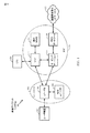
[0045]図1は、LTEネットワークアーキテクチャ100を示す図である。LTEネットワークアーキテクチャ100は、発展型パケットシステム(EPS:Evolved Packet System)100と呼ばれることがある。EPS100は、1つまたは複数のユーザ機器(UE)102と、発展型UMTS地上波無線アクセスネットワーク(E−UTRAN)104と、発展型パケットコア(EPC)110と、ホーム加入者サーバ(HSS)120と、事業者のIPサービス122とを含み得る。EPSは、他のアクセスネットワークと相互接続し得るが、簡単のために、それらのエンティティ/インターフェースは図示されない。図示のように、EPSは、パケット交換サービスを提供するが、当業者が容易に諒解するように、本開示全体にわたって提示される様々な概念は、回線交換サービスを提供するネットワークに拡張され得る。
[0045] FIG. 1 is a diagram illustrating an
[0046]E−UTRANは、発展型ノードB(eノードB)106と、他のeノードB108とを含む。eノードB106は、UE102に対してユーザプレーンプロトコル終端と、制御プレーンプロトコル終端とを提供する。eノードB106は、バックホール(たとえば、X2インターフェース)を介して他のeノードB108に接続され得る。eノードB106は、基地局、トランシーバ基地局、無線基地局、無線トランシーバ、トランシーバ機能、基本サービスセット(BSS:basic service set)、拡張サービスセット(ESS:extended service set)、または何らかの他の好適な用語で呼ばれることもある。eノードB106は、UE102にEPC110へのアクセスポイントを提供する。UE102の例は、セルラーフォン、スマートフォン、セッション開始プロトコル(SIP)電話、ラップトップ、携帯情報端末(PDA)、衛星ラジオ、全地球測位システム、マルチメディアデバイス、ビデオデバイス、デジタルオーディオプレーヤ(たとえば、MP3プレーヤ)、カメラ、ゲーム機、または任意の他の同様の機能デバイスを含む。UE102は、当業者によって、移動局、加入者局、モバイルユニット、加入者ユニット、ワイヤレスユニット、リモートユニット、モバイルデバイス、ワイヤレスデバイス、ワイヤレス通信デバイス、リモートデバイス、モバイル加入者局、アクセス端末、モバイル端末、ワイヤレス端末、リモート端末、ハンドセット、ユーザエージェント、モバイルクライアント、クライアント、または何らかの他の好適な用語で呼ばれることもある。
[0046] The E-UTRAN includes an evolved Node B (
[0047]eノードB106は、たとえば、S1インターフェースを介して、EPC110に接続される。EPC110は、モビリティ管理エンティティ(MME:Mobility Management Entity)112と、他のMME114と、サービングゲートウェイ116と、パケットデータネットワーク(PDN:Packet Data Network)ゲートウェイ118とを含む。MME112は、UE102とEPC110との間のシグナリングを処理する制御ノードである。概して、MME112は、ベアラおよび接続管理を行う。すべてのユーザIPパケットは、サービングゲートウェイ116を通して転送され、サービングゲートウェイ116自体は、PDNゲートウェイ118に接続される。PDNゲートウェイ118は、UEのIPアドレス割振りならびに他の機能を提供する。PDNゲートウェイ118は、通信事業者のIPサービス122に接続される。事業者のIPサービス122は、インターネットと、イントラネットと、IPマルチメディアサブシステム(IMS:IP Multimedia Subsystem)と、PSストリーミングサービス(PSS:PS Streaming Service)とを含み得る。
[0047] The
[0048]図2は、LTEネットワークアーキテクチャにおけるアクセスネットワーク200の一例を示す図である。この例では、アクセスネットワーク200は、いくつかのセルラー領域(セル)202に分割される。1つまたは複数のより低い電力クラスのeノードB208は、セル202のうちの1つまたは複数とオーバーラップするセルラー領域210を有し得る。より低い電力クラスのeノードB208は、リモートラジオヘッド(RRH:remote radio head)、フェムトセル(たとえば、ホームeノードB(HeNB:home eNodeB))、ピコセル、またはマイクロセルであり得る。マクロeノードB204は各々、それぞれのセル202に割り当てられ、セル202の中のすべてのUE206にEPC110へのアクセスポイントを提供するように構成される。アクセスネットワーク200のこの例では集中コントローラはないが、代替構成では集中コントローラが使用され得る。eノードB204は、無線ベアラ制御、承認制御、モビリティ制御、スケジューリング、セキュリティ、およびサービングゲートウェイ116への接続性を含む、すべての無線関係機能を担当する。
[0048] FIG. 2 is a diagram illustrating an example of an
[0049]アクセスネットワーク200によって利用される変調および多元接続方式は、展開されている具体的な電気通信規格に応じて異なり得る。LTE適用例では、周波数分割複信(FDD:frequency division duplexing)と時分割複信(TDD:time division duplexing)の両方をサポートするために、OFDMがダウンリンク上で使用され、SC−FDMAがアップリンク上で使用される。当業者が以下の詳細な説明から容易に諒解するように、本明細書で提示する様々な概念はLTE適用例に好適である。ただし、これらの概念は、他の変調および多元接続技法を採用する他の電気通信規格に容易に拡張され得る。例として、これらの概念は、エボリューションデータオプティマイズド(EV−DO)またはウルトラモバイルブロードバンド(UMB)に拡張され得る。EV−DOおよびUMBは、CDMA2000規格ファミリーの一部として、第3世代パートナーシッププロジェクト2(3GPP2)によって公表されたエアインターフェース規格であり、移動局にブロードバンドインターネットアクセスを提供するためにCDMAを採用する。これらの概念はまた、広帯域CDMA(W−CDMA(登録商標))とTD−SCDMAなどのCDMAの他の変形態とを採用するユニバーサル地上波無線アクセス(UTRA:Universal Terrestrial Radio Access)、TDMAを採用するモバイル通信用グローバルシステム(GSM(登録商標):Global System for Mobile Communications)、ならびに、OFDMAを採用する、発展型UTRA(E−UTRA:Evolved UTRA)、ウルトラモバイルブロードバンド(UMB)、IEEE802.11(Wi−Fi(登録商標))、IEEE802.16(WiMAX(登録商標))、IEEE802.20、およびFlash−OFDMに拡張され得る。UTRA、E−UTRA、UMTS、LTEおよびGSMは、3GPP団体からの文書に記載されている。CDMA2000およびUMBは、3GPP2団体からの文書に記載されている。採用される実際のワイヤレス通信規格および多元接続技術は、特定の適用例およびシステムに課された全体的な設計制約に依存することになる。
[0049] The modulation and multiple access schemes utilized by
[0050]eノードB204は、MIMO技術をサポートする複数のアンテナを有し得る。MIMO技術の使用により、eノードB204は、空間多重化、ビームフォーミング、および送信ダイバーシティをサポートするために空間領域を活用することが可能になる。データの異なるストリームを同じ周波数上で同時に送信するために、空間多重化が使用され得る。データストリームは、データレートを増大させるために単一のUE206に送信されるか、または全体的なシステム容量を増大させるために複数のUE206に送信され得る。これは、各データストリームを空間的にプリコーディングし(すなわち、振幅および位相のスケーリングを適用し)、次いで、ダウンリンク上で複数の送信アンテナを通して空間的にプリコーディングされた各ストリームを送信することによって達成される。空間的にプリコーディングされたデータストリームは、異なる空間シグネチャとともにUE206に到達し、これにより、UE206の各々がそのUE206に宛てられた1つまたは複数のデータストリームを復元することが可能になる。アップリンク上で、各UE206は、空間的にプリコーディングされたデータストリームを送信し、これにより、eノードB204は、空間的にプリコーディングされた各データストリームのソースを識別することが可能になる。
[0050] The
[0051]空間多重化は、概して、チャネル状態が良いときに使用される。チャネル状態があまり好ましくないとき、送信エネルギーを1つまたは複数の方向に集中させるために、ビームフォーミングが使用され得る。これは、複数のアンテナを通した送信のために、データを空間的にプリコーディングすることによって達成され得る。セルの縁部において良好なカバレージを実現するために、送信ダイバーシティと組み合わせてシングルストリームビームフォーミング送信が使用され得る。 [0051] Spatial multiplexing is generally used when channel conditions are good. When channel conditions are less favorable, beamforming can be used to concentrate the transmit energy in one or more directions. This can be achieved by spatially precoding the data for transmission through multiple antennas. Single stream beamforming transmission may be used in combination with transmit diversity to achieve good coverage at the cell edge.
[0052]以下の詳細な説明では、アクセスネットワークの様々な態様が、ダウンリンク上でOFDMをサポートするMIMOシステムを参照しながら説明される。OFDMは、OFDMシンボル内のいくつかのサブキャリアにわたってデータを変調するスペクトル拡散技法である。サブキャリアは、正確な周波数で離間される。離間は、受信機がサブキャリアからデータを復元することを可能にする「直交性」を実現する。時間領域では、OFDMシンボル間干渉をなくすために、ガードインターバル(たとえば、サイクリックプレフィックス)が各OFDMシンボルに追加され得る。アップリンクは、高いピーク対平均電力比(PAPR)を補償するために、SC−FDMAをDFT拡散OFDM信号の形態で使用し得る。 [0052] In the detailed description that follows, various aspects of an access network will be described with reference to a MIMO system supporting OFDM on the downlink. OFDM is a spread spectrum technique that modulates data across several subcarriers within an OFDM symbol. The subcarriers are spaced at a precise frequency. Spacing provides “orthogonality” that allows the receiver to recover data from the subcarriers. In the time domain, a guard interval (eg, a cyclic prefix) may be added to each OFDM symbol to eliminate OFDM intersymbol interference. The uplink may use SC-FDMA in the form of a DFT spread OFDM signal to compensate for high peak-to-average power ratio (PAPR).
[0053]図3は、LTEにおけるダウンリンクフレーム構造の一例を示す図300である。フレーム(10ms)は、等しいサイズの10個のサブフレームに分割され得る。各サブフレームは、2つの連続するタイムスロットを含み得る。2つのタイムスロットを表すためにリソースグリッドが使用され得、各タイムスロットはリソースブロックを含む。リソースグリッドは、複数のリソース要素に分割される。LTEでは、リソースブロックは、周波数領域の中に12個の連続するサブキャリアを含み、各OFDMシンボルの中のノーマルサイクリックプレフィックスについては、時間領域の中に7つの連続するOFDMシンボル、すなわち84個のリソース要素を含む。拡張サイクリックプレフィックスについては、リソースブロックは、時間領域の中に6つの連続するOFDMシンボルを含み、72個のリソース要素をもたらす。R302、304として示されるリソース要素のいくつかは、ダウンリンク基準信号(DL−RS:downlink reference signal)を含む。DL−RSは、(共通RSと呼ばれることもある)セル固有RS(CRS:Cell-specific RS)302と、UE固有RS(UE−RS:UE-specific RS)304とを含む。UE−RS304は、対応する物理ダウンリンク共有チャネル(PDSCH:physical downlink shared channel)がマッピングされるリソースブロック上でのみ送信される。各リソース要素によって搬送されるビット数は、変調方式に依存する。したがって、UEが受信するリソースブロックが多いほど、また変調方式が高いほど、UEのデータレートは高くなる。
[0053] FIG. 3 is a diagram 300 illustrating an example of a downlink frame structure in LTE. A frame (10 ms) may be divided into 10 equally sized subframes. Each subframe may include two consecutive time slots. A resource grid may be used to represent two time slots, each time slot including a resource block. The resource grid is divided into a plurality of resource elements. In LTE, a resource block includes 12 consecutive subcarriers in the frequency domain, and for a normal cyclic prefix in each OFDM symbol, 7 consecutive OFDM symbols in the time domain, i.e., 84. Contains resource elements. For the extended cyclic prefix, the resource block includes 6 consecutive OFDM symbols in the time domain, resulting in 72 resource elements. Some of the resource elements shown as R302, 304 include a downlink reference signal (DL-RS). The DL-RS includes a cell-specific RS (CRS) 302 (also referred to as a common RS) and a UE-specific RS (UE-RS) 304. The UE-
[0054]図4は、LTEにおけるアップリンクフレーム構造の一例を示す図400である。アップリンクのために利用可能なリソースブロックは、データセクションと制御セクションとに区分され得る。制御セクションは、システム帯域幅の2つの縁部において形成され得、構成可能なサイズを有し得る。制御セクションの中のリソースブロックは、制御情報の送信のためにUEに割り当てられ得る。データセクションは、制御セクションの中に含まれないすべてのリソースブロックを含み得る。アップリンクフレーム構造は、連続するサブキャリアを含むデータセクションをもたらし、それによって、データセクションの中の連続するサブキャリアのすべてが単一のUEに割り当てられることを可能にし得る。 [0054] FIG. 4 is a diagram 400 illustrating an example of an uplink frame structure in LTE. Resource blocks available for the uplink may be partitioned into a data section and a control section. The control section may be formed at two edges of the system bandwidth and may have a configurable size. Resource blocks in the control section may be allocated to the UE for transmission of control information. The data section may include all resource blocks that are not included in the control section. The uplink frame structure may result in a data section that includes consecutive subcarriers, thereby allowing all of the consecutive subcarriers in the data section to be assigned to a single UE.
[0055]UEには、eノードBへ制御情報を送信するために、制御セクションの中のリソースブロック410a、410bが割り当てられ得る。UEにはまた、eノードBへデータを送信するために、データセクションの中のリソースブロック420a、420bが割り当てられ得る。UEは、制御セクションの中で割り当てられたリソースブロック上の物理アップリンク制御チャネル(PUCCH:Physical Uplink Control Channel)の中で、制御情報を送信し得る。UEは、データセクションの中で割り当てられたリソースブロック上の物理アップリンク共有チャネル(PUSCH:Physical Uplink Shared Channel)の中で、データのみまたはデータと制御情報の両方を送信し得る。アップリンク送信は、サブフレームの両方のスロットにわたり得、周波数の端から端まででホッピングし得る。
[0055] The UE may be assigned
[0056]初期システムアクセスを実行し、物理ランダムアクセスチャネル(PRACH)430の中でアップリンク同期を達成するために、リソースブロックのセットが使用され得る。PRACH430は、ランダムシーケンスを搬送する。各ランダムアクセスプリアンブルは、6つの連続するリソースブロックに対応する帯域幅を占有する。開始周波数は、ネットワークによって指定される。すなわち、ランダムアクセスプリアンブルの送信は、ある時間リソースおよび周波数リソースに制限される。PRACHに関して、周波数ホッピングはない。PRACH試みは、単一のサブフレーム(1ms)の中で、または少数の隣接するサブフレームのシーケンスの中で搬送され、UEはフレーム(10ms)ごとに単一のPRACH試みのみを行うことができる。 [0056] A set of resource blocks may be used to perform initial system access and achieve uplink synchronization within a physical random access channel (PRACH) 430. PRACH 430 carries a random sequence. Each random access preamble occupies a bandwidth corresponding to six consecutive resource blocks. The starting frequency is specified by the network. That is, transmission of the random access preamble is limited to certain time resources and frequency resources. There is no frequency hopping for PRACH. A PRACH attempt is carried in a single subframe (1 ms) or in a sequence of a few adjacent subframes, and the UE can only make a single PRACH attempt every frame (10 ms) .
[0057]図5は、LTEにおけるユーザプレーンおよび制御プレーンのための無線プロトコルアーキテクチャの一例を示す図500である。UEおよびeノードBのための無線プロトコルアーキテクチャは、3つのレイヤ、すなわち、レイヤ1、レイヤ2、およびレイヤ3とともに示される。レイヤ1(L1レイヤ)は最下位層であり、様々な物理レイヤ信号処理機能を実装する。L1レイヤは、本明細書では物理レイヤ506と呼ばれる。レイヤ2(L2レイヤ)508は、物理レイヤ506の上にあり、物理レイヤ506を介したUEとeノードBとの間のリンクを担当する。
[0057] FIG. 5 is a diagram 500 illustrating an example of a radio protocol architecture for the user plane and control plane in LTE. The radio protocol architecture for the UE and eNodeB is shown with three layers:
[0058]ユーザプレーンでは、L2レイヤ508は、ネットワーク側のeノードBにおいて終端される、媒体アクセス制御(MAC:media access control)サブレイヤ510と、無線リンク制御(RLC:radio link control)サブレイヤ512と、パケットデータコンバージェンスプロトコル(PDCP:packet data convergence protocol)514サブレイヤとを含む。図示されていないが、UEは、L2レイヤ508の上に、ネットワーク側のPDNゲートウェイ118において終端されるネットワークレイヤ(たとえば、IPレイヤ)と、接続の他端(たとえば、遠端UE、サーバなど)において終端されるアプリケーションレイヤとを含む、いくつかの上位レイヤを有し得る。
[0058] In the user plane, the L2 layer 508 is terminated in a network side eNodeB, a medium access control (MAC) sublayer 510, a radio link control (RLC)
[0059]PDCPサブレイヤ514は、様々な無線ベアラと論理チャネルとの間で多重化を提供する。PDCPサブレイヤ514はまた、無線送信オーバーヘッドを低減するための上位レイヤデータパケットに対するヘッダ圧縮と、データパケットを暗号化することによるセキュリティと、UEに対するeノードB間のハンドオーバサポートとを提供する。無線リンク制御(RLC)サブレイヤ512は、上位レイヤデータパケットのセグメンテーションおよびリアセンブリと、紛失データパケットの再送信と、ハイブリッド自動再送要求(HARQ:hybrid automatic repeat request)による、順が狂った受信を補正するためのデータパケットの並べ替えとを提供する。MACサブレイヤ510は、論理チャネルとトランスポートチャネルとの間の多重化を提供する。MACサブレイヤ510はまた、1つのセルの中の様々な無線リソース(たとえば、リソースブロック)をUEの間で割り振ることを担当する。MACサブレイヤ510はまた、HARQ演算を担当する。
[0059] The PDCP sublayer 514 provides multiplexing between various radio bearers and logical channels. The PDCP sublayer 514 also provides header compression for higher layer data packets to reduce radio transmission overhead, security by encrypting data packets, and handover support between eNodeBs for UEs. Radio Link Control (RLC)
[0060]制御プレーンでは、UEおよびeノードBのための無線プロトコルアーキテクチャは、制御プレーンのためのヘッダ圧縮機能がないことを除いて、物理レイヤ506およびL2レイヤ508に対して実質的に同じである。制御プレーンはまた、レイヤ3(L3レイヤ)の中に無線リソース制御(RRC:radio resource control)サブレイヤ516を含む。無線リソース制御(RRC)サブレイヤ516は、無線リソース(すなわち、無線ベアラ)を取得することと、eノードBとUEとの間の無線リソース制御シグナリングを使用して下位レイヤを構成することとを担当する。
[0060] In the control plane, the radio protocol architecture for the UE and eNodeB is substantially the same for the
[0061]図6は、アクセスネットワークの中でUE650と通信するeノードB610のブロック図である。ダウンリンクでは、コアネットワークからの上位レイヤパケットが、コントローラ/プロセッサ675に提供される。コントローラ/プロセッサ675は、L2レイヤの機能を実装する。ダウンリンクでは、コントローラ/プロセッサ675は、様々な優先度メトリックに基づいて、ヘッダ圧縮と、暗号化と、パケットセグメンテーションおよび並べ替えと、論理チャネルとトランスポートチャネルとの間の多重化と、UE650への無線リソース割振りとを提供する。コントローラ/プロセッサ675はまた、HARQ演算と、紛失パケットの再送信と、UE650へのシグナリングとを担当する。
[0061] FIG. 6 is a block diagram of an
[0062]送信プロセッサ616は、L1レイヤ(すなわち、物理レイヤ)のための様々な信号処理機能を実装する。信号処理機能は、UE650における前方誤り訂正(FEC)と、様々な変調方式(たとえば、2位相シフトキーイング(BPSK)、4位相シフトキーイング(QPSK)、M位相シフトキーイング(M−PSK)、多値直交振幅変調(M−QAM))に基づく信号コンスタレーションへのマッピングとを容易にするための、コーディングとインターリービングとを含む。コーディングおよび変調されたシンボルは、次いで、並列ストリームに分割される。各ストリームは、次いで、OFDMサブキャリアにマッピングされ、時間領域および/または周波数領域の中で基準信号(たとえば、パイロット)と多重化され、次いで、逆高速フーリエ変換(IFFT:Inverse Fast Fourier Transform)を使用して互いに合成されて、時間領域OFDMシンボルストリームを搬送する物理チャネルを生成する。OFDMストリームは、複数の空間ストリームを生成するために空間的にプリコーディングされる。チャネル推定器674からのチャネル推定値は、コーディングおよび変調方式を決定するために、ならびに空間処理のために使用され得る。チャネル推定値は、UE650によって送信される基準信号および/またはチャネル状態フィードバックから導出され得る。各空間ストリームは、次いで、別個の送信機618TXを介して、相異なるアンテナ620に供給される。各送信機618TXは、送信のためにそれぞれの空間ストリームを用いてRFキャリアを変調する。
[0062] The transmit processor 616 implements various signal processing functions for the L1 layer (ie, physical layer). Signal processing functions include forward error correction (FEC) in
[0063]UE650において、各受信機654RXは、そのそれぞれのアンテナ652を通して信号を受信する。各受信機654RXは、RFキャリア上に変調されている情報を復元し、受信機プロセッサ656に情報を供給する。受信機プロセッサ656は、L1レイヤの様々な信号処理機能を実装する。受信機プロセッサ656は、UE650に宛てられた任意の空間ストリームを復元するために、情報に対して空間処理を実行する。複数の空間ストリームがUE650に宛てられる場合、それらは受信機プロセッサ656によって単一のOFDMシンボルストリームに合成され得る。受信機プロセッサ656は、次いで、高速フーリエ変換(FFT:Fast Fourier Transform)を使用して、OFDMシンボルストリームを時間領域から周波数領域へ変換する。周波数領域信号は、OFDM信号の各サブキャリアに対して、別個のOFDMシンボルストリームを備える。各サブキャリア上のシンボル、および基準信号は、eノードB610によって送信される、可能性が最も高い信号コンスタレーション点を決定することによって、復元および復調される。これらの軟判定は、チャネル推定器658によって計算されるチャネル推定値に基づき得る。軟判定は、次いで、物理チャネル上でeノードB610によって当初送信されたデータと制御信号とを復元するために、復号およびデインターリーブされる。データおよび制御信号は、次いで、コントローラ/プロセッサ659に供給される。
[0063] At
[0064]コントローラ/プロセッサ659は、L2レイヤを実装する。コントローラ/プロセッサは、プログラムコードとデータとを記憶するメモリ660に関連し得る。メモリ660は、コンピュータ可読媒体と呼ばれることがある。アップリンクでは、コントローラ/プロセッサ659は、コアネットワークからの上位レイヤパケットを復元するために、トランスポートチャネルと論理チャネルとの間の多重分離と、パケットリアセンブリと、復号(deciphering)と、ヘッダ復元(decompression)と、制御信号処理とを提供する。上位レイヤパケットは、次いで、L2レイヤの上のすべてのプロトコルレイヤを表すデータシンク662に供給される。様々な制御信号はまた、L3処理のためにデータシンク662に供給され得る。コントローラ/プロセッサ659はまた、HARQ演算をサポートするために、肯定応答(ACK)および/または否定応答(NACK)プロトコルを使用する誤り検出を担当する。
[0064] The controller / processor 659 implements the L2 layer. The controller / processor may be associated with a memory 660 that stores program codes and data. Memory 660 may be referred to as a computer readable medium. On the uplink, the controller / processor 659 demultiplexes between transport and logical channels, packet reassembly, decoding, and header recovery to recover higher layer packets from the core network. (Decompression) and control signal processing. Upper layer packets are then fed to a
[0065]アップリンクでは、データソース667は、コントローラ/プロセッサ659に上位レイヤパケットを供給するために使用される。データソース667は、L2レイヤの上のすべてのプロトコルレイヤを表す。eノードB610によるダウンリンク送信に関して説明した機能と同様に、コントローラ/プロセッサ659は、ヘッダ圧縮と、暗号化と、パケットセグメンテーションおよび並べ替えと、eノードB610による無線リソース割振りに基づく論理チャネルとトランスポートチャネルとの間の多重化とを提供することによって、ユーザプレーンおよび制御プレーンのためのL2レイヤを実装する。コントローラ/プロセッサ659はまた、HARQ演算と、紛失パケットの再送信と、eノードB610へのシグナリングとを担当する。
[0065] On the uplink, the
[0066]eノードB610によって送信される基準信号またはフィードバックからの、チャネル推定器658によって導出されるチャネル推定値は、適切なコーディングおよび変調方式を選択することと、空間処理を容易にすることとを行うために、TXプロセッサ668によって使用され得る。TXプロセッサ668によって生成される空間ストリームは、別個の送信機654TXを介して相異なるアンテナ652に供給される。各送信機654TXは、送信のためにそれぞれの空間ストリームを用いてRFキャリアを変調する。
[0066] Channel estimates derived by the
[0067]アップリンク送信は、UE650における受信機機能に関して説明した方法と同様の方法で、eノードB610において処理される。各受信機618RXは、そのそれぞれのアンテナ620を通して信号を受信する。各受信機618RXは、RFキャリア上に変調されている情報を復元し、RXプロセッサ670に情報を供給する。RXプロセッサ670は、L1レイヤを実装し得る。
[0067] Uplink transmissions are processed at the
[0068]コントローラ/プロセッサ675は、L2レイヤを実装する。コントローラ/プロセッサ675は、プログラムコードとデータとを記憶するメモリ676に関連し得る。メモリ676は、コンピュータ可読媒体と呼ばれることがある。アップリンクでは、コントローラ/プロセッサ675は、UE650からの上位レイヤパケットを復元するために、トランスポートチャネルと論理チャネルとの間の多重分離と、パケットリアセンブリと、復号と、ヘッダ復元と、制御信号処理とを提供する。コントローラ/プロセッサ675からの上位レイヤパケットは、コアネットワークに提供され得る。コントローラ/プロセッサ675はまた、HARQ演算をサポートするために、ACKおよび/またはNACKプロトコルを使用する誤り検出を担当する。
時分割ロングタームエボリューション(TD−LTE)フレーム構造の修正
[0069]地上波空対地(ATG)システムによる航空機へのインターネット通信のために利用可能なスペクトルは、実際的および経済的理由のために限定される。(米国本土などの)広いエリアにわたって高い高度で飛行する航空機とのシームレス通信を提供することは、広いエリアにわたって利用可能であるスペクトルを必要とする。すなわち、ATGシステムに割り当てられるスペクトルは、全国的に利用可能であるべきである。しかしながら、全国的に利用可能であるスペクトルの部分を識別すること、まして、他の用途のために割り振られるスペクトルのそのような部分を解放するように構成することには問題があった。
[0068] The controller /
Correction of time division long term evolution (TD-LTE) frame structure
[0069] The spectrum available for Internet communication to aircraft by terrestrial air-to-ground (ATG) systems is limited for practical and economic reasons. Providing seamless communication with aircraft flying at high altitudes over large areas (such as the continental United States) requires a spectrum that is available over large areas. That is, the spectrum allocated to the ATG system should be available nationwide. However, it has been problematic to identify portions of the spectrum that are available nationwide, and to free up those portions of the spectrum that are allocated for other uses.
[0070]大量のスペクトルが、ブロードキャストTVおよび双方向固定衛星サービス(FSS)で使用するために静止衛星に割り当てられている。本開示の一態様では、高データレートの航空機対地上通信アンテナシステムが、航空機にインターネットサービスを提供する。 [0070] A large amount of spectrum is allocated to geostationary satellites for use in broadcast TV and interactive fixed satellite service (FSS). In one aspect of the present disclosure, a high data rate aircraft-to-ground communication antenna system provides Internet services to an aircraft.
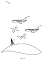
[0071]特に、本開示の態様は、次世代空対地(次世代AG)システムのための方法と装置とを提供する。次世代AGシステムは、衛星システムに対して割り当てられたスペクトルのアップリンク部分を使用し得る、飛行機の中の航空機トランシーバ(AT)と通信する地上基地局(GBS)を含み得る。本開示の例示的な態様による次世代AG通信のためのシステム700が、図7に示される。
[0071] In particular, aspects of the present disclosure provide methods and apparatus for next generation air-to-ground (next generation AG) systems. The next generation AG system may include a ground base station (GBS) that communicates with an aircraft transceiver (AT) in an airplane that may use the uplink portion of the spectrum allocated to the satellite system. A
[0072]この構成では、次世代AGシステム700は、順方向リンク(FL)708−1と逆方向リンク(RL)706−1とを使用して、衛星アップリンクバンド上で信号を送信および受信する地上基地局710を含む。第1の航空機750−1は、航空機アンテナ800と、地上基地局710と通信する航空機トランシーバ(AT)650(図6)とを含む。航空機トランシーバ(AT)650はまた、順方向リンク708−1と返信リンク706−1とを使用して、衛星アップリンクバンド上で信号を受信および送信し得る。この構成では、航空機アンテナ800は、たとえば、図8に示すような、指向性アンテナを含み得る。
[0072] In this configuration, next
[0073]図8は、たとえば、14ギガヘルツ(GHz)において動作する航空機アンテナアレイ802(802−1、...、802−N)を有する航空機アンテナ800の一例を示す。典型的に、航空機アンテナアレイ802−1は、それぞれが方位角において30°セクタをカバーし、約2.0インチ×0.45のインチの開口サイズを有し、>10dBi(dB等方性)の利得を有する、12個のホーンアンテナ804(804−1、...、804−12)を有する。一構成では、アンテナアレイの全径は、ほぼ8インチである。航空機アンテナアレイに関して説明されるが、任意の指向性アンテナが、本開示の態様に従って備えられてよい。本開示の説明される態様は航空機に関して提供されるが、本開示はそれに限定されない。本開示の態様は、地上局と通信する現在または将来の飛行中の物体に適用され得る。
[0073] FIG. 8 illustrates an example of an
[0074]この構成では、航空機アンテナ800は、任意の方位角において地上基地局710と通信できるマルチビーム切替え可能アレイを含む。図7に示すように、航空機アンテナ800は、空気抵抗を低減するかまたは最小限に抑えるために、小さい突出部および空気力学的プロファイルを用いて胴体の下に取り付けられる。一構成では、アンテナの高度カバレージは、たとえば、アンテナ利得を得るためのポインティング方向を与えるために、水平線より下へ約3°〜20°である。航空機アンテナ800は、たとえば、図8に示すように、各素子が異なる方位角において別個のビームを導き、それぞれが360/N度をカバーするように配置されたアレイNの素子を含み得る。
[0074] In this configuration,
[0075]図8は12ビームアレイ構成での航空機アンテナアレイ802を示すが、本開示の範囲内のままでありながら他の構成が可能であることを認識されたい。特に、1つの例示的な構成は、4ビームアレイ構成での4アンテナアレイを含む。別の構成では、指向性アンテナは、本開示の範囲内のままでありながら次世代AGシステム700の一部として備えられてよい。
[0075] Although FIG. 8 shows an aircraft antenna array 802 in a 12 beam array configuration, it should be appreciated that other configurations are possible while remaining within the scope of the present disclosure. In particular, one exemplary configuration includes a four antenna array in a four beam array configuration. In another configuration, a directional antenna may be provided as part of the next
[0076]再び図7を参照すると、第2の航空機750−2は、図6に示すような航空機トランシーバ(AT)650と通信する航空機アンテナ800を有するシステムを含む。航空機アンテナ800は、地上基地局710と通信し、また、順方向リンク708−2と返信リンク706−2とを使用して、衛星アップリンクバンド上で信号を受信および送信する。
[0076] Referring again to FIG. 7, the second aircraft 750-2 includes a system having an
[0077]たとえば、図7に示すような次世代AGシステムは、図6に示すような航空機トランシーバ(AT)650を使用して、飛行している航空機との広帯域接続性を提供し得る。この構成では、航空機トランシーバは、時分割ロングタームエボリューション(TD−LTE)エアインターフェースに従って動作し得る。しかしながら、時分割複信(TDD)端末(たとえば、AT650)では、タイミングアドバンスされるアップリンク送信は、先行するいかなるダウンリンクの受信ともオーバーラップするべきでない。 [0077] For example, a next generation AG system as shown in FIG. 7 may provide broadband connectivity with a flying aircraft using an aircraft transceiver (AT) 650 as shown in FIG. In this configuration, the aircraft transceiver may operate according to a time division long term evolution (TD-LTE) air interface. However, in a time division duplex (TDD) terminal (eg, AT 650), a timing advanced uplink transmission should not overlap with any previous downlink reception.
[0078]たとえば、TD−LTEエアインターフェースは、直交アップリンクセル内多元接続方式に従って動作し得る。この例では、セルの中の異なるUE(たとえば、AT650)からの送信は、アップリンク多元接続の直交性を維持するために、eノードB(たとえば、地上基地局710)の受信機において時間整合される。動作中、タイミングアドバンスが、受信されるダウンリンクタイミングに対してアップリンク送信の時間整合を与えるために、UE送信機において適用され得る。基地局においてタイミングアドバンスを使用することは、異なるUEの間の様々な伝搬遅延を相殺し得る。 [0078] For example, a TD-LTE air interface may operate according to an orthogonal uplink intra-cell multiple access scheme. In this example, transmissions from different UEs (eg, AT 650) in the cell are time aligned at the receiver of the eNode B (eg, terrestrial base station 710) to maintain uplink multiple access orthogonality. Is done. In operation, timing advance may be applied at the UE transmitter to provide time alignment of uplink transmissions for received downlink timing. Using timing advance at the base station may offset various propagation delays between different UEs.
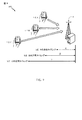
[0079]図9は、UE A、UE BおよびUE Cが基地局910から異なる距離において配置されるブロック図900である。しかしながら、基地局910からの異なる距離は、異なるUEから基地局910への伝搬遅延を変化させることをもたらす。この例では、基地局においてタイミングアドバンス(TA)のシグナリングを実行することによって、UE送信は基地局に到達するときに直交し時間領域において同期される。一般に、基地局におけるタイミングアドバンスの適用は、UE送信をCP(サイクリックプレフィックス)の長さの分数内で同期させる。タイミングアドバンスコマンドは、ベースラインのTD−LTE構成において、0.52マイクロ秒のタイミング分解能で0から最大0.67ミリ秒までを有する媒体アクセス制御(MAC)要素として送られ得る。この例では、基地局910の受信機における時間整合を可能にするために、UE Aはタイミングアドバンス(α)を受信し、UE Bはタイミングアドバンス(β)を受信し、UE Cはタイミングアドバンス(γ)を受信する。 [0079] FIG. 9 is a block diagram 900 where UE A, UE B, and UE C are located at different distances from the base station 910. However, different distances from the base station 910 result in changing the propagation delay from different UEs to the base station 910. In this example, by performing timing advance (TA) signaling at the base station, the UE transmission is orthogonal and synchronized in the time domain when it reaches the base station. In general, application of timing advance at the base station synchronizes the UE transmission within a fraction of the CP (cyclic prefix) length. The timing advance command may be sent as a medium access control (MAC) element having 0 to a maximum of 0.67 milliseconds with a timing resolution of 0.52 microseconds in a baseline TD-LTE configuration. In this example, UE A receives a timing advance (α), UE B receives a timing advance (β), and UE C receives a timing advance (β) to enable time alignment at the receiver of base station 910. γ) is received.
[0080]TD−LTEでは、送信機能/受信機能の間の切替えは、ダウンリンクからアップリンクへ(受信から送信へのUE切替え)およびアップリンクからダウンリンクへ(受信から送信へのeノードB(基地局)切替え)で発生する。LTEアップリンクの直交性を保持するために、eノードBとUEとの間の伝搬遅延はタイミングアドバンスによって補償される。時分割複信(TDD)システムに関して、タイミングアドバンスされるアップリンク送信は、先行するいかなるダウンリンクの受信ともオーバーラップするべきでない。 [0080] In TD-LTE, switching between transmit / receive functions is downlink to uplink (UE switching from reception to transmission) and uplink to downlink (eNode B from reception to transmission). (Base station) switching). In order to preserve the LTE uplink orthogonality, the propagation delay between the eNodeB and the UE is compensated by timing advance. For time division duplex (TDD) systems, timing advanced uplink transmissions should not overlap with any preceding downlink reception.
[0081]TD−LTEエアインターフェースは、ダウンリンク通信とアップリンク通信との間の送信ギャップ(たとえば、ガード期間(GP))を規定することによって、ダウンリンク通信とアップリンク通信との間のオーバーラップを防止し得る。受信(ダウンリンク)と送信(アップリンク)との間のガード期間は、起こり得る最大のタイミングアドバンスと、任意のスイッチング遅延とを収容するように規定され得る。TD−LTEエアインターフェースのタイミングアドバンスは、ラウンドトリップ伝搬遅延の関数である。加えて、TD−LTEエアインターフェースのアップリンク−ダウンリンクサイクルのための総ガード時間は、セルによってサポートされる最悪のラウンドトリップ伝搬遅延よりも長くあり得る。 [0081] The TD-LTE air interface defines an over-transmission between downlink and uplink communications by defining a transmission gap (eg, guard period (GP)) between downlink and uplink communications. Wrap can be prevented. A guard period between reception (downlink) and transmission (uplink) may be defined to accommodate the maximum possible timing advance and any switching delay. The timing advance of the TD-LTE air interface is a function of the round trip propagation delay. In addition, the total guard time for the uplink-downlink cycle of the TD-LTE air interface may be longer than the worst round trip propagation delay supported by the cell.
[0082]図10は、UE1050のダウンリンク通信1008−2とアップリンク通信1006−2との間のオーバーラップを防止するように、eノードBのダウンリンク通信1008−1とアップリンク通信1006−1との間のガード期間(TGP)1012が選択されるタイミング図1000である。オーバーラップを防止するために、ガード期間(TGP)は、ラウンドトリップ伝搬遅延(2TP)と、UE1050における受信対送信切替え遅延(TUE-Rx-Tx)1016の両方を上回るべきであり、ここで、TPは一方向の伝搬遅延を示す。たとえば、ガード期間(TGP)は、次式を与えて計算され得る。 [0082] FIG. 10 shows eNodeB downlink communication 1008-1 and uplink communication 1006- so as to prevent overlap between UE 1050 downlink communication 1008-2 and uplink communication 1006-2. 1 is a timing diagram 1000 in which a guard period (T GP ) 1012 between 1 and 1 is selected. In order to prevent overlap, the guard period (T GP ) should exceed both the round trip propagation delay (2T P ) and the receive-to-transmit switch delay (T UE-Rx-Tx ) 1016 at UE 1050, here, T P denotes a one-way propagation delay. For example, the guard period (T GP ) can be calculated given by:

[0083]しかしながら、3GPP LTE規格は、約0.72ミリ秒としてのガード期間の継続時間に限定される。このガード期間の継続時間は、最大100キロメートルのセル半径を前提とする。しかしながら、次世代AGシステムでは、より大きいセルサイズ(たとえば、250〜350キロメートルのセル半径)が規定され得る。 [0083] However, the 3GPP LTE standard is limited to a guard period duration of about 0.72 milliseconds. The duration of this guard period assumes a cell radius of up to 100 kilometers. However, in a next generation AG system, a larger cell size (eg, a cell radius of 250-350 kilometers) may be defined.
[0084]図11は、eノードB1010のダウンリンク通信1008−1とアップリンク通信1006−1との間のガード期間の継続時間(TGP)1112が不十分であり、UE1050のダウンリンク通信1008−2とアップリンク通信1006−2との間のオーバーラップ1120をもたらすタイミング図1100である。その結果、3GPP定義のTDDフレーム構造を使用することは、次世代AGシステム内でのアップリンク−ダウンリンクのオーバーラップならびに著しい信号劣化およびデータ損失につながる。
[0084] FIG. 11 shows that the guard period duration (T GP ) 1112 between eNode B 1010 downlink communication 1008-1 and uplink communication 1006-1 is insufficient, and UE 1050 downlink communication 1008 2 is a timing diagram 1100 that provides an
[0085]本開示の一態様では、次世代AGシステム構造のエアインターフェースによって使用されるフレームが修正される。一構成では、200〜250キロメートル程度のセル半径をサポートするために、2ミリ秒の特殊サブフレームを有するTD−LTEフレーム構造が規定される。別の構成では、300〜350キロメートル程度のセル半径をサポートするために、3ミリ秒の特殊サブフレームを有するTD−LTEフレーム構造が規定される。さらなる構成では、ネストされた(nested)フレーム構造が、異なるアップリンク−ダウンリンクサブフレーム構成の間の共存をもたらす。本開示の一態様では、エアセルは、基地局(たとえば、eノードB610)までの距離に基づいて、複数のゾーンへカテゴリー化される。本開示のこの態様では、異なるラウンドトリップ伝搬遅延に対応する異なるアップリンク/ダウンリンクサブフレーム構成が、複数のゾーンの各々との通信を収容するために使用される。 [0085] In one aspect of the present disclosure, the frame used by the air interface of the next generation AG system structure is modified. In one configuration, a TD-LTE frame structure with a special subframe of 2 milliseconds is defined to support a cell radius on the order of 200-250 kilometers. In another configuration, a TD-LTE frame structure with a special subframe of 3 milliseconds is defined to support a cell radius on the order of 300-350 kilometers. In a further configuration, a nested frame structure provides coexistence between different uplink-downlink subframe configurations. In one aspect of the present disclosure, air cells are categorized into multiple zones based on distance to a base station (eg, eNodeB 610). In this aspect of the present disclosure, different uplink / downlink subframe configurations corresponding to different round trip propagation delays are used to accommodate communication with each of the multiple zones.
[0086]ネストされたフレーム構造は、飛行中の物体があるゾーンから別のゾーンへ移動するとき、動的な変更を可能にする。たとえば、ネストされたフレーム構造は、各ゾーンの中で様々な特殊サブフレーム長の間の動的な切替えを可能にする。この動的な切替えは、呼における中断を伴って、または伴わずに実現され得る。呼を中断することなく実現されるとき、ネストされたフレーム構造は、動的なフレーム構造になる。一構成では、UEがエアセルの差分ゾーン(たとえば、図23のゾーン0、ゾーン1およびゾーン2)の間で移動するとき、ネストされたフレーム構造は、非拡張特殊サブフレーム、第1の拡張特殊サブフレームおよび第2の拡張特殊サブフレームの間で動的に変化する。
[0086] Nested frame structures allow for dynamic changes as objects in flight move from one zone to another. For example, the nested frame structure allows dynamic switching between various special subframe lengths within each zone. This dynamic switching may be achieved with or without interruption in the call. When implemented without interrupting calls, the nested frame structure becomes a dynamic frame structure. In one configuration, when the UE moves between air cell differential zones (eg,
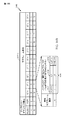
[0087]図12は、従来のTD−LTE無線フレーム構造1200を示すブロック図である。典型的に、従来のTD−LTE無線フレーム構造1200は、サブフレーム番号1230と、アップリンク−ダウンリンク構成列1232と、ダウンリンク対アップリンク切替え点周期性列1234とを含む。この例では、TD−LTE無線フレーム構造は、10ミリ秒にわたり、10個の1ミリ秒サブフレーム(SF0、...、SF9)からなる。様々なサブフレームが、ダウンリンク(D)サブフレーム、アップリンク(U)サブフレームまたは特殊(S)サブフレームとして構成され得る。この例では、SF1は7個(0、...、6)のアップリンク−ダウンリンク構成の各々の中で特殊サブフレームとして構成され、SF6はアップリンク−ダウンリンク構成0、1、2および6の中で特殊サブフレームとして構成される。
[0087] FIG. 12 is a block diagram illustrating a conventional TD-LTE
[0088]特殊サブフレーム1240は、ダウンリンク通信とアップリンク通信との間の切替え点として働く。特殊サブフレーム1240は、ダウンリンクパイロットタイムスロット(DwPTS)部分1242と、ガード期間(GP)部分1244と、アップリンクパイロットタイムスロット(UpPTS)部分1246とを含む。動作中、特殊サブフレーム1240のDwPTS部分1242は、通常の、ただし短縮されたダウンリンクサブフレームとして扱われ得る。DwPTS部分1242は、通常、基準信号(RS)と、制御情報と、1次同期信号(PSS)とを含む。DwPTS部分はまた、データ送信を搬送し得る。特殊サブフレーム1240のUpPTS部分1246は、サウンディング(sounding)基準信号(たとえば、1シンボル長)、または小さいセルサイズ用の特殊な(ランダムアクセスチャネル(RACH)(たとえば、2シンボル長)のいずれかのために使用され得る。
[0088]
[0089]図12に示すように、特殊サブフレーム1240のGP部分1244は、ダウンリンク通信とアップリンク通信との間の切替え点を提供する。特殊サブフレーム1240のGP部分1244の長さは、サポート可能な最大セルサイズを決定する際の要因のうちの1つである。この例では、GP部分1244の最大長は、
[0089] As shown in FIG. 12, the GP portion 1244 of the
である。 It is.
[0090]図13は、ノーマルサイクリックプレフィックス(CP)に基づく様々な特殊サブフレーム構成による特殊サブフレームのコンポーネント長を示す表1300である。表1300は、特殊サブフレーム構成列1332、コンポーネント長列1336内のDwPTS列1342、GP列1344およびUpPTS列1346を含む。この例では、コンポーネント長は、直交周波数分割多重(OFDM)シンボルを単位として示される。
[0090] FIG. 13 is a table 1300 illustrating component lengths of special subframes with various special subframe configurations based on normal cyclic prefix (CP). Table 1300 includes a special
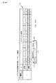
[0091]図14は、構成インデックス1432およびサブフレーム番号1430に基づくTD−LTE無線フレーム構造1400のサブフレーム内の同期チャネルおよびブロードキャストチャネルの時間領域リソース割振りを示す。この例では、1次同期信号(PSS)は、サブフレーム1およびサブフレーム6の第3のOFDMシンボル(たとえば、5ミリ秒ごとのダウンリンクサブフレーム、または特殊サブフレームのDwPTS部分のいずれか)内に割り振られる。2次同期信号(SSS)は、サブフレーム0およびサブフレーム5の最後のOFDMシンボル(たとえば、5ミリ秒ごとのダウンリンクサブフレーム)内に割り振られる。物理ブロードキャストチャネル(PBCH)は、サブフレーム0のOFDMシンボル7〜10内に(たとえば、10ミリ秒ごとに)割り振られる。タイプ1のシステム情報ブロック(SIB1)は、サブフレーム5(たとえば、偶数無線フレーム)内に割り振られる。
[0091] FIG. 14 shows time domain resource allocation of synchronization and broadcast channels within a subframe of a TD-LTE
[0092]本開示の一態様では、次世代AGシステム構造のエアインターフェースによって使用される無線フレーム構造は、より大きいセル半径を収容するように修正される。言及したように、TD−LTEエアインターフェースは、ダウンリンク通信とアップリンク通信との間の送信ギャップ(たとえば、ガード期間(GP))を規定することによって、アップリンク通信とダウンリンク通信との間のオーバーラップを防止し得る。しかしながら、3GPP LTE規格は、0.714ミリ秒程度のガード期間の継続時間に限定される(式(2)を参照)。このガード期間の継続時間は、最大100キロメートルのセル半径を前提とする。しかしながら、次世代AGシステムでは、より大きいセルサイズ(たとえば、250〜350キロメートルのセル半径)が規定される。 [0092] In one aspect of the present disclosure, the radio frame structure used by the air interface of the next generation AG system structure is modified to accommodate a larger cell radius. As mentioned, the TD-LTE air interface is defined between the uplink and downlink communications by defining a transmission gap (eg, guard period (GP)) between the downlink and uplink communications. Can be prevented from overlapping. However, the 3GPP LTE standard is limited to a guard period duration of about 0.714 milliseconds (see equation (2)). The duration of this guard period assumes a cell radius of up to 100 kilometers. However, in the next generation AG system, a larger cell size (eg, a cell radius of 250-350 kilometers) is defined.
[0093]本開示の一態様では、特殊サブフレームは、大きいラウンドトリップ遅延(RTD)を有するダウンリンクからアップリンクへの切替えを可能にするように再設計される。図10に上述するように、オーバーラップは、ラウンドトリップ伝搬遅延(2TP)と、UE1050における受信対送信切替え遅延(TUE-Rx-Tx)1016とを上回るガード期間(TGP)を規定することによって防止され、ここで、TPは一方向の伝搬遅延を示す。ガード期間(TGP)は、式(1)に従って計算され得る。たとえば、250キロメートル(km)の伸張されたセル半径を仮定すると、航空機がセル縁部にあるときのラウンドトリップ伝搬遅延は、 [0093] In one aspect of the present disclosure, special subframes are redesigned to allow downlink to uplink switching with large round trip delay (RTD). As described above in FIG. 10, the overlap defines a guard period (T GP ) that exceeds the round trip propagation delay (2T P ) and the receive-to-transmit switch delay (T UE-Rx-Tx ) 1016 at UE 1050. Where TP denotes a one-way propagation delay. The guard period (T GP ) can be calculated according to equation (1). For example, assuming a stretched cell radius of 250 kilometers (km), the round trip propagation delay when the aircraft is at the cell edge is
によって与えられる。
350キロメートル(km)の伸張されたセル半径を仮定すると、航空機がセル縁部にあるときのラウンドトリップ伝搬遅延は、
Given by.
Assuming an extended cell radius of 350 kilometers (km), the round trip propagation delay when the aircraft is at the cell edge is
によって与えられる。 Given by.
[0094]しかしながら、3GPP LTE規格は、最大100キロメートルのセル半径をサポートするために、より短いガード期間の継続時間(たとえば、0.714ミリ秒)に限定される。式(1)に基づいて、250キロメートルのセル半径に対して、ガード期間は次のように計算される。 [0094] However, the 3GPP LTE standard is limited to shorter guard period durations (eg, 0.714 milliseconds) to support a cell radius of up to 100 kilometers. Based on equation (1), for a cell radius of 250 kilometers, the guard period is calculated as follows:
350キロメートルのセル半径に対して、ガード期間は次のように計算される。 For a cell radius of 350 kilometers, the guard period is calculated as follows:
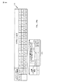
[0095]図15は、本開示の一態様による修正された無線フレーム構造1500を示すブロック図である。修正された無線フレーム構造1500のこの構成は、図14に示す3GPP同期/ブロードキャストチャネル構造を維持する。この構成では、サブフレーム0、1、5および6は、1次同期信号(PSS)、2次同期信号(SSS)、ブロードキャスト制御チャネル(BCCH)、動的ブロードキャストチャネル(D−BCH)、およびタイプ1のシステム情報ブロック(SIB1)の送信を許容するための、ダウンリンクまたは特殊サブフレームのいずれかである。図14に示す3GPP同期/ブロードキャストチャネル構造を維持することは、複雑なハードウェア変更を回避する。
[0095] FIG. 15 is a block diagram illustrating a modified
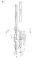
[0096]図16Aは、250キロメートル程度の第1の拡張セル半径をサポートするための、第1の拡張された特殊サブフレーム(たとえば、2ミリ秒)を有するTD−LTE無線フレーム構造の一構成を示すブロック図である。フレーム構造1600は、サブフレーム1およびサブフレーム2にわたって延びる拡張された特殊サブフレーム1650を含む、10ミリ秒の周期性を有する。このフレーム構造1600は、構成インデックス1632によって言及されるように、次世代AGシステム構成AおよびBをサポートする。この構成では、次世代AGシステム構成Aは、図12に示すように、アップリンク−ダウンリンク構成0に基づく。加えて、次世代AGシステム構成Bは、図12に示すような、アップリンク−ダウンリンク構成3に基づく。
[0096] FIG. 16A shows one configuration of a TD-LTE radio frame structure with a first extended special subframe (eg, 2 milliseconds) to support a first extended cell radius on the order of 250 kilometers. FIG.
[0097]図16Bは、図16Aに示す拡張された特殊サブフレーム1650の形成を可能にするように修正された特殊サブフレーム1640をさらに示す。修正された特殊サブフレーム1640は、ダウンリンクパイロットタイムスロット(DwPTS)部分1642と、ガード期間(GP)部分1644とを含む。アップリンクパイロットタイムスロット(UpPTS)部分1646および隣接するアップリンクサブフレーム(たとえば、SF2および/またはSF7)は、ガード期間(GP)部分1644を延ばして拡張された特殊サブフレーム1650を形成するために省略(ミュート)される(図16A)。たとえば、ガード期間(GP)部分1644は、ノーマルサイクリックプレフィックスが使用されるのか、または拡張サイクリックプレフィックスが使用されるのかに応じて、25OFDMシンボル長(たとえば、1.785ms)を形成するように、ミュートされた隣接するアップリンクサブフレーム(たとえば、SF2、SF7およびSF12)のGP部分と組み合わされ得る。この構成では、修正された特殊サブフレーム1640のDwPTS部分1642は、通常の、ただし短縮されたダウンリンクサブフレームとして扱われる。たとえば、DwPTS部分1642は、基準信号(RS)、制御情報、1次同期信号(PSS)などを送信するために使用される、3OFDMシンボル長を有し得る。
[0097] FIG. 16B further illustrates a
[0098]この構成では、UpPTS部分1646をミュートしている間、特殊サブフレーム構成0が適用される。たとえば、UpPTS部分1646は、いかなるサウンディング基準信号もスケジューリングしないことによってミュートされ得る。次世代AGシステム構成Bでは、特殊サブフレーム1に隣接するアップリンクサブフレーム2は、2ミリ秒の拡張された特殊サブフレームとして、拡張された特殊サブフレーム1650を形成するためにミュートされる。この例では、アップリンクサブフレーム2は、アップリンクサブフレーム2の間にいかなるアップリンクデータ送信もスケジューリングしないことによってミュートされる。アップリンクサブフレーム2をミュートすることはまた、肯定応答(ACK)/否定応答(NACK)フィードバックを次の適当なサブフレームへ移すことを伴ってよい。同様に、いかなるチャネル品質情報(CQI)、プリコーディング行列インジケータ、および/またはランクインジケータ情報も、アップリンクサブフレーム2の間に報告されない。加えて、アップリンクサブフレーム2の間に、サウンディング基準信号(SRS)は実行されず、スケジューリング要求(SR)および/または物理ランダムアクセスチャネル(PRACH)送信が実行される。次世代AGシステム構成Aでは、特殊サブフレーム1に隣接するアップリンクサブフレーム2と、特殊サブフレーム6に隣接するアップリンクサブフレーム7の両方は、拡張された特殊サブフレーム1650を形成するためにミュートされる。
[0098] In this configuration,
[0099]図17Aは、第1の拡張セル半径(たとえば、200〜250キロメートル)をサポートするために、同様に規定される第1の拡張された特殊サブフレーム(たとえば、2ミリ秒)を有するTD−LTEフレーム構造1700の別の構成を示す。TD−LTEフレーム構造1700は、特殊サブフレーム1およびアップリンクサブフレーム2にわたって延びる拡張された特殊サブフレーム1750を伴って、20ミリ秒の周期性を有する。この構成では、拡張された特殊サブフレーム1750は、ダウンリンクパイロットタイムスロット(DwPTS)部分1752と、拡張されたガード期間(GP)部分1754とを含む。このTD−LTEフレーム構造1700は、構成インデックス1732によって言及されるように、次世代AGシステム構成Cをサポートする。この構成では、次世代AGシステム構成Cは、図12に示すように、アップリンク−ダウンリンク構成0とアップリンク−ダウンリンク構成3との間で動的に切り替わる。たとえば、偶数サブフレームは、アップリンク−ダウンリンク構成0を使用し得、奇数サブフレームは、アップリンク−ダウンリンク構成3を使用し得る。
[0099] FIG. 17A has a first extended special subframe (eg, 2 milliseconds) that is similarly defined to support a first extended cell radius (eg, 200-250 kilometers). 7 shows another configuration of a TD-
[00100]図17Bは、図17Aに示す拡張された特殊サブフレーム1750の形成を可能にするように修正された特殊サブフレーム1740をさらに示す。修正された特殊サブフレーム1740は、ダウンリンクパイロットタイムスロット(DwPTS)部分1742と、ガード期間(GP)部分1744とを含む。アップリンクパイロットタイムスロット(UpPTS)部分1746および隣接するアップリンクサブフレーム(たとえば、SF2、SF7および/またはSF12)は、ガード期間(GP)部分1744を延ばして拡張された特殊サブフレーム1750を形成するために省略(たとえば、ミュート)される(図17A)。この構成では、修正された特殊サブフレーム1740のDwPTS部分1742は、通常の、ただし短縮されたダウンリンクサブフレームとして扱われる。たとえば、DwPTS部分1742は、基準信号(RS)、制御情報、1次同期信号(PSS)などを送信するための、3OFDMシンボル長を有し得る。この例では、ガード期間(GP)部分1744は、25OFDMシンボル長(たとえば、1.785ms)を形成するように、ミュートされた隣接するアップリンクサブフレーム(たとえば、SF2、SF7およびSF12)のGP部分と組み合わされ得る。一構成では、約1.67ミリ秒としての最大タイミングアドバンスが、通信を同期させるために基地局(たとえば、eノードB610)において適用される。
[00100] FIG. 17B further illustrates a
[00101]この構成では、UpPTS部分1746をミュートしている間、特殊サブフレーム構成0も適用される。UpPTS部分1746は、いかなるサウンディング基準信号もスケジューリングしないことによってミュートされ得る。たとえば、特殊サブフレーム1に隣接するアップリンクサブフレーム2は、2ミリ秒の拡張された特殊サブフレームとして、拡張された特殊サブフレーム1750を形成するためにミュートされる。アップリンクサブフレーム2は、アップリンクサブフレーム2の間にいかなるアップリンクデータ送信もスケジューリングしないことによってミュートされ得る。アップリンクサブフレーム2をミュートすることはまた、任意の肯定応答(ACK)/否定応答(NACK)フィードバックを次の適当なサブフレームへ移すことを伴ってよい。同様に、いかなるチャネル品質情報(CQI)、プリコーディング行列インジケータ、および/またはランクインジケータ情報も、アップリンクサブフレーム2の間に報告されない。加えて、アップリンクサブフレーム2の間に、サウンディング基準信号(SRS)は実行されず、スケジューリング要求(SR)および/または物理ランダムアクセスチャネル(PRACH)送信が実行される。
[00101] In this configuration,
[00102]図18Aは、300〜350キロメートル程度の第2の拡張セル半径をサポートするために規定される第2の拡張された特殊サブフレーム(たとえば、3ミリ秒)を有するTD−LTEフレーム構造1800の別の構成を示す。TD−LTEフレーム構造1800は、サブフレーム1、サブフレーム2およびサブフレーム3にわたって延びる拡張された特殊サブフレーム185を伴って、10ミリ秒の周期性を有する。この構成では、拡張された特殊サブフレーム1850は、ダウンリンクパイロットタイムスロット(DwPTS)部分1852と、拡張されたガード期間(GP)部分1854とを含む。このTD−LTEフレーム構造1800は、構成インデックス1832によって言及されるように、次世代AGシステム構成DおよびEをサポートする。この構成では、次世代AGシステム構成Dは、図12に示すように、アップリンク−ダウンリンク構成0に基づく。加えて、次世代AGシステム構成Eは、図12に示すように、アップリンク−ダウンリンク構成3に基づく。
[00102] FIG. 18A shows a TD-LTE frame structure with a second extended special subframe (eg, 3 milliseconds) defined to support a second extended cell radius on the order of 300-350 kilometers. 1800 shows another configuration. The TD-
[00103]図18Bは、図18Aに示す拡張された特殊サブフレーム1850の形成を可能にするように修正された特殊サブフレーム1840を示す。修正された特殊サブフレーム1840はまた、ダウンリンクパイロットタイムスロット(DwPTS)部分1842と、ガード期間(GP)部分1844とを含む。アップリンクパイロットタイムスロット(UpPTS)部分1846および2つの連続し隣接するアップリンクサブフレーム(たとえば、SF2およびSF3、SF7およびSF8)は、ガード期間(GP)部分1844を延ばして拡張された特殊サブフレーム1850を形成するために省略(たとえば、ミュート)される(図18A)。たとえば、ガード期間(GP)部分1844は、39OFDMシンボル長(たとえば、2.72ミリ秒)を形成するように、ミュートされた隣接するアップリンクサブフレーム(たとえば、SF2およびSF3、SF7およびSF8)のGP部分と組み合わされ得る。この構成では、修正された特殊サブフレーム1840のDwPTS部分1842はまた、通常の、ただし短縮されたダウンリンクサブフレームとして扱われる。たとえば、DwPTS部分1842は、基準信号(RS)、制御情報、1次同期信号(PSS)などを送信するための、3OFDMシンボル長を有し得る。
[00103] FIG. 18B shows a
[00104]この構成では、UpPTS部分1846をミュートしている間、特殊サブフレーム構成0も適用される。この例では、UpPTS部分1846は、いかなるサウンディング基準信号もスケジューリングしないことによってミュートされる。典型的に、特殊サブフレーム1に隣接するアップリンクサブフレーム2およびアップリンクサブフレーム3は、3ミリ秒の拡張された特殊サブフレームとして、拡張された特殊サブフレーム1850を形成するためにミュートされる。この例では、アップリンクサブフレーム2およびアップリンクサブフレーム3は、アップリンクサブフレーム2および3の間にいかなるアップリンクデータ送信もスケジューリングしないことによってミュートされる。アップリンクサブフレーム2および3をミュートすることはまた、任意の肯定応答(ACK)/否定応答(NACK)フィードバックを次の適当なサブフレームへ移すことを伴ってよい。同様に、いかなるチャネル品質情報(CQI)、プリコーディング行列インジケータ、および/またはランクインジケータ情報も、アップリンクサブフレーム2および3の間に報告されない。加えて、アップリンクサブフレーム2および3の間に、サウンディング基準信号(SRS)は実行されず、スケジューリング要求(SR)および/または物理ランダムアクセスチャネル(PRACH)送信が実行される。
[00104] In this configuration,
[00105]図19Aは、第2の拡張セル半径(たとえば、350〜400キロメートル)をサポートするために規定される3ミリ秒の特殊サブフレームを有するTD−LTEフレーム構造1900の別の構成を示す。TD−LTEフレーム構造1900は、サブフレーム1〜3、6〜8および11〜13にわたって延びる拡張された特殊サブフレーム1950を伴って、20ミリ秒の周期性を有する。この構成では、拡張された特殊サブフレーム1950は、ダウンリンクパイロットタイムスロット(DwPTS)部分1952と、拡張されたガード期間(GP)部分1954とを含む。このTD−LTEフレーム構造1900は、構成インデックス1932によって言及されるように、次世代AGシステム構成Fをサポートする。この構成では、次世代AGシステム構成Fは、図12に示すように、アップリンク−ダウンリンク構成0とアップリンク−ダウンリンク構成3との間で動的に切り替わる。たとえば、偶数サブフレームは、アップリンク−ダウンリンク構成0を使用し得、奇数サブフレームは、アップリンク−ダウンリンク構成3を使用し得る。
[00105] FIG. 19A shows another configuration of a TD-
[00106]図19Bは、図19Aに示す拡張された特殊サブフレーム1950の形成を可能にするように修正された特殊サブフレーム1940を示す。修正された特殊サブフレーム1940は、ダウンリンクパイロットタイムスロット(DwPTS)部分1942と、ガード期間(GP)部分1944とを含む。アップリンクパイロットタイムスロット(UpPTS)部分1946および2つの連続し隣接するアップリンクサブフレーム(たとえば、SF2およびSF3、SF7およびSF8、SF12およびSF13)は、ガード期間(GP)部分1944を延ばして拡張された特殊サブフレーム1950を形成するために省略(たとえば、ミュート)される(図19A)。この構成では、修正された特殊サブフレーム1940のDwPTS部分1942は、通常の、ただし短縮されたダウンリンクサブフレームとして扱われる。たとえば、DwPTS部分1942は、基準信号(RS)、制御情報、1次同期信号(PSS)などを送信するために使用される、3OFDMシンボル長を有し得る。この例では、ガード期間(GP)部分1944は、39OFDMシンボル長(たとえば、2.72ミリ秒)を形成するように、ミュートされた隣接するアップリンクサブフレーム(たとえば、SF2およびSF3、SF7およびSF8、SF12およびSF13)のGP部分と組み合わされ得る。一構成では、約2.66ミリ秒としての最大タイミングアドバンスが、通信を同期させるために基地局(たとえば、eノードB610)において適用される。
[00106] FIG. 19B shows a
[00107]この構成では、UpPTS部分1946をミュートしている間、特殊サブフレーム構成0も適用される。UpPTS部分1946は、いかなるサウンディング基準信号もスケジューリングしないことによってミュートされ得る。たとえば、特殊サブフレーム1に隣接するアップリンクサブフレーム2および3は、3ミリ秒の拡張された特殊サブフレームとして、拡張された特殊サブフレーム1950を形成するためにミュートされる。加えて、アップリンクサブフレーム7および8ならびにアップリンクサブフレーム12および13は、ミュートされる。アップリンクサブフレーム2および3、7および8、ならびに12および13は、これらのアップリンクサブフレームの間にいかなるアップリンクデータ送信もスケジューリングしないことによってミュートされ得る。これらのアップリンクサブフレームをミュートすることはまた、任意の肯定応答(ACK)/否定応答(NACK)フィードバックを次の適当なサブフレームへ移すことを伴ってよい。同様に、いかなるチャネル品質情報(CQI)、プリコーディング行列インジケータ、および/またはランクインジケータ情報も、これらのアップリンクサブフレームの間に報告されない。加えて、これらのアップリンクサブフレームの間に、サウンディング基準信号(SRS)は実行されず、スケジューリング要求(SR)および/または物理ランダムアクセスチャネル(PRACH)送信が実行される。
[00107] In this configuration,
[00108]図20は、第1の拡張セル半径をサポートするための次世代AGシステム構成と関連したガード時間オーバーヘッドの表2000であり、第2のものは、従来の(非拡張)セル半径と比較してセル半径を延ばす。上述のように、3GPP LTE規格は、約0.72ミリ秒(たとえば、10OFDMシンボル)ガード時間継続時間に限定される。このガード期間の継続時間は、本明細書で非拡張セル半径と呼ばれる最大100キロメートルのセル半径を前提とする。しかしながら、次世代AGシステムでは、拡張セル半径(たとえば、250〜350キロメートルのセル半径)が規定される。第1の拡張セル半径(たとえば、250キロメートル)用のガード時間は、約1.78ミリ秒(たとえば、25OFDMシンボル)である。第2の拡張セル半径(たとえば、350キロメートル)用のガード時間は、約2.72ミリ秒(たとえば、39OFDMシンボル)である。 [00108] FIG. 20 is a table 2000 of guard time overhead associated with a next generation AG system configuration to support a first extended cell radius, the second being a conventional (non-extended) cell radius and The cell radius is increased by comparison. As mentioned above, the 3GPP LTE standard is limited to a guard time duration of about 0.72 milliseconds (eg, 10 OFDM symbols). The duration of this guard period assumes a cell radius of up to 100 kilometers, referred to herein as a non-extended cell radius. However, in the next generation AG system, an extended cell radius (for example, a cell radius of 250 to 350 kilometers) is defined. The guard time for the first extended cell radius (eg, 250 kilometers) is approximately 1.78 milliseconds (eg, 25 OFDM symbols). The guard time for the second extended cell radius (eg, 350 kilometers) is approximately 2.72 milliseconds (eg, 39 OFDM symbols).
[00109]表2000は、ガード時間(GT)オーバーヘッド列によって言及されるように、拡張セル半径をサポートすることが、低減されたシステムスループットをもたらすことを示す。ガード時間オーバーヘッドに起因するシステムスループット損失は、カバレージ範囲に比例する(1:2.5:3.5)。拡張セル半径をサポートすることは、システムスループットと、アップリンク/ダウンリンクの公平性(DL対UL比列を参照)と、実装複雑さとの間のトレードオフを伴う。表2000は、次世代AGシステム構成BおよびFは、より小さいガード時間オーバーヘッドを有するが、ダウンリンクフロー/アップリンクフローの比が不均衡であることを示す。加えて、複雑さは、10ミリ秒の周期性を有する拡張された特殊サブフレームを実施することと、20ミリ秒の周期性を有する拡張された特殊サブフレームを実施することの間で変化する。表2000のDL対UL比列が、特殊サブフレームの中のDwPTSを含まないことに留意されたい。 [00109] Table 2000 shows that supporting an extended cell radius, as noted by the guard time (GT) overhead sequence, results in reduced system throughput. System throughput loss due to guard time overhead is proportional to the coverage range (1: 2.5: 3.5). Supporting an extended cell radius involves a tradeoff between system throughput, uplink / downlink fairness (see DL to UL ratio sequence), and implementation complexity. Table 2000 shows that the next generation AG system configurations B and F have smaller guard time overhead, but the ratio of downlink flow / uplink flow is unbalanced. In addition, the complexity varies between implementing an extended special subframe with a periodicity of 10 milliseconds and implementing an extended special subframe with a periodicity of 20 milliseconds. . Note that the DL to UL ratio sequence in Table 2000 does not include DwPTS in the special subframe.
[00110]さらなる構成では、ネストされたフレーム構造は、異なるアップリンク−ダウンリンクサブフレーム構成の間の共存をもたらす。本開示の一態様では、エアセルは、基地局(たとえば、eノードB610)までの距離に基づいて、複数のゾーンへカテゴリー化され得る。本開示のこの態様は、異なるラウンドトリップ伝搬遅延に対応する異なるアップリンク/ダウンリンクサブフレーム構成が、複数のゾーンの各々との通信を収容するために使用され得る。 [00110] In a further configuration, the nested frame structure provides coexistence between different uplink-downlink subframe configurations. In one aspect of the present disclosure, an air cell may be categorized into multiple zones based on distance to a base station (eg, eNodeB 610). This aspect of the present disclosure may use different uplink / downlink subframe configurations corresponding to different round trip propagation delays to accommodate communication with each of multiple zones.
[00111]図21は、本開示の一態様による、拡張セル半径をサポートするための、複数のゾーンへのエアセル2100のカテゴリー化を示す。この構成では、エアセル2100は、基地局(たとえば、eノードB)から80〜100キロメートルよりも近い航空機トランシーバ(AT)のための非拡張ゾーン(ゾーン0)を含む。エアセル2100はまた、基地局(たとえば、eノードB)から200〜250キロメートルよりも近い航空機トランシーバ(AT)のための第1の拡張ゾーン(ゾーン1)を含む。エアセル2100はさらに、基地局(たとえば、eノードB)から200〜250キロメートルよりも遠い航空機トランシーバ(AT)のための第2の拡張ゾーン(ゾーン2)を含む。この例では、第1の航空機トランシーバAT1は第1のゾーン(ゾーン1)の中にあり、第2の航空機トランシーバAT2は第2のゾーン(ゾーン2)の中にある。別のシナリオでは、飛行中の物体はゾーン0内にあり得、したがって、拡張された特殊サブフレームをまったく適用しない。このシナリオでは、ネストされたフレーム構造は、拡張された特殊サブフレームを適用することから拡張されない特殊サブフレームを適用することへ、基地局と協調して動的に変更することができる。
[00111] FIG. 21 illustrates categorization of an air cell 2100 into multiple zones to support an extended cell radius, according to one aspect of the present disclosure. In this configuration, the air cell 2100 includes a non-extended zone (zone 0) for an aircraft transceiver (AT) closer than 80-100 kilometers from a base station (eg, eNodeB). Air cell 2100 also includes a first expansion zone (zone 1) for an aircraft transceiver (AT) closer than 200-250 kilometers from a base station (e.g., eNodeB). Air cell 2100 further includes a second expansion zone (zone 2) for an aircraft transceiver (AT) that is more than 200-250 kilometers from a base station (eg, eNodeB). In this example, the first aircraft transceiver AT1 is in the first zone (zone 1) and the second aircraft transceiver AT2 is in the second zone (zone 2). In another scenario, the in-flight object may be in
[00112]拡張セル半径をサポートする複数のゾーンへエアセル2100をカテゴリー化することは、システム容量とセルカバレージとの間のトレードオフを伴う。2ミリ秒の拡張された特殊サブフレーム(図16A〜図17B)を使用することは、より小さいガード時間オーバーヘッド(たとえば、妥当なシステムスループット)を伴うが、セルカバレージは250キロメートルに限定される。3ミリ秒の拡張された特殊サブフレーム(図18A〜図19B)を使用することは、より小さいシステムスループット(たとえば、より大きいガード時間オーバーヘッド)を伴って、より大きいセルカバレージをもたらす。エアセル2100を複数のゾーンへ再分割することによって、本開示の一態様は、たとえば、図22Aおよび図22Bに示すように、ネストされたフレーム構造を提供することによって、2ミリ秒の拡張された特殊サブフレームと3ミリ秒の拡張された特殊サブフレームとの間の共存を可能にする。特定の距離に関して説明されるが、本開示の様々なゾーンは、これらの特定の距離に限定されない。 [00112] Categorizing the air cell 2100 into multiple zones that support an extended cell radius involves a trade-off between system capacity and cell coverage. Using a 2 ms extended special subframe (FIGS. 16A-17B) involves smaller guard time overhead (eg, reasonable system throughput), but cell coverage is limited to 250 kilometers. Using a 3 ms extended special subframe (FIGS. 18A-19B) results in greater cell coverage with smaller system throughput (eg, greater guard time overhead). By subdividing the air cell 2100 into multiple zones, one aspect of the present disclosure has been expanded by 2 milliseconds, for example, by providing a nested frame structure, as shown in FIGS. 22A and 22B. Allows coexistence between special subframes and 3 ms extended special subframes. Although described with respect to specific distances, the various zones of the present disclosure are not limited to these specific distances.
[00113]再び図21を参照すると、一構成では、航空機トランシーバ(AT)が第1の拡張セル半径で検出されるとき、基地局(eノードB)は、2ミリ秒の拡張された特殊サブフレームを適用する。たとえば、eノードBは、ゾーン1内で検出されるAT1との通信に対して、第1の拡張された特殊サブフレーム(たとえば、次世代AGシステム構成C)を適用する。同様に、eノードBは、ゾーン2内で検出されるAT2との通信に対して、第2の拡張された特殊サブフレーム(たとえば、次世代AGシステム構成F)を適用する。この構成に基づくと、大部分の航空機はゾーン1内にあり、第1の拡張された特殊サブフレームを使用することによって、大きいシステム容量を用いて動作する。反対に、少数のセル縁部の航空機のみが、ダウンリンク送信とアップリンク送信との間のオーバーラップを防止するためにより長いガード時間が適用されるゾーン2内にある。
[00113] Referring again to FIG. 21, in one configuration, when an aircraft transceiver (AT) is detected at a first extended cell radius, the base station (eNode B) Apply a frame. For example, eNodeB applies a first extended special subframe (eg, next generation AG system configuration C) for communication with AT1 detected in
[00114]図22Aは、本開示の一態様によるネストされたフレーム構造2200を示すブロック図である。ネストされたフレーム構造2200のこの構成は、第1の拡張された特殊サブフレーム2250と第2の拡張された特殊サブフレーム2252の両方のためのサポートを可能にする。ネストされたフレーム構造2200は、サブフレームSF1およびSF2(SF6およびSF7、SF11およびSF12)にわたって延びる第1の拡張された特殊サブフレーム2250と、サブフレームSF1〜SF3(SF6〜SF8およびSF11〜SF13)にわたって延びる第2の拡張された特殊サブフレーム2452との間で、切り替わり得る。このネストされたフレーム構造2200は、構成インデックス2232によって言及されるように、次世代AGシステム構成CとFの間の切替えをサポートする。この構成では、次世代AGシステム構成CおよびFは、図12に示すように、アップリンク−ダウンリンク構成0とアップリンク−ダウンリンク構成3との間で動的に切り替わる。たとえば、偶数サブフレームは、アップリンク−ダウンリンク構成0を使用し得、奇数サブフレームは、アップリンク−ダウンリンク構成3を使用し得る。
[00114] FIG. 22A is a block diagram illustrating a nested frame structure 2200 according to one aspect of the present disclosure. This configuration of nested frame structure 2200 allows support for both the first extended special subframe 2250 and the second extended special subframe 2252. The nested frame structure 2200 includes a first extended special subframe 2250 extending over subframes SF1 and SF2 (SF6 and SF7, SF11 and SF12), and subframes SF1 to SF3 (SF6 to SF8 and SF11 to SF13). And a second extended special subframe 2452 extending across. This nested frame structure 2200 supports switching between next generation AG system configurations C and F as referred to by configuration index 2232. In this configuration, the next generation AG system configurations C and F are dynamically switched between the uplink-
[00115]図22Bは、本開示の別の態様による拡張された特殊サブフレーム2240をさらに示す。拡張された特殊サブフレーム2240は、ダウンリンクパイロットタイムスロット(DwPTS)部分2242と、ガード期間(GP)部分2244とを含む。アップリンクパイロットタイムスロット(UpPTS)部分2246は、拡張された特殊サブフレーム2240のガード期間(GP)部分2244を延ばすために省略(たとえば、ミュート)される。この構成では、拡張された特殊サブフレーム2240のDwPTS部分2242は、通常の、ただし短縮されたダウンリンクサブフレームとして扱われる。
[00115] FIG. 22B further illustrates an extended
[00116]この構成では、UpPTS部分2246をミュートしている間、特殊サブフレーム構成0も適用される。UpPTS部分2246は、いかなるサウンディング基準信号もスケジューリングしないことによってミュートされ得る。この例では、航空機がゾーン1の中にあるとき、アップリンクサブフレームSF2、SF7およびSF12は、拡張された特殊サブフレーム2240を形成するためにミュートされる。この例では、拡張された特殊サブフレームは、図22Aに示すように、2ミリ秒の継続時間を有する第1の拡張された特殊サブフレーム2250として構成される。加えて、図22Aに示すように、航空機がゾーン2の中にあるとき、アップリンクサブフレームSF2およびSF3、SF7およびSF8、ならびにアップリンクサブフレームSF12およびSF13は、3ミリ秒の継続時間を有する第2の拡張された特殊サブフレーム2252を形成するためにミュートされる。
[00116] In this configuration,
[00117]アップリンクサブフレームは、これらのアップリンクサブフレームの間にいかなるアップリンクデータ送信もスケジューリングしないことによってミュートされ得る。これらのアップリンクサブフレームをミュートすることはまた、任意の肯定応答(ACK)/否定応答(NACK)フィードバックを次の適当なサブフレームへ移すことを伴ってよい。同様に、いかなるチャネル品質情報(CQI)、プリコーディング行列インジケータ、および/またはランクインジケータ情報も、これらのアップリンクサブフレームの間に報告されない。加えて、これらのアップリンクサブフレームの間に、サウンディング基準信号(SRS)は実行されず、スケジューリング要求(SR)および/またはランダムアクセスチャネル(RACH)送信が実行される。 [00117] Uplink subframes may be muted by not scheduling any uplink data transmissions during these uplink subframes. Muting these uplink subframes may also involve moving any acknowledgment (ACK) / negative acknowledgment (NACK) feedback to the next appropriate subframe. Similarly, no channel quality information (CQI), precoding matrix indicator, and / or rank indicator information is reported during these uplink subframes. In addition, during these uplink subframes, no sounding reference signal (SRS) is performed and scheduling request (SR) and / or random access channel (RACH) transmission is performed.
[00118]図23は、本開示の一態様による、拡張セル半径をサポートするための複数のゾーンへのエアセル2300(2300−1、2300−2および2300−3)のさらなるカテゴリー化を示す。この構成では、エアセル2300は、基地局(たとえば、eノードB)から250キロメートルよりも近い航空機トランシーバ(AT)のための第1のゾーン(ゾーン1)を含む。エアセル2300はまた、基地局(たとえば、eノードB)から250キロメートルよりも遠い航空機トランシーバ(AT)のための第2のゾーン(ゾーン2)を含む。この例では、第1の航空機トランシーバAT1は第1のエアセル2300−1の第1のゾーン(ゾーン1)の中にあり、第2の航空機トランシーバAT2は第3のエアセル2300−3のセル縁部における第2のゾーン(ゾーン2)の中にある。
[00118] FIG. 23 illustrates further categorization of the air cell 2300 (2300-1, 2300-2 and 2300-3) into multiple zones to support an extended cell radius, according to one aspect of the present disclosure. In this configuration,
[00119]基地局によってネストされたフレーム構造2200を使用することは、エアセル2300の様々なゾーン内での航空機のカテゴリー化を伴う。基地局は、エアセル2300の様々なゾーン内で航空機をカテゴリー化するために、すべてのサービング航空機の瞬間のロケーションを使用する。一構成では、各被サービス航空機トランシーバ(AT)における位置ロケーション論理は、物理アップリンク共有チャネル(PUSCH)、物理アップリンク制御チャネル(PUCCH)、物理アップリンクランダムアクセスチャネル(PRACH)または他の同様のアップリンクチャネルを介して、ゾーンインデックスを基地局へ通信する。別の構成では、基地局の位置ロケーション論理は、各被サービス航空機トランシーバ(AT)のゾーンインデックスを計算する。位置ロケーション論理は、全地球測位システム(GPS)、差分GPS、または他の位置検出方式であってよい。
[00119] Using the frame structure 2200 nested by the base station involves categorization of the aircraft within the various zones of the
[00120]この例では、第1のエアセル2300−1はeノードB Aによってサポートされ、第2のエアセル2300−2はeノードB Bによってサポートされ、第3のエアセル2300−2はeノードB Cによってサポートされる。加えて、第1の航空機トランシーバAT1は、eノードB Aから250キロメートルよりも近く、第2の航空機トランシーバAT2は、第3のエアセル2300−3のセル縁部において、eノードB Cから250キロメートルよりも遠い。拡張された特殊サブフレームをサポートするために基地局において適用される増大されたタイミングアドバンスに起因して、ゾーン1の中の航空機(たとえば、AT1)からのアップリンク送信は、ゾーン2の中の航空機(たとえば、AT2)への隣接セルのダウンリンク送信への干渉を引き起こすことがある。 [00120] In this example, the first air cell 2300-1 is supported by eNodeB A, the second air cell 2300-2 is supported by eNodeB B, and the third air cell 2300-2 is eNodeB B. Supported by C. In addition, the first aircraft transceiver AT1 is closer than 250 kilometers from the eNodeB A, and the second aircraft transceiver AT2 is 250 kilometers from the eNodeBC at the cell edge of the third air cell 2300-3. Farther than. Due to the increased timing advance applied at the base station to support extended special subframes, uplink transmissions from aircraft in Zone 1 (eg, AT1) May cause interference to adjacent cell downlink transmissions to the aircraft (eg, AT2).
[00121]この構成では、アップリンク対ダウンリンク干渉は、AT1およびAT2における指向性アンテナパターンによって軽減される。すなわち、ボアサイトに対する航空機アンテナの方位角および仰角でのロールオフに起因して、熱雑音を越える干渉(IoT)は極めて小さい。別の構成では、ゾーン1のサイズは、アップリンク対ダウンリンクのオーバーラップを回避するために縮小される。さらなる構成では、基地局は、航空機のロケーションに応じて、アップリンクスケジューリングを調整する。この例では、図22に示すように、ゾーン1の中のAT1のアップリンク送信は、サブフレームSF3、SF4、SF8、SF9、SF13およびSF14の中にスケジューリングされる。AT2がゾーン2の中にあるとき、サブフレームSF3、SF8およびSF13はミュートされる。
[00121] In this configuration, uplink to downlink interference is mitigated by directional antenna patterns at AT1 and AT2. That is, due to roll-off at the azimuth and elevation of the aircraft antenna relative to boresight, the interference over thermal noise (IoT) is very small. In another configuration, the size of
[00122]図24は、本開示の一態様による時分割ロングタームエボリューション(TD−LTE)フレーム構造の修正のための方法2400を示す。ブロック2410において、UEの位置は、非拡張セル半径(たとえば、100キロメートルよりも短い)の外部の、第1の拡張セル半径内または第2の拡張セル半径内にあるものとして検出される。たとえば、第1の拡張セル半径は、100キロメートルよりも大きく250キロメートル以下であってよい。第2の拡張セル半径は、250キロメートルよりも大きくてよい。ブロック2412では、eノードBは、アップリンクパイロットタイムスロットおよび1つまたは複数の無効にされた隣接するアップリンクサブフレームにわたって延びる特殊サブフレームを使用して、UEと通信する。たとえば、eノードBは、UEの位置が第1の拡張セル半径内であるとき、第1の拡張された特殊サブフレームを使用して通信し得る。この例では(図16A〜図17Bを参照)、eノードBはまた、UEの位置が第2の拡張セル半径内であるとき、第2の拡張された特殊サブフレーム(図18A〜図19Bを参照)を使用して通信し得る。この例では、第2の拡張セル半径は第1の拡張セル半径よりも大きいので、第2の拡張された特殊サブフレームの長さは、第1の拡張された特殊サブフレームの長さよりも長い。
[00122] FIG. 24 illustrates a
[00123]図25は、本開示の一態様による次世代AGシステム2514を採用する装置2500のためのハードウェア実装形態の一例を示す図である。次世代AGシステム2514は、バス2524によって概略的に表されるバスアーキテクチャを用いて実装され得る。バス2524は、次世代AGシステム2514の特定の適用例および全体的な設計制約に応じて、任意の数の相互接続するバスとブリッジとを含み得る。バス2524は、プロセッサ2526によって表される1つまたは複数のプロセッサおよび/またはハードウェアモジュールと、検出モジュール2502と、通信モジュール2504と、コンピュータ可読媒体2528とを含む、様々な回路を互いにリンクする。バス2524はまた、タイミングソース、周辺機器、電圧調整器、および電力管理回路などの様々な他の回路をリンクし得、これらの回路は当技術分野においてよく知られており、したがって、これ以上は説明されない。
[00123] FIG. 25 is a diagram illustrating an example of a hardware implementation for an
[00124]本装置は、トランシーバ2522に結合された次世代AGシステム2514を含む。トランシーバ2522は、1つまたは複数のアンテナ2520に結合される。トランシーバ2522は、伝送媒体を介して様々な他の装置と通信するための手段を備える。次世代AGシステム2514は、コンピュータ可読媒体2528に結合されたプロセッサ2526を含む。プロセッサ2526は、コンピュータ可読媒体2528上に記憶されたソフトウェアの実行を含む、一般的な処理を担当する。ソフトウェアは、プロセッサ2526によって実行されたとき、次世代AGシステム2514に、任意の特定の装置のための上記で説明した様々な機能を実行させる。コンピュータ可読媒体2528はまた、ソフトウェアを実行するときにプロセッサ2526によって操作されるデータを記憶するために使用されてもよい。
[00124] The apparatus includes a next
[00125]次世代AGシステム2514は、UEの位置を第1の拡張セル半径内または第2の拡張セル半径内にあるものとして検出するための、検出モジュール2502をさらに含む。次世代AGシステム2514は、アップリンクパイロットタイムスロットおよび1つまたは複数の無効にされた隣接するアップリンクサブフレームにわたって延びる特殊サブフレームを使用して、UEと通信するための通信モジュール2504をさらに含む。検出モジュール2502および通信モジュール2504は、プロセッサ2526の中で動作するし、コンピュータ可読媒体2528の中に常駐する/記憶されたソフトウェアモジュールであるか、プロセッサ2526に結合された1つまたは複数のハードウェアモジュールであるか、またはそれらの何らかの組合せであり得る。次世代AGシステム2514は、eノードB610および/またはUE650の構成要素であり得る。
[00125] The next
[00126]一構成では、ワイヤレス通信のための装置2500は、検出するための手段と、通信するための手段とを含む。本手段は、検出モジュール2502、通信モジュール2504、および/または説明された機能を検出手段および通信手段によって実行するように構成された装置2500の次世代AGシステム2514であってよい。本開示の一態様では、検出手段は、説明された機能を検出手段によって実行するように構成されたコントローラ/プロセッサ675および/またはメモリ676であってよい。本開示のこの態様では、通信手段は、説明された機能を通信手段によって実行するように構成されたコントローラ/プロセッサ675および/もしくはメモリ676、送信プロセッサ616、ならびに/または送信機618TXであってよい。別の態様では、上述の手段は、説明された機能を上述の手段によって実行するように構成された任意のモジュールまたは任意の装置であってよい。
[00126] In one configuration, an
[00127]上記の例は、TD−LTEシステムにおいて実施される態様を説明する。ただし、本開示の範囲はそのように限定されない。様々な態様が、限定はしないが、CDMAシステム、TDMAシステム、FDMAシステム、およびOFDMAシステムを含む様々な通信プロトコルのいずれかを採用する通信システムなどの、他の通信システムとともに使用するために適応され得る。 [00127] The above example illustrates aspects implemented in a TD-LTE system. However, the scope of the present disclosure is not so limited. Various aspects are adapted for use with other communication systems, such as, but not limited to, communication systems employing any of a variety of communication protocols including CDMA systems, TDMA systems, FDMA systems, and OFDMA systems. obtain.
[00128]本明細書で本開示に関連して説明した様々な例示的な論理ブロック、モジュール、回路、およびアルゴリズムステップは、電子ハードウェア、コンピュータソフトウェア、または両方の組合せとして実装され得ることを、当業者ならさらに諒解されよう。ハードウェアとソフトウェアのこの互換性を明確に示すために、様々な例示的な構成要素、ブロック、モジュール、回路、およびステップが、概してそれらの機能に関して上記で説明されている。そのような機能がハードウェアとして実装されるか、またはソフトウェアとして実装されるかは、特定の適用例および全体的なシステムに課された設計制約に依存する。当業者は、説明された機能を特定の適用例ごとに様々な方法で実装し得るが、そのような実装の決定は、本開示の範囲からの逸脱を生じるものと解釈されるべきではない。 [00128] The various exemplary logic blocks, modules, circuits, and algorithm steps described herein in connection with the present disclosure may be implemented as electronic hardware, computer software, or a combination of both. Those skilled in the art will further understand. To clearly illustrate this interchangeability of hardware and software, various illustrative components, blocks, modules, circuits, and steps have been described above generally in terms of their functionality. Whether such functionality is implemented as hardware or software depends upon the particular application and design constraints imposed on the overall system. Those skilled in the art may implement the described functionality in various ways for a particular application, but such implementation decisions should not be construed as departing from the scope of the present disclosure.
[00129]本明細書の開示に関して説明した様々な例示的な論理ブロック、モジュール、および回路は、汎用プロセッサ、デジタル信号プロセッサ(DSP)、特定用途向け集積回路(ASIC)、フィールドプログラマブルゲートアレイ(FPGA)もしくは他のプログラマブル論理デバイス、個別ゲートもしくはトランジスタ論理、個別ハードウェア構成要素、または本明細書で説明した機能を実行するように設計されたそれらの任意の組合せを用いて実装または実行され得る。汎用プロセッサはマイクロプロセッサであり得るが、代替として、プロセッサは任意の従来のプロセッサ、コントローラ、マイクロコントローラ、または状態機械であり得る。プロセッサはまた、コンピューティングデバイスの組合せ、たとえば、DSPとマイクロプロセッサの組合せ、複数のマイクロプロセッサ、DSPコアと連携する1つもしくは複数のマイクロプロセッサ、または任意の他のそのような構成として実装され得る。 [00129] Various exemplary logic blocks, modules, and circuits described in connection with the disclosure herein include general purpose processors, digital signal processors (DSPs), application specific integrated circuits (ASICs), field programmable gate arrays (FPGAs). ) Or other programmable logic device, individual gate or transistor logic, individual hardware components, or any combination thereof designed to perform the functions described herein. A general purpose processor may be a microprocessor, but in the alternative, the processor may be any conventional processor, controller, microcontroller, or state machine. The processor may also be implemented as a combination of computing devices, eg, a DSP and microprocessor combination, a plurality of microprocessors, one or more microprocessors associated with a DSP core, or any other such configuration. .
[00130]本明細書の開示に関して説明した方法またはアルゴリズムのステップは、ハードウェアで直接的に、プロセッサによって実行されるソフトウェアモジュールで、またはその2つの組合せで実施され得る。ソフトウェアモジュールは、RAMメモリ、フラッシュメモリ、ROMメモリ、EPROMメモリ、EEPROMメモリ、レジスタ、ハードディスク、リムーバブルディスク、CD−ROM、または当技術分野で知られている任意の他の形態の記憶媒体の中に存在し得る。例示的な記憶媒体は、プロセッサが記憶媒体から情報を読み取り、記憶媒体に情報を書き込むことができるようにプロセッサに結合される。代替として、記憶媒体は、プロセッサと一体化されてよい。プロセッサおよび記憶媒体は、ASIC内に存在してよい。ASICは、ユーザ端末の中に存在してよい。代替として、プロセッサおよび記憶媒体は、ユーザ端末の中で別個の構成要素として存在してよい。 [00130] The method or algorithm steps described in connection with the disclosure herein may be implemented directly in hardware, in software modules executed by a processor, or in a combination of the two. The software module is in RAM memory, flash memory, ROM memory, EPROM memory, EEPROM memory, registers, hard disk, removable disk, CD-ROM, or any other form of storage medium known in the art. Can exist. An exemplary storage medium is coupled to the processor such that the processor can read information from, and write information to, the storage medium. In the alternative, the storage medium may be integral to the processor. The processor and storage medium may reside in an ASIC. The ASIC may be present in the user terminal. In the alternative, the processor and the storage medium may reside as discrete components in a user terminal.
[00131]1つまたは複数の例示的な設計では、説明した機能は、ハードウェア、ソフトウェア、ファームウェア、またはそれらの任意の組合せで実装され得る。ソフトウェアで実施される場合に、機能は、コンピュータ可読媒体上の1つまたは複数の命令またはコードとして記憶または伝送され得る。コンピュータ可読媒体は、ある場所から別の場所へのコンピュータプログラムの転送を容易にする任意の媒体を含む、コンピュータ記憶媒体とコンピュータ通信媒体の両方を含む。記憶媒体は、汎用または専用コンピュータによってアクセスされ得る任意の入手可能な媒体であり得る。限定ではなく例として、そのようなコンピュータ可読媒体は、RAM、ROM、EEPROM、CD−ROM、もしくは他の光ディスクストレージ、磁気ディスクストレージもしくは他の磁気記憶デバイス、または命令またはデータ構造の形態の所望のプログラムコード手段を搬送または格納するために使用され得、汎用もしくは専用コンピュータ、または汎用もしくは専用プロセッサによってアクセスされ得る任意の他の媒体を備え得る。また、任意の接続がコンピュータ可読媒体と適切に呼ばれる。たとえば、ソフトウェアが、同軸ケーブル、光ファイバケーブル、ツイストペア、デジタル加入者線(DSL)、または赤外線、無線、およびマイクロ波などのワイヤレス技術を使用して、ウェブサイト、サーバ、または他のリモートソースから送信される場合、同軸ケーブル、光ファイバケーブル、ツイストペア、DSL、または赤外線、無線、およびマイクロ波などのワイヤレス技術は、媒体の定義に含まれる。本明細書で使用するディスク(disk)およびディスク(disc)は、コンパクトディスク(disc)(CD)、レーザーディスク(登録商標)(disc)、光ディスク(disc)、デジタル多用途ディスク(disc)(DVD)、フロッピー(登録商標)ディスク(disk)、およびBlu−ray(登録商標)ディスク(disc)を含み、ディスク(disk)は、通常、データを磁気的に再生し、ディスク(disc)は、データをレーザーで光学的に再生する。上の組合せも、コンピュータ可読媒体の範囲内に含まれるべきである。 [00131] In one or more exemplary designs, the functions described may be implemented in hardware, software, firmware, or any combination thereof. If implemented in software, the functions may be stored on or transmitted over as one or more instructions or code on a computer-readable medium. Computer-readable media includes both computer storage media and computer communication media including any medium that facilitates transfer of a computer program from one place to another. A storage media may be any available media that can be accessed by a general purpose or special purpose computer. By way of example, and not limitation, such computer readable media can be RAM, ROM, EEPROM, CD-ROM, or other optical disk storage, magnetic disk storage or other magnetic storage device, or any desired form in the form of instructions or data structures. It can be used to carry or store program code means and can comprise a general purpose or special purpose computer, or any other medium that can be accessed by a general purpose or special purpose processor. Also, any connection is properly termed a computer-readable medium. For example, the software can use a coaxial cable, fiber optic cable, twisted pair, digital subscriber line (DSL), or wireless technology such as infrared, wireless, and microwave from a website, server, or other remote source When transmitted, coaxial technologies, fiber optic cables, twisted pair, DSL, or wireless technologies such as infrared, radio, and microwave are included in the media definition. As used herein, a disk and a disc are a compact disc (CD), a laser disc (registered trademark) (disc), an optical disc (disc), a digital versatile disc (DVD). ), Floppy (R) disk, and Blu-ray (R) disc, the disk normally reproducing data magnetically, and the disc is data Is optically reproduced with a laser. Combinations of the above should also be included within the scope of computer-readable media.
[00132]本開示の以上の説明は、いかなる当業者でも本開示を作成または使用することを可能にするために提供される。本開示の様々な変更は、当業者には容易に明らかになり、本明細書で定義された一般原理は、本開示の趣旨または範囲から逸脱することなく他の変形形態に適用され得る。したがって、本開示は、本明細書で説明された例および設計に限定されるものではなく、本明細書で開示される原理および新規な特徴と一致する最も広い範囲が与えられるべきである。
以下に本願発明の当初の特許請求の範囲に記載された発明を付記する。
[C1]
アップリンクパイロットタイムスロットと、隣接するアップリンクサブフレームとを無効にすることによって、拡張された特殊サブフレームを使用して基地局と通信すること
を備えるワイヤレス通信の方法。
[C2]
ユーザ機器(UE)のロケーションに少なくとも部分的に基づいて、前記拡張された特殊サブフレームの長さを動的に調整することをさらに備えるC1に記載の方法。
[C3]
第1の拡張された特殊サブフレームと第2の拡張された特殊サブフレームとを使用してアップリンク/ダウンリンクサブフレーム構成の間で交互にすることをさらに備えるC1に記載の方法。
[C4]
ユーザ機器(UE)の位置が所定のしきい値半径よりも大きい第1の所定のセル半径内であるとき、第1の拡張された特殊サブフレームを使用して通信することをさらに備えるC1に記載の方法。
[C5]
前記UEの前記位置が前記第1の所定のセル半径よりも大きい第2の所定のセル半径内であるとき、第2の拡張された特殊サブフレームを使用して通信することをさらに備えるC4に記載の方法。
[C6]
前記第1の拡張された特殊サブフレームの長さが、前記第2の拡張された特殊サブフレームの長さよりも短い、C5に記載の方法。
[C7]
前記アップリンクパイロットタイムスロットと、前記隣接するアップリンクサブフレームとをミュートすることによって、そこにおいてアップリンク通信であることへのサブフレームを動的に調整することをさらに備えるC1に記載の方法。
[C8]
前記拡張された特殊サブフレームに、拡張されたタイミングアドバンスが適用される、C1に記載の方法。
[C9]
航空機内で実行される、C1に記載の方法。
[C10]
ユーザ機器(UE)の位置を、第1の拡張セル半径内または第2の拡張セル半径内であるものとして検出することと、
アップリンクパイロットタイムスロットおよび1つまたは複数の無効にされた隣接するアップリンクサブフレームにわたって延びる特殊サブフレームを使用して、前記UEと通信することと
を備えるワイヤレス通信の方法。
[C11]
少なくとも第1の拡張された特殊サブフレームと第2の拡張された特殊サブフレームとを使用してアップリンク/ダウンリンクサブフレーム構成の間で交互にすることをさらに備えるC10に記載の方法。
[C12]
前記第1の拡張された特殊サブフレームの長さが、前記第2の拡張された特殊サブフレームの長さよりも短い、C11に記載の方法。
[C13]
前記UEの前記位置が所定のしきい値半径よりも大きい前記第1の拡張セル半径内であるとき、第1の拡張された特殊サブフレームを使用して通信することをさらに備えるC10に記載の方法。
[C14]
前記UEの前記位置が前記第1の拡張セル半径よりも大きい前記第2の拡張セル半径内であるとき、第2の拡張された特殊サブフレームを使用して通信することをさらに備えるC10に記載の方法。
[C15]
ワイヤレス通信を提供するように動作可能な装置であって、
メモリと、
前記メモリに結合された少なくとも1つのプロセッサとを備え、前記少なくとも1つのプロセッサは、
アップリンクパイロットタイムスロットと、隣接するアップリンクサブフレームとを無効にすることによって、拡張された特殊サブフレームを使用して基地局と通信するように動作可能である、
装置。
[C16]
前記少なくとも1つのプロセッサは、ユーザ機器(UE)のロケーションに少なくとも部分的に基づいて、前記拡張された特殊サブフレームの長さを動的に調整するようにさらに動作可能である、C15に記載の装置。
[C17]
前記少なくとも1つのプロセッサは、少なくとも第1の拡張された特殊サブフレームと第2の拡張された特殊サブフレームとを使用してアップリンク/ダウンリンクサブフレーム構成の間で交互にするようにさらに動作可能な、C15に記載の装置。
[C18]
前記少なくとも1つのプロセッサは、ユーザ機器(UE)の位置が所定のしきい値半径よりも大きい第1の所定のセル半径内であるとき、第1の拡張された特殊サブフレームを使用して通信するようにさらに動作可能な、C15に記載の装置。
[C19]
前記少なくとも1つのプロセッサは、前記UEの前記位置が前記第1の所定のセル半径よりも大きい第2の所定のセル半径内であるとき、第2の拡張された特殊サブフレームを使用して通信するようにさらに動作可能な、C18に記載の装置。
[C20]
前記第1の拡張された特殊サブフレームの長さが、前記第2の拡張された特殊サブフレームの長さよりも短い、C19に記載の装置。
[C21]
前記少なくとも1つのプロセッサは、前記アップリンクパイロットタイムスロットと、前記隣接するアップリンクサブフレームとをミュートすることによって、そこにおいてアップリンク通信であることへのサブフレームを動的に調整するようにさらに動作可能な、C15に記載の装置。
[C22]
前記拡張された特殊サブフレームに、拡張されたタイミングアドバンスが適用される、C15に記載の装置。
[C23]
ワイヤレス通信を提供するように動作可能なコンピュータプログラム製品であって、
プログラムコードを記録した非一時的コンピュータ可読媒体を備え、前記プログラムコードは、
アップリンクパイロットタイムスロットと、隣接するアップリンクサブフレームとを無効にすることによって、拡張された特殊サブフレームを使用して基地局と通信するためのプログラムコードを備える、
コンピュータプログラム製品。
[C24]
拡張セル半径内のユーザ機器(UE)ロケーションを識別するための手段と、
アップリンクパイロットタイムスロットと、隣接するアップリンクサブフレームとを無効にすることによって、拡張された特殊サブフレームを使用して基地局と通信するための手段と
を備えるワイヤレス通信のための装置。
[C25]
ワイヤレス通信を提供するように動作可能な装置であって、
メモリと、
前記メモリに結合された少なくとも1つのプロセッサとを備え、前記少なくとも1つのプロセッサは、
ユーザ機器(UE)の位置を、第1の拡張セル半径内または第2の拡張セル半径内であるものとして検出し、
アップリンクパイロットタイムスロットおよび1つまたは複数の無効にされた隣接するアップリンクサブフレームにわたって延びる特殊サブフレームを使用して、前記UEと通信するように動作可能である、
装置。
[C26]
前記少なくとも1つのプロセッサは、少なくとも第1の拡張された特殊サブフレームと第2の拡張された特殊サブフレームとを使用してアップリンク/ダウンリンクサブフレーム構成の間で交互にするようにさらに動作可能な、C25に記載の装置。
[C27]
前記第1の拡張された特殊サブフレーム長さが、前記第2の拡張された特殊サブフレームの長さよりも短い、C26に記載の装置。
[C28]
前記少なくとも1つのプロセッサは、前記UEの前記位置が所定のしきい値半径よりも大きい前記第1の拡張セル半径内であるとき、第1の拡張された特殊サブフレームを使用して通信するようにさらに動作可能な、C25に記載の装置。
[C29]
前記少なくとも1つのプロセッサは、前記UEの前記位置が前記第1の拡張セル半径よりも大きい前記第2の拡張セル半径内であるとき、第2の拡張された特殊サブフレームを使用して通信するようにさらに動作可能な、C25に記載の装置。
[C30]
ワイヤレス通信のために構成されたコンピュータプログラム製品であって、
プログラムコードを記録した非一時的コンピュータ可読媒体を備え、前記プログラムコードは、
ユーザ機器(UE)の位置を、第1の拡張セル半径内または第2の拡張セル半径内であるものとして検出するためのプログラムコードと、
アップリンクパイロットタイムスロットおよび1つまたは複数の無効にされた隣接するアップリンクサブフレームにわたって延びる特殊サブフレームを使用して、前記UEと通信するためのプログラムコードとを備える、
コンピュータプログラム製品。
[C31]
ユーザ機器(UE)の位置を、第1の拡張セル半径内または第2の拡張セル半径内であるものとして検出するための手段と、
アップリンクパイロットタイムスロットおよび1つまたは複数の無効にされた隣接するアップリンクサブフレームにわたって延びる特殊サブフレームを使用して、前記UEと通信するための手段と
を備えるワイヤレス通信のための装置。
[00132] The previous description of the disclosure is provided to enable any person skilled in the art to make or use the disclosure. Various modifications of the present disclosure will be readily apparent to those skilled in the art, and the generic principles defined herein may be applied to other variations without departing from the spirit or scope of the present disclosure. Accordingly, the present disclosure is not intended to be limited to the examples and designs described herein, but is to be accorded the widest scope consistent with the principles and novel features disclosed herein.
The invention described in the scope of the claims of the present invention is appended below.
[C1]
Communicating with a base station using extended special subframes by invalidating uplink pilot time slots and adjacent uplink subframes
A method of wireless communication comprising:
[C2]
The method of C1, further comprising dynamically adjusting a length of the extended special subframe based at least in part on a location of a user equipment (UE).
[C3]
The method of C1, further comprising alternating between uplink / downlink subframe configurations using the first extended special subframe and the second extended special subframe.
[C4]
C1 further comprising communicating using a first extended special subframe when the position of the user equipment (UE) is within a first predetermined cell radius greater than a predetermined threshold radius The method described.
[C5]
C4 further comprising communicating using a second extended special subframe when the location of the UE is within a second predetermined cell radius greater than the first predetermined cell radius The method described.
[C6]
The method of C5, wherein a length of the first extended special subframe is shorter than a length of the second extended special subframe.
[C7]
The method of C1, further comprising dynamically adjusting a subframe to be uplink communication therein by muting the uplink pilot time slot and the adjacent uplink subframe.
[C8]
The method of C1, wherein an extended timing advance is applied to the extended special subframe.
[C9]
The method of C1, wherein the method is performed on an aircraft.
[C10]
Detecting the position of a user equipment (UE) as being within a first extended cell radius or a second extended cell radius;
Communicating with the UE using an uplink pilot time slot and a special subframe extending over one or more invalidated adjacent uplink subframes;
A method of wireless communication comprising:
[C11]
The method of C10, further comprising alternating between uplink / downlink subframe configurations using at least a first extended special subframe and a second extended special subframe.
[C12]
The method of C11, wherein a length of the first extended special subframe is shorter than a length of the second extended special subframe.
[C13]
The method of C10, further comprising communicating using a first extended special subframe when the location of the UE is within the first extended cell radius that is greater than a predetermined threshold radius. Method.
[C14]
C10 further comprising communicating using a second extended special subframe when the location of the UE is within the second extended cell radius that is greater than the first extended cell radius. the method of.
[C15]
A device operable to provide wireless communication,
Memory,
At least one processor coupled to the memory, the at least one processor comprising:
Operable to communicate with a base station using an extended special subframe by disabling uplink pilot time slots and adjacent uplink subframes;
apparatus.
[C16]
The C1. C15, wherein the at least one processor is further operable to dynamically adjust a length of the extended special subframe based at least in part on a location of a user equipment (UE). apparatus.
[C17]
The at least one processor is further operative to alternate between uplink / downlink subframe configurations using at least a first extended special subframe and a second extended special subframe. Possible device according to C15.
[C18]
The at least one processor communicates using a first extended special subframe when a user equipment (UE) location is within a first predetermined cell radius that is greater than a predetermined threshold radius. The device of C15, further operable to:
[C19]
The at least one processor communicates using a second extended special subframe when the location of the UE is within a second predetermined cell radius that is greater than the first predetermined cell radius. The device of C18, further operable to:
[C20]
The apparatus of C19, wherein a length of the first extended special subframe is shorter than a length of the second extended special subframe.
[C21]
The at least one processor is further configured to dynamically adjust a subframe to be uplink communication therein by muting the uplink pilot time slot and the adjacent uplink subframe. The device of C15, operable.
[C22]
The apparatus of C15, wherein extended timing advance is applied to the extended special subframe.
[C23]
A computer program product operable to provide wireless communication,
A non-transitory computer readable medium having recorded program code, the program code comprising:
Comprising program code for communicating with a base station using an extended special subframe by disabling uplink pilot time slots and adjacent uplink subframes;
Computer program product.
[C24]
Means for identifying a user equipment (UE) location within an extended cell radius;
Means for communicating with a base station using an extended special subframe by invalidating an uplink pilot time slot and adjacent uplink subframes;
An apparatus for wireless communication comprising:
[C25]
A device operable to provide wireless communication,
Memory,
At least one processor coupled to the memory, the at least one processor comprising:
Detecting the position of the user equipment (UE) as being within a first extended cell radius or a second extended cell radius;
Operable to communicate with the UE using an uplink pilot time slot and a special subframe extending over one or more disabled adjacent uplink subframes;
apparatus.
[C26]
The at least one processor is further operative to alternate between uplink / downlink subframe configurations using at least a first extended special subframe and a second extended special subframe. Possible device according to C25.
[C27]
The apparatus of C26, wherein the first extended special subframe length is shorter than a length of the second extended special subframe.
[C28]
The at least one processor communicates using a first extended special subframe when the location of the UE is within the first extended cell radius greater than a predetermined threshold radius. The device of claim C25, further operable.
[C29]
The at least one processor communicates using a second extended special subframe when the location of the UE is within the second extended cell radius that is greater than the first extended cell radius. The device according to C25, further operable to:
[C30]
A computer program product configured for wireless communication,
A non-transitory computer readable medium having recorded program code, the program code comprising:
Program code for detecting a position of a user equipment (UE) as being within a first extended cell radius or a second extended cell radius;
Program code for communicating with the UE using an uplink pilot time slot and a special subframe extending over one or more invalidated adjacent uplink subframes;
Computer program product.
[C31]
Means for detecting a position of a user equipment (UE) as being within a first extended cell radius or a second extended cell radius;
Means for communicating with said UE using an uplink pilot time slot and a special subframe extending over one or more invalidated adjacent uplink subframes;
An apparatus for wireless communication comprising:
Claims (15)
拡張された特殊サブフレームを有する前記TD−LTEフレーム構造を使用して基地局と通信することと、
第1の拡張された特殊サブフレームと第2の拡張された特殊サブフレームとを使用するアップリンク/ダウンリンクサブフレーム構成の間で交互にすることと、前記第1の拡張された特殊サブフレームおよび前記第2の拡張された特殊サブフレームは、アップリンクパイロットタイムスロットと、1つまたは複数の隣接するアップリンクサブフレームとを無効にすることによって形成される、
を備え、前記基地局と通信することは、ユーザ機器(UE)の位置が、前記基地局の第1の拡張セル半径内にあるか、または前記基地局の第2の拡張セル半径内にあるかに基づいて、前記第1の拡張された特殊サブフレームまたは前記第2の拡張された特殊サブフレームを使用することを備え、
前記第1の拡張された特殊サブフレームの長さは、前記第2の拡張された特殊サブフレームの前記長さよりも短い、方法。 A method of wireless communication using a TD-LTE frame structure, comprising:
Communicating with a base station using the TD-LTE frame structure with extended special subframes;
Alternating between uplink / downlink subframe configurations using a first extended special subframe and a second extended special subframe, and said first extended special subframe And the second extended special subframe is formed by invalidating an uplink pilot time slot and one or more adjacent uplink subframes,
And communicating with the base station is such that a position of a user equipment (UE) is within a first extended cell radius of the base station or within a second extended cell radius of the base station Using the first extended special subframe or the second extended special subframe,
The length of the first extended special subframe is shorter than the length of the second extended special subframe.
ユーザ機器(UE)の位置が、基地局の第1の拡張セル半径内にあるか、または前記基地局の第2の拡張セル半径内であるかを検出することと、
アップリンクパイロットタイムスロットおよび1つまたは複数の無効にされた隣接するアップリンクサブフレームにわたって延びる特殊サブフレームを有する前記TD−LTEフレーム構造を使用して、前記UEと通信することと、
少なくとも第1の拡張された特殊サブフレームと第2の拡張された特殊サブフレームとを使用するアップリンク/ダウンリンクサブフレーム構成の間で交互にすることと、
を備え、前記UEと通信することは、前記UEの前記位置が前記第1の拡張セル半径内にあるか、または前記第2の拡張セル半径内にあるか、に基づいて、前記第1の拡張された特殊サブフレームまたは前記第2の拡張された特殊サブフレームを使用することを備え、
前記第1の拡張された特殊サブフレームの長さが、前記第2の拡張された特殊サブフレームの前記長さよりも短い、方法。 A method of wireless communication using a TD-LTE frame structure, comprising:
Detecting whether a position of a user equipment (UE) is within a first extended cell radius of the base station or within a second extended cell radius of the base station;
Communicating with the UE using the TD-LTE frame structure having an uplink pilot time slot and a special subframe extending over one or more revoked adjacent uplink subframes;
Alternating between uplink / downlink subframe configurations using at least a first extended special subframe and a second extended special subframe;
And communicating with the UE is based on whether the location of the UE is within the first extended cell radius or within the second extended cell radius. Using an extended special subframe or the second extended special subframe,
The method wherein the length of the first extended special subframe is shorter than the length of the second extended special subframe.
ユーザ機器(UE)ロケーションを識別するための手段と、
拡張された特殊サブフレームを有する前記TD−LTEフレーム構造を使用するように構成された基地局と通信するための手段と、
第1の拡張された特殊サブフレームと第2の拡張された特殊サブフレームとを使用するアップリンク/ダウンリンクサブフレーム構成の間で交互にするための手段と、前記第1の拡張された特殊サブフレームと第2の拡張された特殊サブフレームとは、アップリンクパイロットタイムスロットと、1つまたは複数の隣接するアップリンクサブフレームとを無効にすることによって形成される、
を備え、前記基地局と前記通信するための手段は、前記UEロケーションが前記基地局の第1の拡張セル半径内にあるか、または前記基地局の第2の拡張セル半径内にあるかに基づいて、前記第1の拡張された特殊サブフレームまたは前記第2の拡張された特殊サブフレームを使用するように構成され、
前記第1の拡張された特殊サブフレームの長さが、前記第2の拡張された特殊サブフレームの前記長さよりも短い、装置。 An apparatus for wireless communication using a TD-LTE frame structure, comprising:
Means for identifying a user equipment (UE) location;
Means for communicating with a base station configured to use the TD-LTE frame structure having an extended special subframe;
Means for alternating between uplink / downlink subframe configurations using a first extended special subframe and a second extended special subframe, and the first extended special subframe The subframe and the second extended special subframe are formed by invalidating an uplink pilot time slot and one or more adjacent uplink subframes.
And the means for communicating with the base station is whether the UE location is within a first extended cell radius of the base station or within a second extended cell radius of the base station. Configured to use the first extended special subframe or the second extended special subframe,
The apparatus, wherein a length of the first extended special subframe is shorter than the length of the second extended special subframe.
ユーザ機器(UE)の位置が、基地局の第1の拡張セル半径内であるか、または前記基地局の第2の拡張セル半径内であるかを検出するための手段と、
アップリンクパイロットタイムスロットおよび1つまたは複数の無効にされた隣接するアップリンクサブフレームにわたって延びる特殊サブフレームを有する前記TD−LTEフレーム構造を使用して、前記UEと通信するための手段と、
少なくとも第1の拡張された特殊サブフレームと第2の拡張された特殊サブフレームとを使用するアップリンク/ダウンリンクサブフレーム構成の間で交互にするための手段と、
を備え、前記UEと前記通信するための手段は、前記UEの位置が前記第1の拡張セル半径内にあるか、または前記第2の拡張セル半径内にあるかに基づいて、前記第1の拡張された特殊サブフレームまたは前記第2の拡張された特殊サブフレームを使用するように構成され、
前記第1の拡張された特殊サブフレームの長さが、前記第2の拡張された特殊サブフレームの前記長さよりも短い、装置。 An apparatus for wireless communication using a TD-LTE frame structure, comprising:
Means for detecting whether a position of a user equipment (UE) is within a first extended cell radius of the base station or a second extended cell radius of the base station;
Means for communicating with the UE using the TD-LTE frame structure having an uplink pilot time slot and a special subframe extending over one or more invalidated adjacent uplink subframes;
Means for alternating between uplink / downlink subframe configurations using at least a first extended special subframe and a second extended special subframe;
And the means for communicating with the UE is based on whether the location of the UE is within the first extended cell radius or the second extended cell radius. Is configured to use the extended special subframe or the second extended special subframe,
The apparatus, wherein a length of the first extended special subframe is shorter than the length of the second extended special subframe.
Applications Claiming Priority (5)
| Application Number | Priority Date | Filing Date | Title |
|---|---|---|---|
| US201361883169P | 2013-09-26 | 2013-09-26 | |
| US61/883,169 | 2013-09-26 | ||
| US14/105,106 | 2013-12-12 | ||
| US14/105,106 US20150085834A1 (en) | 2013-09-26 | 2013-12-12 | Time division long term evolution (td-lte) frame structure modification |
| PCT/US2014/056674 WO2015047917A1 (en) | 2013-09-26 | 2014-09-19 | Time division long term evolution (td-lte) frame structure modification |
Publications (3)
| Publication Number | Publication Date |
|---|---|
| JP2016536832A JP2016536832A (en) | 2016-11-24 |
| JP2016536832A5 JP2016536832A5 (en) | 2017-10-05 |
| JP6573874B2 true JP6573874B2 (en) | 2019-09-11 |
Family
ID=52690891
Family Applications (2)
| Application Number | Title | Priority Date | Filing Date |
|---|---|---|---|
| JP2016516859A Ceased JP2016538739A (en) | 2013-09-26 | 2014-09-19 | Time division long term evolution (TD-LTE) frame structure |
| JP2016516913A Active JP6573874B2 (en) | 2013-09-26 | 2014-09-19 | Correction of time division long term evolution (TD-LTE) frame structure |
Family Applications Before (1)
| Application Number | Title | Priority Date | Filing Date |
|---|---|---|---|
| JP2016516859A Ceased JP2016538739A (en) | 2013-09-26 | 2014-09-19 | Time division long term evolution (TD-LTE) frame structure |
Country Status (7)
| Country | Link |
|---|---|
| US (2) | US20150085834A1 (en) |
| EP (2) | EP3050225A1 (en) |
| JP (2) | JP2016538739A (en) |
| KR (1) | KR20160062072A (en) |
| CN (2) | CN105580290A (en) |
| BR (1) | BR112016006530A2 (en) |
| WO (2) | WO2015047917A1 (en) |
Families Citing this family (31)
| Publication number | Priority date | Publication date | Assignee | Title |
|---|---|---|---|---|
| EP4054091A1 (en) | 2013-12-04 | 2022-09-07 | Telefonaktiebolaget LM Ericsson (publ) | Downlink subframe shortening in time-division duplex (tdd) systems |
| PL3078127T3 (en) * | 2013-12-04 | 2019-12-31 | Telefonaktiebolaget Lm Ericsson (Publ) | Uplink subframe shortening in time-division duplex (tdd) systems |
| WO2015111973A1 (en) * | 2014-01-24 | 2015-07-30 | 엘지전자 주식회사 | Method and apparatus for acquiring synchronization by device-to-device terminal in wireless communication system |
| WO2015172363A1 (en) * | 2014-05-15 | 2015-11-19 | 华为技术有限公司 | Data transmission apparatuses and methods |
| US10033513B2 (en) * | 2015-02-09 | 2018-07-24 | Huawei Technologies Co., Ltd. | Channel impulse response estimation for full-duplex communication networks |
| CN105991229B (en) * | 2015-02-16 | 2020-02-11 | 电信科学技术研究院 | Data transmission method and device in time division duplex system |
| US10342012B2 (en) | 2015-03-15 | 2019-07-02 | Qualcomm Incorporated | Self-contained time division duplex (TDD) subframe structure |
| US10075970B2 (en) | 2015-03-15 | 2018-09-11 | Qualcomm Incorporated | Mission critical data support in self-contained time division duplex (TDD) subframe structure |
| US9936519B2 (en) | 2015-03-15 | 2018-04-03 | Qualcomm Incorporated | Self-contained time division duplex (TDD) subframe structure for wireless communications |
| KR20170134659A (en) | 2015-04-03 | 2017-12-06 | 달리 시스템즈 씨오. 엘티디. | Link Synchronization Method and System in LTE-TDD Architecture |
| CN106160838B (en) * | 2015-04-16 | 2020-02-07 | 电信科学技术研究院 | Method and equipment for transmitting data |
| WO2016184798A1 (en) * | 2015-05-15 | 2016-11-24 | Telefonaktiebolaget Lm Ericsson (Publ) | Communicating a transport block in a wireless network |
| US9814058B2 (en) * | 2015-05-15 | 2017-11-07 | Qualcomm Incorporated | Scaled symbols for a self-contained time division duplex (TDD) subframe structure |
| CN106330418B (en) * | 2015-06-24 | 2020-09-11 | 中兴通讯股份有限公司 | Method and device for transmitting signals |
| US10693574B2 (en) | 2015-07-02 | 2020-06-23 | Qualcomm Incorporated | Method and apparatus for efficient data transmissions in half-duplex communication systems with large propagation delays |
| US9992790B2 (en) | 2015-07-20 | 2018-06-05 | Qualcomm Incorporated | Time division duplex (TDD) subframe structure supporting single and multiple interlace modes |
| US10356816B2 (en) * | 2015-08-19 | 2019-07-16 | Qualcomm Incorporated | Re-contention-based co-existence on a shared communication medium |
| US10542541B2 (en) * | 2015-08-19 | 2020-01-21 | Qualcomm, Incorporated | Re-contention-based co-existence on a shared communication medium |
| US10091789B2 (en) * | 2015-08-19 | 2018-10-02 | Qualcomm, Incorporated | Re-contention-based co-existence on a shared communication medium |
| WO2017107195A1 (en) * | 2015-12-25 | 2017-06-29 | 海能达通信股份有限公司 | Method, apparatus, and base station for data scheduling in lte-tdd system |
| KR102410282B1 (en) * | 2016-04-05 | 2022-06-17 | 한국전자통신연구원 | Uplink transmission method and apparatus using extended uplink subframe |
| CN105818961A (en) * | 2016-05-13 | 2016-08-03 | 黄剑锋 | Multi-antenna and fuselage integrated unmanned aerial vehicle |
| KR102327817B1 (en) * | 2016-06-01 | 2021-11-19 | 한국전자통신연구원 | Method and apparatus for transmission and reception signal in high speed train communication network |
| WO2018058367A1 (en) * | 2016-09-28 | 2018-04-05 | 华为技术有限公司 | Data transmission method, base station and user equipment |
| GB2559382B (en) * | 2017-02-03 | 2021-10-20 | Tcl Communication Ltd | Systems and methods for cell range extension |
| US10548153B2 (en) * | 2017-04-04 | 2020-01-28 | Qualcomm Incorporated | Methods and apparatus for supporting frequency division multiplexing of multiple waveforms |
| JP2020517146A (en) * | 2017-05-31 | 2020-06-11 | エスゼット ディージェイアイ テクノロジー カンパニー リミテッドSz Dji Technology Co.,Ltd | Surveillance information broadcasting method and surveillance information broadcasting device |
| US10965360B2 (en) * | 2017-08-23 | 2021-03-30 | Qualcomm Incorporated | Methods and apparatus related to beam refinement |
| JP7184095B2 (en) * | 2018-05-14 | 2022-12-06 | 日本電気株式会社 | Devices, methods implemented by terminal equipment, and methods implemented by network equipment |
| GB2582136B (en) | 2019-03-11 | 2022-08-03 | Airspan Ip Holdco Llc | Timing adjustment within a wireless communication system for a moving vehicle |
| EP3949592B1 (en) * | 2019-04-01 | 2023-04-05 | Hitachi Energy Switzerland AG | Method and system of wireless tdma scheduling for industrial machine-to-machine communication, including propagation-delay-aware scheduling |
Family Cites Families (24)
| Publication number | Priority date | Publication date | Assignee | Title |
|---|---|---|---|---|
| US5959980A (en) * | 1995-06-05 | 1999-09-28 | Omnipoint Corporation | Timing adjustment control for efficient time division duplex communication |
| US6633559B1 (en) * | 1999-08-11 | 2003-10-14 | Ericsson Inc. | Apparatus and methods for extended base station range using staggered uplink frame structures |
| EP1213855A1 (en) * | 2000-12-08 | 2002-06-12 | Lucent Technologies Inc. | Frame structure for TDD telecommunication systems |
| KR100547717B1 (en) * | 2003-01-29 | 2006-01-31 | 삼성전자주식회사 | Wireless communication system and method for providing hybrid duplexing communication method |
| US20050157694A1 (en) * | 2004-01-21 | 2005-07-21 | Nec Laboratories America, Inc. | Time division duplex system and method with improved guard time |
| CN101682397B (en) * | 2007-01-15 | 2013-05-29 | 艾利森电话股份有限公司 | A method and a device for enhanced performance in a wireless access TDD system |
| US8155093B2 (en) * | 2007-08-01 | 2012-04-10 | Harris Corporation | Mobile ad-hoc network providing desired link delay offset without guard times and related methods |
| CN101414902B (en) * | 2007-10-16 | 2010-05-12 | 大唐移动通信设备有限公司 | Transmission method and apparatus for long term evolution TDD system |
| CN101159483B (en) * | 2007-10-28 | 2013-05-08 | 中兴通讯股份有限公司 | TDD system signal transmission method and the adoptive frame structure thereof |
| CN101425839B (en) * | 2007-10-31 | 2011-09-14 | 电信科学技术研究院 | Method, system and apparatus for transmission offset determination |
| KR101093479B1 (en) * | 2007-11-02 | 2011-12-13 | 차이나 아카데미 오브 텔레커뮤니케이션즈 테크놀로지 | Time division duplexing data transmitting method and apparatus |
| CN101425844B (en) * | 2007-11-02 | 2013-03-20 | 电信科学技术研究院 | Data transmission method and apparatus for time division duplexing system |
| EP2234292B1 (en) * | 2007-11-02 | 2014-08-27 | China Academy of Telecommunications Technology | A method and an apparatus for determining the radio frame structure of time division duplex system |
| US7978610B1 (en) * | 2008-01-24 | 2011-07-12 | L-3 Communications Corp. | Method for asynchronous transmission of communication data between periodically blanked terminals |
| US8130680B1 (en) * | 2008-01-24 | 2012-03-06 | L-3 Communications, Corp. | Method for timing a pulsed communication system |
| US9184899B2 (en) * | 2009-10-14 | 2015-11-10 | Qualcomm Incorporated | Downlink association set for uplink ACK/NACK in time division duplex system |
| CN103782523B (en) * | 2011-07-01 | 2017-08-01 | 英特尔公司 | For Homogeneous Circular array(UCA)Structuring code book |
| WO2013027985A2 (en) * | 2011-08-23 | 2013-02-28 | 엘지전자 주식회사 | Method of operating an harq buffer for a dynamic sub-frame change and an apparatus for same |
| KR20130069284A (en) * | 2011-12-16 | 2013-06-26 | 주식회사 팬택 | Transmission/reception point, timing configuration method thereof, user equipment, and pdsch a/n transmitting method thereof |
| TWI624184B (en) * | 2012-02-03 | 2018-05-11 | 內數位專利控股公司 | Method and apparatus for coexistence among wireless transmit/receive units (wtrus) operating in the same spectrum |
| CN103326806B (en) * | 2012-03-19 | 2016-08-03 | 电信科学技术研究院 | The transmission method of a kind of descending control signaling and device |
| CN103906261B (en) * | 2012-12-28 | 2018-06-05 | 中兴通讯股份有限公司 | Random access guiding processing method and processing device |
| US9319188B2 (en) * | 2013-01-17 | 2016-04-19 | Sharp Laboratories Of America, Inc. | Systems and methods for special subframe configuration for carrier aggregation |
| US9510389B2 (en) * | 2013-09-26 | 2016-11-29 | Blackberry Limited | Discontinuous reception configuration |
-
2013
- 2013-12-12 US US14/105,106 patent/US20150085834A1/en not_active Abandoned
-
2014
- 2014-08-15 US US14/461,241 patent/US20150085840A1/en not_active Abandoned
- 2014-09-19 JP JP2016516859A patent/JP2016538739A/en not_active Ceased
- 2014-09-19 WO PCT/US2014/056674 patent/WO2015047917A1/en active Application Filing
- 2014-09-19 KR KR1020167010526A patent/KR20160062072A/en not_active Application Discontinuation
- 2014-09-19 JP JP2016516913A patent/JP6573874B2/en active Active
- 2014-09-19 CN CN201480052645.8A patent/CN105580290A/en active Pending
- 2014-09-19 CN CN201480052648.1A patent/CN105580291B/en not_active Expired - Fee Related
- 2014-09-19 EP EP14790805.7A patent/EP3050225A1/en not_active Withdrawn
- 2014-09-19 WO PCT/US2014/056665 patent/WO2015047916A1/en active Application Filing
- 2014-09-19 EP EP14802965.5A patent/EP3050226B1/en not_active Not-in-force
- 2014-09-19 BR BR112016006530A patent/BR112016006530A2/en not_active Application Discontinuation
Also Published As
| Publication number | Publication date |
|---|---|
| EP3050225A1 (en) | 2016-08-03 |
| WO2015047917A1 (en) | 2015-04-02 |
| JP2016536832A (en) | 2016-11-24 |
| BR112016006530A2 (en) | 2017-08-01 |
| EP3050226A1 (en) | 2016-08-03 |
| US20150085834A1 (en) | 2015-03-26 |
| US20150085840A1 (en) | 2015-03-26 |
| CN105580290A (en) | 2016-05-11 |
| KR20160062072A (en) | 2016-06-01 |
| CN105580291B (en) | 2019-08-20 |
| JP2016538739A (en) | 2016-12-08 |
| WO2015047916A1 (en) | 2015-04-02 |
| CN105580291A (en) | 2016-05-11 |
| EP3050226B1 (en) | 2019-06-12 |
Similar Documents
| Publication | Publication Date | Title |
|---|---|---|
| JP6573874B2 (en) | Correction of time division long term evolution (TD-LTE) frame structure | |
| JP6538080B2 (en) | Cooperative technique between lower frequency carrier and millimeter wave channel for discovery and synchronization and beamforming | |
| US9681341B2 (en) | Channel enhancement in millimeter wavelength wireless access networks | |
| JP6538147B2 (en) | Handover management in air-to-ground wireless communication | |
| US9578632B2 (en) | Methods and apparatus for UL DM-RS overhead reduction | |
| US9451536B2 (en) | UE initiated discovery in assisted millimeter wavelength wireless access networks | |
| JP5522257B2 (en) | Communication setting method, wireless base station | |
| JP2019527995A (en) | Handover in wireless communication | |
| US10868647B2 (en) | Method and apparatus for separating a cell cluster for LTE EIMTA interference mitigation | |
| US10784997B2 (en) | Techniques of transmitting overlapping uplink channels | |
| US11533149B2 (en) | Techniques of reducing SCell activation delay | |
| TW202011765A (en) | Method of wireless communication of a user equipment and apparatus and computer-readable medium | |
| JP2018526888A (en) | Techniques for Multimedia Broadcast Multicast Service Transmission in Unlicensed Spectrum | |
| EP3718365B1 (en) | Techniques of reporting multiple csi reports on pusch | |
| JP2017529737A (en) | Implementation of power control for user equipment |
Legal Events
| Date | Code | Title | Description |
|---|---|---|---|
| A521 | Request for written amendment filed |
Free format text: JAPANESE INTERMEDIATE CODE: A523 Effective date: 20160607 Free format text: JAPANESE INTERMEDIATE CODE: A523 Effective date: 20160608 |
|
| A521 | Request for written amendment filed |
Free format text: JAPANESE INTERMEDIATE CODE: A523 Effective date: 20170822 |
|
| A621 | Written request for application examination |
Free format text: JAPANESE INTERMEDIATE CODE: A621 Effective date: 20170822 |
|
| A977 | Report on retrieval |
Free format text: JAPANESE INTERMEDIATE CODE: A971007 Effective date: 20180808 |
|
| A131 | Notification of reasons for refusal |
Free format text: JAPANESE INTERMEDIATE CODE: A131 Effective date: 20180821 |
|
| A521 | Request for written amendment filed |
Free format text: JAPANESE INTERMEDIATE CODE: A523 Effective date: 20181113 |
|
| A131 | Notification of reasons for refusal |
Free format text: JAPANESE INTERMEDIATE CODE: A131 Effective date: 20190402 |
|
| A521 | Request for written amendment filed |
Free format text: JAPANESE INTERMEDIATE CODE: A523 Effective date: 20190701 |
|
| TRDD | Decision of grant or rejection written | ||
| A01 | Written decision to grant a patent or to grant a registration (utility model) |
Free format text: JAPANESE INTERMEDIATE CODE: A01 Effective date: 20190716 |
|
| A61 | First payment of annual fees (during grant procedure) |
Free format text: JAPANESE INTERMEDIATE CODE: A61 Effective date: 20190814 |
|
| R150 | Certificate of patent or registration of utility model |
Ref document number: 6573874 Country of ref document: JP Free format text: JAPANESE INTERMEDIATE CODE: R150 |
|
| R250 | Receipt of annual fees |
Free format text: JAPANESE INTERMEDIATE CODE: R250 |