JP6572674B2 - Image reading device - Google Patents

Image reading device Download PDF

Info

Publication number
JP6572674B2
JP6572674B2 JP2015160702A JP2015160702A JP6572674B2 JP 6572674 B2 JP6572674 B2 JP 6572674B2 JP 2015160702 A JP2015160702 A JP 2015160702A JP 2015160702 A JP2015160702 A JP 2015160702A JP 6572674 B2 JP6572674 B2 JP 6572674B2
Authority
JP
Japan
Prior art keywords
motor
sheet
reading
speed
roller
Prior art date
Legal status (The legal status is an assumption and is not a legal conclusion. Google has not performed a legal analysis and makes no representation as to the accuracy of the status listed.)
Active
Application number
JP2015160702A
Other languages
Japanese (ja)
Other versions
JP2017041678A (en
Inventor
向井 隆朗
隆朗 向井
Current Assignee (The listed assignees may be inaccurate. Google has not performed a legal analysis and makes no representation or warranty as to the accuracy of the list.)
Brother Industries Ltd
Original Assignee
Brother Industries Ltd
Priority date (The priority date is an assumption and is not a legal conclusion. Google has not performed a legal analysis and makes no representation as to the accuracy of the date listed.)
Filing date
Publication date
Application filed by Brother Industries Ltd filed Critical Brother Industries Ltd
Priority to JP2015160702A priority Critical patent/JP6572674B2/en
Priority to US15/232,078 priority patent/US9873577B2/en
Publication of JP2017041678A publication Critical patent/JP2017041678A/en
Application granted granted Critical
Publication of JP6572674B2 publication Critical patent/JP6572674B2/en
Active legal-status Critical Current
Anticipated expiration legal-status Critical

Links

Images

Classifications

    • BPERFORMING OPERATIONS; TRANSPORTING
    • B65CONVEYING; PACKING; STORING; HANDLING THIN OR FILAMENTARY MATERIAL
    • B65HHANDLING THIN OR FILAMENTARY MATERIAL, e.g. SHEETS, WEBS, CABLES
    • B65H3/00Separating articles from piles
    • B65H3/46Supplementary devices or measures to assist separation or prevent double feed
    • B65H3/52Friction retainers acting on under or rear side of article being separated
    • B65H3/5246Driven retainers, i.e. the motion thereof being provided by a dedicated drive
    • B65H3/5276Driven retainers, i.e. the motion thereof being provided by a dedicated drive the retainers positioned over articles separated from the bottom of the pile
    • B65H3/5284Retainers of the roller type, e.g. rollers
    • BPERFORMING OPERATIONS; TRANSPORTING
    • B65CONVEYING; PACKING; STORING; HANDLING THIN OR FILAMENTARY MATERIAL
    • B65HHANDLING THIN OR FILAMENTARY MATERIAL, e.g. SHEETS, WEBS, CABLES
    • B65H5/00Feeding articles separated from piles; Feeding articles to machines
    • B65H5/06Feeding articles separated from piles; Feeding articles to machines by rollers or balls, e.g. between rollers
    • B65H5/062Feeding articles separated from piles; Feeding articles to machines by rollers or balls, e.g. between rollers between rollers or balls
    • BPERFORMING OPERATIONS; TRANSPORTING
    • B65CONVEYING; PACKING; STORING; HANDLING THIN OR FILAMENTARY MATERIAL
    • B65HHANDLING THIN OR FILAMENTARY MATERIAL, e.g. SHEETS, WEBS, CABLES
    • B65H7/00Controlling article feeding, separating, pile-advancing, or associated apparatus, to take account of incorrect feeding, absence of articles, or presence of faulty articles
    • B65H7/02Controlling article feeding, separating, pile-advancing, or associated apparatus, to take account of incorrect feeding, absence of articles, or presence of faulty articles by feelers or detectors
    • B65H7/06Controlling article feeding, separating, pile-advancing, or associated apparatus, to take account of incorrect feeding, absence of articles, or presence of faulty articles by feelers or detectors responsive to presence of faulty articles or incorrect separation or feed
    • BPERFORMING OPERATIONS; TRANSPORTING
    • B65CONVEYING; PACKING; STORING; HANDLING THIN OR FILAMENTARY MATERIAL
    • B65HHANDLING THIN OR FILAMENTARY MATERIAL, e.g. SHEETS, WEBS, CABLES
    • B65H7/00Controlling article feeding, separating, pile-advancing, or associated apparatus, to take account of incorrect feeding, absence of articles, or presence of faulty articles
    • B65H7/02Controlling article feeding, separating, pile-advancing, or associated apparatus, to take account of incorrect feeding, absence of articles, or presence of faulty articles by feelers or detectors
    • B65H7/14Controlling article feeding, separating, pile-advancing, or associated apparatus, to take account of incorrect feeding, absence of articles, or presence of faulty articles by feelers or detectors by photoelectric feelers or detectors
    • HELECTRICITY
    • H04ELECTRIC COMMUNICATION TECHNIQUE
    • H04NPICTORIAL COMMUNICATION, e.g. TELEVISION
    • H04N1/00Scanning, transmission or reproduction of documents or the like, e.g. facsimile transmission; Details thereof
    • H04N1/00567Handling of original or reproduction media, e.g. cutting, separating, stacking
    • H04N1/0057Conveying sheets before or after scanning
    • H04N1/00588Conveying sheets before or after scanning to the scanning position
    • HELECTRICITY
    • H04ELECTRIC COMMUNICATION TECHNIQUE
    • H04NPICTORIAL COMMUNICATION, e.g. TELEVISION
    • H04N1/00Scanning, transmission or reproduction of documents or the like, e.g. facsimile transmission; Details thereof
    • H04N1/00567Handling of original or reproduction media, e.g. cutting, separating, stacking
    • H04N1/0057Conveying sheets before or after scanning
    • H04N1/00599Using specific components
    • H04N1/00602Feed rollers
    • HELECTRICITY
    • H04ELECTRIC COMMUNICATION TECHNIQUE
    • H04NPICTORIAL COMMUNICATION, e.g. TELEVISION
    • H04N1/00Scanning, transmission or reproduction of documents or the like, e.g. facsimile transmission; Details thereof
    • H04N1/00681Detecting the presence, position or size of a sheet or correcting its position before scanning
    • H04N1/00684Object of the detection
    • H04N1/00702Position
    • HELECTRICITY
    • H04ELECTRIC COMMUNICATION TECHNIQUE
    • H04NPICTORIAL COMMUNICATION, e.g. TELEVISION
    • H04N1/00Scanning, transmission or reproduction of documents or the like, e.g. facsimile transmission; Details thereof
    • H04N1/00681Detecting the presence, position or size of a sheet or correcting its position before scanning
    • H04N1/00742Detection methods
    • H04N1/00748Detecting edges, e.g. of a stationary sheet
    • HELECTRICITY
    • H04ELECTRIC COMMUNICATION TECHNIQUE
    • H04NPICTORIAL COMMUNICATION, e.g. TELEVISION
    • H04N1/00Scanning, transmission or reproduction of documents or the like, e.g. facsimile transmission; Details thereof
    • H04N1/00681Detecting the presence, position or size of a sheet or correcting its position before scanning
    • H04N1/00763Action taken as a result of detection
    • H04N1/00774Adjusting or controlling
    • H04N1/00779Adjusting settings, e.g. mode, feeding rate or type of paper
    • HELECTRICITY
    • H04ELECTRIC COMMUNICATION TECHNIQUE
    • H04NPICTORIAL COMMUNICATION, e.g. TELEVISION
    • H04N1/00Scanning, transmission or reproduction of documents or the like, e.g. facsimile transmission; Details thereof
    • H04N1/04Scanning arrangements, i.e. arrangements for the displacement of active reading or reproducing elements relative to the original or reproducing medium, or vice versa
    • H04N1/203Simultaneous scanning of two or more separate pictures, e.g. two sides of the same sheet
    • H04N1/2032Simultaneous scanning of two or more separate pictures, e.g. two sides of the same sheet of two pictures corresponding to two sides of a single medium
    • BPERFORMING OPERATIONS; TRANSPORTING
    • B65CONVEYING; PACKING; STORING; HANDLING THIN OR FILAMENTARY MATERIAL
    • B65HHANDLING THIN OR FILAMENTARY MATERIAL, e.g. SHEETS, WEBS, CABLES
    • B65H2403/00Power transmission; Driving means
    • B65H2403/70Clutches; Couplings
    • B65H2403/72Clutches, brakes, e.g. one-way clutch +F204
    • BPERFORMING OPERATIONS; TRANSPORTING
    • B65CONVEYING; PACKING; STORING; HANDLING THIN OR FILAMENTARY MATERIAL
    • B65HHANDLING THIN OR FILAMENTARY MATERIAL, e.g. SHEETS, WEBS, CABLES
    • B65H2511/00Dimensions; Position; Numbers; Identification; Occurrences
    • B65H2511/40Identification
    • B65H2511/414Identification of mode of operation
    • BPERFORMING OPERATIONS; TRANSPORTING
    • B65CONVEYING; PACKING; STORING; HANDLING THIN OR FILAMENTARY MATERIAL
    • B65HHANDLING THIN OR FILAMENTARY MATERIAL, e.g. SHEETS, WEBS, CABLES
    • B65H2511/00Dimensions; Position; Numbers; Identification; Occurrences
    • B65H2511/40Identification
    • B65H2511/415Identification of job
    • BPERFORMING OPERATIONS; TRANSPORTING
    • B65CONVEYING; PACKING; STORING; HANDLING THIN OR FILAMENTARY MATERIAL
    • B65HHANDLING THIN OR FILAMENTARY MATERIAL, e.g. SHEETS, WEBS, CABLES
    • B65H2511/00Dimensions; Position; Numbers; Identification; Occurrences
    • B65H2511/50Occurence
    • B65H2511/51Presence
    • B65H2511/514Particular portion of element
    • BPERFORMING OPERATIONS; TRANSPORTING
    • B65CONVEYING; PACKING; STORING; HANDLING THIN OR FILAMENTARY MATERIAL
    • B65HHANDLING THIN OR FILAMENTARY MATERIAL, e.g. SHEETS, WEBS, CABLES
    • B65H2513/00Dynamic entities; Timing aspects
    • B65H2513/10Speed
    • HELECTRICITY
    • H04ELECTRIC COMMUNICATION TECHNIQUE
    • H04NPICTORIAL COMMUNICATION, e.g. TELEVISION
    • H04N2201/00Indexing scheme relating to scanning, transmission or reproduction of documents or the like, and to details thereof
    • H04N2201/0077Types of the still picture apparatus
    • H04N2201/0081Image reader
    • HELECTRICITY
    • H04ELECTRIC COMMUNICATION TECHNIQUE
    • H04NPICTORIAL COMMUNICATION, e.g. TELEVISION
    • H04N2201/00Indexing scheme relating to scanning, transmission or reproduction of documents or the like, and to details thereof
    • H04N2201/0077Types of the still picture apparatus
    • H04N2201/0094Multifunctional device, i.e. a device capable of all of reading, reproducing, copying, facsimile transception, file transception

Description

本発明は、画像読取装置に関する。   The present invention relates to an image reading apparatus.

従来、ADF(Auto Document Feeder)機構を備えた画像読取装置が知られている。特許文献1に開示される画像読取装置は、原稿台に積層された原稿のシートを、給紙ローラによって給紙しつつ分離ローラによって一枚ずつ分離した後、搬送ローラによってイメージセンサに向けて搬送する。搬送ローラとイメージセンサとの間にはシートの有無を検知するセンサが設けられている。給紙ローラおよび搬送ローラは、1つのモータによって駆動され、モータと給紙ローラとの間には、モータからの駆動力を伝達/遮断するクラッチが設けられている。   Conventionally, an image reading apparatus having an ADF (Auto Document Feeder) mechanism is known. The image reading apparatus disclosed in Patent Document 1 separates sheets of documents stacked on a document table one by one by a separation roller while feeding by a sheet feeding roller, and then conveys the sheet toward an image sensor by a conveyance roller. To do. A sensor that detects the presence or absence of a sheet is provided between the conveyance roller and the image sensor. The paper feed roller and the transport roller are driven by one motor, and a clutch for transmitting / cutting off the driving force from the motor is provided between the motor and the paper feed roller.

画像読取装置の読取速度は、所望する画像の読取解像度に応じて異なる。上記の画像読取装置は、画像の読取解像度に応じた3つの動作モードを有している。高解像度での読み取りに応じた第1の動作モードでは、先行するシートの画像読取が終了した後、給紙ローラによる後続のシートの給紙が読取速度よりも高速で行われる。その後、後続のシートの先端がセンサに検知されると、給紙ローラは停止され、後続のシートは搬送ローラによってイメージセンサに対して読取速度である低速で搬送される。中解像度での読取に応じた第2の動作モードでは、先行するシートの後端がセンサに検知された後、給紙ローラによる後続のシートの給紙が読取速度と同程度の給紙速度で開始される。先行するシートの画像読取が終了した後、給紙ローラによる後続のシートの給紙速度が高速に加速される。その後、後続のシートの先端がセンサに検知されると、後続のシートは搬送ローラによってイメージセンサに対して読取速度である中速で搬送される。低解像度での読取に応じた第3の動作モードでは、先行するシートの後端がセンサの位置を通過し終わるまでの間、給紙ローラによる後続のシートの給紙は行われない。先行するシートの後端がセンサに検知されると、給紙ローラによる後続のシートの給紙が読取速度と同程度の給紙速度で開始される。その後の給紙ローラによる後続のシートの給紙速度は変化されず、後続のシートの先端がセンサに検知されると、後続のシートは搬送ローラによってイメージセンサに対して読取速度である高速で搬送される。   The reading speed of the image reading apparatus varies depending on the desired image reading resolution. The image reading apparatus has three operation modes corresponding to the image reading resolution. In the first operation mode corresponding to reading at a high resolution, after the image reading of the preceding sheet is completed, the feeding of the subsequent sheet by the paper feed roller is performed at a higher speed than the reading speed. Thereafter, when the leading edge of the succeeding sheet is detected by the sensor, the sheet feeding roller is stopped, and the succeeding sheet is conveyed by the conveying roller at a low reading speed with respect to the image sensor. In the second operation mode corresponding to reading at medium resolution, after the trailing edge of the preceding sheet is detected by the sensor, the feeding of the succeeding sheet by the feeding roller is performed at a feeding speed similar to the reading speed. Be started. After the image reading of the preceding sheet is completed, the sheet feeding speed of the subsequent sheet by the sheet feeding roller is accelerated at a high speed. Thereafter, when the leading edge of the subsequent sheet is detected by the sensor, the subsequent sheet is conveyed to the image sensor by the conveyance roller at a medium speed that is a reading speed. In the third operation mode corresponding to reading at a low resolution, the subsequent sheet is not fed by the feed roller until the trailing edge of the preceding sheet has passed the sensor position. When the trailing edge of the preceding sheet is detected by the sensor, the feeding of the succeeding sheet by the paper feed roller is started at a paper feed speed comparable to the reading speed. Subsequent sheet feeding speed by the sheet feeding roller is not changed, and when the leading edge of the succeeding sheet is detected by the sensor, the succeeding sheet is conveyed at a high speed that is a reading speed to the image sensor by the conveying roller. Is done.

特開2008−271388号公報JP 2008-271388 A

分離ローラによるシートの分離性能を確保するには、分離ローラの周速が、給紙ローラの周速の一定割合以上である必要がある。一方で、給紙ローラの周速が所定の速度を下回ると、給紙ローラによるシートの給紙力が低下し、シートが空送りされる空送が生じやすくなる。このため、給紙ローラによってシートを給紙しつつ分離ローラによってシートを分離する場合、分離ローラと給紙ローラのそれぞれの周速が一定の範囲にあるように制御する必要がある。上記の第2の動作モードでは、先行するシートの後端がセンサに検知された後、後続のシートが読取速度(中速)と同程度の速度で給紙されるが、この場合、給紙速度の不足によってシートの空送が生ずる可能性があるといった問題がある。一方、上記の第1の動作モードでは、先行するシートの画像読取が終了するまで後続のシートが給紙されない。これにより後続のシートの画像読取の開始が遅れ、複数のシート全体の読取にかかる時間が長くなり、画像読取の効率が低下する問題がある。   In order to ensure the sheet separation performance by the separation roller, the peripheral speed of the separation roller needs to be equal to or greater than a certain ratio of the peripheral speed of the paper feed roller. On the other hand, when the peripheral speed of the sheet feeding roller is lower than a predetermined speed, the sheet feeding force of the sheet feeding roller is reduced, and it is easy to cause the sheet to be skipped. For this reason, when the sheet is separated by the separation roller while feeding the sheet by the sheet feeding roller, it is necessary to control the peripheral speeds of the separation roller and the sheet feeding roller to be in a certain range. In the second operation mode described above, after the trailing edge of the preceding sheet is detected by the sensor, the subsequent sheet is fed at a speed similar to the reading speed (medium speed). There is a problem that the sheet may be skipped due to insufficient speed. On the other hand, in the first operation mode, the succeeding sheet is not fed until the image reading of the preceding sheet is completed. As a result, the start of image reading of subsequent sheets is delayed, and the time required to read all of the plurality of sheets becomes long, and there is a problem that the efficiency of image reading decreases.

ここで、給紙ローラを駆動するモータを、分離ローラ及び搬送ローラを駆動するモータとは別に設け、第二の動作モードにおける後続のシートの給紙速度を高速にすることで、シートの空送を生じにくくする構成が考えられる。しかしながら、分離ローラと搬送ローラとが同じモータで駆動される場合、分離ローラの周速は読取速度を設定する搬送ローラの周速に応じて制限される。読取速度が比較的遅い場合には分離ローラの周速が給紙ローラの周速の一定割合以上にならず、分離ローラによるシートの分離性能が低下する可能性があるという問題がある。   Here, a motor for driving the sheet feeding roller is provided separately from the motor for driving the separation roller and the conveyance roller, and the sheet feeding speed of the subsequent sheet in the second operation mode is increased so that the sheet is fed in the idle state. The structure which makes it difficult to produce is considered. However, when the separation roller and the conveyance roller are driven by the same motor, the circumferential speed of the separation roller is limited according to the circumferential speed of the conveyance roller that sets the reading speed. When the reading speed is relatively slow, the peripheral speed of the separation roller does not exceed a certain ratio of the peripheral speed of the paper feed roller, and there is a problem that the sheet separation performance by the separation roller may be lowered.

本発明は、シートの分離性能を確保しつつ、効率よく画像を読み取ることのできる画像読取装置を提供することを目的とする。   An object of the present invention is to provide an image reading apparatus capable of reading an image efficiently while ensuring sheet separation performance.

本発明に係る画像読取装置は、駆動力を発生する第一モータ及び第二モータと、前記第一モータからの駆動力によって回転され、シートを搬送方向に搬送する給紙ローラと、前記給紙ローラに接触し、トルクリミッタを介して前記給紙ローラの回転方向と同じ方向の駆動力を前記第二モータから受けるリバースローラと、前記給紙ローラよりも前記搬送方向の下流に配置され、前記第二モータからの駆動力によって回転され、前記給紙ローラによって搬送されたシートを前記搬送方向に搬送する搬送ローラと、前記搬送ローラによって前記搬送ローラよりも前記搬送方向の前記下流の位置である読取位置に搬送されたシートの画像を読み取る読取部と、前記搬送方向において前記搬送ローラと前記読取位置との間に配置され、シートを検出する検出部と、前記第一モータと前記第二モータとの駆動、及び前記読取部によるシートの画像の読み取りを制御する制御部とを備え、前記制御部は、前記第一モータと前記第二モータとが駆動されている状態において搬送されている第一のシートの先端が前記検出部によって検出された場合、前記第一モータの駆動を停止させ、前記第二モータの駆動速度を減速させる第一制御手段と、前記第一制御手段によって前記第一モータの駆動が停止されている状態において前記第一のシートの後端が前記検出部によって検出された後に、前記第一のシートの後端が前記検出部と前記読取位置との間の位置である第一位置まで搬送されたことに応じて前記第一モータの駆動を開始させることで、前記第一のシートに後続する第二のシートの搬送を開始する第二制御手段と、前記第二制御手段によって前記第二のシートの搬送が開始された後に、前記第一のシートの後端が前記第一位置よりも前記搬送方向の前記下流の位置である読取終了位置を通過したことに応じて、前記第二モータの駆動速度を加速させる第三制御手段とを備えている。   An image reading apparatus according to the present invention includes a first motor and a second motor that generate a driving force, a sheet feeding roller that is rotated by the driving force from the first motor and that conveys a sheet in a conveying direction, and the sheet feeding A reverse roller that contacts the roller and receives a driving force in the same direction as the rotation direction of the paper feed roller from the second motor via a torque limiter, and is disposed downstream of the paper feed roller in the transport direction, A transport roller that is rotated by a driving force from a second motor and transports the sheet transported by the paper feed roller in the transport direction; and a position downstream of the transport roller by the transport roller in the transport direction. A reading unit that reads an image of a sheet conveyed to a reading position, and is arranged between the conveying roller and the reading position in the conveying direction to detect the sheet. A detection unit; and a control unit that controls driving of the first motor and the second motor and reading of an image of the sheet by the reading unit, and the control unit includes the first motor and the second motor. When the leading end of the first sheet being conveyed is detected by the detection unit, the first motor is stopped and the second motor is driven at a lower speed. After the trailing edge of the first sheet is detected by the detection unit in a state where the driving of the first motor is stopped by the control means and the first control means, the trailing edge of the first sheet is detected The driving of the first motor is started in response to having been transported to the first position which is a position between the detection unit and the reading position, so that the second sheet following the first sheet Start transport And after the second control means starts conveying the second sheet, the trailing edge of the first sheet is at a position downstream of the first position in the conveying direction. And third control means for accelerating the driving speed of the second motor in response to passing a certain reading end position.

本発明に係る画像読取装置によれば、第一制御手段によって、第一モータと第二モータとが駆動している状態において第一のシートの先端が検出部によって検出されると、第一モータの駆動が停止され、第二モータの駆動速度が減速される。その後、第二制御手段によって、第一のシートの後端が検出部によって検出された後、第一のシートの後端が第一位置まで搬送されたことに応じて、第二のシートの搬送が開始される。即ち、第一のシートの後端が読取位置を通過するよりも前のタイミングで、第二のシートの搬送が開始される。この場合、第一のシートの後端が読取位置を通過した後に第二のシートの搬送が開始されるよりも、第二のシートの読取を速やかに開始できるので、複数のシート全体の画像読取に必要な時間を短縮できる。その後、第三制御手段によって、第一のシートの後端が読取終了位置を通過したことに応じて第二モータの駆動速度が加速されるので、第一のシートが搬送ローラによって速やかに搬送される。また、リバースローラの周速が第二モータの加速に応じて上昇するので、例えば給紙ローラの周速が比較的早い場合であっても、リバースローラの周速を給紙ローラの周速の一定割合以上にさせやすくなり、リバースローラによるシートの分離性能を向上できる。従って、本発明に係る画像読取装置は、シートの分離性能を確保しつつ、効率よく画像を読み取ることができる。   According to the image reading apparatus of the present invention, when the first control unit detects the leading edge of the first sheet by the detection unit while the first motor and the second motor are driven, the first motor Is stopped, and the driving speed of the second motor is reduced. Then, after the trailing edge of the first sheet is detected by the detection unit by the second control unit, the second sheet is conveyed in response to the trailing edge of the first sheet being conveyed to the first position. Is started. That is, the conveyance of the second sheet is started at a timing before the trailing edge of the first sheet passes the reading position. In this case, since reading of the second sheet can be started more quickly than the conveyance of the second sheet is started after the trailing edge of the first sheet has passed the reading position, image reading of a plurality of entire sheets can be performed. Can reduce the time required. Thereafter, the third control unit accelerates the driving speed of the second motor in response to the trailing edge of the first sheet passing the reading end position, so that the first sheet is quickly conveyed by the conveying roller. The Further, since the peripheral speed of the reverse roller increases in accordance with the acceleration of the second motor, for example, even if the peripheral speed of the paper feed roller is relatively fast, the peripheral speed of the reverse roller is equal to the peripheral speed of the paper feed roller. It becomes easy to make it more than a certain ratio, and the separation performance of the sheet by the reverse roller can be improved. Therefore, the image reading apparatus according to the present invention can efficiently read an image while ensuring sheet separation performance.

前記第一制御手段によって前記第二モータの駆動速度が減速された後の前記搬送ローラの周速は、前記第一制御手段によって前記第一モータの駆動が停止される前の前記給紙ローラの周速よりも小さくてもよい。   The peripheral speed of the transport roller after the drive speed of the second motor is decelerated by the first control means is the speed of the feed roller before the drive of the first motor is stopped by the first control means. It may be smaller than the peripheral speed.

第一制御手段によって第二モータの駆動速度が減速された後の搬送ローラの周速が、第一制御手段によって第一モータの駆動が停止される前の給紙ローラの周速よりも遅い場合、第一のシートの後端と第二のシートの先端との間隔が比較的狭くなる。このとき、搬送ローラの周速によっては、第一のシートの後端に第二のシートの先端が衝突する可能性がある。このような場合であっても、画像読取装置は、第一制御手段によって第一モータの駆動が停止されるので、第一制御手段によって第二モータの駆動速度が減速されても、第一のシートの後端に第二のシートの先端が衝突することを防止できる。   When the peripheral speed of the transport roller after the drive speed of the second motor is decelerated by the first control means is slower than the peripheral speed of the paper feed roller before the drive of the first motor is stopped by the first control means The distance between the rear end of the first sheet and the front end of the second sheet becomes relatively narrow. At this time, depending on the peripheral speed of the conveying roller, the leading edge of the second sheet may collide with the trailing edge of the first sheet. Even in such a case, in the image reading apparatus, since the driving of the first motor is stopped by the first control means, even if the driving speed of the second motor is reduced by the first control means, It is possible to prevent the leading edge of the second sheet from colliding with the trailing edge of the sheet.

前記第二制御手段によって前記第一モータの駆動が開始された後の前記給紙ローラの周速は、前記第一制御手段によって前記第一モータの駆動が停止される前の前記給紙ローラの周速と同じであってもよい。前記第三制御手段によって前記第二モータの駆動速度が加速された後の前記搬送ローラの周速は、前記第一制御手段によって前記第二モータの駆動速度が減速される前の前記搬送ローラの周速と同じであってもよい。   The peripheral speed of the paper feed roller after the second control means has started driving the first motor is the speed of the paper feed roller before the drive of the first motor is stopped by the first control means. It may be the same as the peripheral speed. The peripheral speed of the transport roller after the drive speed of the second motor is accelerated by the third control means is the speed of the transport roller before the drive speed of the second motor is decelerated by the first control means. It may be the same as the peripheral speed.

給紙ローラの周速が所定の速度を下回ると、給紙ローラによるシートの給紙力が低下し、シートの空送が生じる可能性がある。ここで、第二制御手段によって第一モータの駆動が開始された後における給紙ローラの周速は、第一制御手段によって第一モータの駆動が停止される前の周速と同じである。従って、画像読取装置は、第一制御手段が実行される前と同じ程度で、第二制御手段が実行された後において、給紙ローラによるシートの空送が発生することを防止できる。また、搬送ローラは、第三制御手段によって第二モータの駆動速度が加速された後において、第一制御手段によって第二モータの駆動速度が減速される前の周速と同じ周速で回転する。搬送ローラとリバースローラとは、いずれも第二モータからの駆動力の伝達によって回転する。ここで、第三制御手段によって、第一のシートの後端が読取位置を通過したことに応じて第二モータの駆動速度が加速する。このため、第三制御手段による制御が実行された後には、リバースローラの周速が加速されるので、リバースローラの周速は、給紙ローラの周速の一定割合以上に上昇しやすくなる。従って、画像読取装置は、第一制御手段による制御が実行される前のリバースローラによるシートの分離性能と同等の分離性能を、第三制御手段による制御が実行された後において確保できる。   If the peripheral speed of the paper feed roller is lower than a predetermined speed, the sheet feeding force by the paper feed roller is reduced, and there is a possibility that the sheet is fed in an idle state. Here, the peripheral speed of the paper feed roller after the first control unit starts driving the first motor is the same as the peripheral speed before the first control unit stops driving the first motor. Therefore, the image reading apparatus can prevent the sheet feeding roller from being idled after the second control unit is executed, to the same extent as before the first control unit is executed. Further, after the driving speed of the second motor is accelerated by the third control means, the transport roller rotates at the same peripheral speed as the peripheral speed before the driving speed of the second motor is decelerated by the first control means. . Both the transport roller and the reverse roller are rotated by transmission of driving force from the second motor. Here, the third control means accelerates the driving speed of the second motor in response to the trailing edge of the first sheet passing the reading position. For this reason, since the circumferential speed of the reverse roller is accelerated after the control by the third control means is performed, the circumferential speed of the reverse roller is likely to increase to a certain ratio or more of the circumferential speed of the paper feed roller. Therefore, the image reading apparatus can ensure the separation performance equivalent to the sheet separation performance by the reverse roller before the control by the first control means is executed after the control by the third control means is executed.

前記制御部は、前記第一制御手段によって前記第二モータの駆動速度が減速された後に、前記読取位置に搬送された前記第一のシートの画像の読み取りを前記読取部に開始させる第四制御手段を備えてもよい。

The control unit causes the reading unit to start reading the image of the first sheet conveyed to the reading position after the driving speed of the second motor is decelerated by the first control unit. Means may be provided.

画像読取装置では、搬送ローラによって搬送されるシートが読取位置を通過する速度に応じて、読取部によって読み取られる画像データの読取解像度が定まる。読取部によってシートの画像の読み取りが行われている間にシートの搬送速度が変化する場合、均一の読取解像度による読取結果を得るためには、搬送速度の加減速に応じて読取部による読取頻度を変化させたり、シートから読み取られた画像のデータに対してシートの搬送速度の加減速に応じた画像処理を行ったりする必要がある。このようなシートの搬送速度の加減速に応じた特別な処理を実行することは、制御部に負担がかかることになる。画像読取装置では、第二モータの駆動速度の減速に応じて搬送ローラの周速が減速された後に、読取部によるシートの画像の読み取りが開始される。このため、読取部によるシートの画像の読み取り中にシートの搬送速度が減速されず、搬送速度に応じた特別な処理を実行する必要がないので、制御部に特別な負担を与えずに均一の読取解像度による読み取り結果を得ることができる。   In the image reading apparatus, the reading resolution of the image data read by the reading unit is determined according to the speed at which the sheet conveyed by the conveying roller passes the reading position. When the sheet conveyance speed changes while the image is being read by the reading unit, in order to obtain a reading result with uniform reading resolution, the reading frequency by the reading unit according to the acceleration / deceleration of the conveyance speed Or image processing corresponding to acceleration / deceleration of the sheet conveyance speed must be performed on the image data read from the sheet. Executing such special processing corresponding to acceleration / deceleration of the sheet conveyance speed places a burden on the control unit. In the image reading apparatus, the reading of the sheet image by the reading unit is started after the peripheral speed of the conveying roller is reduced according to the reduction of the driving speed of the second motor. For this reason, the sheet conveyance speed is not reduced during reading of the sheet image by the reading unit, and it is not necessary to execute a special process according to the conveyance speed. A reading result based on the reading resolution can be obtained.

前記第一制御手段は、前記第一モータと前記第二モータとが駆動されている状態において搬送されている前記第一のシートの先端が前記検出部によって検出された場合、前記第一モータの駆動と前記第二モータの駆動とを停止させる第一停止手段と、前記第一停止手段によって駆動が停止された前記第二モータに、前記第一停止手段によって前記第二モータの駆動が停止される前の前記第二モータの駆動速度よりも遅い駆動速度での駆動を開始させる第一加速手段とを含んでもよい。前記第四制御手段は、前記第一加速手段によって前記第二モータの駆動が開始された後に、前記読取部にシートの画像の読み取りを開始させてもよい。   The first control means is configured such that when the leading end of the first sheet being conveyed is detected by the detection unit in a state where the first motor and the second motor are driven, The first stopping means for stopping the driving and the driving of the second motor, and the second motor stopped by the first stopping means, and the driving of the second motor is stopped by the first stopping means. First acceleration means for starting driving at a driving speed slower than the driving speed of the second motor before starting. The fourth control unit may cause the reading unit to start reading an image of the sheet after the first acceleration unit starts driving the second motor.

第一制御手段によって第二モータの駆動速度を減速させる場合において、第一停止手段によって第二モータの駆動が一旦停止された後に、停止前よりも遅い駆動速度で第一加速手段によって第二モータの駆動が開始されるので、第二モータの駆動速度が正確に制御されやすい。所望の駆動速度で第二モータが正確に駆動された後に、第二モータの駆動に応じて回転する搬送ローラによってシートが安定した搬送速度で読取位置に搬送されるので、第四制御手段によるシートの画像の読み取りによって、均一の読取解像度による読取結果が得られやすい。   When the drive speed of the second motor is decelerated by the first control means, after the drive of the second motor is temporarily stopped by the first stop means, the second motor is driven by the first acceleration means at a slower drive speed than before the stop. Therefore, the driving speed of the second motor is easily controlled accurately. After the second motor is accurately driven at the desired driving speed, the sheet is conveyed to the reading position at a stable conveying speed by the conveying roller that rotates according to the driving of the second motor. By reading this image, it is easy to obtain a reading result with a uniform reading resolution.

前記制御部は、前記読取部による前記第一のシートの画像の読み取りが実行されている状態において前記第二制御手段によって前記第二のシートの搬送が開始された場合、前記第一のシートの後端が前記読取終了位置を通過したことに応じて、前記第三制御手段によって前記第二モータの駆動速度が加速されるよりも前に前記読取部に前記第一のシートの画像の読み取りを終了させる第五制御手段を備えてもよい。   In the state where the reading of the image of the first sheet by the reading unit is being executed, the control unit is configured such that when the second control unit starts conveying the second sheet, In response to the rear end passing through the reading end position, the reading unit reads the image of the first sheet before the third control unit accelerates the driving speed of the second motor. You may provide the 5th control means to complete | finish.

この場合、画像読取装置では、第三制御手段によって第二モータの駆動速度が加速されるよりも前に、読取部によるシートの画像の読み取りが終了される。このため、読取部によるシートの画像の読み取り中にシートの搬送速度が加速されないので、画像読取装置は、搬送速度に応じた特別な処理を実行する必要がない。画像読取装置は、制御部に特別な負担を与えずに均一の読取解像度による読み取り結果を得ることができる。   In this case, in the image reading apparatus, the reading of the sheet image by the reading unit is ended before the driving speed of the second motor is accelerated by the third control unit. For this reason, since the sheet conveyance speed is not accelerated during the reading of the sheet image by the reading unit, the image reading apparatus does not need to perform a special process corresponding to the conveyance speed. The image reading apparatus can obtain a reading result with a uniform reading resolution without giving a special burden to the control unit.

前記第三制御手段は、前記第五制御手段によって前記読取部による前記第一のシートの画像の読み取りが終了された後に、前記第二モータの駆動を停止させる第二停止手段と、前記第二停止手段によって駆動が停止された前記第二モータに、前記第二停止手段によって前記第二モータの駆動が停止される前の前記第二モータの駆動速度よりも速い駆動速度での駆動を開始させる第二加速手段とを含んでもよい。   The third control means comprises: second stop means for stopping the driving of the second motor after the reading of the image of the first sheet by the reading unit by the fifth control means is completed; and the second control means Causing the second motor whose driving is stopped by the stopping means to start driving at a driving speed faster than the driving speed of the second motor before the driving of the second motor is stopped by the second stopping means. A second acceleration means.

第三制御手段によって第二モータの駆動速度を加速させる場合において、第二停止手段によって第二モータの駆動が一旦停止された後に、停止前よりも速い駆動速度で第二加速手段によって第二モータの駆動が開始されるので、第二モータの駆動速度が正確に制御されやすい。所望の駆動速度で第二モータが正確に駆動された後に、第二モータの駆動に応じて搬送ローラ及びリバースローラが回転するので、リバースローラによるシートの分離性能が確保されやすい。また、第一のシートを搬送ローラによって所望の速度で速やかに搬送できる。   In the case of accelerating the drive speed of the second motor by the third control means, after the drive of the second motor is temporarily stopped by the second stop means, the second motor is driven by the second acceleration means at a higher drive speed than before the stop. Therefore, the driving speed of the second motor is easily controlled accurately. After the second motor is accurately driven at a desired driving speed, the conveyance roller and the reverse roller rotate in accordance with the driving of the second motor, so that it is easy to ensure the sheet separation performance by the reverse roller. Further, the first sheet can be quickly conveyed at a desired speed by the conveying roller.

画像読取装置1の全体構成を示す断面図である。1 is a cross-sectional view illustrating an overall configuration of an image reading apparatus 1. 画像読取装置1の電気的構成を示すブロック図である。2 is a block diagram illustrating an electrical configuration of the image reading apparatus 1. FIG. メイン処理を示すフローチャートである。It is a flowchart which shows a main process. メイン処理を示すフローチャートである。It is a flowchart which shows a main process. 画像読取装置1の動作説明図である。FIG. 6 is an operation explanatory diagram of the image reading apparatus 1. 画像読取装置1の動作説明図である。FIG. 6 is an operation explanatory diagram of the image reading apparatus 1. 画像読取装置1の動作説明図である。FIG. 6 is an operation explanatory diagram of the image reading apparatus 1. 画像読取装置1の動作説明図である。FIG. 6 is an operation explanatory diagram of the image reading apparatus 1. 画像読取装置1の動作説明図である。FIG. 6 is an operation explanatory diagram of the image reading apparatus 1. 画像読取装置1の動作説明図である。FIG. 6 is an operation explanatory diagram of the image reading apparatus 1. 画像読取装置1の動作説明図である。FIG. 6 is an operation explanatory diagram of the image reading apparatus 1. 画像読取装置1の動作説明図である。FIG. 6 is an operation explanatory diagram of the image reading apparatus 1.

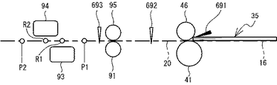
本発明の実施形態について、図面を参照して説明する。まず、図1を参照して、画像読取装置1の概略構成について説明する。図1に示すように、画像読取装置1は、筐体10、給紙トレイ16、及び排紙トレイ18を備えている。以下の説明においては、図1の上側、下側、左側、右側、手前側、奥側を、それぞれ、画像読取装置1の上側、下側、前側、後側、右側、左側とする。   Embodiments of the present invention will be described with reference to the drawings. First, a schematic configuration of the image reading apparatus 1 will be described with reference to FIG. As shown in FIG. 1, the image reading apparatus 1 includes a housing 10, a paper feed tray 16, and a paper discharge tray 18. In the following description, the upper side, the lower side, the left side, the right side, the near side, and the far side in FIG. 1 are respectively referred to as the upper side, the lower side, the front side, the rear side, the right side, and the left side of the image reading apparatus 1.

図1に示すように、筐体10は、第一筐体11及び第二筐体12を有する。第一筐体11及び第二筐体12のそれぞれの形状は、略箱形状である。第一筐体11は、筐体10の下部を形成する。第二筐体12は、第一筐体11に対して上側から重なる。第一筐体11と第二筐体12との上下方向における間の位置には、複数のシート35が搬送される搬送経路20が形成されている。搬送経路20は、画像読取装置1がシート35を取り込んで画像を読み取る過程で、シート35が通過する領域に対応する。搬送経路20は、給紙口10A及び排紙口10Bによって筐体10の外側と繋がる。搬送経路20は、第一筐体11の上面と、第二筐体12の下面との間に定義される。   As illustrated in FIG. 1, the housing 10 includes a first housing 11 and a second housing 12. Each shape of the 1st housing | casing 11 and the 2nd housing | casing 12 is substantially box shape. The first housing 11 forms the lower part of the housing 10. The second housing 12 overlaps the first housing 11 from above. A conveyance path 20 for conveying a plurality of sheets 35 is formed at a position between the first casing 11 and the second casing 12 in the vertical direction. The conveyance path 20 corresponds to a region through which the sheet 35 passes in the process in which the image reading apparatus 1 takes in the sheet 35 and reads an image. The conveyance path 20 is connected to the outside of the housing 10 by a paper feed port 10A and a paper discharge port 10B. The conveyance path 20 is defined between the upper surface of the first housing 11 and the lower surface of the second housing 12.

給紙トレイ16は、第一筐体11のうち給紙口10Aの後ろ側から、後方斜め上側に向けて延びる。給紙トレイ16は、略板形状である。給紙トレイ16の上側の面に、A4サイズ、レターサイズ等の薄紙又は厚紙からなる複数のシート35が載せられる。   The sheet feed tray 16 extends from the rear side of the sheet feed opening 10 </ b> A in the first housing 11 toward the rear obliquely upper side. The paper feed tray 16 has a substantially plate shape. A plurality of sheets 35 made of thin paper or thick paper such as A4 size and letter size are placed on the upper surface of the paper feed tray 16.

排紙トレイ18は、第一筐体11のうち排紙口10Bの下側から、前側に向けて延びる。排紙トレイ18は、略板形状である。排紙トレイ18の上側の面は、排紙口10Bから筐体10の外部に排出されるシート35を受ける。   The discharge tray 18 extends from the lower side of the first casing 11 toward the front side from the lower side of the discharge port 10B. The paper discharge tray 18 has a substantially plate shape. The upper surface of the paper discharge tray 18 receives the sheet 35 discharged from the paper discharge outlet 10 </ b> B to the outside of the housing 10.

図1に示すように、第一筐体11には、給紙ローラ41、搬送ローラ91、及び搬送ローラ92が設けられる。給紙ローラ41、搬送ローラ91、及び搬送ローラ92は、搬送経路20に沿って後方斜め上側から前方斜め下側に順番に並ぶ。   As shown in FIG. 1, the first housing 11 is provided with a paper feed roller 41, a transport roller 91, and a transport roller 92. The paper feed roller 41, the conveyance roller 91, and the conveyance roller 92 are arranged in order along the conveyance path 20 from the rear oblique upper side to the front oblique lower side.

給紙ローラ41は円柱状である。給紙ローラ41の回転軸は、左右方向に沿う。給紙ローラ41の回転軸線に沿って、軸部材42が延びる。軸部材42は、第一筐体11に回転可能に支持される。軸部材42は、後述する第一モータ71(図2参照)の回転に応じて回転する。給紙ローラ41は、軸部材42の回転に応じて、右側面視における反時計回りに回転する(矢印321)。給紙ローラ41の一部(例えば、給紙ローラ41の上に位置する外周部分)は、搬送経路20に向けて突出する。給紙ローラ41と軸部材42との間には、図示しないワンウェイクラッチが設けられている。このワンウェイクラッチは、給紙ローラ41が軸部材42に対して右側面視における反時計回りに空転することを許容する。   The paper feed roller 41 is cylindrical. The rotation axis of the paper feed roller 41 is along the left-right direction. A shaft member 42 extends along the rotation axis of the paper feed roller 41. The shaft member 42 is rotatably supported by the first housing 11. The shaft member 42 rotates according to the rotation of a first motor 71 (see FIG. 2) described later. The paper feed roller 41 rotates counterclockwise in the right side view according to the rotation of the shaft member 42 (arrow 321). A part of the paper feed roller 41 (for example, an outer peripheral portion located on the paper feed roller 41) protrudes toward the conveyance path 20. A one-way clutch (not shown) is provided between the paper feed roller 41 and the shaft member 42. The one-way clutch allows the sheet feeding roller 41 to idle in the counterclockwise direction in the right side view with respect to the shaft member 42.

搬送ローラ91、92は円柱状である。搬送ローラ91、92の回転軸は、左右方向に沿う。搬送ローラ91、92は同一形状を有する。搬送ローラ91の回転軸線に沿って軸部材91Aが延びる。搬送ローラ92の回転軸線に沿って軸部材92Aが延びる。軸部材91A、92Aは、第一筐体11に回転可能に支持される。軸部材91A、92Aは、後述する第二モータ72(図2参照)の回転に応じて回転する。搬送ローラ91は、軸部材91Aの回転に応じて、反時計回りに回転する(矢印323)。搬送ローラ92は、軸部材92Aの回転に応じて、反時計回りに回転する(矢印324)。搬送ローラ91、92の一部(例えば、搬送ローラ91、92の上に位置する外周部分)は、搬送経路20に向けて突出する。   The conveyance rollers 91 and 92 are cylindrical. The rotation axes of the transport rollers 91 and 92 are along the left-right direction. The transport rollers 91 and 92 have the same shape. A shaft member 91 </ b> A extends along the rotation axis of the transport roller 91. A shaft member 92 </ b> A extends along the rotation axis of the transport roller 92. The shaft members 91 </ b> A and 92 </ b> A are rotatably supported by the first housing 11. The shaft members 91A and 92A rotate according to the rotation of a second motor 72 (see FIG. 2) described later. The conveyance roller 91 rotates counterclockwise in accordance with the rotation of the shaft member 91A (arrow 323). The conveyance roller 92 rotates counterclockwise in accordance with the rotation of the shaft member 92A (arrow 324). Part of the transport rollers 91 and 92 (for example, an outer peripheral portion located on the transport rollers 91 and 92) protrudes toward the transport path 20.

以下、搬送経路20に沿った方向を「搬送方向」という。搬送方向は、概して、前方斜め下側と後方斜め上側との間に亘って延びる方向に対応する。ただし、搬送方向は、搬送経路20に沿った方向であるため、第一筐体11の上面と第二筐体12の下面との形状に対応し、直線方向として定義されなくてもよい。即ち、搬送方向は、搬送経路20における位置に応じて、前後、上下、左右方向に対する向きの関係が変化してもよい。搬送方向のうち、搬送経路20における給紙口10A側を「上流」という。搬送方向のうち、搬送経路20における排紙口10B側を「下流」という。   Hereinafter, the direction along the transport path 20 is referred to as “transport direction”. The conveyance direction generally corresponds to a direction extending between the front diagonally lower side and the rear diagonally upper side. However, since the conveyance direction is a direction along the conveyance path 20, it corresponds to the shape of the upper surface of the first housing 11 and the lower surface of the second housing 12 and may not be defined as a linear direction. In other words, the direction of the transport direction may change depending on the position in the transport path 20 in the front-rear, up-down, left-right direction. Among the transport directions, the paper feed port 10A side in the transport path 20 is referred to as “upstream”. Among the transport directions, the discharge port 10B side in the transport path 20 is referred to as “downstream”.

第一筐体11は、第一読取部93を備える。第二筐体12は、第二読取部94を備える。第一読取部93及び第二読取部94は、周知の接触型イメージセンサモジュールである。第一読取部93及び第二読取部94は、後述する制御部50(図2参照)と電気的に接続する。第一読取部93は、搬送経路20の下側において、搬送方向において搬送ローラ91,92の間に設けられる。第二読取部94は、搬送経路20の上側において、搬送方向において搬送ローラ91,92の間に設けられる。第一読取部93及び第二読取部94は、左右方向を主走査方向としている。第一読取部93は、左右方向に直線状に延びるCIS(Contact Image Sensor)21A(図2参照)を備えている。第二読取部94は、左右方向に直線状に延びるCIS21B(図2参照)を備えている。即ち、CIS21A,21Bの主走査方向は、左右方向に沿う。第一読取部93は、搬送経路20に沿って上流から下流に搬送されて、第一読取位置R1(図5参照)に到達したシート35の下面の画像を読み取る。第一読取位置R1は、第一読取部93においてCIS21Aによってシート35の画像が読み取られる位置(言い換えると、CIS21Aの受光素子に結像する物面の位置)に対応する搬送経路20における位置である。第二読取部94は、搬送経路20に沿って上流から下流に向けて搬送されて、第二読取位置R2(図5参照)に到達したシート35の上面の画像を読み取る。第二読取位置R2は、第二読取部94においてCIS21Bによってシート35の画像が読み取られる位置(言い換えると、CIS21Bの受光素子に結像する物面の位置)に対応する搬送経路20における位置である。第一読取部93及び第二読取部94は、読み取った画像のデータを、制御部50に出力する。   The first housing 11 includes a first reading unit 93. The second housing 12 includes a second reading unit 94. The first reading unit 93 and the second reading unit 94 are well-known contact image sensor modules. The 1st reading part 93 and the 2nd reading part 94 are electrically connected with the control part 50 (refer FIG. 2) mentioned later. The first reading unit 93 is provided below the transport path 20 and between the transport rollers 91 and 92 in the transport direction. The second reading unit 94 is provided between the transport rollers 91 and 92 in the transport direction on the upper side of the transport path 20. The first reading unit 93 and the second reading unit 94 have the left-right direction as the main scanning direction. The first reading unit 93 includes a CIS (Contact Image Sensor) 21A (see FIG. 2) extending linearly in the left-right direction. The second reading unit 94 includes a CIS 21B (see FIG. 2) extending linearly in the left-right direction. That is, the main scanning direction of the CIS 21A, 21B is along the left-right direction. The first reading unit 93 reads an image on the lower surface of the sheet 35 that has been conveyed from upstream to downstream along the conveyance path 20 and has reached the first reading position R1 (see FIG. 5). The first reading position R1 is a position in the transport path 20 corresponding to the position at which the image of the sheet 35 is read by the CIS 21A in the first reading unit 93 (in other words, the position of the object surface imaged on the light receiving element of the CIS 21A). . The second reading unit 94 reads an image on the upper surface of the sheet 35 that has been conveyed from upstream to downstream along the conveyance path 20 and has reached the second reading position R2 (see FIG. 5). The second reading position R2 is a position in the transport path 20 corresponding to a position at which the image of the sheet 35 is read by the CIS 21B in the second reading unit 94 (in other words, the position of the object surface imaged on the light receiving element of the CIS 21B). . The first reading unit 93 and the second reading unit 94 output the read image data to the control unit 50.

第二筐体12は、リバースローラ46、従動ローラ95,96、フロントセンサ691、リアAセンサ692、及びリアBセンサ693を備える。給紙ローラ41に対して上側に、リバースローラ46が配置される。リバースローラ46は円柱状である。リバースローラ46の直径は、給紙ローラ41の直径よりも小さい。リバースローラ46の回転軸は左右方向に沿う。リバースローラ46の回転軸線に沿って軸部材47が延びる。軸部材47は、第二筐体12に回転可能に支持されている。リバースローラ46の一部(例えば、リバースローラ46の下に位置する外周部分)は、搬送経路20に向けて突出する。リバースローラ46のうち給紙ローラ41と近接する端部は、搬送経路20において給紙ローラ41に接触する。リバースローラ46は、搬送経路20に対して上側に配置される。軸部材47は、後述する第二モータ72(図2参照)の回転に応じて回転する。軸部材47に伝達された第二モータ72の回転駆動力は、トルクリミッタ482を介して、リバースローラ46に伝達される。リバースローラ46は、トルクリミッタ482を介して軸部材47に接続されている。   The second housing 12 includes a reverse roller 46, driven rollers 95 and 96, a front sensor 691, a rear A sensor 692, and a rear B sensor 693. A reverse roller 46 is disposed above the paper feed roller 41. The reverse roller 46 is cylindrical. The diameter of the reverse roller 46 is smaller than the diameter of the paper feed roller 41. The rotation axis of the reverse roller 46 is along the left-right direction. A shaft member 47 extends along the rotation axis of the reverse roller 46. The shaft member 47 is rotatably supported by the second housing 12. A part of the reverse roller 46 (for example, an outer peripheral portion located below the reverse roller 46) protrudes toward the conveyance path 20. An end portion of the reverse roller 46 that is close to the paper feed roller 41 contacts the paper feed roller 41 in the transport path 20. The reverse roller 46 is disposed on the upper side with respect to the conveyance path 20. The shaft member 47 rotates according to the rotation of a second motor 72 (see FIG. 2) which will be described later. The rotational driving force of the second motor 72 transmitted to the shaft member 47 is transmitted to the reverse roller 46 via the torque limiter 482. The reverse roller 46 is connected to the shaft member 47 via a torque limiter 482.

給紙ローラ41は、リバースローラ46と接触した状態で反時計回りに回転する(矢印321)。この回転に応じて、リバースローラ46に対してトルクが作用する。トルクリミッタ482は、軸部材47とリバースローラ46との間に介在して、リバースローラ46に対して所定の閾値未満のトルクが作用している状態で、軸部材47とリバースローラ46とを接続する。このため、リバースローラ46に対して所定の閾値未満のトルクが作用している場合、リバースローラ46は、軸部材47から受ける回転駆動力に応じて反時計回りに回転する(矢印322)。一方、トルクリミッタ482は、リバースローラ46に対して所定の閾値以上のトルクが作用している状態で、軸部材47とリバースローラ46との接続を解除する。このため、リバースローラ46に対して所定の閾値以上のトルクが作用している場合、リバースローラ46と軸部材47との接続が解除され、リバースローラ46に対して第二モータ72の回転駆動力が伝達されなくなる。   The paper feed roller 41 rotates counterclockwise while being in contact with the reverse roller 46 (arrow 321). In response to this rotation, torque acts on the reverse roller 46. The torque limiter 482 is interposed between the shaft member 47 and the reverse roller 46 and connects the shaft member 47 and the reverse roller 46 in a state where a torque less than a predetermined threshold is acting on the reverse roller 46. To do. Therefore, when a torque less than a predetermined threshold is applied to the reverse roller 46, the reverse roller 46 rotates counterclockwise according to the rotational driving force received from the shaft member 47 (arrow 322). On the other hand, the torque limiter 482 releases the connection between the shaft member 47 and the reverse roller 46 in a state where a torque greater than a predetermined threshold is applied to the reverse roller 46. For this reason, when a torque greater than a predetermined threshold is applied to the reverse roller 46, the connection between the reverse roller 46 and the shaft member 47 is released, and the rotational driving force of the second motor 72 against the reverse roller 46. Will not be transmitted.

所定の閾値は、シート35とリバースローラ46との摩擦、及び、給紙ローラ41とリバースローラ46との摩擦によって、軸部材47とリバースローラ46との接続が解除される値に設定されている。一方、所定の閾値は、給紙ローラ41とリバースローラ46との間におけるシート35同士の摩擦では、軸部材47とリバースローラ46との接続が解除されない値に設定されている。このため、給紙ローラ41とリバースローラ46との間にシート35が二枚以上存在する場合、リバースローラ46は、軸部材47から受ける回転駆動力に応じて、反時計回りに回転する。一方、給紙ローラ41とリバースローラ46との間にシート35が存在しない場合、又は、一枚だけ存在する場合、リバースローラ46は軸部材47から回転駆動力を受けない。   The predetermined threshold value is set to a value at which the connection between the shaft member 47 and the reverse roller 46 is released due to the friction between the sheet 35 and the reverse roller 46 and the friction between the paper feed roller 41 and the reverse roller 46. . On the other hand, the predetermined threshold is set to a value that does not release the connection between the shaft member 47 and the reverse roller 46 due to the friction between the sheets 35 between the paper feed roller 41 and the reverse roller 46. For this reason, when there are two or more sheets 35 between the paper feed roller 41 and the reverse roller 46, the reverse roller 46 rotates counterclockwise according to the rotational driving force received from the shaft member 47. On the other hand, when there is no sheet 35 between the paper feed roller 41 and the reverse roller 46 or when only one sheet exists, the reverse roller 46 does not receive a rotational driving force from the shaft member 47.

従動ローラ95,96は円柱状である。従動ローラ95は、搬送ローラ91の上側に接触する。従動ローラ96は、搬送ローラ92の上側に接触する。従動ローラ95,96の回転軸は、左右方向に沿う。従動ローラ95,96は同一形状を有する。従動ローラ95,96が固定されるそれぞれの軸部材は、第二筐体12に回転可能に支持される。軸部材91A,92Aは、後述する第二モータ72(図2参照)の回転に応じて回転する。従動ローラ95は、図示しないバネによって、搬送ローラ91に向けて付勢される。従動ローラ96は、図示しないバネによって、搬送ローラ92に向けて付勢される。従動ローラ95,96の一部(例えば、従動ローラ95,96の下に位置する外周部分)は、搬送経路20に向けて突出する。   The driven rollers 95 and 96 are cylindrical. The driven roller 95 is in contact with the upper side of the conveying roller 91. The driven roller 96 contacts the upper side of the conveying roller 92. The rotation shafts of the driven rollers 95 and 96 are along the left-right direction. The driven rollers 95 and 96 have the same shape. Each shaft member to which the driven rollers 95 and 96 are fixed is rotatably supported by the second housing 12. The shaft members 91A and 92A rotate according to the rotation of a second motor 72 (see FIG. 2) described later. The driven roller 95 is urged toward the transport roller 91 by a spring (not shown). The driven roller 96 is urged toward the transport roller 92 by a spring (not shown). A part of the driven rollers 95 and 96 (for example, an outer peripheral portion located below the driven rollers 95 and 96) protrudes toward the conveyance path 20.

フロントセンサ691、リアAセンサ692、及びリアBセンサ693は、シート35を検知可能なセンサである。フロントセンサ691、リアAセンサ692、及びリアBセンサ693は、シート35の接触に応じて回動する回動部材と、回動部材の回動を検知可能な周知の光学センサとを含む。フロントセンサ691、リアAセンサ692、及びリアBセンサ693は、後述する制御部50(図2参照)と電気的に接続する。フロントセンサ691、リアAセンサ692、及びリアBセンサ693は、図示しない発光部及び受光部を備え、発光部から発光された光が受光部によって受光されたか否かを検出し、検出結果を示す信号を制御部50に出力する。例えば、シート35が回動部材に接触していない場合、回動部材は発光部から発光された光を遮り、受光部は光を検出しない。一方、シート35が回動部材に接触している場合、回動部材が回動することにより、発光部から発光された光は遮られず、受光部が光を検出する。ただし、発光部と受光部とを、搬送経路20を挟んで対向させることにより、シート35が光を遮ったか否かを検出してもよい。この場合、回動部材は不要になる。   The front sensor 691, the rear A sensor 692, and the rear B sensor 693 are sensors that can detect the seat 35. The front sensor 691, the rear A sensor 692, and the rear B sensor 693 include a rotating member that rotates in response to the contact of the seat 35 and a known optical sensor that can detect the rotation of the rotating member. The front sensor 691, the rear A sensor 692, and the rear B sensor 693 are electrically connected to a control unit 50 (see FIG. 2) described later. The front sensor 691, the rear A sensor 692, and the rear B sensor 693 include a light emitting unit and a light receiving unit (not shown), detect whether or not the light emitted from the light emitting unit is received by the light receiving unit, and indicate the detection result. The signal is output to the control unit 50. For example, when the sheet 35 is not in contact with the rotating member, the rotating member blocks light emitted from the light emitting unit, and the light receiving unit does not detect light. On the other hand, when the sheet 35 is in contact with the rotating member, the light emitted from the light emitting unit is not blocked by the rotation of the rotating member, and the light receiving unit detects the light. However, it may be detected whether or not the sheet 35 blocks light by causing the light emitting unit and the light receiving unit to face each other with the conveyance path 20 interposed therebetween. In this case, the rotating member becomes unnecessary.

フロントセンサ691は、搬送経路20の上側において、搬送方向において給紙口10Aと給紙ローラ41との間の部分に設けられる。言い換えると、フロントセンサ691は、搬送経路20において給紙ローラ41の上流、且つ、給紙トレイ16の前下端部側の給紙口10A付近に配置されている。フロントセンサ691は、フロントセンサ691の配置される位置において、給紙トレイ16に配置されているシート35の有無を検出する。   The front sensor 691 is provided on the upper side of the transport path 20 at a portion between the paper feed port 10A and the paper feed roller 41 in the transport direction. In other words, the front sensor 691 is disposed upstream of the sheet feed roller 41 in the transport path 20 and in the vicinity of the sheet feed opening 10 </ b> A on the front lower end side of the sheet feed tray 16. The front sensor 691 detects the presence / absence of the sheet 35 disposed on the sheet feed tray 16 at the position where the front sensor 691 is disposed.

リアAセンサ692は、搬送経路20の上側において、搬送方向において給紙ローラ41と搬送ローラ91の間との部分に設けられる。言い換えると、リアAセンサ692は、搬送経路20の途中において、給紙ローラ41の下流に配置されている。リアAセンサ692は、リアAセンサ692の配置される位置において、搬送経路20に沿って給紙ローラ41から搬送ローラ91へ向けて搬送されるシート35の有無を検出する。   The rear A sensor 692 is provided on the upper side of the transport path 20 at a portion between the paper feed roller 41 and the transport roller 91 in the transport direction. In other words, the rear A sensor 692 is disposed downstream of the paper feed roller 41 in the middle of the transport path 20. The rear A sensor 692 detects the presence or absence of the sheet 35 conveyed from the paper feed roller 41 toward the conveyance roller 91 along the conveyance path 20 at the position where the rear A sensor 692 is disposed.

リアBセンサ693は、搬送経路20の上側において、搬送方向において搬送ローラ91と第一読取部93及び第二読取部94の間の部分に設けられる。言い換えると、リアBセンサ693は、搬送経路20の途中において、搬送ローラ91の下流であり、且つ第一読取位置R1及び第二読取位置R2(図5参照)の上流に配置されている。リアBセンサ693は、リアBセンサ693の配置される位置において、搬送経路20に沿って搬送ローラ91から第一読取部93及び第二読取部94へ向けて搬送されるシート35の有無を検出する。   The rear B sensor 693 is provided on the upper side of the conveyance path 20 in a portion between the conveyance roller 91 and the first reading unit 93 and the second reading unit 94 in the conveyance direction. In other words, the rear B sensor 693 is arranged in the middle of the conveyance path 20 downstream of the conveyance roller 91 and upstream of the first reading position R1 and the second reading position R2 (see FIG. 5). The rear B sensor 693 detects the presence or absence of the sheet 35 conveyed from the conveyance roller 91 toward the first reading unit 93 and the second reading unit 94 along the conveyance path 20 at the position where the rear B sensor 693 is disposed. To do.

図2を参照し、画像読取装置1の電気的構成について説明する。図2に示すように、画像読取装置1は、入出力インターフェースインターフェース(以下、「入出力I/F」という。)30、外部通信I/F40、及び制御部50とを備える。   The electrical configuration of the image reading apparatus 1 will be described with reference to FIG. As shown in FIG. 2, the image reading apparatus 1 includes an input / output interface interface (hereinafter referred to as “input / output I / F”) 30, an external communication I / F 40, and a control unit 50.

入出力I/F30は、所定の規格(例えば、Universal Serial Bus (USB))に適合したインターフェース素子であり、画像読取装置1とUSBメモリ等のリムーバルメディアを接続するためのインターフェースである。本実施形態において、入出力I/F30は、USBポートである。   The input / output I / F 30 is an interface element conforming to a predetermined standard (for example, Universal Serial Bus (USB)), and is an interface for connecting the image reading apparatus 1 and a removable medium such as a USB memory. In the present embodiment, the input / output I / F 30 is a USB port.

外部通信I/F40は、画像読取装置1をLANに接続されているPC(パーソナルコンピュータ)等の外部装置との間で、LANを経由した通信を行うための回路等を備えている。なお、外部通信I/F40は、LANを経由せずに外部装置との間で直接通信を行うためのインターフェース(例えばUSBインターフェース)で構成されてもよい。   The external communication I / F 40 includes a circuit for performing communication via the LAN between the image reading apparatus 1 and an external device such as a PC (personal computer) connected to the LAN. Note that the external communication I / F 40 may be configured with an interface (for example, a USB interface) for performing direct communication with an external device without going through a LAN.

制御部50は、画像読取装置1全体の制御を司るCPU51を備える。また、制御部50は、CPU51からの指示に応じて、第一モータ71、第二モータ72に対して駆動信号(例えば、駆動電流)を送信する所定の電気回路等を備える。CPU51は、RAM52、ROM53と電気的に接続する。RAM52は、CPU51による演算処理で得られた演算結果等、各種のデータを一時的に記憶する。特に、RAM52は、シート35の画像の画像データを記憶する画像データ記憶エリア521の記憶領域を少なくとも確保している。   The control unit 50 includes a CPU 51 that controls the entire image reading apparatus 1. The control unit 50 includes a predetermined electric circuit that transmits a drive signal (for example, a drive current) to the first motor 71 and the second motor 72 in response to an instruction from the CPU 51. The CPU 51 is electrically connected to the RAM 52 and the ROM 53. The RAM 52 temporarily stores various data such as calculation results obtained by calculation processing by the CPU 51. In particular, the RAM 52 secures at least a storage area of the image data storage area 521 for storing image data of the image of the sheet 35.

ROM53は、OSを記憶する。また、ROM53は、CPU51に後述のメイン処理(図3及び図4参照)を実行させるプログラム、及び各種プログラムが使用するフラグやデータの初期値等を記憶する。ROM53は、非一時的な記憶媒体の一例である。非一時的な記憶媒体は、情報を記憶する期間に関わらず、情報を記憶可能な記憶媒体であればよい。非一時的な記憶媒体は、一時的な記憶媒体(例えば、伝送される信号)を含まなくてもよい。本実施形態における記憶装置はROM53であるが、記憶装置は、情報を記憶する時間の長さに関わらずデータを保持できる、他の非一時的な記憶媒体、例えば、フラッシュメモリ、RAM等で構成されてもよい。   The ROM 53 stores the OS. The ROM 53 stores a program for causing the CPU 51 to execute a main process (see FIGS. 3 and 4) described later, flags and initial values of data used by various programs, and the like. The ROM 53 is an example of a non-temporary storage medium. The non-temporary storage medium may be any storage medium that can store information regardless of the period in which the information is stored. The non-transitory storage medium may not include a temporary storage medium (for example, a signal to be transmitted). The storage device in the present embodiment is the ROM 53, but the storage device is composed of another non-transitory storage medium such as a flash memory or a RAM that can hold data regardless of the length of time for storing information. May be.

制御部50は、第一モータ71、第二モータ72、第一読取部93、第二読取部94、フロントセンサ691、リアAセンサ692、リアBセンサ693と電気的に接続する。第一モータ71は、軸部材42(図1参照)を介して給紙ローラ41を回転駆動する。第二モータ72は、軸部材47、91A、92Aを介してリバースローラ46、搬送ローラ91,92を回転駆動する。第一モータ71及び第二モータ72には、種々のタイプのモータを使用できる。本実施形態では、第一モータ71及び第二モータ72は、共にステッピングモータである。ステッピングモータの駆動信号は、通常、所定周波数のパルス信号である。制御部50は、CPU51の制御に応じて、第一モータ71及び第二モータ72をステップ駆動するための駆動信号を生成することで、第一モータ71及び第二モータ72を駆動する。第一モータ71及び第二モータ72の回転速度の切替えは、例えば、駆動パルスの周波数を切替えることによって行われる。   The control unit 50 is electrically connected to the first motor 71, the second motor 72, the first reading unit 93, the second reading unit 94, the front sensor 691, the rear A sensor 692, and the rear B sensor 693. The first motor 71 rotationally drives the paper feed roller 41 via the shaft member 42 (see FIG. 1). The second motor 72 rotationally drives the reverse roller 46 and the conveying rollers 91 and 92 via the shaft members 47, 91A and 92A. Various types of motors can be used for the first motor 71 and the second motor 72. In the present embodiment, the first motor 71 and the second motor 72 are both stepping motors. The driving signal for the stepping motor is usually a pulse signal having a predetermined frequency. The control unit 50 drives the first motor 71 and the second motor 72 by generating a drive signal for stepwise driving the first motor 71 and the second motor 72 in accordance with the control of the CPU 51. The rotation speeds of the first motor 71 and the second motor 72 are switched, for example, by switching the frequency of the drive pulse.

第一読取部93は、CIS21A及びAFE(Analog Front End)22Aを備えている。第二読取部94は、CIS22A及びAFE22Bを備えている。CIS21A,21Bは、シート35の画像を読み取る。AFE22A,22Bは、CIS22A,21Bによって読み取られたアナログの画像をデジタルの画像データに変換する。画像データは、RAM52の画像データ記憶エリア521にライン毎に格納される。「ライン毎」とは、第一読取部93及び第二読取部94の主走査方向(「紙幅方向」に相当)に並ぶ画素列毎という意味である。画像データ記憶エリア521に格納された画像データは、CPU51によって読み出され、ガンマ補正や拡大、縮小などの画像処理が施される。画像処理された画像データは、CPU51によって圧縮や符号化等のデータ処理が施された後に再び画像データ記憶エリア521に格納される。そして、画像データ記憶エリア521に格納された、データ処理の施された画像データはPC等外部装置の転送指令に応じて、ライン毎に順次入出力I/F30又は外部通信I/F40を介して外部装置に転送される。   The first reading unit 93 includes a CIS 21A and an AFE (Analog Front End) 22A. The second reading unit 94 includes a CIS 22A and an AFE 22B. The CIS 21A, 21B reads an image on the sheet 35. The AFEs 22A and 22B convert analog images read by the CISs 22A and 21B into digital image data. The image data is stored for each line in the image data storage area 521 of the RAM 52. “For each line” means for each pixel row arranged in the main scanning direction (corresponding to the “paper width direction”) of the first reading unit 93 and the second reading unit 94. The image data stored in the image data storage area 521 is read by the CPU 51 and subjected to image processing such as gamma correction, enlargement and reduction. The image data subjected to the image processing is stored in the image data storage area 521 again after being subjected to data processing such as compression and encoding by the CPU 51. The image data subjected to the data processing stored in the image data storage area 521 is sequentially sent via the input / output I / F 30 or the external communication I / F 40 for each line according to a transfer command from an external device such as a PC. Transferred to external device.

フロントセンサ691は、給紙トレイ16に配置されているシート35を検出した場合、制御部50にON信号を出力し、給紙トレイ16に配置されているシート35を検出しない場合、制御部50にOFF信号を出力する。リアAセンサ692は、リアAセンサ692の配置される位置のシート35を検出した場合、制御部50にON信号を出力し、リアAセンサ692の配置される位置のシート35を検出しない場合、制御部50にOFF信号を出力する。リアBセンサ693は、リアBセンサ693の配置される位置のシート35を検出した場合、制御部50にON信号を出力し、リアBセンサ693の配置される位置のシート35を検出しない場合、制御部50にOFF信号を出力する。   The front sensor 691 outputs an ON signal to the control unit 50 when detecting the sheet 35 arranged in the paper feed tray 16, and controls the control unit 50 when detecting the sheet 35 arranged in the paper feed tray 16. An OFF signal is output. When the rear A sensor 692 detects the seat 35 at the position where the rear A sensor 692 is disposed, the rear A sensor 692 outputs an ON signal to the control unit 50, and when the rear A sensor 692 does not detect the sheet 35 at the position where the rear A sensor 692 is disposed, An OFF signal is output to the control unit 50. When the rear B sensor 693 detects the seat 35 at the position where the rear B sensor 693 is disposed, the rear B sensor 693 outputs an ON signal to the control unit 50, and when the rear B sensor 693 does not detect the sheet 35 at the position where the rear B sensor 693 is disposed, An OFF signal is output to the control unit 50.

図1及び図5を参照し、画像読取装置1によって複数のシート35が搬送され、シート35の画像が読み取られる場合の動作について説明する。使用者によって複数のシート35が給紙トレイ16の上面に配置されると、フロントセンサ691がシート35を検出し、制御部50に検出信号を送信する。これによって、制御部50は、給紙トレイ16にシート35が配置されたことを検出する。   With reference to FIGS. 1 and 5, an operation when a plurality of sheets 35 are conveyed by the image reading apparatus 1 and an image on the sheet 35 is read will be described. When the user places a plurality of sheets 35 on the upper surface of the paper feed tray 16, the front sensor 691 detects the sheet 35 and transmits a detection signal to the control unit 50. As a result, the control unit 50 detects that the sheet 35 has been placed in the paper feed tray 16.

制御部50は、第一モータ71を回転駆動する。第一モータ71の回転駆動力は、軸部材42に伝達されて、給紙ローラ41を反時計回りに回転させる(矢印321)。制御部50は、第二モータ72を回転駆動する。第二モータ72の回転駆動力は、軸部材91A,92Aに伝達されて、搬送ローラ91,92のそれぞれを反時計回りに回転させる(矢印323,324)。なお、複数のシート35が給紙ローラ41とリバースローラ46との接触点に到達するまでは、リバースローラ46に対して作用する給紙ローラ41とリバースローラ46との摩擦によるトルクが所定の閾値以上となる。これに応じて、トルクリミッタ482は、リバースローラ46と軸部材47との間の回転駆動力の伝達を解除する。リバースローラ46は、給紙ローラ41の反時計回りの回転に従動して、時計回りに回転する。複数のシート35が給紙ローラ41とリバースローラ46との接触点に到達すると、シート35同士の間の摩擦によるトルクがリバースローラ46に対して作用する。このトルクは所定の閾値未満であるので、第二モータ72の回転駆動力がリバースローラ46に伝達され、リバースローラ46が反時計回りに回転する(矢印322)。   The control unit 50 drives the first motor 71 to rotate. The rotational driving force of the first motor 71 is transmitted to the shaft member 42 to rotate the paper feed roller 41 counterclockwise (arrow 321). The control unit 50 drives the second motor 72 to rotate. The rotational driving force of the second motor 72 is transmitted to the shaft members 91A and 92A to rotate the transport rollers 91 and 92 counterclockwise (arrows 323 and 324). Until a plurality of sheets 35 reach the contact point between the paper feed roller 41 and the reverse roller 46, the torque due to the friction between the paper feed roller 41 and the reverse roller 46 acting on the reverse roller 46 is a predetermined threshold value. That's it. In response to this, the torque limiter 482 cancels transmission of the rotational driving force between the reverse roller 46 and the shaft member 47. The reverse roller 46 is rotated in the clockwise direction following the counterclockwise rotation of the paper supply roller 41. When the plurality of sheets 35 reach the contact point between the sheet feeding roller 41 and the reverse roller 46, torque due to friction between the sheets 35 acts on the reverse roller 46. Since this torque is less than a predetermined threshold value, the rotational driving force of the second motor 72 is transmitted to the reverse roller 46, and the reverse roller 46 rotates counterclockwise (arrow 322).

上記の状態で、搬送経路20に沿って搬送方向の下流に移動する複数のシート35のうち最も下側のシート351に、給紙ローラ41が下側から接触する。給紙ローラ41が反時計回りに回転することに応じて、複数のシート35は、搬送経路20に沿って下流に移動する。複数のシート35の下流端部は、給紙ローラ41とリバースローラ46との接触点に到達する。このとき、リバースローラ46は、シート351と、シート351よりも上側のシート35を、給紙ローラ41との接触点で挟む。リバースローラ46が反時計回りに回転することによって、シート351と、シート351よりも上側のシート35とが分離される。給紙ローラ41が反時計回りの回転を継続することに応じ、シート351は接触点よりも下流に移動する。シート351よりも上側のシート35は、接触点に対して上流に残る。このような給紙ローラ41及びリバースローラ46の回転によって、複数のシート35からシート351が分離される。複数のシート35から分離された1枚のシート35は、搬送経路20に沿って下流に移動する。リアAセンサ692は、給紙ローラ41とリバースローラ46との接触点から搬送経路20に沿って下流に移動したシート35を検出し、制御部50に検出信号を送信する。これによって、制御部50は、リアAセンサ692の配置される位置にシート35があることを検出する。   In the above state, the sheet feeding roller 41 contacts the lowermost sheet 351 among the plurality of sheets 35 moving downstream in the conveyance direction along the conveyance path 20 from below. The plurality of sheets 35 move downstream along the conveyance path 20 in response to the rotation of the sheet feed roller 41 counterclockwise. The downstream ends of the plurality of sheets 35 reach the contact point between the paper feed roller 41 and the reverse roller 46. At this time, the reverse roller 46 sandwiches the sheet 351 and the sheet 35 above the sheet 351 at the contact point with the paper feed roller 41. As the reverse roller 46 rotates counterclockwise, the sheet 351 and the sheet 35 above the sheet 351 are separated. As the paper feed roller 41 continues to rotate counterclockwise, the sheet 351 moves downstream from the contact point. The sheet 35 above the sheet 351 remains upstream with respect to the contact point. The sheet 351 is separated from the plurality of sheets 35 by such rotation of the sheet feeding roller 41 and the reverse roller 46. One sheet 35 separated from the plurality of sheets 35 moves downstream along the transport path 20. The rear A sensor 692 detects the sheet 35 that has moved downstream along the conveyance path 20 from the contact point between the paper feed roller 41 and the reverse roller 46, and transmits a detection signal to the control unit 50. Accordingly, the control unit 50 detects that the seat 35 is present at the position where the rear A sensor 692 is disposed.

なお、給紙ローラ41及びリバースローラ46の回転によって、複数のシート35から1枚のシート35が確実に分離されるには、給紙ローラ41の周速に対して、リバースローラ46の周速が一定割合以上である必要がある。また、給紙ローラ41の周速が所定の周速を下回ると、給紙ローラ41の回転によるシート35の搬送力が不足して、シート35の空送が生じやすくなる。このため、給紙ローラ41の回転によるシート35の移動が確実に行われるには、給紙ローラ41の周速が所定の周速以上である必要がある。画像読取装置1は、第一モータ71が駆動する場合には、第一モータ71の回転速度を、シート35の空送が生じにくい周速である周速Haで給紙ローラ41を回転させる回転速度とすることで、シート35の空送が発生することを防止している。   In order to reliably separate one sheet 35 from the plurality of sheets 35 by the rotation of the paper feed roller 41 and the reverse roller 46, the peripheral speed of the reverse roller 46 is higher than the peripheral speed of the paper feed roller 41. Must be above a certain percentage. Further, when the peripheral speed of the paper feed roller 41 is lower than a predetermined peripheral speed, the conveyance force of the sheet 35 due to the rotation of the paper feed roller 41 is insufficient, and the sheet 35 is likely to be skipped. For this reason, in order to reliably move the sheet 35 by the rotation of the paper feed roller 41, the peripheral speed of the paper feed roller 41 needs to be equal to or higher than a predetermined peripheral speed. In the image reading apparatus 1, when the first motor 71 is driven, the rotation speed of the first motor 71 is rotated so that the sheet feeding roller 41 is rotated at a circumferential speed Ha that is a circumferential speed at which the sheet 35 is less likely to be idle. By setting the speed, it is possible to prevent the sheet 35 from being idle.

リアAセンサ692の下流に搬送されたシート35は、搬送経路20に沿って下流に移動する。搬送ローラ91は、搬送経路20に沿って移動するシート35に下側から接触し、従動ローラ95との間にシート35を挟んで、シート35を下流に更に搬送する。リアBセンサ693はシート35を検出し、制御部50に検出信号を送信する。これによって、制御部50は、リアBセンサ693の配置される位置にシート35があることを検出する。   The sheet 35 conveyed downstream of the rear A sensor 692 moves downstream along the conveyance path 20. The conveyance roller 91 comes into contact with the sheet 35 moving along the conveyance path 20 from the lower side, sandwiches the sheet 35 with the driven roller 95, and further conveys the sheet 35 downstream. The rear B sensor 693 detects the seat 35 and transmits a detection signal to the control unit 50. Thus, the control unit 50 detects that the seat 35 is at the position where the rear B sensor 693 is disposed.

リアBセンサ693の下流に搬送されたシート35は、搬送経路20に沿って下流に移動する。搬送ローラ91は、搬送経路20に沿って移動するシート35に下側から接触し、シート35を下流に更に搬送する。搬送ローラ91の下流に配置された第一読取部93は、シート35の下面の画像を読み取る。搬送ローラ91の下流に配置された第二読取部94は、シート35の上面の画像を読み取る。第一読取部93及び第二読取部94の出力信号は、制御部50に伝達され、データ化される。   The sheet 35 conveyed downstream of the rear B sensor 693 moves downstream along the conveyance path 20. The conveyance roller 91 comes into contact with the sheet 35 moving along the conveyance path 20 from below, and further conveys the sheet 35 downstream. A first reading unit 93 disposed downstream of the conveyance roller 91 reads an image on the lower surface of the sheet 35. The second reading unit 94 disposed downstream of the conveyance roller 91 reads an image on the upper surface of the sheet 35. Output signals of the first reading unit 93 and the second reading unit 94 are transmitted to the control unit 50 and converted into data.

画像読取装置1において、シート35の搬送方向(即ち、副走査方向)における搬送速度は、主走査方向における読取解像度に合わせて設定される。第一読取部93及び第二読取部94による画像の読み取り周期が一定である場合、第一読取部93及び第二読取部94がシート35の画像を単位時間毎にライン毎に読み取った回数である読取ライン数は、搬送速度に比例する。画像読取装置1は、画像読取時の搬送ローラ91,92による複数のシート35の搬送速度を速くする程、画像データの読取ライン数を減少させることができるので、画像データの副走査方向の読取解像度を低くすることができる。また、画像読取装置1は、画像読取時の搬送ローラ91,92による複数のシート35の搬送速度を遅くする程、画像データの読取ライン数を増加させることができるので、画像データの副走査方向の読取解像度を高くすることができる。第一読取部93及び第二読取部94によってシート35の画像が読み取られる時の搬送ローラ91,92による複数のシート35の搬送速度は、画像読取結果に必要な読取解像度と、第一読取部93及び第二読取部94による画像データの処理速度等の仕様に応じて調整される。   In the image reading apparatus 1, the conveyance speed of the sheet 35 in the conveyance direction (that is, the sub-scanning direction) is set according to the reading resolution in the main scanning direction. When the reading period of the images by the first reading unit 93 and the second reading unit 94 is constant, the number of times the first reading unit 93 and the second reading unit 94 read the image of the sheet 35 for each line per unit time. A certain number of reading lines is proportional to the conveyance speed. The image reading apparatus 1 can reduce the number of read lines of image data as the conveying speed of the plurality of sheets 35 by the conveying rollers 91 and 92 at the time of image reading is increased. The resolution can be lowered. Further, the image reading apparatus 1 can increase the number of read lines of image data as the conveying speed of the plurality of sheets 35 by the conveying rollers 91 and 92 at the time of image reading is reduced. Reading resolution can be increased. The conveyance speed of the plurality of sheets 35 by the conveyance rollers 91 and 92 when the image of the sheet 35 is read by the first reading unit 93 and the second reading unit 94 depends on the reading resolution necessary for the image reading result and the first reading unit. 93 and the second reading unit 94 are adjusted according to specifications such as the processing speed of image data.

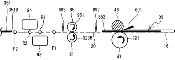
画像読取時における第一読取部93及び第二読取部94に対する複数のシート35の搬送速度は、搬送ローラ91,92の周速によって規定される。本実施形態において、制御部50は、シート35の画像読取時の搬送ローラ91,92が周速Lbで回転するように第二モータ72を制御する。画像読取時とは、画像読取開始から画像読取終了までの間である。画像読取開始とは、制御部50によって、第一読取部93のCIS21A及び第二読取部94のCIS21Bに画像の読取開始指示が送信され、RAM52の画像データ記憶エリア521にライン毎の画像データの記憶が開始されることである。制御部50による画像読取開始に係る処理は、給紙ローラ41によって搬送経路20を搬送されるシート35の先端が、リアBセンサ693の配置される位置を通過することに伴い、リアBセンサ693が「OFF」から「ON」になることを契機に行われる。これにより、第一読取部93の第一読取位置R1及び第二読取部94の第二読取位置R2に到達したシート35の画像が読み取られる。   The conveyance speed of the plurality of sheets 35 with respect to the first reading unit 93 and the second reading unit 94 at the time of image reading is defined by the peripheral speeds of the conveyance rollers 91 and 92. In the present embodiment, the control unit 50 controls the second motor 72 so that the conveyance rollers 91 and 92 at the time of image reading of the sheet 35 rotate at the peripheral speed Lb. The time of image reading is from the start of image reading to the end of image reading. The image reading start means that the control unit 50 sends an image reading start instruction to the CIS 21A of the first reading unit 93 and the CIS 21B of the second reading unit 94, and stores the image data for each line in the image data storage area 521 of the RAM 52. The memory is to be started. The processing related to the start of image reading by the control unit 50 is performed as the leading edge of the sheet 35 conveyed on the conveyance path 20 by the paper feed roller 41 passes the position where the rear B sensor 693 is disposed. Is performed when “OFF” is changed to “ON”. Accordingly, the image of the sheet 35 that has reached the first reading position R1 of the first reading unit 93 and the second reading position R2 of the second reading unit 94 is read.

また、画像読取終了とは、制御部50によって、第一読取部93のCIS21A及び第二読取部94のCIS21Bに画像の読取終了指示が送信され、RAM52の画像データ記憶エリア521への画像データの記憶が終了されることである。制御部50による画像読取終了に係る処理は、搬送ローラ92によって搬送経路20を搬送されるシート35の後端が、読取終了位置P2(図5参照)を通過することを契機に行われる。これにより、第一読取部93及び第二読取部94によるシート35の画像の読み取りが終了する。   The image reading end means that the control unit 50 sends an image reading end instruction to the CIS 21A of the first reading unit 93 and the CIS 21B of the second reading unit 94, and the image data is stored in the image data storage area 521 of the RAM 52. The memory is to be terminated. The processing related to the end of image reading by the control unit 50 is performed when the trailing end of the sheet 35 conveyed on the conveying path 20 by the conveying roller 92 passes the reading end position P2 (see FIG. 5). Thereby, the reading of the image of the sheet 35 by the first reading unit 93 and the second reading unit 94 is completed.

なお、図5に示すように、第一読取位置R1は、第二読取位置R2よりも搬送経路20における上流に配置されている。読取終了位置P2は、後述する第一位置P1よりも、搬送方向の下流の位置である。読取終了位置P2は、例えば、第二読取位置R2よりも搬送経路20における下流の所定位置に配置されている。画像読取装置1において、シート35が搬送方向に対して斜めに傾いて搬送されて第一読取位置R1及び第二読取位置R2を通過した場合等に、シート35の画像が斜めに読み取られることがある。このような場合に得られた画像データを補正すること等を目的として、最終的な読取結果よりも広い範囲で画像を読み取るオーバースキャンが行われることがある。読取終了位置P2は、オーバースキャンに必要なシート35の搬送量等を勘案して、第一読取位置R1及び第二読取位置R2よりも下流に設定されている。ただし、例えば、読取終了位置P2が使用者の設定によって変更される場合、読取終了位置P2は、後述する第一位置P1よりも下流であれば、第一読取位置R1又は第二読取位置R2よりも上流に配置されていてもよい。   As shown in FIG. 5, the first reading position R1 is disposed upstream of the second reading position R2 in the transport path 20. The reading end position P2 is a position downstream of the first position P1 described later in the transport direction. For example, the reading end position P2 is arranged at a predetermined position downstream of the second reading position R2 in the transport path 20. In the image reading apparatus 1, when the sheet 35 is conveyed obliquely with respect to the conveying direction and passes through the first reading position R1 and the second reading position R2, the image on the sheet 35 may be read obliquely. is there. In order to correct the image data obtained in such a case, overscan that reads an image in a wider range than the final reading result may be performed. The reading end position P2 is set downstream of the first reading position R1 and the second reading position R2 in consideration of the conveyance amount of the sheet 35 necessary for the overscan. However, for example, when the reading end position P2 is changed by the user's setting, if the reading end position P2 is downstream of the first position P1 described later, the first reading position R1 or the second reading position R2 is used. May also be arranged upstream.

本実施形態において、制御部50は、画像読取時以外における搬送ローラ91,92の周速Hbが、画像読取時における搬送ローラ91,92の周速Lbよりも速くなるように第二モータ72を制御する。画像読取時以外においては、複数のシート35の搬送速度を読取解像度に応じて設定する必要がない。画像読取装置1は、画像読取時以外には搬送ローラ91,92の周速を周速Hbにして搬送経路20におけるシート35の搬送速度を上昇することで、搬送経路20におけるシート35同士の間隔を詰め、複数のシート35全体の画像読取に必要な時間を短縮している。   In the present embodiment, the controller 50 controls the second motor 72 so that the peripheral speed Hb of the transport rollers 91 and 92 other than during image reading is faster than the peripheral speed Lb of the transport rollers 91 and 92 during image reading. Control. Except at the time of image reading, it is not necessary to set the conveyance speed of the plurality of sheets 35 according to the reading resolution. The image reading apparatus 1 increases the conveying speed of the sheet 35 in the conveying path 20 by setting the peripheral speed of the conveying rollers 91 and 92 to the peripheral speed Hb at times other than the time of image reading, so that the interval between the sheets 35 in the conveying path 20 The time required for image reading of the entire plurality of sheets 35 is shortened.

また、シート35の先端がリアBセンサ693の配置される位置を通過することに伴い、リアBセンサ693が「OFF」から「ON」になることを契機に、制御部50は第一モータ71を停止させる。これにより、給紙ローラ41は停止する。その後に、画像読取が開始される。画像読取時には、シート35が、搬送ローラ91,92によって搬送方向の下流に向けて順次搬送される。シート35の後端が第一位置P1まで搬送されたことに応じて、制御部50は、給紙ローラ41が周速Haで回転するように第二モータ72を制御することで、次に読み取るシート35を搬送ローラ91へ向けて搬送する。第一位置P1は、搬送経路20におけるリアBセンサ693と第一読取位置R1との間の位置である。なお、本実施形態では、給紙ローラ41が回転する場合、画像読取時及び画像読取時以外のいずれにおいても、給紙ローラ41の周速はHaである。これにより、給紙ローラ41の回転不足によるシート35の空送の発生が低減される。本実施形態において、給紙ローラ41の周速Ha、搬送ローラ91,92の周速Hb,Lbは、下記の関係となっている。
Lb<Ha≦Hb
Further, when the leading edge of the seat 35 passes through the position where the rear B sensor 693 is disposed, the control unit 50 triggers the first motor 71 when the rear B sensor 693 is changed from “OFF” to “ON”. Stop. As a result, the paper feed roller 41 stops. Thereafter, image reading is started. At the time of image reading, the sheet 35 is sequentially conveyed toward the downstream in the conveyance direction by the conveyance rollers 91 and 92. In response to the trailing edge of the sheet 35 being conveyed to the first position P1, the control unit 50 controls the second motor 72 so that the paper feed roller 41 rotates at the peripheral speed Ha, and then reads. The sheet 35 is conveyed toward the conveyance roller 91. The first position P1 is a position between the rear B sensor 693 and the first reading position R1 in the transport path 20. In the present embodiment, when the paper feed roller 41 rotates, the peripheral speed of the paper feed roller 41 is Ha both when the image is read and when the image is not read. Thereby, the occurrence of idle feeding of the sheet 35 due to insufficient rotation of the paper feed roller 41 is reduced. In the present embodiment, the peripheral speed Ha of the paper feed roller 41 and the peripheral speeds Hb and Lb of the transport rollers 91 and 92 have the following relationship.
Lb <Ha ≦ Hb

搬送ローラ92は、第一読取位置R1及び第二読取位置R2を通過したシート35に下側から接触し、従動ローラ96との間にシート35を挟んで、シート35を下流に更に搬送する。シート35は、排紙口10Bから筐体10の外部に排出され、排紙トレイ18に配置される。   The conveyance roller 92 contacts the sheet 35 that has passed through the first reading position R <b> 1 and the second reading position R <b> 2 from the lower side, sandwiches the sheet 35 between the driven roller 96, and further conveys the sheet 35 downstream. The sheet 35 is discharged from the paper discharge outlet 10 </ b> B to the outside of the housing 10 and is disposed on the paper discharge tray 18.

図3から図12を参照し、本実施形態における画像読取装置1のメイン処理について説明する。なお、図5から図12においては、搬送経路20においてシート35が搬送される様子を簡略化して説明するために、搬送経路20を水平に延ばした状態で示している。また、軸部材42,47,91A及び搬送ローラ92については、図示を省略している。   With reference to FIGS. 3 to 12, the main processing of the image reading apparatus 1 in the present embodiment will be described. In FIGS. 5 to 12, in order to simplify and describe how the sheet 35 is conveyed on the conveyance path 20, the conveyance path 20 is shown in a state of being extended horizontally. The shaft members 42, 47, 91A and the conveyance roller 92 are not shown.

図5に示すように、給紙トレイ16に複数のシート35が配置されず、画像読取装置1の操作部(図示せず)を介してシート35の画像の読取開始指示が入力されていない時点においては、画像読取装置1は待機状態を維持している。待機状態の画像読取装置1では、第一モータ71及び第二モータ72のいずれも駆動されていないので、給紙ローラ41、リバースローラ46、搬送ローラ91,92のいずれも回転していない。また、フロントセンサ691、リアAセンサ692、及びリアBセンサ693のいずれも、制御部50にOFF信号を出力している。   As shown in FIG. 5, when a plurality of sheets 35 are not arranged in the paper feed tray 16 and an instruction to start reading an image of the sheet 35 is not input via the operation unit (not shown) of the image reading apparatus 1. In FIG. 2, the image reading apparatus 1 maintains a standby state. In the image reading apparatus 1 in the standby state, since neither the first motor 71 nor the second motor 72 is driven, none of the paper feed roller 41, the reverse roller 46, and the transport rollers 91 and 92 are rotating. All of the front sensor 691, the rear A sensor 692, and the rear B sensor 693 output an OFF signal to the control unit 50.

図6に示すように、給紙トレイ16に複数のシート35が配置されると、フロントセンサ691は、給紙トレイ16に配置されているシート35を検出し、制御部50にON信号を出力する。なお、図6では、フロントセンサ691を黒色で示すことで、フロントセンサ691が制御部50にON信号を出力していることを模式的に表している。この状態で、使用者が画像読取装置1の操作部を操作してシート35の画像の読取開始指示を入力すると、CPU51は、ROM53に記憶されたプログラムを実行することによってメイン処理を開始する。   As shown in FIG. 6, when a plurality of sheets 35 are arranged in the paper feed tray 16, the front sensor 691 detects the sheets 35 arranged in the paper feed tray 16 and outputs an ON signal to the control unit 50. To do. In FIG. 6, the front sensor 691 is shown in black to schematically indicate that the front sensor 691 outputs an ON signal to the control unit 50. In this state, when the user operates the operation unit of the image reading apparatus 1 and inputs an instruction to start reading the image of the sheet 35, the CPU 51 starts the main process by executing the program stored in the ROM 53.

図3に示すように、メイン処理が開始されると、CPU51は、第一モータ71を駆動する指示を、制御部50を介して第一モータ71に送信する(S11)。第一モータ71の駆動開始時には、徐々に駆動パルスの周波数を増加していくスルーアップ制御が行われる。CPU51から駆動開始指示を受けた第一モータ71は、スルーアップ制御によって徐々に回転速度を増加し、スルーアップに必要な所定のステップ数の駆動後に給紙ローラ41を周速Haで回転させる回転速度に至る。給紙ローラ41は、第一モータ71のスルーアップに応じて徐々にスルーアップし、周速Haにて定速回転する(矢印321、図7参照)。   As shown in FIG. 3, when the main process is started, the CPU 51 transmits an instruction to drive the first motor 71 to the first motor 71 via the control unit 50 (S11). At the start of driving of the first motor 71, through-up control is performed in which the frequency of the drive pulse is gradually increased. The first motor 71 that has received a drive start instruction from the CPU 51 gradually increases the rotational speed by through-up control, and rotates the paper feed roller 41 at the circumferential speed Ha after driving a predetermined number of steps necessary for through-up. To speed. The paper feed roller 41 gradually slews up according to the through-up of the first motor 71, and rotates at a constant speed at the circumferential speed Ha (see arrow 321 and FIG. 7).

CPU51は、搬送ローラ91,92を周速Hbで回転させる回転速度で第二モータ72を駆動する指示を、制御部50を介して第二モータ72に送信する(S12)。CPU51から駆動開始指示を受けた第二モータ72は、スルーアップ制御によって徐々に回転速度を増加し、スルーアップに必要な所定のステップ数の駆動後に搬送ローラ91,92を周速Hbで回転させる回転速度に至る。第二モータ72のスルーアップに応じて、搬送ローラ91,92が徐々にスルーアップし、周速Hbにて反時計回りに定速回転する(矢印323H)。なお、S12における第二モータ72の駆動開始は、第一モータ71のスルーアップの完了を待たず、S11における第一モータ71の駆動開始と同時に行われる。仮に、第一モータ71のスルーアップの完了を待って第二モータ72の駆動が開始される場合、給紙ローラ41に搬送されるシート35が、搬送ローラ91,92のスルーアップが完了していない状態で搬送ローラ91,92に搬送される可能性があるためである。従動ローラ95は、搬送ローラ91に従動して時計回りに回転する(矢印951)。リバースローラ46は、給紙ローラ41の回転に応じて受けるトルクが所定の閾値未満の場合には、軸部材47から受ける回転駆動力に応じて反時計回りに回転する。この場合において、第二モータ72が搬送ローラ91,92を周速Hbで回転させるときのリバースローラ46の周速は、第二モータ72が搬送ローラ91,92を周速Lbで回転させる回転速度よりも速くなる。このため、給紙ローラ41の周速Haに対して、リバースローラ46の周速が一定割合以上になりやすくなるので、給紙ローラ41及びリバースローラ46の回転による複数のシート35から最も下側のシート351を分離する分離性能が良好に保たれる。これによって、図7に示すように、複数のシート35から分離されたシート351は、周速Haでの給紙ローラ41の回転に応じて(矢印321)、搬送経路20を搬送ローラ91,92へ向けて移動する。以下では、搬送ローラ91,92を周速Hbで回転させる第二モータ72の回転速度を「高速」という。また、搬送ローラ91,92を周速Lbで回転させる第二モータ72の回転速度を「低速」という。図7では、リバースローラ46を所定の第一ハッチングで示すことで、複数のシート35から一枚のシート35を分離するリバースローラ46の分離性能が良好であることを模式的に表している。以下では、シート351のことを「第一シート」ともいう。   CPU51 transmits the instruction | indication which drives the 2nd motor 72 with the rotational speed which rotates the conveyance rollers 91 and 92 with the circumferential speed Hb to the 2nd motor 72 via the control part 50 (S12). The second motor 72 that has received a drive start instruction from the CPU 51 gradually increases the rotation speed by through-up control, and rotates the transport rollers 91 and 92 at the peripheral speed Hb after driving a predetermined number of steps necessary for through-up. It reaches the rotation speed. In response to the through-up of the second motor 72, the transport rollers 91 and 92 gradually through-up and rotate at a constant speed counterclockwise at the peripheral speed Hb (arrow 323H). The drive start of the second motor 72 in S12 is performed simultaneously with the drive start of the first motor 71 in S11 without waiting for the completion of the through-up of the first motor 71. If the driving of the second motor 72 is started after completion of the through-up of the first motor 71, the sheet 35 conveyed to the paper feed roller 41 has completed the through-up of the conveying rollers 91 and 92. This is because there is a possibility of being conveyed to the conveying rollers 91 and 92 in the absence of the condition. The driven roller 95 rotates in the clockwise direction following the conveyance roller 91 (arrow 951). The reverse roller 46 rotates counterclockwise according to the rotational driving force received from the shaft member 47 when the torque received according to the rotation of the paper feed roller 41 is less than a predetermined threshold value. In this case, the peripheral speed of the reverse roller 46 when the second motor 72 rotates the transport rollers 91 and 92 at the peripheral speed Hb is the rotational speed at which the second motor 72 rotates the transport rollers 91 and 92 at the peripheral speed Lb. Will be faster. For this reason, the peripheral speed of the reverse roller 46 tends to become a certain ratio or more with respect to the peripheral speed Ha of the paper feed roller 41. The separation performance for separating the sheet 351 is kept good. As a result, as shown in FIG. 7, the sheet 351 separated from the plurality of sheets 35 is moved along the conveyance path 20 in accordance with the rotation of the sheet feed roller 41 at the circumferential speed Ha (arrow 321). Move towards Hereinafter, the rotation speed of the second motor 72 that rotates the transport rollers 91 and 92 at the peripheral speed Hb is referred to as “high speed”. The rotation speed of the second motor 72 that rotates the transport rollers 91 and 92 at the peripheral speed Lb is referred to as “low speed”. In FIG. 7, the reverse roller 46 is indicated by predetermined first hatching to schematically indicate that the separation performance of the reverse roller 46 that separates one sheet 35 from the plurality of sheets 35 is good. Hereinafter, the sheet 351 is also referred to as a “first sheet”.

図8は、給紙ローラ41の回転によってシート351が搬送経路20の下流へ搬送される過程において、シート351の先端351Aが、搬送経路20におけるリアAセンサ692の配置される位置を通過する様子を示している。なお、図8では、リアAセンサ692を黒色で示すことで、リアAセンサ692が制御部50にON信号を出力していることを模式的に表している。   FIG. 8 shows a state where the leading edge 351A of the sheet 351 passes through the position where the rear A sensor 692 is arranged in the conveyance path 20 in the process in which the sheet 351 is conveyed downstream of the conveyance path 20 by the rotation of the paper feed roller 41. Is shown. In FIG. 8, the rear A sensor 692 is shown in black to schematically indicate that the rear A sensor 692 outputs an ON signal to the control unit 50.

図3の説明に戻る。CPU51は、リアBセンサ693からON信号が出力されているか否かを判断する(S13)。リアBセンサ693からON信号が出力されていない場合(S13:NO)、CPU51は、リアBセンサ693からON信号が出力されるまで、即ち、シート351の先端351AがリアBセンサ693によって検出されるまで、S13の判断を繰り返す。   Returning to the description of FIG. The CPU 51 determines whether or not an ON signal is output from the rear B sensor 693 (S13). When the ON signal is not output from the rear B sensor 693 (S13: NO), the CPU 51 detects the leading edge 351A of the seat 351 by the rear B sensor 693 until the ON signal is output from the rear B sensor 693. The determination in S13 is repeated until

リアBセンサ693からON信号が出力された場合(S13:YES)、即ち、シート351の先端351AがリアBセンサ693によって検出された場合、CPU51は、第二モータ72の駆動を停止する指示を、制御部50を介して第二モータ72に送信する(S14)。第二モータ72の駆動停止時には、徐々に駆動パルスの周波数を減少していくスルーダウン制御が行われる。CPU51から駆動停止指示を受けた第二モータ72は、スルーダウン制御によって徐々に回転速度数を減少し、スルーダウンに必要な所定のステップ数の駆動後に駆動を停止する。搬送ローラ91,92は、第二モータ72のスルーダウンに応じて徐々にスルーダウンした後、回転を停止する。   When an ON signal is output from the rear B sensor 693 (S13: YES), that is, when the front end 351A of the seat 351 is detected by the rear B sensor 693, the CPU 51 gives an instruction to stop driving the second motor 72. Then, it is transmitted to the second motor 72 via the control unit 50 (S14). When the driving of the second motor 72 is stopped, through-down control is performed in which the frequency of the driving pulse is gradually reduced. Receiving the drive stop instruction from the CPU 51, the second motor 72 gradually decreases the rotational speed by through-down control, and stops driving after driving a predetermined number of steps necessary for through-down. The conveyance rollers 91 and 92 gradually rotate down according to the through-down of the second motor 72 and then stop rotating.

CPU51は、第一モータ71を停止する指示を、制御部50を介して第一モータ71に送信する(S15)。CPU51から駆動停止指示を受けた第一モータ71は、スルーダウン制御によって徐々に回転速度数を減少し、スルーダウンに必要な所定のステップ数の駆動後に駆動を停止する。給紙ローラ41は、第一モータ71のスルーダウンに応じて徐々にスルーダウンした後、回転を停止する。なお、S15における第一モータ71の駆動停止は、第二モータ72のスルーダウンの完了を待たず、S14における第二モータ72の駆動停止と同時に行われる。第二モータ72の駆動停止前の搬送ローラ91,92の周速Hbは、第一モータ71の駆動停止前の給紙ローラ41の周速Haよりも速い。このため、第二モータ72のスルーダウンの完了を待たずに第一モータ71の駆動が停止されても、給紙ローラ41に搬送されるシート35は、搬送ローラ91,92に搬送されるシート351に衝突しないためである。   The CPU 51 transmits an instruction to stop the first motor 71 to the first motor 71 via the control unit 50 (S15). The first motor 71 that has received an instruction to stop driving from the CPU 51 gradually decreases the rotational speed by through-down control, and stops driving after driving a predetermined number of steps necessary for through-down. The feed roller 41 gradually slews down according to the slewing down of the first motor 71 and then stops rotating. Note that the drive stop of the first motor 71 in S15 is performed simultaneously with the drive stop of the second motor 72 in S14 without waiting for the completion of the through-down of the second motor 72. The peripheral speed Hb of the transport rollers 91 and 92 before the drive of the second motor 72 is stopped is faster than the peripheral speed Ha of the paper feed roller 41 before the drive of the first motor 71 is stopped. For this reason, even if the drive of the first motor 71 is stopped without waiting for the completion of the through-down of the second motor 72, the sheet 35 conveyed to the paper feed roller 41 is the sheet conveyed to the conveyance rollers 91 and 92. This is because 351 does not collide.

CPU51は、第二モータ72を低速で駆動する指示を、制御部50を介して第二モータ72に送信する(S16)。CPU51から駆動開始指示を受けた第二モータ72は、スルーアップ制御によって徐々に回転速度を増加し、スルーアップに必要な所定のステップ数の駆動後に、搬送ローラ91,92を周速Lbで回転させる回転速度に達する。搬送ローラ91,92は、第二モータ72のスルーアップに応じて徐々にスルーアップし、周速Lbにて反時計回りに定速回転する(矢印323L)。即ち、CPU51は、高速で駆動している第二モータ72を、S14の処理によって一旦停止させた後に、S16の処理によって低速に切り替えて再始動させる。CPU51は、第二モータ72の高速から低速への減速に当たり、高速で駆動する第二モータ72を一旦停止することで、第二モータ72の駆動パルスの周波数を低速での駆動に合わせて正確に切り替えることができる。これにより、画像読取装置1は、搬送ローラ91,92の周速を、HbからLbへ正確に切り替えることができる。   CPU51 transmits the instruction | indication which drives the 2nd motor 72 at low speed to the 2nd motor 72 via the control part 50 (S16). The second motor 72 that has received a drive start instruction from the CPU 51 gradually increases the rotational speed by through-up control, and after driving a predetermined number of steps necessary for through-up, rotates the transport rollers 91 and 92 at the peripheral speed Lb. Reach the rotating speed. The conveying rollers 91 and 92 gradually slew up in response to the slewing up of the second motor 72, and rotate at a constant speed counterclockwise at the peripheral speed Lb (arrow 323L). That is, the CPU 51 temporarily stops the second motor 72 that is being driven at a high speed by the process of S14, and then restarts the second motor 72 by switching to a low speed by the process of S16. When the second motor 72 decelerates from the high speed to the low speed, the CPU 51 stops the second motor 72 that is driven at a high speed, so that the frequency of the drive pulse of the second motor 72 is accurately adjusted to the low speed drive. Can be switched. As a result, the image reading apparatus 1 can accurately switch the peripheral speed of the transport rollers 91 and 92 from Hb to Lb.

本実施形態において、搬送ローラ91,92の周速Lbは、シート35の画像読取時における搬送ローラ91,92の周速として定められている。CPU51は、後述のS18の処理によって第一シートの画像読取が開始されるよりも前に、S14及びS16の処理を行う。これにより、第一シートの画像読取開始前に、搬送ローラ91,92の周速がHbからLbに正確に減速されるので、S18の処理によって開始される第一シートの画像の読み取りが均一の読取解像度による読取結果で行われやすくなり、読取結果の品質が低下し難い。   In the present embodiment, the peripheral speed Lb of the transport rollers 91 and 92 is determined as the peripheral speed of the transport rollers 91 and 92 when the image of the sheet 35 is read. The CPU 51 performs the processes of S14 and S16 before the image reading of the first sheet is started by the process of S18 described later. Thereby, before the image reading of the first sheet is started, the peripheral speed of the conveying rollers 91 and 92 is accurately decelerated from Hb to Lb, so that the reading of the image of the first sheet started by the process of S18 is uniform. This is easily performed with the reading result based on the reading resolution, and the quality of the reading result is unlikely to deteriorate.

ここで、仮に、第一シートの画像読取時に第二モータ72が減速されると、搬送ローラ91,92の周速が減速することで第一読取位置R1及び第二読取位置R2を通過する第一シートの搬送速度が低下し、搬送速度の低下に応じて単位時間当たりの読取ライン数が変化する。この場合、均一の読取解像度の画像読取結果を得るには、第一シートの搬送速度の変化に応じた画像データの補正等の処理が別途に必要になる。本実施形態では、第二モータ72の減速を第一シートの画像読取開始前に行うこととして、第一シートの画像読取時には搬送ローラ91,92の周速をLbに一定に保っている。従って、画像読取装置1は、第二モータ72の回転速度を減速しても、画像データの補正等の特別な処理を要さずに第一シートの画像読取結果を均一の読取解像度で得ることができる。   Here, if the second motor 72 is decelerated at the time of image reading of the first sheet, the peripheral speeds of the conveying rollers 91 and 92 are decelerated to pass through the first reading position R1 and the second reading position R2. The conveyance speed of one sheet decreases, and the number of reading lines per unit time changes according to the decrease in the conveyance speed. In this case, in order to obtain an image reading result with a uniform reading resolution, processing such as correction of image data in accordance with a change in the conveyance speed of the first sheet is separately required. In the present embodiment, the second motor 72 is decelerated before starting the image reading of the first sheet, so that the peripheral speeds of the conveying rollers 91 and 92 are kept constant at Lb during the image reading of the first sheet. Therefore, the image reading apparatus 1 can obtain the image reading result of the first sheet with a uniform reading resolution without requiring special processing such as correction of the image data even if the rotation speed of the second motor 72 is reduced. Can do.

本実施形態では、S14およびS16の処理によって第二モータ72の回転速度が減速された後の搬送ローラ91,92の周速Lbが、S15の処理によって停止される前の給紙ローラ41の周速Haよりも遅い。仮に、搬送ローラ91,92が減速後の周速Lbで回転しているときに給紙ローラ41が周速Haで回転を継続すると、搬送ローラ91,92によって搬送されているシート351に、給紙ローラ41によって新たに搬送される後続のシート35が衝突する可能性がある。CPU51は、搬送ローラ91,92の周速Hbから周速Lbへの減速に際して、S15の処理によって第一モータ71の駆動を停止させるので、搬送ローラ91,92によって搬送されているシート351に給紙ローラ41に搬送される後続のシート35が衝突することを防止できる。   In the present embodiment, the peripheral speed Lb of the transport rollers 91 and 92 after the rotational speed of the second motor 72 is reduced by the processes of S14 and S16 is the peripheral speed of the paper feed roller 41 before being stopped by the process of S15. It is slower than the speed Ha. If the sheet feeding roller 41 continues to rotate at the circumferential speed Ha while the conveying rollers 91 and 92 are rotated at the decelerated peripheral speed Lb, the sheet 351 conveyed by the conveying rollers 91 and 92 is supplied to the sheet 351. There is a possibility that the succeeding sheet 35 newly conveyed by the paper roller 41 collides. When the CPU 51 decelerates the conveying rollers 91 and 92 from the circumferential speed Hb to the circumferential speed Lb, the CPU 51 stops the driving of the first motor 71 by the process of S15, so the sheet is fed to the sheet 351 being conveyed by the conveying rollers 91 and 92. The subsequent sheet 35 conveyed to the paper roller 41 can be prevented from colliding.

このように、CPU51は、S16の処理によって、第二モータ72を高速から低速に減速させる。第二モータ72が低速の場合のリバースローラ46の周速は、第二モータ72が高速の場合のリバースローラ46の周速よりも遅くなる。このため、第二モータ72の減速後には、第二モータ72の減速前よりも、給紙ローラ41の周速に対してリバースローラ46の周速が一定割合以上にならないことがある。図9から図11においてリバースローラ46を第一ハッチングとは異なる第二ハッチングで示すことで、第一ハッチングでリバースローラ46が示されている場合よりもリバースローラ46による分離性能が低下している状態であることを模式的に表している。なお、S16の処理によって第二モータ72が減速した後、後述するS23の処理が行われるまでの間には、給紙ローラ41が回転せず、給紙ローラ41とリバースローラ46とによるシート35の分離及び搬送が行われない。このため、S16の処理後S23の処理が行われるまでの間には、画像読取装置1は、リバースローラ46の分離性能の低下による特段の影響を受けない。   Thus, the CPU 51 decelerates the second motor 72 from the high speed to the low speed by the process of S16. The peripheral speed of the reverse roller 46 when the second motor 72 is low is slower than the peripheral speed of the reverse roller 46 when the second motor 72 is high. For this reason, after the second motor 72 is decelerated, the peripheral speed of the reverse roller 46 may not exceed a certain ratio with respect to the peripheral speed of the paper feed roller 41 than before the second motor 72 is decelerated. In FIG. 9 to FIG. 11, the reverse roller 46 is indicated by the second hatching different from the first hatching, so that the separation performance by the reverse roller 46 is lower than when the reverse roller 46 is indicated by the first hatching. The state is schematically shown. In addition, after the second motor 72 is decelerated by the process of S16, the sheet feed roller 41 does not rotate until the process of S23 described later is performed, and the sheet 35 by the sheet feed roller 41 and the reverse roller 46 is not rotated. Is not separated and transported. For this reason, the image reading apparatus 1 is not particularly affected by the decrease in the separation performance of the reverse roller 46 until the process of S23 is performed after the process of S16.

CPU51は、シート351の画像読取を開始する(S18)。図9に示すように、搬送ローラ91は、シート351を、従動ローラ95との間に挟み、読取解像度に応じた周速Lbでの回転を継続する(矢印323L)。搬送ローラ91の回転に応じて、シート351は、第一読取部93の第一読取位置R1及び第二読取部94の第二読取位置R2へ向けて順次搬送される。CPU51は、第一読取部93のCIS21A及び第二読取部94のCIS21Bに画像の読取開始指示を送信する。第一読取部93及び第二読取部94は、CIS22A,21Bによって読み取られたシート351の画像を、AFE22A,22Bにおいて画像データに変換し、変換された画像データを、RAM52の画像データ記憶エリア521にライン毎に送信する。CPU51は、RAM52の画像データ記憶エリア521に画像データの記憶を開始させる。なお、図9では、第一読取部93及び第二読取部94を黒色で示すことで、第一読取部93及び第二読取部94による画像の読み取りが開始されていることを模式的に表している。   The CPU 51 starts image reading of the sheet 351 (S18). As shown in FIG. 9, the conveyance roller 91 sandwiches the sheet 351 between the driven roller 95 and continues to rotate at the peripheral speed Lb corresponding to the reading resolution (arrow 323L). In accordance with the rotation of the conveyance roller 91, the sheet 351 is sequentially conveyed toward the first reading position R <b> 1 of the first reading unit 93 and the second reading position R <b> 2 of the second reading unit 94. The CPU 51 transmits an image reading start instruction to the CIS 21A of the first reading unit 93 and the CIS 21B of the second reading unit 94. The first reading unit 93 and the second reading unit 94 convert the image of the sheet 351 read by the CIS 22A, 21B into image data in the AFE 22A, 22B, and the converted image data is an image data storage area 521 of the RAM 52. Send line by line. The CPU 51 causes the image data storage area 521 of the RAM 52 to start storing image data. In FIG. 9, the first reading unit 93 and the second reading unit 94 are shown in black to schematically indicate that the first reading unit 93 and the second reading unit 94 have started reading images. ing.

CPU51は、リアBセンサ693からOFF信号が出力されているか否かを判断する(S21)。リアBセンサ693からOFF信号が出力されていない場合(S21:NO)、CPU51は、リアBセンサ693からOFF信号が出力されるまで、即ち、シート351の後端351BがリアBセンサ693の配置される位置を通過するまで、S21の判断を繰り返す。   The CPU 51 determines whether or not an OFF signal is output from the rear B sensor 693 (S21). When the OFF signal is not output from the rear B sensor 693 (S21: NO), the CPU 51 arranges the rear B sensor 693 until the rear signal 351B is output from the rear B sensor 693, that is, the rear end 351B of the seat 351. The determination in S21 is repeated until it passes through the position.

リアBセンサ693からOFF信号が出力された場合(S21:YES)、即ち、シート351の後端351BがリアBセンサ693の配置される位置を通過した場合、CPU51は、シート351の後端351Bが第一位置P1を通過したか否かを判断する(S22)。CPU51は、S21の処理においてリアBセンサ693からOFF信号が出力されたと判断してから第二モータ72が第一所定ステップ数の駆動を行ったことに応じて、シート351の後端351Bが第一位置P1を通過したと判断する。シート351の後端351Bが第一位置P1をまだ通過していない場合(S22:NO)、CPU51は、シート351の後端351Bが第一位置P1を通過するまで、即ち、リアBセンサ693からOFF信号が出力されてから第二モータ72が第一所定ステップ数の駆動を行うまで、S22の判断を繰り返す。S21の判断、及びS22の判断が繰り返される間、図10に示すように、シート351は、搬送ローラ91の回転に応じて、第一読取位置R1及び第二読取位置R2へ向けて順次搬送される。第一読取部93及び第二読取部94は、シート351の画像の読み取りを続行する。   When the rear B sensor 693 outputs an OFF signal (S21: YES), that is, when the rear end 351B of the seat 351 passes the position where the rear B sensor 693 is disposed, the CPU 51 determines the rear end 351B of the seat 351. It is determined whether or not has passed the first position P1 (S22). In response to the second motor 72 having driven the first predetermined number of steps after the CPU 51 determines that an OFF signal has been output from the rear B sensor 693 in the process of S21, the rear end 351B of the seat 351 is It is determined that one position P1 has been passed. When the rear end 351B of the seat 351 has not yet passed the first position P1 (S22: NO), the CPU 51 determines that the rear end 351B of the seat 351 has passed the first position P1, that is, from the rear B sensor 693. The determination in S22 is repeated until the second motor 72 drives the first predetermined number of steps after the OFF signal is output. While the determination in S21 and the determination in S22 are repeated, the sheet 351 is sequentially conveyed toward the first reading position R1 and the second reading position R2 according to the rotation of the conveying roller 91, as shown in FIG. The The first reading unit 93 and the second reading unit 94 continue reading the image on the sheet 351.

シート351の後端351Bが第一位置P1を通過した場合(S22:YES)、即ち、リアBセンサ693からOFF信号が出力されてから第二モータ72が第一所定ステップ数の駆動を行った場合、CPU51は、第一モータ71を駆動する指示を、制御部50を介して第一モータ71に送信する(S23)。CPU51から駆動開始指示を受けた第一モータ71は、スルーアップ制御によって徐々に回転速度を増加し、スルーアップに必要な所定のステップ数の駆動後に給紙ローラ41を周速Haで回転させる回転速度に至る。   When the rear end 351B of the seat 351 passes the first position P1 (S22: YES), that is, after the OFF signal is output from the rear B sensor 693, the second motor 72 has driven the first predetermined number of steps. In this case, the CPU 51 transmits an instruction to drive the first motor 71 to the first motor 71 via the control unit 50 (S23). The first motor 71 that has received a drive start instruction from the CPU 51 gradually increases the rotational speed by through-up control, and rotates the paper feed roller 41 at the circumferential speed Ha after driving a predetermined number of steps necessary for through-up. To speed.

給紙ローラ41は、シート351の後端351Bが第一位置P1を通過することを契機として第一モータ71が駆動を開始することに応じて、回転を開始する。給紙ローラ41は第一モータ71のスルーアップに応じて徐々にスルーアップし、周速Haにて定速回転する。図11に示すように、周速Haで反時計回りに回転する給紙ローラ41は、給紙トレイ16の上面に配置されている複数のシート35に下側から接触するとともに、リバースローラ46との間に複数のシート35を挟む。リバースローラ46が反時計回りに回転することによって、複数のシート35のうち最も下側のシート352と、シート352よりも上側のシート35とが分離される。給紙ローラ41が反時計回りの回転を継続することに応じ、シート352が搬送経路20の下流へ搬送される。ここで、搬送ローラ91,92によって第一シートが搬送されている状態で、搬送経路20の上流から給紙ローラ41によって第一シートに後続して新たに搬送されるシート352を、以下、「第二シート」ともいう。即ち、S23の処理によって、第二シートの搬送が開始される。   The sheet feed roller 41 starts rotating in response to the first motor 71 starting to be driven when the trailing edge 351B of the sheet 351 passes the first position P1. The feed roller 41 gradually slews up according to the slewing up of the first motor 71 and rotates at a constant speed at the peripheral speed Ha. As shown in FIG. 11, the paper feed roller 41 that rotates counterclockwise at the peripheral speed Ha contacts the plurality of sheets 35 disposed on the upper surface of the paper feed tray 16 from the lower side, and the reverse roller 46. A plurality of sheets 35 are sandwiched between them. By rotating the reverse roller 46 counterclockwise, the lowermost sheet 352 of the plurality of sheets 35 and the upper sheet 35 are separated from the sheet 352. As the paper feed roller 41 continues to rotate counterclockwise, the sheet 352 is conveyed downstream of the conveyance path 20. Here, in a state where the first sheet is being conveyed by the conveying rollers 91 and 92, a sheet 352 newly conveyed following the first sheet by the sheet feeding roller 41 from the upstream of the conveying path 20 is hereinafter referred to as “ Also referred to as “second sheet”. That is, the conveyance of the second sheet is started by the process of S23.

S23の処理によって第二シートが搬送されるときの給紙ローラ41の周速は、S15の処理によって第一モータ71の駆動が停止されるよりも前の給紙ローラ41の周速と同じHaである。即ち、第二シートが搬送されるときの給紙ローラ41の周速は、第一シートが搬送されるときの給紙ローラ41の周速と同じである。従って、画像読取装置1は、第一シートの搬送時と同じ程度で、第二シートの搬送時における空送の発生を防止できる。第一シートの画像読取終了は、後述のS25の処理によって行われる。CPU51は、第一シートの画像読取終了の前にS23の処理を行うことで、第一シートの画像読取終了よりも速いタイミングで第二シートの搬送を開始できる。このため、画像読取装置1は、第一シートの画像読取終了を待って第二シートの搬送を開始するよりも、第一シートと第二シートとの間の紙間距離を縮め、複数のシート35全体の画像読取を迅速に行うことができる。   The peripheral speed of the paper feed roller 41 when the second sheet is conveyed by the process of S23 is the same as the peripheral speed of the paper feed roller 41 before the drive of the first motor 71 is stopped by the process of S15. It is. That is, the peripheral speed of the paper feed roller 41 when the second sheet is conveyed is the same as the peripheral speed of the paper feed roller 41 when the first sheet is conveyed. Therefore, the image reading apparatus 1 can prevent the occurrence of idle feeding during the conveyance of the second sheet to the same extent as during the conveyance of the first sheet. The image reading end of the first sheet is performed by the process of S25 described later. The CPU 51 can start the conveyance of the second sheet at a timing earlier than the end of the image reading of the first sheet by performing the process of S23 before the end of the image reading of the first sheet. For this reason, the image reading apparatus 1 shortens the inter-sheet distance between the first sheet and the second sheet, rather than waiting for the end of the image reading of the first sheet and starting the conveyance of the second sheet, to The entire image can be read quickly.

CPU51は、シート351の後端351Bが読取終了位置P2を通過したか否かを判断する(S24)。CPU51は、S21の処理においてリアBセンサ693からOFF信号が出力されたと判断してから、第二モータ72が第一所定ステップ数よりも多い第二所定ステップ数の駆動を行ったことに応じて、シート351の後端351Bが読取終了位置P2を通過したと判断する。シート351の後端351Bが読取終了位置P2をまだ通過していない場合(S24:NO)、CPU51は、シート351の後端351Bが読取終了位置P2を通過するまで、即ち、リアBセンサ693からOFF信号が出力されてから第二モータ72が第二所定ステップ数の駆動を行うまで、S24の判断を繰り返す。   The CPU 51 determines whether or not the rear end 351B of the sheet 351 has passed the reading end position P2 (S24). The CPU 51 determines that an OFF signal has been output from the rear B sensor 693 in the process of S21, and then the second motor 72 has driven a second predetermined number of steps greater than the first predetermined number of steps. Then, it is determined that the rear end 351B of the sheet 351 has passed the reading end position P2. When the rear end 351B of the sheet 351 has not yet passed the reading end position P2 (S24: NO), the CPU 51 determines that the rear end 351B of the sheet 351 has passed the reading end position P2, that is, from the rear B sensor 693. The determination in S24 is repeated until the second motor 72 drives the second predetermined number of steps after the OFF signal is output.

シート351の後端351Bが読取終了位置P2を通過した場合(S24:YES)、即ち、リアBセンサ693からOFF信号が出力されてから第二モータ72が第二所定ステップ数の駆動を行った場合、CPU51は、シート351の画像読取を終了する(S25)。CPU51は、第一読取部93のCIS21A及び第二読取部94のCIS21Bに画像の読取終了指示を送信する。CPU51は、RAM52の画像データ記憶エリア521への画像データの記憶を終了する。   When the rear end 351B of the sheet 351 passes the reading end position P2 (S24: YES), that is, after the OFF signal is output from the rear B sensor 693, the second motor 72 has driven the second predetermined number of steps. In this case, the CPU 51 ends the image reading of the sheet 351 (S25). The CPU 51 transmits an image reading end instruction to the CIS 21A of the first reading unit 93 and the CIS 21B of the second reading unit 94. The CPU 51 ends the storage of the image data in the image data storage area 521 of the RAM 52.

図4に示すように、CPU51は、第二モータ72を停止する指示を、制御部50を介して第二モータ72に送信する(S31)。CPU51は、CPU51は第二モータ72を高速で駆動する指示を、制御部50を介して第二モータ72に送信する。(S32)。第二モータ72はスルーアップ制御されて、回転速度が高速に至る。第二モータ72のスルーアップに応じて、搬送ローラ91,92が徐々にスルーアップし、周速Hbにて反時計回りに定速回転する(矢印323H、図12参照)。即ち、CPU51は、低速で駆動している第二モータ72を、S31の処理において一旦停止させた後に、S32の処理において高速に切り替えて再始動させる。CPU51は、第二モータ72の低速から高速への加速に当たり、第二モータ72を一旦停止することで、第二モータ72の駆動パルスの周波数を正確に切り替えることができるので、搬送ローラ91,92の周速をLbからHbへ正確に切り替えることができる。   As illustrated in FIG. 4, the CPU 51 transmits an instruction to stop the second motor 72 to the second motor 72 via the control unit 50 (S31). The CPU 51 transmits an instruction to drive the second motor 72 at high speed to the second motor 72 via the control unit 50. (S32). The second motor 72 is subjected to through-up control, and the rotation speed reaches a high speed. In response to the through-up of the second motor 72, the transport rollers 91 and 92 gradually through-up and rotate at a constant speed counterclockwise at the peripheral speed Hb (see arrow 323H, see FIG. 12). That is, the CPU 51 temporarily stops the second motor 72 driven at a low speed in the process of S31, and then restarts the second motor 72 by switching to a high speed in the process of S32. The CPU 51 can accurately switch the frequency of the drive pulse of the second motor 72 by temporarily stopping the second motor 72 when the second motor 72 is accelerated from the low speed to the high speed. Can be accurately switched from Lb to Hb.

図12に示すように、搬送ローラ91,92の回転によって、第一シートは搬送経路20の下流へ搬送される。搬送経路20の下流へ搬送された第一シートは、その後、排紙口10B(図1参照)から排出される。画像読取装置1は、第一シートの画像読取終了後に搬送ローラ91,92の周速をLbからHbに上昇することで、画像の読み取りが終了した第一シートを搬送経路20から速やかに排出させることができる。   As shown in FIG. 12, the first sheet is conveyed downstream of the conveyance path 20 by the rotation of the conveyance rollers 91 and 92. The first sheet conveyed downstream of the conveyance path 20 is then discharged from the sheet discharge outlet 10B (see FIG. 1). The image reading apparatus 1 quickly discharges the first sheet from which the image has been read from the conveyance path 20 by increasing the peripheral speed of the conveyance rollers 91 and 92 from Lb to Hb after completing the image reading of the first sheet. be able to.

このとき、給紙ローラ41による第二シートの搬送が、S23の処理後から継続して行われている。S23の処理が行われる時点においては、第二モータ72の駆動は低速で行われており、リバースローラ46の分離性能が、一旦低下した状態になっている(図11参照)。その後、第一シートの画像読取が終了すると、S32の処理によって、第二モータ72の回転速度が低速から高速へ加速される。第二モータ72の回転速度が低速から高速に加速するのに伴い、リバースローラ46が軸部材47から受ける回転駆動力に応じて反時計回りに回転する場合のリバースローラ46の周速が上昇する。これにより、第二モータ72が加速された後には、第二モータ72が加速される前よりも、給紙ローラ41の周速Haに対してリバースローラ46の周速が一定割合以上になりやすくなり、リバースローラ46の分離性能が向上する。このときのリバースローラ46の分離性能は、給紙ローラが周速Haで回転するとともに、S12の処理によって第二モータ72が高速で駆動されて、複数のシート35から第一シートが分離されて搬送されるときのリバースローラ46の分離性能と同程度である。従って、画像読取装置1は、第一シートの分離時と同じ程度で、第二シートの分離時におけるリバースローラ46の分離性能を確保できる。これにより、搬送経路20における第二シートの搬送が、給紙ローラ41によって円滑に行われやすくなる。画像読取装置1は、リバースローラ46の分離性能が低下している期間を、第二シートの搬送開始直後の短い期間に抑えて、給紙ローラ41による第二シートの搬送を円滑に行うことができる。   At this time, the conveyance of the second sheet by the sheet feeding roller 41 is continuously performed after the processing of S23. At the time when the process of S23 is performed, the second motor 72 is driven at a low speed, and the separation performance of the reverse roller 46 is once lowered (see FIG. 11). Thereafter, when the image reading of the first sheet is completed, the rotation speed of the second motor 72 is accelerated from the low speed to the high speed by the process of S32. As the rotational speed of the second motor 72 accelerates from a low speed to a high speed, the peripheral speed of the reverse roller 46 increases when the reverse roller 46 rotates counterclockwise according to the rotational driving force received from the shaft member 47. . Thereby, after the second motor 72 is accelerated, the peripheral speed of the reverse roller 46 is more likely to be equal to or greater than a certain ratio with respect to the peripheral speed Ha of the paper feed roller 41 than before the second motor 72 is accelerated. Thus, the separation performance of the reverse roller 46 is improved. The separation performance of the reverse roller 46 at this time is that the sheet feeding roller rotates at the peripheral speed Ha, and the second motor 72 is driven at a high speed by the process of S12, so that the first sheet is separated from the plurality of sheets 35. The separation performance of the reverse roller 46 when being conveyed is comparable. Therefore, the image reading apparatus 1 can secure the separation performance of the reverse roller 46 at the time of separating the second sheet to the same extent as at the time of separating the first sheet. Thereby, the conveyance of the second sheet in the conveyance path 20 is easily performed smoothly by the paper feed roller 41. The image reading apparatus 1 can smoothly convey the second sheet by the sheet feeding roller 41 while suppressing the period during which the separation performance of the reverse roller 46 is lowered to a short period immediately after the start of conveyance of the second sheet. it can.

ここで、仮に、第一シートの画像読取時に第二モータ72が加速されると、第一読取位置R1及び第二読取位置R2を通過する第一シートの搬送速度が上昇し、搬送速度の上昇に応じて単位時間当たりの読取ライン数が変化する。この場合、均一の読取解像度の画像読取結果を得るには、第一シートの搬送速度の変化に応じた画像データの補正等の処理が別途に必要になる。本実施形態では、第二モータ72の加速を第一シートの画像読取終了後に行うこととして、第一シートの画像読取時には搬送ローラ91,92の周速をLbに一定に保っている。従って、画像読取装置1は、第二モータ72の回転速度を加速しても、画像データの補正等の特別な処理を要さずに第一シートの画像読取結果を均一の読取解像度で得ることができる。   Here, if the second motor 72 is accelerated during image reading of the first sheet, the conveyance speed of the first sheet passing through the first reading position R1 and the second reading position R2 is increased, and the conveyance speed is increased. The number of read lines per unit time changes according to the above. In this case, in order to obtain an image reading result with a uniform reading resolution, processing such as correction of image data in accordance with a change in the conveyance speed of the first sheet is separately required. In the present embodiment, the second motor 72 is accelerated after the image reading of the first sheet, and the peripheral speeds of the transport rollers 91 and 92 are kept constant at Lb during the image reading of the first sheet. Therefore, the image reading apparatus 1 can obtain the image reading result of the first sheet with a uniform reading resolution without requiring special processing such as correction of the image data even if the rotation speed of the second motor 72 is accelerated. Can do.

図4の説明に戻る。CPU51は、フロントセンサ691からON信号が出力されているか否かを判断する(S33)。フロントセンサ691からON信号が出力されている場合(S33:YES)、給紙トレイ16にシート35が配置されているので、第二シート以降の画像読取のため、CPU51は、処理をS13(図3参照)へ戻す。フロントセンサ691からON信号が出力されていない場合(S38:NO)、CPU51は、第一シートを排紙口10Bから排出させるために必要な所定ステップ数の駆動を、第二モータ72が行ったか否かを判断する(S34)。第二モータ72が第一シートを排紙口10Bから排出させるための所定ステップ数の駆動を行っていない場合(S34:NO)、CPU51は、処理をS33の判断へ戻し、S33及びS34の判断を繰り返す。   Returning to the description of FIG. The CPU 51 determines whether or not an ON signal is output from the front sensor 691 (S33). When the ON signal is output from the front sensor 691 (S33: YES), since the sheet 35 is arranged on the paper feed tray 16, the CPU 51 performs the processing in S13 (see FIG. Return to 3). If the ON signal is not output from the front sensor 691 (S38: NO), the CPU 51 has driven the predetermined number of steps necessary for discharging the first sheet from the discharge port 10B by the second motor 72. It is determined whether or not (S34). When the second motor 72 is not driving a predetermined number of steps for discharging the first sheet from the discharge port 10B (S34: NO), the CPU 51 returns the process to the determination of S33, and the determinations of S33 and S34. repeat.

第二モータ72が第一シートを排紙口10Bから排出させるための所定ステップ数の駆動を行った場合(S34:YES)、CPU51は、第二モータ72の駆動を停止する指示を、制御部50を介して第二モータ72に送信する(S35)。次いで、CPU51は第一モータ71の駆動を停止する指示を、制御部50を介して第一モータ71に送信し(S42)、メイン処理を終了する。   When the second motor 72 has driven a predetermined number of steps for discharging the first sheet from the discharge port 10B (S34: YES), the CPU 51 gives an instruction to stop driving the second motor 72 to the control unit. 50 to the second motor 72 (S35). Next, the CPU 51 transmits an instruction to stop driving the first motor 71 to the first motor 71 via the control unit 50 (S42), and the main process is terminated.

以上説明したように、S11及びS12の処理によって第一モータ71及び第二モータ72が駆動している状態において、リアBセンサ693からON信号が出力された場合(S13:YES)、CPU51は、第二モータ72の駆動を停止する指示を第二モータ72に送信する(S14)。また、CPU51は、第一モータ71を停止する指示を第一モータ71に送信する(S15)。次いで、CPU51は、第二モータ72を低速で駆動する指示を第二モータ72に送信することで(S16)、第二モータ72の駆動速度を高速から低速へ減速する。その後、リアBセンサ693からOFF信号が出力された後(S21:YES)であって、シート351の後端351Bが第一位置P1を通過した場合に(S22:YES)、CPU51は、第一モータ71を駆動する指示を第一モータ71に送信する(S23)。これにより、シート351(第一シート)に後続するシート352(第二シート)の搬送経路20の下流への搬送が開始される。CPU51は、第一シートの画像読取終了(S24)よりも前にS23の処理を行うことで、第一シートの画像読取終了よりも速いタイミングで第二シートの搬送を開始できる。従って、画像読取装置1は、複数のシート35全体の読取にかかる時間を短縮できる。CPU51は、第一シートの後端351Bが読取終了位置P2を通過した場合(S24:YES)、低速で駆動している第二モータ72を一旦停止させた後に(S31)、第二モータ72を高速で再始動させる(S32)。画像読取装置1は、搬送ローラ91,92の周速をLbからHbに上昇することで、画像の読み取りが終了した第一シートを搬送経路20から速やかに排出させることができる。また、第二モータ72の駆動速度が加速されて高速になることで、リバースローラ46の周速が、給紙ローラの周速Haに対して一定割合以上となりやすくなる。従って、第二モータ72が低速で駆動している時よりもリバースローラ46の分離性能が向上する。このようにして、画像読取装置1は、リバースローラ46による分離性能を確保しつつ、複数のシート35の画像を効率よく読み取ることができる。   As described above, in the state where the first motor 71 and the second motor 72 are driven by the processing of S11 and S12, when the ON signal is output from the rear B sensor 693 (S13: YES), the CPU 51 An instruction to stop driving the second motor 72 is transmitted to the second motor 72 (S14). Further, the CPU 51 transmits an instruction to stop the first motor 71 to the first motor 71 (S15). Next, the CPU 51 transmits an instruction to drive the second motor 72 at a low speed to the second motor 72 (S16), thereby reducing the driving speed of the second motor 72 from a high speed to a low speed. After that, after the OFF signal is output from the rear B sensor 693 (S21: YES), and when the rear end 351B of the seat 351 passes the first position P1 (S22: YES), the CPU 51 An instruction to drive the motor 71 is transmitted to the first motor 71 (S23). Thereby, conveyance of the sheet 352 (second sheet) following the sheet 351 (first sheet) downstream of the conveyance path 20 is started. The CPU 51 can start the conveyance of the second sheet at a timing earlier than the end of the image reading of the first sheet by performing the process of S23 before the end of the image reading of the first sheet (S24). Therefore, the image reading apparatus 1 can shorten the time required for reading the entire plurality of sheets 35. When the trailing edge 351B of the first sheet has passed the reading end position P2 (S24: YES), the CPU 51 temporarily stops the second motor 72 driven at a low speed (S31), and then turns the second motor 72 off. Restart at high speed (S32). The image reading apparatus 1 can quickly discharge the first sheet from which the image has been read from the conveyance path 20 by increasing the peripheral speed of the conveyance rollers 91 and 92 from Lb to Hb. Further, since the driving speed of the second motor 72 is accelerated and becomes high, the peripheral speed of the reverse roller 46 is likely to become a certain ratio or more with respect to the peripheral speed Ha of the paper feed roller. Accordingly, the separation performance of the reverse roller 46 is improved as compared with when the second motor 72 is driven at a low speed. In this manner, the image reading apparatus 1 can efficiently read the images on the plurality of sheets 35 while ensuring the separation performance by the reverse roller 46.

S16の処理によって第二モータ72の回転速度が高速から低速に減速される。これにより、搬送ローラ91,92の周速がLbになる。給紙ローラが駆動する場合の周速は、Haであり、HaはLbよりも速い。仮にこの状態で給紙ローラ41が周速Haでの回転を継続すると、搬送ローラ91,92によって搬送されているシート351に、給紙ローラ41によって新たに搬送される後続のシート35が衝突する可能性がある。CPU51は、S16の処理によって第二モータ72を減速することに伴い、S15の処理によって第一モータ71の駆動を停止する。このため、S16の処理によって第二モータ72が減速されても、搬送経路20において第一シートに第二シートが衝突することを防止できる。   By the process of S16, the rotation speed of the second motor 72 is reduced from a high speed to a low speed. Thereby, the peripheral speed of the conveyance rollers 91 and 92 becomes Lb. The peripheral speed when the paper feed roller is driven is Ha, and Ha is faster than Lb. If the sheet feeding roller 41 continues to rotate at the peripheral speed Ha in this state, the subsequent sheet 35 newly conveyed by the sheet feeding roller 41 collides with the sheet 351 conveyed by the conveying rollers 91 and 92. there is a possibility. As the CPU 51 decelerates the second motor 72 through the process of S16, the CPU 51 stops driving the first motor 71 through the process of S15. For this reason, even if the second motor 72 is decelerated by the process of S16, the second sheet can be prevented from colliding with the first sheet in the conveyance path 20.

給紙ローラ41の周速が所定の周速を下回ると、給紙ローラ41の回転によるシート35の搬送力が不足して、シート35の空送が生ずることがある。CPU51は、S23の処理において第一モータ71を駆動させる場合に、給紙ローラ41を周速Haで回転させる回転速度で第一モータ71を駆動させる。このときの第一モータ71の回転速度は、S15の処理によって駆動が停止される前の第一モータ71の回転速度と同じである。即ち、S23の処理によって第二シートが搬送されるときの給紙ローラ41の周速は、S15の処理によって第一モータ71の駆動が停止されるよりも前の給紙ローラ41の周速と同じHaである。従って、画像読取装置1は、第一シートの搬送時と同じ程度で、第二シートの搬送時における空送の発生を防止できる。また、S32の処理によって第二モータ72の回転速度が、低速から高速に加速される。加速後の第二モータ72の回転速度は、S16の処理によって高速から低速に減速されるよりも前の第二モータ72の回転速度と同じであり、共に搬送ローラ91,92を周速Hbで回転させる回転速度である。搬送ローラ91,92とリバースローラ46とは、いずれも第二モータ72からの回転駆動力が伝達されることで回転する。このため、S32の処理によって第二モータ72の回転速度が低速から高速に加速された後には、軸部材47から受ける回転駆動力に応じて反時計回りに回転する場合のリバースローラ46の周速が上昇する。これにより、リバースローラ46の周速が、給紙ローラの周速Haに対して一定割合以上となりやすくなり、リバースローラ46の分離性能が向上する。このようにして、画像読取装置1は、第一シートの画像読取終了後の第二シートの搬送において、第一シートの分離時と同じ程度で、第二シートの分離時におけるリバースローラ46の分離性能を確保できる。   If the peripheral speed of the paper feed roller 41 is less than a predetermined peripheral speed, the sheet 35 may be transported idle due to insufficient transport force of the sheet 35 due to the rotation of the paper feed roller 41. When the CPU 51 drives the first motor 71 in the process of S23, the CPU 51 drives the first motor 71 at a rotational speed that rotates the paper feed roller 41 at the circumferential speed Ha. The rotational speed of the first motor 71 at this time is the same as the rotational speed of the first motor 71 before the drive is stopped by the process of S15. That is, the peripheral speed of the paper feed roller 41 when the second sheet is conveyed by the process of S23 is the same as the peripheral speed of the paper feed roller 41 before the driving of the first motor 71 is stopped by the process of S15. Same Ha. Therefore, the image reading apparatus 1 can prevent the occurrence of idle feeding during the conveyance of the second sheet to the same extent as during the conveyance of the first sheet. Further, the rotation speed of the second motor 72 is accelerated from the low speed to the high speed by the process of S32. The rotation speed of the second motor 72 after the acceleration is the same as the rotation speed of the second motor 72 before being decelerated from the high speed to the low speed by the process of S16, and both the transport rollers 91 and 92 are set at the peripheral speed Hb. It is the rotation speed to rotate. The transport rollers 91 and 92 and the reverse roller 46 are all rotated by the rotational driving force transmitted from the second motor 72. For this reason, after the rotational speed of the second motor 72 is accelerated from the low speed to the high speed by the process of S32, the peripheral speed of the reverse roller 46 when rotating counterclockwise according to the rotational driving force received from the shaft member 47. Rises. As a result, the peripheral speed of the reverse roller 46 tends to be equal to or greater than a certain ratio with respect to the peripheral speed Ha of the paper feed roller, and the separation performance of the reverse roller 46 is improved. In this way, the image reading apparatus 1 separates the reverse roller 46 during the separation of the second sheet at the same level as the separation of the first sheet in the conveyance of the second sheet after the image reading of the first sheet is completed. Performance can be secured.

CPU51は、S12の処理によって高速で駆動されている第二モータ72を、S14及びS16の処理によって低速で駆動するよう減速させる。その後、CPU51は、第一シートの画像読取を開始する(S18)。第二モータ72の減速に応じて、第一シートを搬送する搬送ローラ91,92の周速がHbからLbに減速された後に、第一シートの画像読取が開始される。これにより、第一シートの画像読取時には、搬送ローラ91,92が、読取結果の読取解像度に応じた周速Lbで回転する。従って、画像読取装置1は、第二モータ72の回転速度を減速しても、画像データの補正等の特別な処理を要さずに第一シートの画像読取結果を均一の読取解像度で得ることができる。   The CPU 51 decelerates the second motor 72 driven at a high speed by the process of S12 so as to be driven at a low speed by the processes of S14 and S16. Thereafter, the CPU 51 starts image reading of the first sheet (S18). In response to the deceleration of the second motor 72, the image reading of the first sheet is started after the peripheral speeds of the conveying rollers 91 and 92 for conveying the first sheet are decelerated from Hb to Lb. Thereby, at the time of image reading of the first sheet, the conveyance rollers 91 and 92 rotate at a peripheral speed Lb corresponding to the reading resolution of the reading result. Therefore, the image reading apparatus 1 can obtain the image reading result of the first sheet with a uniform reading resolution without requiring special processing such as correction of the image data even if the rotation speed of the second motor 72 is reduced. Can do.

CPU51は、高速で駆動している第二モータ72を、S14の処理によって一旦停止させた後に、S16の処理によって低速に切り替えて再始動させる。CPU51は、第二モータ72の高速から低速への減速に当たり、高速で駆動する第二モータ72を一旦停止することで、第二モータ72の駆動パルスの周波数を低速での駆動に合わせて正確に切り替えることができる。これにより、画像読取装置1は、搬送ローラ91,92の周速を、HbからLbへ正確に切り替えることができる。その後、第一シートは、周速Lbで安定して回転する搬送ローラ91,92によって第一読取位置R1及び第二読取位置R2へ向けて搬送されるので、第一シートの読取結果が均一の読取解像度で得られやすくなる。   The CPU 51 temporarily stops the second motor 72 that is being driven at a high speed by the process of S14, and then restarts the second motor 72 by switching to a low speed by the process of S16. When the second motor 72 decelerates from the high speed to the low speed, the CPU 51 stops the second motor 72 that is driven at a high speed, so that the frequency of the drive pulse of the second motor 72 is accurately adjusted to the low speed drive. Can be switched. As a result, the image reading apparatus 1 can accurately switch the peripheral speed of the transport rollers 91 and 92 from Hb to Lb. Thereafter, the first sheet is conveyed toward the first reading position R1 and the second reading position R2 by the conveying rollers 91 and 92 that rotate stably at the peripheral speed Lb, so that the reading result of the first sheet is uniform. It becomes easy to obtain with reading resolution.

CPU51は、第一シートの画像読取を開始する(S18)。その後、CPU51は、第一モータ71を駆動する指示を第一モータ71に送信する(S23)。これにより、第二シートの搬送が開始される。次いで、CPU51は、第一シートの後端351Bが読取終了位置P2を通過したことに応じて(S24:YES)、第一シートの画像読取を終了する(S25)。その後に、CPU51は、S16の処理によって低速で駆動されている第二モータ72を、S31及びS32の処理によって高速で駆動するよう加速させる。第一シートの画像読取終了後に、第二モータ72の加速に応じて、第一シートを搬送する搬送ローラ91,92の周速がLbからHbに加速される。これにより、第一シートの画像読取時には、搬送ローラ91,92の回転速度が、読取結果の読取解像度に応じた周速Lbに保たれる。従って、画像読取装置1は、第二モータ72の回転速度を加速しても、画像データの補正等の特別な処理を要さずに第一シートの画像読取結果を均一の読取解像度で得ることができる。   The CPU 51 starts image reading of the first sheet (S18). Thereafter, the CPU 51 transmits an instruction to drive the first motor 71 to the first motor 71 (S23). Thereby, conveyance of the second sheet is started. Next, in response to the trailing edge 351B of the first sheet passing the reading end position P2 (S24: YES), the CPU 51 ends the image reading of the first sheet (S25). Thereafter, the CPU 51 accelerates the second motor 72 driven at a low speed by the process of S16 so as to be driven at a high speed by the processes of S31 and S32. After the image reading of the first sheet is completed, the peripheral speeds of the transport rollers 91 and 92 that transport the first sheet are accelerated from Lb to Hb according to the acceleration of the second motor 72. Thereby, at the time of image reading of the first sheet, the rotation speeds of the transport rollers 91 and 92 are maintained at the peripheral speed Lb corresponding to the reading resolution of the reading result. Therefore, the image reading apparatus 1 can obtain the image reading result of the first sheet with a uniform reading resolution without requiring special processing such as correction of the image data even if the rotation speed of the second motor 72 is accelerated. Can do.

CPU51は、低速で駆動している第二モータ72を、S31の処理において一旦停止させた後に、S32の処理によって高速に切り替えて再始動させる。CPU51は、第二モータ72の低速から高速への加速に当たり、低速で駆動する第二モータ72を一旦停止することで、第二モータ72の駆動パルスの周波数を高速での駆動に合わせて正確に切り替えることができる。その後、第一シートは、搬送ローラ91,92の周速Haでの回転によって搬送されて、排紙口10Bから速やかに排出される。また、第二モータ72の回転速度が低速から高速へ加速されることによって、リバースローラ46が軸部材47から受ける回転駆動力に応じて反時計回りに回転する場合のリバースローラ46の周速が上昇する。これにより、給紙ローラ41の周速Haに対してリバースローラ46の周速が一定割合以上になりやすくなり、リバースローラ46の分離性能が向上する。このようにして、画像読取装置1は、第一シートの画像読取終了後の第二シートの搬送において、第一シートの分離時と同じ程度で、第二シートの分離時におけるリバースローラ46の分離性能を確保できる。   The CPU 51 temporarily stops the second motor 72 that is driven at a low speed in step S31, and then restarts the second motor 72 by switching to high speed in step S32. When the CPU 51 accelerates the second motor 72 from a low speed to a high speed, the CPU 51 temporarily stops the second motor 72 that is driven at a low speed, so that the frequency of the drive pulse of the second motor 72 is accurately adjusted to the high speed drive. Can be switched. Thereafter, the first sheet is conveyed by the rotation of the conveying rollers 91 and 92 at the circumferential speed Ha, and is quickly discharged from the discharge port 10B. Further, when the rotation speed of the second motor 72 is accelerated from the low speed to the high speed, the peripheral speed of the reverse roller 46 when the reverse roller 46 rotates counterclockwise according to the rotational driving force received from the shaft member 47 is increased. To rise. As a result, the peripheral speed of the reverse roller 46 tends to exceed a certain ratio with respect to the peripheral speed Ha of the paper feed roller 41, and the separation performance of the reverse roller 46 is improved. In this way, the image reading apparatus 1 separates the reverse roller 46 during the separation of the second sheet at the same level as the separation of the first sheet in the conveyance of the second sheet after the image reading of the first sheet is completed. Performance can be secured.

上記実施形態において、画像読取装置1が、本発明の「画像読取装置」に相当する。第一モータ71が、本発明の「第一モータ」に相当する。第二モータ72が、本発明の「第二モータ」に相当する。給紙ローラ41が、本発明の「給紙ローラ」に相当する。リバースローラ46が、本発明の「リバースローラ」に相当する。搬送ローラ91が、本発明の「搬送ローラ」に相当する。リアBセンサ693が、本発明の「検出部」に相当する。第一読取部93及び第二読取部94が、本発明の「読取部」に相当する。制御部50が、本発明の「制御部」に相当する。   In the above embodiment, the image reading apparatus 1 corresponds to the “image reading apparatus” of the present invention. The first motor 71 corresponds to the “first motor” of the present invention. The second motor 72 corresponds to the “second motor” of the present invention. The paper feed roller 41 corresponds to the “paper feed roller” of the present invention. The reverse roller 46 corresponds to the “reverse roller” of the present invention. The conveyance roller 91 corresponds to the “conveyance roller” of the present invention. The rear B sensor 693 corresponds to the “detection unit” of the present invention. The first reading unit 93 and the second reading unit 94 correspond to the “reading unit” of the present invention. The control unit 50 corresponds to the “control unit” of the present invention.

S14からS16の処理を実行するCPU51が、本発明の「第一制御手段」として機能する。S21からS23の処理を実行するCPU51が、本発明の「第二制御手段」として機能する。S31及びS32の処理を実行するCPU51が、本発明の「第三制御手段」として機能する。S18の処理を実行するCPU51が、本発明の「第四制御手段」として機能する。S25の処理を実行するCPU51が、本発明の「第五制御手段」として機能する。S14及びS15の処理を実行するCPU51が、本発明の「第一停止手段」として機能する。S31の処理を実行するCPU51が、本発明の「第二停止手段」として機能する。S16の処理を実行するCPU51が、本発明の「第一加速手段」として機能する。S32の処理を実行するCPU51が、本発明の「第二加速手段」として機能する。   The CPU 51 that executes the processing from S14 to S16 functions as the “first control means” of the present invention. The CPU 51 that executes the processing from S21 to S23 functions as the “second control means” of the present invention. The CPU 51 that executes the processes of S31 and S32 functions as the “third control means” of the present invention. The CPU 51 that executes the process of S18 functions as the “fourth control means” of the present invention. The CPU 51 that executes the process of S25 functions as the “fifth control means” of the present invention. The CPU 51 that executes the processes of S14 and S15 functions as the “first stopping means” of the present invention. The CPU 51 that executes the process of S31 functions as the “second stopping means” of the present invention. The CPU 51 that executes the process of S16 functions as the “first acceleration means” of the present invention. The CPU 51 that executes the process of S32 functions as the “second acceleration means” of the present invention.

なお、本発明は上記の実施形態に限定されるものではなく、種々の変更が可能である。上記実施形態では、第一読取部93及び第二読取部94の画像データ出力先は、制御部50に備えられたRAM52の画像データ記憶エリア521であるが、第一読取部93及び第二読取部94の画像データ出力先は、制御部50に設けられていなくてもよい。   In addition, this invention is not limited to said embodiment, A various change is possible. In the above embodiment, the image data output destination of the first reading unit 93 and the second reading unit 94 is the image data storage area 521 of the RAM 52 provided in the control unit 50. The image data output destination of the unit 94 may not be provided in the control unit 50.

上記実施形態では、画像読取装置1は、第一読取部93及び第二読取部94によって、シート35の上面の画像と下面の画像とを一度の搬送で読み取ることのできる構成である。この他、画像読取装置1は、第一読取部93及び第二読取部94のいずれか一方のみを備える構成であってもよい。   In the above-described embodiment, the image reading apparatus 1 is configured such that the first reading unit 93 and the second reading unit 94 can read the image on the upper surface and the image on the lower surface of the sheet 35 by one conveyance. In addition, the image reading apparatus 1 may be configured to include only one of the first reading unit 93 and the second reading unit 94.

上記実施形態において、S11の処理によって第一モータ71を駆動する指示が第一モータ71に送信される場合と、S23の処理によって第一モータ71を駆動する指示が第一モータ71に送信される場合の双方において、給紙ローラ41が周速Haで回転させる回転速度に至る。即ち、S11の処理後、S15の処理が行われる前までの給紙ローラ41の周速と、S23の処理後の給紙ローラ41の周速とは同じになるように設定されている。ここでいう「周速」が「同じ」であるということには、周速が厳密に同一である場合に加え、給紙ローラ41が周速Haで回転させる回転速度で第一モータ71が回転した結果、給紙ローラ41の周速がHaに対して微細な誤差が生じている場合も含まれる。また、CPU51が、S12の処理によって第二モータ72を駆動する指示が第二モータ72に送信される場合と、S32の処理によって第二モータ72を駆動する指示が第二モータ72に送信される場合の双方において、搬送ローラ91,92が周速Hbで回転させる回転速度に至る。即ち、S12の処理後、S14の処理が行われる前までの搬送ローラ91,92の周速と、S32の処理後の搬送ローラ91,92の周速とは同じになるように設定されている。ここでいう「周速」が「同じ」であるということには、周速が厳密に同一である場合に加え、第二モータ72が高速で回転した結果、搬送ローラ91,92の周速がHbに対して微細な誤差が生じている場合も含まれる。   In the above embodiment, an instruction to drive the first motor 71 is transmitted to the first motor 71 by the process of S11, and an instruction to drive the first motor 71 is transmitted to the first motor 71 by the process of S23. In both cases, the rotational speed at which the paper feed roller 41 rotates at the peripheral speed Ha is reached. That is, the peripheral speed of the paper feed roller 41 after the process of S11 and before the process of S15 is performed and the peripheral speed of the paper feed roller 41 after the process of S23 are set to be the same. Here, “peripheral speed” is “same” means that the first motor 71 rotates at a rotational speed at which the paper feed roller 41 rotates at the peripheral speed Ha, in addition to the case where the peripheral speeds are exactly the same. As a result, a case where a minute error occurs in the peripheral speed of the paper feed roller 41 with respect to Ha is also included. Further, the CPU 51 transmits an instruction to drive the second motor 72 to the second motor 72 by the process of S12, and an instruction to drive the second motor 72 to the second motor 72 by the process of S32. In both cases, the conveying rollers 91 and 92 reach the rotational speed at which they are rotated at the peripheral speed Hb. That is, the peripheral speed of the transport rollers 91 and 92 after the process of S12 and before the process of S14 is set to be the same as the peripheral speed of the transport rollers 91 and 92 after the process of S32. . In this case, “peripheral speed” is “same”, in addition to the case where the peripheral speeds are exactly the same, as a result of the second motor 72 rotating at a high speed, the peripheral speeds of the transport rollers 91 and 92 are A case where a minute error occurs with respect to Hb is also included.

上記実施形態では、画像読取装置1は、画像読取時における搬送ローラ91,92の周速がLbになるように第二モータ72を制御しているが、画像読取装置1は、画像読取時における搬送ローラ91,92の周速がLbとは異なる周速になるように第二モータ72を制御することがあってもよい。即ち、画像読取装置1は、上記実施形態よりも高い読取解像度または低い読取解像度の読取結果をシート35の画像から得るための複数の読取モードを備えていてもよい。   In the above embodiment, the image reading apparatus 1 controls the second motor 72 so that the peripheral speed of the transport rollers 91 and 92 at the time of image reading is Lb. The second motor 72 may be controlled so that the peripheral speeds of the transport rollers 91 and 92 are different from Lb. That is, the image reading apparatus 1 may include a plurality of reading modes for obtaining a reading result with a reading resolution higher or lower than that of the above-described embodiment from the image of the sheet 35.

上記実施形態では、第一読取部93及び第二読取部94は、CIS21A,21B及びAFE22A,22Bを備えている。例えば、第一読取部93及び第二読取部94は、CIS21A,21Bのみを備え、CIS22A,21Bによって読み取られたアナログの画像をデジタルの画像データに変換するための回路を、制御部50等に別途備えていてもよい。   In the above embodiment, the first reading unit 93 and the second reading unit 94 include CIS 21A, 21B and AFE 22A, 22B. For example, the first reading unit 93 and the second reading unit 94 include only the CIS 21A and 21B, and a circuit for converting an analog image read by the CIS 22A and 21B into digital image data is provided in the control unit 50 or the like. It may be provided separately.

上記実施形態では、第一モータ71及び第二モータ72はステッピングモータによって構成されているが、これに限られず、第一モータ71及び第二モータ72は、DCモータ等、その他のモータで構成されていてもよい。   In the said embodiment, although the 1st motor 71 and the 2nd motor 72 are comprised by the stepping motor, it is not restricted to this, The 1st motor 71 and the 2nd motor 72 are comprised by other motors, such as DC motor. It may be.

メイン処理は、複数の電子機器(つまり、複数のCPU)によって分散処理されてもよい。例えば、メイン処理の一部が、インターネット又はLAN等に接続した外部装置で実行されてもよい。プログラムは、例えば、インターネット又はLAN等に接続したサーバ等の外部装置からダウンロードされて、画像読取装置1のROM53に記憶されてもよい。   The main process may be distributed by a plurality of electronic devices (that is, a plurality of CPUs). For example, a part of the main process may be executed by an external device connected to the Internet or a LAN. For example, the program may be downloaded from an external device such as a server connected to the Internet or a LAN and stored in the ROM 53 of the image reading device 1.

1 画像読取装置
41 給紙ローラ
46 リバースローラ
50 制御部
51 CPU
52 RAM
91 搬送ローラ
71 第一モータ
72 第二モータ
93 第一読取部
94 第二読取部
692 リアBセンサ
1 Image Reading Device 41 Paper Feeding Roller 46 Reverse Roller 50 Control Unit 51 CPU
52 RAM
91 Conveying roller 71 First motor 72 Second motor 93 First reading unit 94 Second reading unit 692 Rear B sensor

Claims (7)

駆動力を発生する第一モータ及び第二モータと、
前記第一モータからの駆動力によって回転され、シートを搬送方向に搬送する給紙ローラと、
前記給紙ローラに接触し、トルクリミッタを介して前記給紙ローラの回転方向と同じ方向の駆動力を前記第二モータから受けるリバースローラと、
前記給紙ローラよりも前記搬送方向の下流に配置され、前記第二モータからの駆動力によって回転され、前記給紙ローラによって搬送されたシートを前記搬送方向に搬送する搬送ローラと、
前記搬送ローラによって前記搬送ローラよりも前記搬送方向の前記下流の位置である読取位置に搬送されたシートの画像を読み取る読取部と、
前記搬送方向において前記搬送ローラと前記読取位置との間に配置され、シートを検出する検出部と、
前記第一モータと前記第二モータとの駆動、及び前記読取部によるシートの画像の読み取りを制御する制御部と
を備え、
前記制御部は、
前記第一モータと前記第二モータとが駆動されている状態において搬送されている第一のシートの先端が前記検出部によって検出された場合、前記第一モータの駆動を停止させ、前記第二モータの駆動速度を減速させる第一制御手段と、
前記第一制御手段によって前記第一モータの駆動が停止されている状態において前記第一のシートの後端が前記検出部によって検出された後に、前記第一のシートの後端が前記検出部と前記読取位置との間の位置である第一位置まで搬送されたことに応じて前記第一モータの駆動を開始させることで、前記第一のシートに後続する第二のシートの搬送を開始する第二制御手段と、
前記第二制御手段によって前記第二のシートの搬送が開始された後に、前記第一のシートの後端が前記第一位置よりも前記搬送方向の前記下流の位置である読取終了位置を通過したことに応じて、前記第二モータの駆動速度を加速させる第三制御手段と
を備えたことを特徴とする画像読取装置。
A first motor and a second motor for generating a driving force;
A paper feed roller that is rotated by a driving force from the first motor and conveys the sheet in the conveyance direction;
A reverse roller that contacts the paper feed roller and receives a driving force from the second motor in the same direction as the rotation direction of the paper feed roller via a torque limiter;
A transport roller disposed downstream of the paper feed roller in the transport direction, rotated by a driving force from the second motor, and transports the sheet transported by the paper feed roller in the transport direction;
A reading unit that reads an image of a sheet conveyed by the conveyance roller to a reading position that is a position downstream of the conveyance roller in the conveyance direction;
A detection unit that is disposed between the conveyance roller and the reading position in the conveyance direction and detects a sheet;
A controller that controls driving of the first motor and the second motor and reading of an image of the sheet by the reading unit;
The controller is
When the front end of the first sheet being conveyed in a state where the first motor and the second motor are driven is detected by the detection unit, the driving of the first motor is stopped and the second motor is stopped. First control means for decelerating the drive speed of the motor;
After the trailing edge of the first sheet is detected by the detection unit in a state where the driving of the first motor is stopped by the first control unit, the trailing edge of the first sheet is the detection unit. The conveyance of the second sheet following the first sheet is started by starting the driving of the first motor in response to the conveyance to the first position which is a position between the reading position and the first position. A second control means;
After the conveyance of the second sheet is started by the second control unit, the trailing edge of the first sheet has passed the reading end position, which is the position downstream of the first position in the conveyance direction. An image reading apparatus comprising: a third control unit that accelerates the driving speed of the second motor.
前記第一制御手段によって前記第二モータの駆動速度が減速された後の前記搬送ローラの周速は、前記第一制御手段によって前記第一モータの駆動が停止される前の前記給紙ローラの周速よりも小さいことを特徴とする請求項1に記載の画像読取装置。   The peripheral speed of the transport roller after the drive speed of the second motor is decelerated by the first control means is the speed of the feed roller before the drive of the first motor is stopped by the first control means. The image reading apparatus according to claim 1, wherein the image reading apparatus is smaller than a peripheral speed. 前記第二制御手段によって前記第一モータの駆動が開始された後の前記給紙ローラの周速は、前記第一制御手段によって前記第一モータの駆動が停止される前の前記給紙ローラの周速と同じであり、
前記第三制御手段によって前記第二モータの駆動速度が加速された後の前記搬送ローラの周速は、前記第一制御手段によって前記第二モータの駆動速度が減速される前の前記搬送ローラの周速と同じであることを特徴とする請求項1または2に記載の画像読取装置。
The peripheral speed of the paper feed roller after the second control means has started driving the first motor is the speed of the paper feed roller before the drive of the first motor is stopped by the first control means. Is the same as the peripheral speed,
The peripheral speed of the transport roller after the drive speed of the second motor is accelerated by the third control means is the speed of the transport roller before the drive speed of the second motor is decelerated by the first control means. The image reading apparatus according to claim 1, wherein the image reading apparatus has the same peripheral speed.
前記制御部は、
前記第一制御手段によって前記第二モータの駆動速度が減速された後に、前記読取位置に搬送された前記第一のシートの画像の読み取りを前記読取部に開始させる第四制御手段を備えることを特徴とする請求項1から3のいずれかに記載の画像読取装置。
The controller is
And fourth control means for causing the reading unit to start reading an image of the first sheet conveyed to the reading position after the driving speed of the second motor is decelerated by the first control means. The image reading apparatus according to claim 1, wherein the image reading apparatus is an image reading apparatus.
前記第一制御手段は、
前記第一モータと前記第二モータとが駆動されている状態において搬送されている前記第一のシートの先端が前記検出部によって検出された場合、前記第一モータの駆動と前記第二モータの駆動とを停止させる第一停止手段と、
前記第一停止手段によって駆動が停止された前記第二モータに、前記第一停止手段によって前記第二モータの駆動が停止される前の前記第二モータの駆動速度よりも遅い駆動速度での駆動を開始させる第一加速手段とを含み、
前記第四制御手段は、前記第一加速手段によって前記第二モータの駆動が開始された後に、前記読取部にシートの画像の読み取りを開始させることを特徴とする請求項4に記載の画像読取装置。
The first control means includes
When the front end of the first sheet being conveyed in a state where the first motor and the second motor are driven is detected by the detection unit, the driving of the first motor and the second motor First stopping means for stopping driving,
Driving at a driving speed slower than the driving speed of the second motor before the driving of the second motor is stopped by the first stopping means to the second motor whose driving is stopped by the first stopping means First acceleration means for starting
5. The image reading according to claim 4, wherein the fourth control unit causes the reading unit to start reading an image of the sheet after the first acceleration unit starts driving the second motor. 6. apparatus.
前記制御部は、
前記読取部による前記第一のシートの画像の読み取りが実行されている状態において前記第二制御手段によって前記第二のシートの搬送が開始された場合、前記第一のシートの後端が前記読取終了位置を通過したことに応じて、前記第三制御手段によって前記第二モータの駆動速度が加速されるよりも前に前記読取部に前記第一のシートの画像の読み取りを終了させる第五制御手段を備えることを特徴とする請求項1から5のいずれかに記載の画像読取装置。
The controller is
When conveyance of the second sheet is started by the second control unit in a state where the reading of the image of the first sheet is being performed by the reading unit, the rear end of the first sheet is read by the reading unit. Fifth control for causing the reading unit to finish reading the image of the first sheet before the driving speed of the second motor is accelerated by the third control means in response to passing the end position. The image reading apparatus according to claim 1, further comprising a unit.
前記第三制御手段は、
前記第五制御手段によって前記読取部による前記第一のシートの画像の読み取りが終了された後に、前記第二モータの駆動を停止させる第二停止手段と、
前記第二停止手段によって駆動が停止された前記第二モータに、前記第二停止手段によって前記第二モータの駆動が停止される前の前記第二モータの駆動速度よりも速い駆動速度での駆動を開始させる第二加速手段とを含むことを特徴とする請求項6に記載の画像読取装置。
The third control means includes
Second stop means for stopping the driving of the second motor after the reading of the image of the first sheet by the reading unit is finished by the fifth control means;
Driving at a driving speed higher than the driving speed of the second motor before the driving of the second motor is stopped by the second stopping means to the second motor whose driving is stopped by the second stopping means The image reading apparatus according to claim 6, further comprising a second acceleration unit that starts the operation.
JP2015160702A 2015-08-17 2015-08-17 Image reading device Active JP6572674B2 (en)

Priority Applications (2)

Application Number Priority Date Filing Date Title
JP2015160702A JP6572674B2 (en) 2015-08-17 2015-08-17 Image reading device
US15/232,078 US9873577B2 (en) 2015-08-17 2016-08-09 Image reading apparatus having first motor for rotating feed roller, and second motor for rotating conveyance roller and reverse roller

Applications Claiming Priority (1)

Application Number Priority Date Filing Date Title
JP2015160702A JP6572674B2 (en) 2015-08-17 2015-08-17 Image reading device

Publications (2)

Publication Number Publication Date
JP2017041678A JP2017041678A (en) 2017-02-23
JP6572674B2 true JP6572674B2 (en) 2019-09-11

Family

ID=58157756

Family Applications (1)

Application Number Title Priority Date Filing Date
JP2015160702A Active JP6572674B2 (en) 2015-08-17 2015-08-17 Image reading device

Country Status (2)

Country Link
US (1) US9873577B2 (en)
JP (1) JP6572674B2 (en)

Families Citing this family (6)

* Cited by examiner, † Cited by third party
Publication number Priority date Publication date Assignee Title
JP6711577B2 (en) * 2015-09-08 2020-06-17 キヤノン株式会社 Image forming device
US10142503B2 (en) * 2016-06-28 2018-11-27 Seiko Epson Corporation Image reading apparatus
JP6849337B2 (en) * 2016-07-26 2021-03-24 キヤノン株式会社 Image forming device, control method and program of image forming device
US10384893B2 (en) * 2017-03-22 2019-08-20 Canon Finetech Nisca Inc. Sheet conveying apparatus, image reading apparatus, and image forming apparatus
JP2021136596A (en) * 2020-02-27 2021-09-13 キヤノン株式会社 Image forming system, and image reading device
JP2023145280A (en) * 2022-03-28 2023-10-11 富士フイルムビジネスイノベーション株式会社 Recording material conveying device and image forming system

Family Cites Families (12)

* Cited by examiner, † Cited by third party
Publication number Priority date Publication date Assignee Title
JP2931647B2 (en) * 1990-03-16 1999-08-09 株式会社リコー Document reading device
US6738596B2 (en) * 2001-11-20 2004-05-18 Brother Kogyo Kabushiki Kaisha Image forming device regulating sheet conveying timings
JP4184904B2 (en) * 2003-09-03 2008-11-19 株式会社東芝 Paper sheet separating and conveying device
JP2007055786A (en) * 2005-08-26 2007-03-08 Konica Minolta Business Technologies Inc Paper feeding device and image forming device
JP4943217B2 (en) 2007-04-24 2012-05-30 キヤノン電子株式会社 Image reading device
JP2009007099A (en) * 2007-06-27 2009-01-15 Canon Inc Sheet carrying device and its control method
US9181050B2 (en) 2010-11-10 2015-11-10 Canon Denshi Kabushiki Kaisha Sheet feeding apparatus, control method thereof, and document reading apparatus
JP5718621B2 (en) 2010-11-19 2015-05-13 キヤノン電子株式会社 Sheet conveying apparatus and information reading apparatus
JP6015966B2 (en) * 2014-04-17 2016-10-26 コニカミノルタ株式会社 Image forming apparatus
JP6394089B2 (en) * 2014-06-13 2018-09-26 株式会社リコー Separation / conveyance apparatus, control method and control program for separation / conveyance apparatus, and image forming apparatus
CN106068612B (en) * 2015-02-17 2018-08-07 京瓷办公信息系统株式会社 Motor drive, sheet conveying device and image forming apparatus
JP6372408B2 (en) * 2015-03-31 2018-08-15 ブラザー工業株式会社 Paper feeder

Also Published As

Publication number Publication date
US20170050812A1 (en) 2017-02-23
US9873577B2 (en) 2018-01-23
JP2017041678A (en) 2017-02-23

Similar Documents

Publication Publication Date Title
JP6572674B2 (en) Image reading device
JP4974754B2 (en) Image reading device
JP6108213B2 (en) Reader
JP6089619B2 (en) Image reading device
JP4929098B2 (en) Image reading apparatus and image forming apparatus having the apparatus
JP2005303610A (en) Automatic manuscript feeder and image reader
JP2013155009A (en) Conveying device and recording apparatus
JP2014103560A5 (en)
JP2014120914A (en) Document reader and document reading method
JP6089620B2 (en) Image reading device
US9560235B2 (en) Image scanning apparatus and image reading method using a first reading head for a first scanning position and second reading head for a second scanning position
JP2014103561A5 (en)
JP5994510B2 (en) Document reading apparatus and image forming apparatus
JP2012006672A (en) Two-sided image reading method
JP6467845B2 (en) Image reading device
JP6631700B2 (en) Sheet conveying device and image forming device
US20160057306A1 (en) Apparatus, method, and storage medium
JP6578807B2 (en) Image reading apparatus, image reading program, and control method of image reading apparatus
JP2016189513A (en) Image reading device and control method for the same
JP7251317B2 (en) Image reading device and its control method
JP5321518B2 (en) Image reading apparatus and document conveying method in image reading apparatus
JP2016137979A (en) Feeding device, control method of the same, and program
JP2021005778A (en) Sheet conveyance device
JP6149769B2 (en) Image reading device
JP2015061150A (en) Scanner

Legal Events

Date Code Title Description
A621 Written request for application examination

Free format text: JAPANESE INTERMEDIATE CODE: A621

Effective date: 20180810

A977 Report on retrieval

Free format text: JAPANESE INTERMEDIATE CODE: A971007

Effective date: 20190426

A131 Notification of reasons for refusal

Free format text: JAPANESE INTERMEDIATE CODE: A131

Effective date: 20190514

A521 Request for written amendment filed

Free format text: JAPANESE INTERMEDIATE CODE: A523

Effective date: 20190704

TRDD Decision of grant or rejection written
A01 Written decision to grant a patent or to grant a registration (utility model)

Free format text: JAPANESE INTERMEDIATE CODE: A01

Effective date: 20190716

A61 First payment of annual fees (during grant procedure)

Free format text: JAPANESE INTERMEDIATE CODE: A61

Effective date: 20190729

R150 Certificate of patent or registration of utility model

Ref document number: 6572674

Country of ref document: JP

Free format text: JAPANESE INTERMEDIATE CODE: R150