JP6572386B2 - Non-overlapping frame folding bike - Google Patents
Non-overlapping frame folding bike Download PDFInfo
- Publication number
- JP6572386B2 JP6572386B2 JP2018518733A JP2018518733A JP6572386B2 JP 6572386 B2 JP6572386 B2 JP 6572386B2 JP 2018518733 A JP2018518733 A JP 2018518733A JP 2018518733 A JP2018518733 A JP 2018518733A JP 6572386 B2 JP6572386 B2 JP 6572386B2
- Authority
- JP
- Japan
- Prior art keywords
- frame
- folding
- bicycle
- rear frame
- front frame
- Prior art date
- Legal status (The legal status is an assumption and is not a legal conclusion. Google has not performed a legal analysis and makes no representation as to the accuracy of the status listed.)
- Active
Links
Images


Classifications
-
- B—PERFORMING OPERATIONS; TRANSPORTING
- B62—LAND VEHICLES FOR TRAVELLING OTHERWISE THAN ON RAILS
- B62K—CYCLES; CYCLE FRAMES; CYCLE STEERING DEVICES; RIDER-OPERATED TERMINAL CONTROLS SPECIALLY ADAPTED FOR CYCLES; CYCLE AXLE SUSPENSIONS; CYCLE SIDE-CARS, FORECARS, OR THE LIKE
- B62K15/00—Collapsible or foldable cycles
- B62K15/006—Collapsible or foldable cycles the frame being foldable
-
- B—PERFORMING OPERATIONS; TRANSPORTING
- B62—LAND VEHICLES FOR TRAVELLING OTHERWISE THAN ON RAILS
- B62K—CYCLES; CYCLE FRAMES; CYCLE STEERING DEVICES; RIDER-OPERATED TERMINAL CONTROLS SPECIALLY ADAPTED FOR CYCLES; CYCLE AXLE SUSPENSIONS; CYCLE SIDE-CARS, FORECARS, OR THE LIKE
- B62K3/00—Bicycles
- B62K3/02—Frames
-
- B—PERFORMING OPERATIONS; TRANSPORTING
- B62—LAND VEHICLES FOR TRAVELLING OTHERWISE THAN ON RAILS
- B62K—CYCLES; CYCLE FRAMES; CYCLE STEERING DEVICES; RIDER-OPERATED TERMINAL CONTROLS SPECIALLY ADAPTED FOR CYCLES; CYCLE AXLE SUSPENSIONS; CYCLE SIDE-CARS, FORECARS, OR THE LIKE
- B62K15/00—Collapsible or foldable cycles
- B62K2015/001—Frames adapted to be easily dismantled
Description
この発明は、シートチューブ上又はその近傍で折りたため、フロント及びリア構造フレーム部材が折りたたみの間に互いに回避し合い折りたたみ及び締結位置以外では重なり合わず、稼動乗車位置でフロントフレーム及びリアフレームを一体に固定するために革新的な機構を使用する、折りたたみ自転車に関する。 Since the present invention folds on or near the seat tube, the front and rear structural frame members avoid each other during folding and do not overlap except in the folding and fastening positions, and the front and rear frames are integrated in the operating boarding position. The present invention relates to a folding bicycle that uses an innovative mechanism for securing.
今日まで多くの折りたたみ自転車が設計されており、それらは、枢転するとともに自転車を稼動乗車位置に固定する枢転部材を、自転車の中間付近で切断メインチューブに挿入する。これらの自転車は概して弱く、多くの折りたたみステップを必要とし、折りたたみが複雑で構造的に弱い自転車をもたらす。今日まで、最も強い折りたたみ自転車は、特許文献1、特許文献2及び特許文献3に示されたものといった、構造部材を分断せず、代わりにシートチューブ又はその近傍に配置された同心チューブに関して折りたたむものであった。
Many folding bicycles have been designed to date, and they insert a pivot member that pivots and secures the bicycle in an active riding position into the cut main tube near the middle of the bicycle. These bicycles are generally weak and require many folding steps, resulting in bicycles that are complex to fold and are structurally weak. To date, the strongest folding bicycles, such as those shown in
しかし、フレームアセンブリの強度を高め、折りたたみの操作を向上させ単純化するために改良の余地が依然として存在する。この出願では、新規な締結アセンブリ及びアセンブリ配置が導入される。 However, there is still room for improvement to increase the strength of the frame assembly and to improve and simplify the folding operation. In this application, a new fastening assembly and assembly arrangement is introduced.
この発明の目的は、自転車を折りたたむ時、フロント及びリアフレーム構造部材が、シートチューブ上又はその近傍の折りたたみ軸を用いて折りたたみ及び締結位置以外で重ならないようにして互いに回避し合うように設計された折りたたみ自転車を規定することであり、その折りたたみ自転車は、フロントフレームの最上面より上方に位置しない部材の作動によって締結するように配置した革新的な締結機構を用いて確固とした乗車位置を維持し、また一次的及び二次的保持を備えるとしてよく、二次的保持は展開中に自動的に係合する。最後に、この発明の目的は、使いやすく、製造が単純で、製造公差を考慮するために調整可能であり、軽量、安価であるとともに、確固とした乗車状態をもたらすために締結された時にヒンジ/回転軸の公差を低減する役割を果たす、折りたたみ及び締結アセンブリを規定することである。 An object of the present invention is designed so that when a bicycle is folded, the front and rear frame structural members avoid each other by using a folding shaft on or near the seat tube so that they do not overlap except at the folding and fastening positions. The folding bicycle is maintained in a solid riding position using an innovative fastening mechanism arranged to be fastened by the action of a member not located above the top surface of the front frame. And may include primary and secondary retention, the secondary retention automatically engaging during deployment. Finally, the object of the present invention is to be easy to use, simple to manufacture, adjustable to account for manufacturing tolerances, lightweight, inexpensive and hinged when fastened to provide a firm ride / Defining the folding and fastening assembly which serves to reduce the tolerance of the rotating shaft.
この目的は、フロントフレームの最上面より上方に突出しない所に戦略的に配置した革新的な締結システムを組み込むことによって達成される。その新規な締結システムは、互いに対して様々な角度にあり協働して1つのシステムを可能にするウェッジのアセンブリを使用するとしてよく、システムにおいて二次的保持は自動的に係合し得るし、一次的保持を固定する行為はまた、枢転機構をプリロードして不要な製造公差を除去しそれによって確固としたフレームをもたらし得るし、乗車中に受ける力は作動機構によってではなく主に固定した接触し合う表面によって対処され得る。 This object is achieved by incorporating an innovative fastening system strategically located where it does not protrude above the top surface of the front frame. The novel fastening system may use an assembly of wedges that are at various angles to each other and cooperate to allow one system, in which secondary retention may automatically engage. The act of locking the primary hold can also preload the pivoting mechanism to eliminate unnecessary manufacturing tolerances and thereby provide a solid frame, and the forces experienced during the ride are mainly fixed rather than by the actuation mechanism Can be dealt with by the contacting surfaces.
図示していないがこの発明の実施形態とみなすべき当業者には明らかである派生的な代替実施形態には、以下を含むが、これらに限定されない。すなわち、フロント又はリアフレームが付加的な枢転及び締結システムを含み得る2以上のサブフレームアセンブリでできている;リアフレームをフロントフレームより上方に位置するように構成する;自転車のフロントフレーム及び/又はリアフレームが単一のチューブにより、複数のチューブで形成される開いた形状により、又はそれらの任意の組合せによりできている;回転軸がシートチューブの前もしくは後に、又は2車輪間の中間点に配置されている;締結機構がシートチューブに、又はその後に配置されている;折りたたまれたパッケージが前輪をそのまま取付けておけるように配置されたヒンジ;枢転装置の位置及び締結装置の位置が交換されている;複数の締結機構;自転車を展開するために手動係合を必要とする二次的保持を備えた自転車;カムクイックリリース以外のものによって作動する締結機構;小径車輪折りたたみ自転車、マウンテンバイク、舗装路用自転車、エンジン又は人間外動力による自転車、低トップチューブの従来の「女性」用自転車を含む様々なタイプの自転車;子供用自転車;様々なフレームサイズ及び車輪径。この発明の上記及び他の修正がこの発明の範囲を逸脱することなく実施可能なことは当業者には明らかである。 Derivative alternative embodiments not shown but apparent to those skilled in the art to be considered embodiments of the invention include, but are not limited to, the following. That is, the front or rear frame is made of two or more subframe assemblies that may include additional pivoting and fastening systems; the rear frame is configured to be located above the front frame; the bicycle front frame and / or Or the rear frame is made of a single tube, an open shape formed by multiple tubes, or any combination thereof; the axis of rotation is before or after the seat tube, or the midpoint between the two wheels The fastening mechanism is placed on or after the seat tube; the hinge is placed so that the folded package can be fitted with the front wheels intact; the position of the pivoting device and the position of the fastening device Multiple fastening mechanisms; secondary maintenance requiring manual engagement to deploy the bicycle Bicycles equipped with; Fastening mechanism operated by something other than cam quick release; Small wheel folding bike, mountain bike, paved bike, engine or external power bike, low top tube traditional “female” bike Various types of bicycles including; children's bicycles; various frame sizes and wheel diameters. It will be apparent to those skilled in the art that the above and other modifications of the invention can be made without departing from the scope of the invention.
添付図面及び後続する好ましい実施形態の説明に言及することによってこの発明を更に詳細に説明する。 The invention will be described in further detail by reference to the accompanying drawings and the following description of the preferred embodiments.
ここで、この原開示の一部をなす付属図面に言及する。 Reference is now made to the accompanying drawings that form a part of this original disclosure.
本発明の選定した実施形態を以下で説明し図に示す。これらの説明及び図は例示目的のためだけであって、添付クレーム及びそれらの等価物によって規定される本発明を制限する目的で提示されていないことは当業者にとって明らかである。 Selected embodiments of the invention are described below and illustrated in the figures. It will be apparent to those skilled in the art that these descriptions and figures are for illustrative purposes only and are not intended to limit the invention as defined by the appended claims and their equivalents.
ここに記載された実施形態において、添付の図に関して、1つの数字は全部の図を通じて同一又は対応する要素を示しており、フロントフレーム構成部品を示すために用いた数は一般に奇数であり、リアフレーム構成部品を示すために用いた数は一般に偶数である。 In the embodiments described herein, with respect to the attached figures, one number indicates the same or corresponding element throughout the figure, and the number used to indicate the front frame components is generally an odd number and the rear The number used to indicate the frame components is generally an even number.
提示した折りたたみ自転車は、シートチューブ54、前輪操舵アセンブリを装着するためのフロントフレーム1及び後輪を装着するためのリアフレーム2を備える。フロントフレームは一般にヘッドチューブ35からシートチューブ領域へ後ろに延び、リアフレームは一般にシートチューブ領域から後輪中心へ後ろに延びる。フロント及びリアフレームは、折りたたむ時に各フレームが折りたたみ及び締結位置以外で他方のフレームの構造部材に接触することなく後方又は前方に共通回転軸15に関して回転可能なように配向されており、回転軸はシートチューブ又はその近傍に位置し、また締結点はシートチューブ又はその近傍に位置する。自転車締結機構は、フロントフレームの最上面より上方に位置しない部材の作動によって固定稼動乗車位置にフロント及びリアフレームを締結するために配置されている。締結機構の一部分はフロントフレーム1の下面に締結されるとしてよく、もう一つの部分はリアフレーム2の上面に締結されるとしてよい。回転軸は、互いに対して同心且つ回転自在に配置されたフロントフレームのフレーム部材17及びリアフレームのフレーム部材54から構成され得る。回転軸の配置は、前輪と後輪との間の中間点に近接する位置を含むシートチューブ上又はその近傍にあるとしてよい。
The presented folding bicycle includes a
折りたたみ自転車は枢転機構回転軸及び締結システムを含み、締結システムは一般に、自転車の走行方向を基準として回転軸とは異なる位置に配置される。締結システムは2つの目的を果たすとしてよく、第一は自転車を稼動乗車位置に一体に締結すること、第二は、例えば乗車中の各種枢転部材間の動きを減らすといった枢転部材における公差を除去するようにして回転軸に荷重をかけることである。 The folding bicycle includes a rotation mechanism rotation shaft and a fastening system, and the fastening system is generally arranged at a position different from the rotation shaft with respect to the traveling direction of the bicycle. The fastening system may serve two purposes: the first is to fasten the bicycle together at the active boarding position, and the second is to allow tolerances in the pivoting member, for example to reduce movement between the various pivoting members during the ride. It is to apply a load to the rotating shaft so as to eliminate.
折りたたみプロセスの1例を以下に説明する。折りたたみ中、前輪は設計に応じて取外しても取外さなくてもよい。前輪の配慮の後、ロッキングアセンブリは、最初にレバー10を操作して一次的保持をロック解除することによって操作され得る。その後、二次的保持を解放し、フロントフレーム1及びリアフレーム2を所要の折りたたみ位置に互いに対して回転させる。
An example of the folding process is described below. During folding, the front wheels may or may not be removed depending on the design. After consideration of the front wheels, the locking assembly can be operated by first operating the
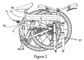
ここで図1に言及すれば、本発明で使用される要素の多くは、車輪、ドライブトレーン、シート、シートポスト、ハンドルバー、ハンドルバーステム、ブレーキ、ペダル、フォーク等、標準的な従来の自転車で見ることができる。これらの要素は周知であるので符号を付けない。図示の通り、ハンドルバー、ステム、フロントフォーク、前輪等を含む操舵アセンブリはヘッドチューブ35によってフロントフレーム1に回転自在に装着されている。ドライブトレーン、後輪及びシートポストはリアフレーム2に装着されることもある。アウタシートチューブ17はフロントフレーム1の構成部品であってよく、リアフレーム2の構成部品であってよいシートチューブ54に同心且つ回転自在に装着される。フロントメインチューブ39は、その上面にロッキングアセンブリ又はロッキングレバーといったいかなる突出物もなく示されている。図示した実施形態において、フロントロック部材3及びロックアセンブリ4はフロントメインチューブ39の下方に装着されており、いかなる構成部品もメインチューブ39より上方に突出しない。フロントロック部材3及びロックアセンブリ4は、自転車を稼動乗車位置に保持するロッキングアセンブリの2つの連結構成部品である。フロントロック部材3はフロントフレーム1に装着されるとしてよく、ロックアセンブリ4はリアフレーム2に装着されるとしてよい。ロックアセンブリ4は、フロントロック部材3及びロックアセンブリ4を一体に固定するために必要な各種可動部品を含むが、これらの部品はフロントフレーム1へ装着することもできよう。次に図2に言及すれば、自転車は折りたたみ位置で示されており、前輪はフロントフォーク37から取外され、ロックアセンブリ4はフロントロック部材3から分離されており、アウタシートチューブ17をシートチューブ54に関して折りたたみ位置に回転させている。図示していないが、各図において本書に記載の構成に関する変更は当業者には明瞭であろう。例えば、複数のサブフレームアセンブリ又は図示のものとは異なる構成から成るフロントフレーム及び/又はリアフレーム、折りたたみ軸及び締結点の位置の変更、車輪径の変更、折りたたみ中に前輪を自転車に締結したままにする実施形態及び、折りたたみ及び締結点以外での非重畳フレームによる他の変更などである。
Referring now to FIG. 1, many of the elements used in the present invention are standard conventional bicycles such as wheels, drivetrains, seats, seatposts, handlebars, handlebar stems, brakes, pedals, forks, etc. Can be seen in These elements are well known and are not labeled. As shown in the figure, a steering assembly including a handle bar, a stem, a front fork, a front wheel and the like is rotatably mounted on the
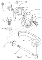
次に図3に言及すれば、大部分の構成部品が装着される主要部材であるロック本体6を含むロックアセンブリ4の分解図が示されている。ロック本体6は、固定ボルト16及びボウルワッシャ24を用いてリアフレーム2(図示せず)に調整可能となるように装着され得る。ロック本体6のスキューア穴44を貫いてスキューア12が装着され、スキューア12はレバー10が回転自在に装着される軸18を保持する。レバー10はカム従動節20に作用するカム面を備えており、転じてカム従動節20はロック本体6のカム作用面62に作用してスキューア12において張力を生じ、それによってねじ込みによってスキューア12に装着される調整ナット14を引っ張る。ウェッジ8は、調整ナット14に装着され、スキューア12が軸方向に動くとウェッジ8もスキューア12とともに動くようにCクリップ28によって調整ナット14に保持されている。レバー10及びスキューア12が軸方向に動くと、ばね22は圧縮され、ウェッジ8はロック本体6に対して移動する。ばね22はまた、カム作用面62を押してウェッジ8をロック本体6方向に偏倚させる。制振ナイロン26は、スキューア12まわりでの調整ナット14の不要な回転を防止する役割を果たす。ウェッジ8はその内面にウェッジ二次的保持面32及びウェッジ一次的保持面34を備えており、ロック本体6は止め面30を備えている。クイックリリースカムが図示されているが、任意の数の他の締結機構を使用可能なことは当業者には明らかであろう。
Referring now to FIG. 3, there is shown an exploded view of the
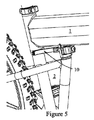
次に図4乃至7に言及すれば、自転車を折りたたむ操作の順序が示されている。図4は、稼動乗車位置における自転車を示しており、レバー10は締結状態にあり、ロックアセンブリ4はフロントロック部材3と締結されている。フロントフレーム1はリアフレーム2と一直線になっている。図5は、レバー10が開かれカム張力が解放されたことを示している。この状態では、フロントフレーム1はまだリアフレーム2と概ね一直線になっており、二次的保持はまだ係合しているが、一次的保持はすでに解放されている。図6は、レバー10がばね22(図示せず)に軸方向に押しつけられてフロントロック部材3がウェッジ8から脱離され、それにより二次的保持を解放するとともにフロントフレーム1がリアフレーム2に対して回転することを示す。図7は、リアフレーム2に対して折りたたみ位置に回転したフロントフレーム1を示している。図4乃至7は、締結機構を解放し自転車を折りたたむためには、図5のように一次的保持を解放し、図6のように二次的保持を解放しなければならないことを例証している。二次的保持システムは、ウェッジ8がロック本体6及びフロントロック部材3の両方を捕捉するようにさせるばね22のために、常に保持位置に留まるように偏倚され得る。このように、自転車が稼動乗車位置にある場合、二次的保持は安全のために保持位置にある。図に記載の実施形態において自転車を折りたたむためには、使用者は二次的保持を脱離させ、自転車の折りたたみの初期行為の間、それを能動的に脱離させておかなければならない。このようにして、使用者は、乗り手になる人に危険となり得る二次的保持が脱離した状態で自転車を放置することはできない。
Referring now to FIGS. 4-7, the sequence of operations for folding a bicycle is shown. FIG. 4 shows the bicycle in the operating boarding position, the
次に図8乃至12に言及すれば、二次的保持システムを備える折りたたみ自転車ロッキングアセンブリの1構成が示されており、二次的保持システムは、自転車が稼動乗車位置にある時は係合位置に偏倚するように構成されており、自転車が稼動乗車位置に展開された時に自動的に係合する。自転車の展開における締結機構の一連の操作を示す。明確さのために、図は下方に向いているが、フロントフレーム1の位置を示すためにフロントメインチューブ39を点線で示している。リアフレーム2は図示していない。フロント及びリアフレームが回転軸15に関して折れる際の順序を示しており、図8は、稼動乗車位置に近づいているが、フロントロック部材3がロックアセンブリ4に係合する前の自転車を示している。レバー10は開位置にあり、自動二次的面5がウェッジ自動二次的面36に係合しようとしている。二次的保持面9及び一次的保持面7は、ウェッジ8のそれぞれの対応する表面とまだ接触していない。図9は、ウェッジ自動二次的面36とまさに接触したところの自動二次的面5を示しており、図10は、自動二次的面5がウェッジ自動二次的面36を押してウェッジ8を右に移動させ、ばね22を圧縮したことを示す。図11は、縁端がフロントロック部材縁端41を越えてばね22が作用した後に左に移動して戻ったウェッジ8を示している。この状態において、二次的保持は二次的保持面9及びリア二次的保持面40がこの時ウェッジ二次的保持面32によって捕捉されているので係合しており、二次的保持面9及びリア二次的保持面40の角度がフロントロック部材3の回転経路の接線に垂直に近いために、フロントロック部材3はウェッジ8が分離を防ぐのでロックアセンブリ4ともはや分離できない。ばね22はウェッジ二次的保持面32及びウェッジ8にフロントロック部材3を保持させ、それにより二次的保持を係合させ続ける役割を果たす。最後に、図12は、レバー10が閉じられて、それによりウェッジ一次的保持面34をカム圧により一次的保持面7及びリア一次的保持面38に押しつけさせることによって一次的保持を係合させることを示している。このようにして、二次的保持は自動的に係合することが示され、引き続き一次的保持は手動で係合されて自転車を稼動乗車位置に締結する。ウェッジ8はこのプロセス中に調整ナット14で左右に移動可能なある程度の能力を有することがわかる。図示の通り、ウェッジ8はフロントロック部材3及びロックアセンブリ4を枢転方向に離れて動かないように一体に締結する。しかし、フロントロック部材3及びロックアセンブリ4が互いに対する垂直面での動きを防止されていることはこの順序には示されていない。これは図19及び20に示す。
Referring now to FIGS. 8-12, one configuration of a folding bicycle locking assembly with a secondary retention system is shown, wherein the secondary retention system is in the engaged position when the bicycle is in an active riding position. The bicycle is automatically engaged when the bicycle is deployed to the operating boarding position. A series of operations of the fastening mechanism in the deployment of the bicycle is shown. For the sake of clarity, the figure is directed downward, but the front
次に図13乃至18に言及すれば、図13及び14にはフロントロック部材3が示されており、フロントロック部材3は締結面13でフロントメインチューブ39の下面に永久的に取付けられ得る。自動二次的面5及びフロントロック部材縁端41を含む二次的保持の自動係合を生じる各種表面が示されている。二次的保持面9も示されている。一次的保持面7も示されている。ここで新たに斜面11が示されており、これは2つの機能を果たすことができる。第1の機能は、ロックアセンブリ4の対応する表面の下方で延出し、乗車中に大きな力を受ける間にフロントロック部材3がロックアセンブリ4に対して垂直方向に持ち上がらないようにフロントロック部材3をロックアセンブリ4に固定することである。こうした力は斜面11を通じて一方のフレームから他方へ伝達される。したがって、斜面11は、乗車中に受ける力をもっぱらスキューア12によって生じさせないシステムを可能にする。斜面11が一次的保持面7からほぼ直角である点に留意することが新規且つ重要である。この相対角度は、後述の通りレバー10の固定中の様々な方向での各種部品の動きを生じる。
Next, referring to FIGS. 13 to 18, the
図15及び16は、ロック本体6の詳細を示しており、リア二次的保持面40及びリア一次的保持面38については図8乃至12の順序においてすでに検討した。ここで新たにリア斜面42が示されており、リア斜面42は、図13及び14に示した斜面11に作用して、乗車中に力を受ける間のフロントロック部材3及びロックアセンブリ4の相対的垂直移動を防止する。また、図15及び16では新たに凸状調整面46、過大穴48及びワッシャ空洞52が示されており、これらは製造公差を考慮するためにリアフレーム2といった自転車フレームにロック本体6を調整可能に装着可能なようにする。このようにして、ロックアセンブリ4の構成部品であるロック本体6は、リアフレーム2の上面に取付けられ得る。回転防止タブ50はリアフレーム2に対するロック本体6の不要な回転を調整可能に防ぐ。フロントロック部材3と同様、ロック本体6は、レバー10の締結中に複数の方向で動きを生じる2つの斜面を互いに約90°の角度で有する。図17は、ウェッジ二次的保持面32と、ウェッジ一次的保持面34と、二次的保持面及び一次的保持面の係合中の正しいアライメントのための中心合わせを可能にするためにウェッジ8のある程度の横移動を許すウェッジスキューア穴66とを備えたウェッジ8を示している。ウェッジ自動二次的面36も示されている。図18は、図示の通り二次的保持面31が接し一次的保持面29が接してフロントロック部材3、ロック本体6及びウェッジ8がどのように一体に嵌着するかを示している。また斜面11がどのようにリア斜面42に接するかも示されている。
15 and 16 show details of the lock body 6 and the rear secondary holding
次に図19及び20に示した順序に言及すれば、折りたたみ機構を備える折りたたみ自転車が好ましく、締結機構は、固定稼動乗車位置に作動する時に、折りたたみ機構に存在するいずれかの組立公差を縮小するようにして折りたたみ機構に力23を加える組立品によって特徴づけられる。これを達成するために、締結機構は、上フレーム1(フロントフレームとして示されているがリアフレームであってもよい)から下方に延びる上部要素3及び下フレーム2(リアフレームとして示されているがフロントフレームであってもよい)から上方に延びる下部要素6よりなるとしてよく、自転車を稼動乗車位置に展開する最中に、上部要素3及び下部要素6は接し、ウェッジ8(図示せず)といった第3の保持要素によって一体に保持される。上部要素3は下部要素の一部分の下方で延出するキャッチ部45を含み、下部要素は上部要素の一部分の上方で延出するキャッチ部68を含む。上部キャッチ部45及び下部キャッチ部68は、自転車が稼動乗車位置へ動かされた時に接する対応する斜面11及び42を有しており、第3の保持要素8(図示せず)は、対応する斜面を押し付け合わせて上部キャッチ部及び上フレーム1を下部キャッチ部及び下フレーム2で引き上げるようにする役割を果たす。上部要素3及び下部要素6は複数の対応する斜面を含むとしてよく、1つの組11及び42は地面に対し概ね平行であり、1つの組38及び7(図示せず)は地面に対し概ね垂直であり、第3の保持要素8は作動装置10及び12によって作動し、当該作動により対応する斜面が水平及び垂直方向で圧縮し締結することになる。これにより、乗車中に受ける横方向の力は一般に作動装置8を介してフロントフレーム1からリアフレーム2へ、またリアフレーム1からフロントフレーム2へ伝達され得る。同様に、乗車中に受ける垂直の力は一般に、作動装置12によってではなく対応する斜面11及び42によって、フロントフレーム1からリアフレーム2へ、またリアフレーム2からフロントフレーム1へ伝達される。これは作動装置12がたいてい可動部材であって強くないので望ましい。要約すれば、ウェッジ8がレバー10及びスキューア12によって作動する時、ウェッジ一次的保持面34は斜め一次的保持面7及びリア一次的保持面38を互いの方へ押し、それにより斜面11及びリアヒンジプリロード面42を互いに対して摺動させる。斜面の組38と34、7と34及び11と42は互いに直角で示されているが、それらが互いに対し他の角度にある表面又は、同様に機能する円錐面といった異なる形状の表面と代替可能なことは当業者には明らかであろう。より詳しくは、図19は、二次的保持は係合しているが、レバー10は開位置にあるので一次的保持システムが係合していない状態の展開位置にある自転車を示している。レバー10を図20に示した閉位置に動かすことにより2つのことを達成できる。第一に、図11及び12に例示した通り一次的保持システムを締結する働きをする。第二に、リアヒンジプリロード面42を斜面11に沿って上方に摺動させ、それによって枢転機構における不要な公差を除去するヒンジプリロード23を生じさせることが可能である。これが生じるのは、リアヒンジプリロード面42に沿った斜面11による下方への摺動がフロントロック部材3を下方に引っ張り、それは転じてフロントメインチューブ39を下方に引っ張り、それによりアウタシートチューブ17にモーメントアーム力を加え、それが転じてブッシング27、アウタシートチューブ17及びシートチューブ54の間に見られるいずれかの製造公差を除去するからである。このようにして、一次的未固定空間19は一次的固定空間21に縮小又は削除される。シートチューブクランプ56は、リアフレーム2の一部でありブッシング27及びアウタシートチューブ17を適位置に保持するシートチューブ54に固定される。また、製造公差を考慮するためにリアフレーム2に対してフロントフレーム1を上下に調整する単数又は複数の垂直調整スペーサ25も示されている。このプロセスは図22及び23に示した断面図で更に例示する。
Referring now to the sequence shown in FIGS. 19 and 20, a folding bicycle with a folding mechanism is preferred, and the fastening mechanism reduces any assembly tolerances present in the folding mechanism when operating in a fixed operating boarding position. Thus characterized by an assembly that applies a
製造公差は必ず存在し、したがってそれらを考慮するシステムを組み込むことはどのような組立品においても重要である。本発明は、異なるフレームに締結され通常は枢転位置からオフセットされる斜面が正しい位置及び角度で接することを要求でき、したがって製造後に角度調整を行える能力は重要である。図24乃至26は、折りたたみ自転車を示しており、締結機構3及び/又は4は、製造公差を考慮するために時々それらをフロント又はリアフレームに対して調整可能とするようにしてフロントフレーム1又はリアフレーム2に取付けられている。これを達成する一方法は図示の通りであって、ロックアセンブリ4は、ねじ穴60にねじ込まれた固定ボルト16を緩め、凸状調整面46を調整ボウル64で摺動させ、ボウルワッシャ24をワッシャ空洞52で摺動させるとともに固定ボルト16を過大穴48内部で所要の位置に移動させることによって、角度的に調整できる。これらの表面が球面であるので角度調整は任意の方向で可能であるが、図24及び25では自転車の車輪に平行な方向で示しているにすぎない。この調整力は、垂直調整スペーサ25を用いた垂直調整と組み合わせると、広範な調整を可能にする。自転車フレームの中心線に平行な方向で調整可能な組立品も、図示していないが当業者には明らかである。
Manufacturing tolerances always exist, and therefore incorporating a system that takes them into account is important in any assembly. The present invention can require that slopes fastened to different frames and normally offset from the pivot position meet at the correct position and angle, so the ability to adjust the angle after manufacture is important. FIGS. 24 to 26 show folding bicycles, in which the
折りたたみ自転車のいずれのロッキングアセンブリでも使いやすさが要求されるので、図27及び28は、一次的保持を解放するためにレバー10を操作した後、二次的保持を解放するために第2の操作がどのように要求されるかを示している。操作の一方法は、回転軸点43でアウタシートチューブ17からずれて枢動するレバー10を押すことによってウェッジ8を前方に動かすことからなる。
Since any locking assembly of a folding bicycle requires ease of use, FIGS. 27 and 28 show the second to release the secondary hold after manipulating the
これらの図全体を通じて、フロントフレーム1は単一のメインチューブとして示されているが、それは、固定式に、枢転若しくは懸垂式に、取外し可能式に、又は折りたたみ自転車に見られるもののような部材が互いに対して可動である方式で、一体に締結される複数のフレーム部材から構成し得ることに留意しなければならない。更に、リアフレーム2は、単一の部材又は、図示の通り一体に固定された複数のフレーム部材又は、自転車サスペンション又は折りたたみ自転車で一般に見られるもののような互いに対して可動である、枢転式、懸垂式又は取外し可能式に一体に締結された複数のフレーム部材から構成してもよい。
Throughout these figures, the
本発明の幅広さを考慮するうえで、用語「部材」、「部分」、「構成部品」、「部品」又は「要素」は、単数形で使用された時、複数の部品を含め複数形も包含するとみなすことができる。用語「よりなる」が使用された時、記載した特徴、構成部品又はステップの包含を指定するように意図しているが、記載していない他の特徴、構成部品又はステップを除外しない。用語「枢転」、「枢動」、「回転」、「折りたたみ」及びそれらの派生語は交換可能に使用され同じ意味を有する。用語「ロック」、「締結」及びそれらの派生語は交換可能に使用され同じ意味を有する。用語「係合した」は一体に締結されていることを意味する。用語「一次的保持」は、一次的ロックであるシステムを指す。用語「二次的保持」は、一次的保持が解放又は故障した場合に組立品を保持又は固定するシステムを指す。 In consideration of the breadth of the present invention, the terms “member”, “part”, “component”, “part” or “element” may be used in the singular to include plural parts. It can be regarded as including. When the term “consisting of” is used, it is intended to specify the inclusion of the described feature, component or step, but does not exclude other features, components or steps not described. The terms “pivot”, “pivot”, “rotate”, “fold” and their derivatives are used interchangeably and have the same meaning. The terms “lock”, “fastening” and their derivatives are used interchangeably and have the same meaning. The term “engaged” means fastened together. The term “primary hold” refers to a system that is a primary lock. The term “secondary hold” refers to a system that holds or secures an assembly when the primary hold is released or fails.
選定した実施形態だけが本発明を例示するために選択されたが、添付クレームにおいて規定される本発明の範囲を逸脱することなく様々な変更及び修正がここで行い得ることはこの開示から当業者には明らかである。更に、本発明に従った実施形態の上述の説明は、添付クレーム及びそれらの等価物によって規定される本発明を制限する目的ではなく、例示のためだけに提示されている。 Although only selected embodiments have been selected to illustrate the present invention, it will be apparent to those skilled in the art from this disclosure that various changes and modifications can be made herein without departing from the scope of the invention as defined in the appended claims. Is obvious. Furthermore, the foregoing descriptions of embodiments according to the present invention are presented for purposes of illustration only and not for the purpose of limiting the invention as defined by the appended claims and their equivalents.
1 フロントフレーム、上フレーム
2 リアフレーム、下フレーム
3 フロントロック部材、上部要素、締結機構
4 ロックアセンブリ、締結機構
5 自動二次的面
6 ロック本体、下部要素
7 一次的保持面、斜め一次的保持面
8 ウェッジ、第3の保持要素、作動装置
9 二次的保持面
10 レバー、作動装置
11 斜面
12 スキューア、作動装置
13 締結面
14 調整ナット
15 共通回転軸
16 固定ボルト
17 フレーム部材、アウタシートチューブ
18 軸
19 一次的未固定空間
20 カム従動節
21 一次的固定空間
22 ばね
23 力、ヒンジプリロード
24 ボウルワッシャ
25 垂直調整スペーサ
26 制振ナイロン
27 ブッシング
28 Cクリップ
29 一次的保持面
30 止め面
31 二次的保持面
32 ウェッジ二次的保持面
34 ウェッジ一次的保持面
35 ヘッドチューブ
36 ウェッジ自動二次的面
37 フロントフォーク
38 リア一次的保持面
39 フロントメインチューブ
40 リア二次的保持面
41 フロントロック部材縁端
42 斜面、リア斜面、リアヒンジプリロード面
43 回転軸点
44 スキューア穴
45 キャッチ部
46 凸状調整面
48 過大穴
50 回転防止タブ
52 ワッシャ空洞
54 シートチューブ、フレーム部材
56 シートチューブクランプ
60 ねじ穴
62 カム作用面
64 調整ボウル
66 ウェッジスキューア穴
68 キャッチ部
DESCRIPTION OF
Claims (17)
前記フロントフレーム及び前記リアフレームは、折りたたむ時に各フレームが前記共通回転軸および前記締結機構以外で他方のフレームの構造部材に接触することなく前記共通回転軸に関して回転可能なように配向されており、前記フロントフレーム及び前記リアフレームの構造部材は、前記共通回転軸および前記締結機構以外で互いに回避し合い重ならず、前記フロントフレームは前記リアフレームの上方に位置し、
前記共通回転軸はシートチューブ又はその近傍に位置し、
前記締結機構は前記シートチューブの前で当該シートチューブ上を除くその近傍に位置しており、
前記締結機構は、前記フロントフレームの最上面より上方に位置しない部材の作動によって前記フロントフレーム及び前記リアフレームを前記自転車の展開状態に対応する固定稼動乗車位置に締結するために配置された、折りたたみ自転車。 A folding bicycle comprising a seat tube, a front frame for mounting a front wheel fork assembly, a rear frame for mounting a rear wheel, a common rotating shaft, and a fastening mechanism,
The front frame and the rear frame are oriented so that each frame can rotate with respect to the common rotation axis without contacting the structural member of the other frame other than the common rotation axis and the fastening mechanism when folded. The structural members of the front frame and the rear frame avoid and overlap each other except for the common rotating shaft and the fastening mechanism, and the front frame is located above the rear frame,
The common rotation axis is located at or near the seat tube,
The fastening mechanism is located in front of the seat tube and in the vicinity thereof except on the seat tube,
The folding mechanism is arranged to fasten the front frame and the rear frame to a fixed operation boarding position corresponding to the unfolded state of the bicycle by operation of a member not located above the uppermost surface of the front frame. bicycle.
Applications Claiming Priority (3)
| Application Number | Priority Date | Filing Date | Title |
|---|---|---|---|
| US14/805,563 US9834275B2 (en) | 2015-07-22 | 2015-07-22 | Non-overlapping frame folding bike |
| US14/805,563 | 2015-07-22 | ||
| PCT/US2016/042523 WO2017015121A1 (en) | 2015-07-22 | 2016-07-15 | Non-overlapping frame folding bike |
Publications (2)
| Publication Number | Publication Date |
|---|---|
| JP2018527251A JP2018527251A (en) | 2018-09-20 |
| JP6572386B2 true JP6572386B2 (en) | 2019-09-11 |
Family
ID=57835171
Family Applications (1)
| Application Number | Title | Priority Date | Filing Date |
|---|---|---|---|
| JP2018518733A Active JP6572386B2 (en) | 2015-07-22 | 2016-07-15 | Non-overlapping frame folding bike |
Country Status (6)
| Country | Link |
|---|---|
| US (1) | US9834275B2 (en) |
| EP (1) | EP3325331A4 (en) |
| JP (1) | JP6572386B2 (en) |
| CN (1) | CN107922030B (en) |
| TW (1) | TW201718320A (en) |
| WO (1) | WO2017015121A1 (en) |
Families Citing this family (6)
| Publication number | Priority date | Publication date | Assignee | Title |
|---|---|---|---|---|
| US10150529B2 (en) * | 2014-06-06 | 2018-12-11 | Bignay, Inc. | Vertically folding bicycle with locking mechanism |
| US10328992B2 (en) * | 2016-10-12 | 2019-06-25 | Zakarias LAXSTRÖM | Bicycle |
| US10814931B1 (en) * | 2017-06-26 | 2020-10-27 | Burley Design Llc | Bicycle skewer with bicycle trailer couplers |
| US10384556B1 (en) * | 2018-03-12 | 2019-08-20 | Honda Motor Co., Ltd. | Multi-vehicle type device having battery packs |
| WO2020092724A1 (en) * | 2018-11-02 | 2020-05-07 | Newcycle, Inc. | Folding vehicle |
| USD964218S1 (en) * | 2020-03-14 | 2022-09-20 | Thomas Martin Piszkin | Electric-assist adult strider |
Family Cites Families (40)
| Publication number | Priority date | Publication date | Assignee | Title |
|---|---|---|---|---|
| US518330A (en) | 1894-04-17 | Necticut | ||
| US569354A (en) | 1896-10-13 | Folding bicycle | ||
| US613244A (en) | 1898-11-01 | Bicycle | ||
| NL134153C (en) | 1969-08-20 | |||
| GB1580048A (en) | 1976-05-07 | 1980-11-26 | Brompton Bicycle Ltd | Folding bicycles |
| US4067589A (en) | 1976-05-21 | 1978-01-10 | Hon David T | Foldable bicycle |
| US4417745A (en) * | 1981-03-16 | 1983-11-29 | Shomo Robert D | Folding bicycle |
| US4448437A (en) | 1981-08-31 | 1984-05-15 | Montague Harry D | Foldable bicycle |
| HU185269B (en) | 1982-03-16 | 1984-12-28 | Lajos Csizmadia | Collapsible bicycle |
| US4579360A (en) | 1983-06-11 | 1986-04-01 | Bridgestone Cycle Co., Ltd. | Foldable bicycle frame |
| US4824130A (en) | 1987-10-19 | 1989-04-25 | David Chiu | Mini foldable cycle |
| US4900047A (en) | 1988-10-28 | 1990-02-13 | Harry Montague | Foldable bicycle |
| US5222751A (en) | 1991-01-22 | 1993-06-29 | Chen Robert W P | Foldable bicycle frame |
| DE4207771C2 (en) | 1992-03-11 | 1996-05-15 | Robert W P Chen | Foldable bike |
| GB2280878A (en) | 1993-08-10 | 1995-02-15 | Ching Tsung Yeh | Foldable bicycle frame. |
| BR9710262A (en) * | 1996-07-09 | 2000-01-18 | Friedrich Grimm | Two-wheel vehicle traveling in a single line. |
| US5975551A (en) * | 1997-07-18 | 1999-11-02 | Montague Corporation | Folding frame bicycle |
| JP3058905U (en) * | 1997-11-21 | 1999-06-22 | 三千里自轉車工業株式會社 | Folding bike |
| US6595536B1 (en) | 1999-12-29 | 2003-07-22 | Timothy R. Tucker | Collapsible vehicle |
| CN1315686A (en) | 2000-03-31 | 2001-10-03 | 梁子兴 | Chinese-character digital code input method |
| EP1184274B1 (en) | 2000-08-31 | 2005-11-02 | Honda Giken Kogyo Kabushiki Kaisha | Bicycle |
| CN2467382Y (en) * | 2001-01-12 | 2001-12-26 | 韩德玮 | Folding fastening device for foldable bicycle |
| DE10127614B4 (en) | 2001-06-07 | 2004-12-30 | Iko Sportartikel-Handels-Gmbh | bicycle |
| US6523223B2 (en) | 2001-06-29 | 2003-02-25 | Ping-Tien Wang | Hinge for a foldable bicycle |
| ATE290979T1 (en) | 2001-09-28 | 2005-04-15 | Ritchey Designs Inc | A SYSTEM AND METHOD FOR CONNECTING PARTS |
| US7722070B2 (en) | 2001-09-28 | 2010-05-25 | Ritchey Designs, Inc. | System and method for connecting parts |
| TW573661U (en) | 2002-07-15 | 2004-01-21 | Hung-Chang Chao | A kitset bicycle combined with different stress directions |
| JP2004058912A (en) * | 2002-07-31 | 2004-02-26 | Bridgestone Cycle Co | Folding bicycle |
| US6886845B2 (en) | 2003-04-25 | 2005-05-03 | Hung-Chang Chao | Detachable bicycle |
| CN2664991Y (en) * | 2003-12-06 | 2004-12-22 | 徐达来 | Folding apparatus for folding bicycles |
| US7290956B2 (en) * | 2004-10-01 | 2007-11-06 | Studio Moderna Sa | Releasable securing apparatus and method of using same |
| US7121567B1 (en) | 2005-04-25 | 2006-10-17 | Albert J Gaea | Bicycle having front and rear rotative wheel frames with actuatable means for engaging and disengaging the rear wheel frame rotation |
| JP2006335143A (en) * | 2005-05-31 | 2006-12-14 | Juda Mach Ind Co Ltd | Folding bicycle |
| DE202006007546U1 (en) * | 2006-05-10 | 2006-09-14 | Votex Gmbh | Folding bicycle for compact storage has rear wheel fork part able to turn on saddle frame tube |
| US8123243B2 (en) | 2009-12-18 | 2012-02-28 | Ho William M | Foldable bicycle |
| US8141893B2 (en) | 2010-01-11 | 2012-03-27 | Lin Wen Teng | Folding apparatus for a bicycle frame |
| FR2969980B1 (en) | 2010-12-31 | 2013-11-22 | Decathlon Sa | FOLDING BICYCLE |
| CN202156506U (en) | 2011-08-01 | 2012-03-07 | 大行科技(深圳)有限公司 | Quick folding bicycle |
| CN203681784U (en) * | 2013-09-09 | 2014-07-02 | 肖友明 | Portable multi-functional foldable bicycle |
| CN105882838A (en) * | 2014-10-22 | 2016-08-24 | 刘德武 | Folding bicycle frame |
-
2015
- 2015-07-22 US US14/805,563 patent/US9834275B2/en active Active
-
2016
- 2016-07-15 CN CN201680042953.1A patent/CN107922030B/en active Active
- 2016-07-15 EP EP16828312.5A patent/EP3325331A4/en not_active Withdrawn
- 2016-07-15 WO PCT/US2016/042523 patent/WO2017015121A1/en unknown
- 2016-07-15 JP JP2018518733A patent/JP6572386B2/en active Active
- 2016-07-20 TW TW105122828A patent/TW201718320A/en unknown
Also Published As
| Publication number | Publication date |
|---|---|
| US9834275B2 (en) | 2017-12-05 |
| CN107922030A (en) | 2018-04-17 |
| EP3325331A4 (en) | 2019-03-13 |
| TW201718320A (en) | 2017-06-01 |
| EP3325331A1 (en) | 2018-05-30 |
| WO2017015121A1 (en) | 2017-01-26 |
| JP2018527251A (en) | 2018-09-20 |
| CN107922030B (en) | 2019-09-03 |
| US20170021892A1 (en) | 2017-01-26 |
Similar Documents
| Publication | Publication Date | Title |
|---|---|---|
| JP6572386B2 (en) | Non-overlapping frame folding bike | |
| US7665928B2 (en) | Quick release camming mechanism | |
| TWI434787B (en) | Quick release bicycle wheel | |
| US7614631B2 (en) | Fork release mechanism of bicycle | |
| EP3172111B1 (en) | Stroller | |
| CN102009684B (en) | Energy absorbing device for a collapsible steering column assembly | |
| CN104080687B (en) | Doll carriage | |
| US5269550A (en) | Mountain bike | |
| US7090308B2 (en) | Axle assembly for mounting a wheel to a vehicle | |
| US9284008B2 (en) | Folding kick scooter | |
| US8342574B2 (en) | Device assisting with the locking of a steering column | |
| US20080088113A1 (en) | Method and device for connecting structural parts | |
| EP3174782B1 (en) | Foldable bicycle frame | |
| WO1999003723A1 (en) | Folding frame bicycle | |
| TWM271802U (en) | Hheight adjustment mechanism installed in between the front fork and the handlebar stem of bike | |
| DE202010015823U1 (en) | Fahrradfederungseinstellungsjustieranordnung | |
| US20180311087A1 (en) | Folding wheelchair | |
| US20110089661A1 (en) | Bicycle Axle Assembly | |
| EP2974962A1 (en) | Fixation device comprising a toggle joint, for an aircraft seat | |
| WO2015166000A1 (en) | Bicycle frame | |
| DE102006029781A1 (en) | Method and arrangement for fixing a shock absorber for a bicycle | |
| WO2021094092A1 (en) | Hitching device designed to be fitted on a scooter | |
| CN220535854U (en) | Folding device and scooter | |
| EP4057972B1 (en) | Connection system for connecting a wheelchair to a scooter which is provided with at least one motorised wheel | |
| JP4133662B2 (en) | Bearing structure of head pipe for folding motorcycle |
Legal Events
| Date | Code | Title | Description |
|---|---|---|---|
| A521 | Request for written amendment filed |
Free format text: JAPANESE INTERMEDIATE CODE: A523 Effective date: 20180410 |
|
| A621 | Written request for application examination |
Free format text: JAPANESE INTERMEDIATE CODE: A621 Effective date: 20180410 |
|
| A871 | Explanation of circumstances concerning accelerated examination |
Free format text: JAPANESE INTERMEDIATE CODE: A871 Effective date: 20180410 |
|
| A975 | Report on accelerated examination |
Free format text: JAPANESE INTERMEDIATE CODE: A971005 Effective date: 20180904 |
|
| A131 | Notification of reasons for refusal |
Free format text: JAPANESE INTERMEDIATE CODE: A131 Effective date: 20180911 |
|
| A521 | Request for written amendment filed |
Free format text: JAPANESE INTERMEDIATE CODE: A523 Effective date: 20181211 |
|
| A131 | Notification of reasons for refusal |
Free format text: JAPANESE INTERMEDIATE CODE: A131 Effective date: 20190226 |
|
| A521 | Request for written amendment filed |
Free format text: JAPANESE INTERMEDIATE CODE: A523 Effective date: 20190524 |
|
| TRDD | Decision of grant or rejection written | ||
| A01 | Written decision to grant a patent or to grant a registration (utility model) |
Free format text: JAPANESE INTERMEDIATE CODE: A01 Effective date: 20190716 |
|
| A61 | First payment of annual fees (during grant procedure) |
Free format text: JAPANESE INTERMEDIATE CODE: A61 Effective date: 20190809 |
|
| R150 | Certificate of patent or registration of utility model |
Ref document number: 6572386 Country of ref document: JP Free format text: JAPANESE INTERMEDIATE CODE: R150 |
|
| R250 | Receipt of annual fees |
Free format text: JAPANESE INTERMEDIATE CODE: R250 |
|
| R250 | Receipt of annual fees |
Free format text: JAPANESE INTERMEDIATE CODE: R250 |