JP6571641B2 - Method and apparatus for charging, melting and supplying fluid from fluid supply apparatus - Google Patents
Method and apparatus for charging, melting and supplying fluid from fluid supply apparatus Download PDFInfo
- Publication number
- JP6571641B2 JP6571641B2 JP2016519981A JP2016519981A JP6571641B2 JP 6571641 B2 JP6571641 B2 JP 6571641B2 JP 2016519981 A JP2016519981 A JP 2016519981A JP 2016519981 A JP2016519981 A JP 2016519981A JP 6571641 B2 JP6571641 B2 JP 6571641B2
- Authority
- JP
- Japan
- Prior art keywords
- container
- fluid
- hopper
- loading chamber
- melter
- Prior art date
- Legal status (The legal status is an assumption and is not a legal conclusion. Google has not performed a legal analysis and makes no representation as to the accuracy of the status listed.)
- Active
Links
Images


Classifications
-
- B—PERFORMING OPERATIONS; TRANSPORTING
- B05—SPRAYING OR ATOMISING IN GENERAL; APPLYING FLUENT MATERIALS TO SURFACES, IN GENERAL
- B05C—APPARATUS FOR APPLYING FLUENT MATERIALS TO SURFACES, IN GENERAL
- B05C11/00—Component parts, details or accessories not specifically provided for in groups B05C1/00 - B05C9/00
- B05C11/10—Storage, supply or control of liquid or other fluent material; Recovery of excess liquid or other fluent material
- B05C11/1042—Storage, supply or control of liquid or other fluent material; Recovery of excess liquid or other fluent material provided with means for heating or cooling the liquid or other fluent material in the supplying means upstream of the applying apparatus
-
- B—PERFORMING OPERATIONS; TRANSPORTING
- B05—SPRAYING OR ATOMISING IN GENERAL; APPLYING FLUENT MATERIALS TO SURFACES, IN GENERAL
- B05C—APPARATUS FOR APPLYING FLUENT MATERIALS TO SURFACES, IN GENERAL
- B05C11/00—Component parts, details or accessories not specifically provided for in groups B05C1/00 - B05C9/00
- B05C11/10—Storage, supply or control of liquid or other fluent material; Recovery of excess liquid or other fluent material
- B05C11/1047—Apparatus or installations for supplying liquid or other fluent material comprising a buffer container or an accumulator between the supply source and the applicator
-
- B—PERFORMING OPERATIONS; TRANSPORTING
- B29—WORKING OF PLASTICS; WORKING OF SUBSTANCES IN A PLASTIC STATE IN GENERAL
- B29B—PREPARATION OR PRETREATMENT OF THE MATERIAL TO BE SHAPED; MAKING GRANULES OR PREFORMS; RECOVERY OF PLASTICS OR OTHER CONSTITUENTS OF WASTE MATERIAL CONTAINING PLASTICS
- B29B13/00—Conditioning or physical treatment of the material to be shaped
- B29B13/02—Conditioning or physical treatment of the material to be shaped by heating
- B29B13/022—Melting the material to be shaped
-
- B—PERFORMING OPERATIONS; TRANSPORTING
- B66—HOISTING; LIFTING; HAULING
- B66C—CRANES; LOAD-ENGAGING ELEMENTS OR DEVICES FOR CRANES, CAPSTANS, WINCHES, OR TACKLES
- B66C1/00—Load-engaging elements or devices attached to lifting or lowering gear of cranes or adapted for connection therewith for transmitting lifting forces to articles or groups of articles
- B66C1/10—Load-engaging elements or devices attached to lifting or lowering gear of cranes or adapted for connection therewith for transmitting lifting forces to articles or groups of articles by mechanical means
- B66C1/101—Load-engaging elements or devices attached to lifting or lowering gear of cranes or adapted for connection therewith for transmitting lifting forces to articles or groups of articles by mechanical means for containers
-
- B—PERFORMING OPERATIONS; TRANSPORTING
- B05—SPRAYING OR ATOMISING IN GENERAL; APPLYING FLUENT MATERIALS TO SURFACES, IN GENERAL
- B05C—APPARATUS FOR APPLYING FLUENT MATERIALS TO SURFACES, IN GENERAL
- B05C11/00—Component parts, details or accessories not specifically provided for in groups B05C1/00 - B05C9/00
- B05C11/11—Vats or other containers for liquids or other fluent materials
-
- Y—GENERAL TAGGING OF NEW TECHNOLOGICAL DEVELOPMENTS; GENERAL TAGGING OF CROSS-SECTIONAL TECHNOLOGIES SPANNING OVER SEVERAL SECTIONS OF THE IPC; TECHNICAL SUBJECTS COVERED BY FORMER USPC CROSS-REFERENCE ART COLLECTIONS [XRACs] AND DIGESTS
- Y10—TECHNICAL SUBJECTS COVERED BY FORMER USPC
- Y10T—TECHNICAL SUBJECTS COVERED BY FORMER US CLASSIFICATION
- Y10T137/00—Fluid handling
- Y10T137/0318—Processes
- Y10T137/0391—Affecting flow by the addition of material or energy
-
- Y—GENERAL TAGGING OF NEW TECHNOLOGICAL DEVELOPMENTS; GENERAL TAGGING OF CROSS-SECTIONAL TECHNOLOGIES SPANNING OVER SEVERAL SECTIONS OF THE IPC; TECHNICAL SUBJECTS COVERED BY FORMER USPC CROSS-REFERENCE ART COLLECTIONS [XRACs] AND DIGESTS
- Y10—TECHNICAL SUBJECTS COVERED BY FORMER USPC
- Y10T—TECHNICAL SUBJECTS COVERED BY FORMER US CLASSIFICATION
- Y10T137/00—Fluid handling
- Y10T137/6416—With heating or cooling of the system
Description
以下の記載は、内容物を含む容器を装填し、その内容物を溶融し、その溶融した内容物すなわち流体を物品への流体塗布装置に供給する装置に関する。 The following description relates to an apparatus for loading a container containing contents, melting the contents, and supplying the molten contents or fluid to a fluid application device for articles.
従来のホットメルトシステムは、ホットメルト接着剤を溶融する溶融ユニットと、接着剤を物品に塗布する塗布装置とを備える。通常、溶融ユニットは、塗布装置に流体接続され、溶融した接着剤を塗布装置に供給する。 A conventional hot melt system includes a melting unit that melts a hot melt adhesive and a coating device that applies the adhesive to an article. Usually, the melting unit is fluidly connected to the applicator and supplies the molten adhesive to the applicator.
溶融ユニットは、最初は固体形態で供給されるホットメルト接着剤を収めるように構成されている。通常、固体ホットメルト接着剤は55ガロンドラム缶等の容器に収容され、この容器が溶融ユニットに装填される。溶融ユニットに装填するために、通常、ドラム缶はプラットフォーム上または溶融ユニットの支持構造内の他の表面上に配置される。ドラム缶の上端は開口し、ホットメルト接着剤を露出している。 The melting unit is configured to contain a hot melt adhesive that is initially supplied in solid form. Typically, the solid hot melt adhesive is contained in a container such as a 55 gallon drum, and this container is loaded into the melting unit. To load the melting unit, drums are typically placed on the platform or other surface within the support structure of the melting unit. The upper end of the drum can is opened to expose the hot melt adhesive.
溶融ユニットは、加熱部材をドラム缶の開口端を通してホットメルト接着剤内に移動させる駆動機構を備えることができる。通常、駆動機構は、例えば油圧駆動とすることができるピストンシステムである。通常、加熱部材は、例えばピストンアセンブリによってホットメルト接着剤内に移動されるかまたはホットメルト接着剤と接触させられるプラテンまたはシリンダーの形態のプランジャーである。加熱部材は、接着剤に接触し、接着剤を溶融させる。溶融した接着剤は、塗布装置との使用に向けてドラム缶から取り出すことができる。 The melting unit can include a drive mechanism that moves the heating member through the open end of the drum into the hot melt adhesive. Typically, the drive mechanism is a piston system that can be hydraulically driven, for example. Typically, the heating member is a plunger in the form of a platen or cylinder that is moved into or contacted with the hot melt adhesive, for example by a piston assembly. The heating member contacts the adhesive and melts the adhesive. The molten adhesive can be removed from the drum for use with the applicator.
空のドラム缶を交換するために、溶融ユニットは停止される。すなわち、ピストンがドラム缶から引き抜かれ、ドラム缶が除去され、次に満タンのホットメルト接着剤ドラム缶と交換される。この時間中、塗布装置も停止される場合がある。そのため、ホットメルト接着剤ドラム缶が交換される間、溶融した接着剤を物品に塗布することができない状況が発生する可能性がある。すなわち、溶融ユニット内のホットメルト接着剤ドラム缶を交換することは、溶融した接着剤の塗布装置への流れを中断し、それにより物品への接着剤の塗布を中断する可能性がある。従って、ホットメルト接着剤ドラム缶を交換するのにシステムの運転停止またはアイドリングが必要とされる可能性がある。結果として、溶融ユニットおよび塗布装置の不連続な動作に起因して、製造時間が増大する可能性がある。 In order to replace the empty drum, the melting unit is stopped. That is, the piston is withdrawn from the drum, the drum is removed, and then replaced with a full hot melt adhesive drum. During this time, the coating apparatus may also be stopped. Therefore, a situation may occur in which the molten adhesive cannot be applied to the article while the hot melt adhesive drum can be replaced. That is, replacing the hot melt adhesive drum in the melting unit can interrupt the flow of molten adhesive to the applicator, thereby interrupting the application of the adhesive to the article. Thus, system outage or idling may be required to replace hot melt adhesive drums. As a result, manufacturing time can be increased due to discontinuous operation of the melting unit and the applicator.
いくつかのホットメルトシステムは、2つ以上の個々の溶融ユニットを備えることができる。そのため、1つの溶融ユニット内のドラム缶が空になった場合、別の溶融ユニット内の別の接着剤ドラム缶からホットメルト接着剤を溶融して取り出すことができる。この構成では、接着剤を別のドラム缶から取り出して塗布装置に供給しながら、空のドラム缶を交換することができる。従って、塗布装置に対して、溶融した接着剤の安定した供給を行うことができる。 Some hot melt systems can include two or more individual melting units. Therefore, when the drum can in one melting unit becomes empty, the hot melt adhesive can be melted and taken out from another adhesive drum can in another melting unit. In this configuration, the empty drum can can be replaced while the adhesive is taken out from another drum can and supplied to the coating apparatus. Therefore, it is possible to stably supply the molten adhesive to the coating apparatus.
しかしながら、この構成は、余剰の構成要素を必要とするとともに複雑性を増大させる。例えば、上述のように、この構成は、1つではなく2つ以上の溶融ユニットを使用し、追加のポンプおよび溶融した接着剤を塗布装置に供給するための他の関連機器の実装を必要とする。 However, this configuration requires extra components and increases complexity. For example, as described above, this configuration uses two or more melting units instead of one, and requires the implementation of additional pumps and other related equipment for supplying molten adhesive to the applicator. To do.
ホッパーの内部に加熱表面を有する受け器を形成するようにした、より小型の溶融ユニットが既知である。供給されるホットメルト接着剤を必要に応じてホッパーに加え、溶融して送出することができる。しかしながら、この装置では、ホッパーは、ホットメルト接着剤の55ガロンドラム缶を収めるのに適していない。むしろ、ホッパーは、より少量のホットメルト接着剤、例えば削り粉またはペレットを許容するようなサイズである。そのため、このタイプの装置との使用に好適な供給を提供するには、ホットメルト接着剤スラグの余剰な処理が必要となる。さらに、装置のサイズが制限されているので、ホッパーは頻繁に充填する必要があり、労働費用が増大する可能性がある。 Smaller melting units are known in which a receptacle with a heating surface is formed inside the hopper. The hot melt adhesive to be supplied can be added to the hopper as needed and melted and sent out. However, in this apparatus, the hopper is not suitable for containing a 55 gallon drum of hot melt adhesive. Rather, the hopper is sized to allow a smaller amount of hot melt adhesive, such as shavings or pellets. Therefore, excessive processing of hot melt adhesive slag is required to provide a suitable supply for use with this type of device. Furthermore, due to the limited size of the device, the hopper needs to be filled frequently, which can increase labor costs.
さらに、ホットメルトシステムが設置される施設において、車両、クレーン、人、または他の移動装置若しくは移動機器がホットメルトシステムの近位を通過する場合がある。移動装置または移動物体がホットメルトシステム若しくはドラム缶の外側部分または露出部分と不慮に接触し得る可能性があり、ドラム缶またはホットメルト装置の外側部分を損傷する可能性がある。さらに、ホットメルト接着剤は、ドラム缶内で溶融される際に周囲環境に露出される可能性があり、いくつかの場合において、泡立つかまたは飛散してその近位にある物体と接触する可能性がある。 In addition, vehicles, cranes, people, or other mobile devices or equipment may pass proximal to the hot melt system at the facility where the hot melt system is installed. The moving device or moving object may be inadvertently in contact with the outer or exposed portion of the hot melt system or drum, and may damage the outer portion of the drum or hot melt device. In addition, hot melt adhesives can be exposed to the surrounding environment when melted in drums, and in some cases can foam or splatter and come into contact with objects proximate to them. There is.
従って、流体の連続送出を提供するとともに接着剤を移送および/または溶融するための封鎖領域を提供することができる流体供給装置を提供することが望ましい。さらに、流体供給装置であって、本装置から供給される流体を、異なる計量装置または塗布装置に対して個々に独立して計量することができる流体供給装置を提供することが望ましい。 Accordingly, it would be desirable to provide a fluid supply device that can provide a continuous delivery of fluid and a sealed area for transferring and / or melting the adhesive. Furthermore, it is desirable to provide a fluid supply device that is capable of individually and independently metering fluid supplied from the device to different metering or coating devices.
1つの態様によれば、流体供給装置が提供される。本流体供給装置は、装填室およびホッパーを備えるメルターを備える。ホッパーは装填室と連通して配置されている。装填室は、開口と内部に配置された1または複数の第1の加熱素子とを備える。ホッパーの内部には第2の加熱素子が配置されている。また、本流体供給装置は、内容物が収容されている容器を第1の方向に所定の高さまで持ち上げ、容器を第2の方向に、メルターに対して遠隔の位置から装填室内部の位置まで移動させる容器ハンドリングシステムを備える。アクセス領域が、メルターに隣接する周辺部を有し、アクセス領域によって形成される内部領域へのアクセスを可能にするアクセス部を有する。ポンプシステムがホッパーと流体連通して配置される。ポンプシステムは、少なくとも1つのポンプと、ホッパーと流体連通する少なくとも1つの入口と、少なくとも1つの送出ポートとを備える。装填室は、開口を通して容器を受容するように構成されている。1または複数の可撓性加熱素子は、容器内の内容物を加熱するように構成されている。ホッパーは、容器から内容物を受け取り、内容物を溶融して流体を準備するように構成され、ポンプシステムは、ホッパーから1または複数の遠隔に配置された計量ステーションまたは流体塗布装置に流体を供給するように構成されている。 According to one aspect, a fluid supply apparatus is provided. The fluid supply apparatus includes a melter including a loading chamber and a hopper. The hopper is disposed in communication with the loading chamber. The loading chamber includes an opening and one or more first heating elements disposed therein. A second heating element is disposed inside the hopper. The fluid supply device also lifts the container containing the contents in the first direction to a predetermined height, and moves the container in the second direction from a position remote from the melter to a position inside the loading chamber. A moving container handling system is provided. The access region has a peripheral portion adjacent to the melter and has an access portion that allows access to an internal region formed by the access region. A pump system is placed in fluid communication with the hopper. The pump system includes at least one pump, at least one inlet in fluid communication with the hopper, and at least one delivery port. The loading chamber is configured to receive a container through the opening. The one or more flexible heating elements are configured to heat the contents in the container. The hopper is configured to receive the contents from the container and melt the contents to prepare the fluid, and the pump system supplies fluid from the hopper to one or more remotely located metering stations or fluid application devices Is configured to do.
別の態様によれば、メルターと、ポンプシステムと、容器ハンドリングシステムとを備える流体供給装置が提供される。メルターは装填室およびホッパーを備え、ホッパーは装填室と連通して配置されている。装填室は、開口と、開口を横切って選択的に移動可能なドアと、装填室内部に配置された1または複数の可撓性加熱素子とを備える。ホッパーの内部には第2の加熱素子が配置されている。ポンプシステムは、ホッパーと流体連通し、流体をホッパーから1または複数の遠隔に配置された流体塗布装置または計量装置に供給するように構成されている。容器ハンドリングシステムは、容器を持ち上げ、容器をメルターに対して遠隔の位置から装填室内部の位置に移動させるように構成されている。装填室はホッパーの上方に配置されている。 According to another aspect, a fluid supply apparatus is provided that includes a melter, a pump system, and a container handling system. The melter includes a loading chamber and a hopper, and the hopper is disposed in communication with the loading chamber. The loading chamber includes an opening, a door that is selectively movable across the opening, and one or more flexible heating elements disposed within the loading chamber. A second heating element is disposed inside the hopper. The pump system is in fluid communication with the hopper and is configured to supply fluid to one or more remotely located fluid application or metering devices from the hopper. The container handling system is configured to lift the container and move the container from a position remote to the melter to a position within the loading chamber. The loading chamber is disposed above the hopper.
更に別の態様によれば、流体供給装置を動作させる方法が提供される。流体供給装置は、装填室およびホッパーを備えるメルターを備える。ホッパーは装填室と連通して配置されている。装填室は、開口と装填室内部に配置された1または複数の加熱素子とを備える。ホッパーの内部には第2の加熱素子が配置されている。容器ハンドリングシステムが、内容物が収容されている容器を第1の方向に所定の高さまで持ち上げ、容器を第2の方向に、メルターに対して遠隔の位置から装填室内部の位置まで移動させるように構成されている。ポンプシステムが、ホッパーと連通して配置されている。ポンプシステムは、少なくとも1つのポンプと少なくとも1つの送出ポートとを備える。本方法は、容器を所定の高さまで持ち上げることと、容器をメルターに対して遠隔の位置から装填室内部の位置に移動させることと、装填室のドアを開位置から閉位置に移動させることと、1または複数の加熱素子を受容位置から加熱位置に移動させることと、1または複数の加熱素子にエネルギー付与して容器および容器に収容されている内容物を加熱することと、容器の内容物をホッパーに受け取ることと、ホッパー内の内容物を溶融して流体を準備することと、流体をホッパーから送出することと、少なくとも1つの圧力調節弁を用いて、ホッパーから送出される流体の圧力を調節することとを含む。 According to yet another aspect, a method for operating a fluid supply apparatus is provided. The fluid supply device includes a melter including a loading chamber and a hopper. The hopper is disposed in communication with the loading chamber. The loading chamber includes an opening and one or more heating elements disposed within the loading chamber. A second heating element is disposed inside the hopper. A container handling system lifts the container containing the contents in a first direction to a predetermined height and moves the container in a second direction from a position remote from the melter to a position inside the loading chamber. It is configured. A pump system is disposed in communication with the hopper. The pump system includes at least one pump and at least one delivery port. The method includes lifting the container to a predetermined height, moving the container from a position remote from the melter to a position within the loading chamber, and moving the loading chamber door from an open position to a closed position. Moving one or more heating elements from a receiving position to a heating position, applying energy to the one or more heating elements to heat the container and the contents contained in the container, and the contents of the container The hopper, melting the contents in the hopper to prepare the fluid, delivering the fluid from the hopper, and using at least one pressure regulating valve to pressure the fluid delivered from the hopper Adjusting.
本開示の他の目的、特徴および利点は、添付の図面と併せて以下の記載から明らかとなるであろう。添付の図面において、同様の参照符号は同様の部分、部材、部品、ステップおよびプロセスを指す。 Other objects, features and advantages of the present disclosure will become apparent from the following description taken in conjunction with the accompanying drawings. In the accompanying drawings, like reference numerals refer to like parts, members, parts, steps and processes.
本開示は種々の形態の実施形態が可能であるが、本開示は、単なる例示とみなされ、また、本開示を記載または図示されているいかなる特定の実施形態にも限定しないことが意図されることの了解の下、1または複数の実施形態が図面に示されるとともに以下で記載される。 While this disclosure may be embodied in various forms, this disclosure is to be regarded as illustrative only and is not intended to limit the present disclosure to any particular embodiments described or illustrated. With the understanding, one or more embodiments are shown in the drawings and described below.
本明細書に記載の実施形態によれば、図1〜図21を参照すると、流体供給装置10は、メルター12と、容器ハンドリングシステム14と、ポンプアセンブリ16とを備えることができる。流体供給装置10は、容器「C」の内容物を装填、溶融、および送出、すなわち供給するように構成されている。例えば、流体供給装置10はホットメルト装置とすることができ、内容物はホットメルト接着剤とすることができる。従って、流体供給装置10は、ホットメルト接着剤を溶融して1または複数の計量ステーションおよび/または流体塗布装置(図示せず)に供給することができる。流体塗布装置は、次に、溶融した接着剤を、限定はしないが布材料またはストランド材料等の物品に塗布することができる。例えば、流体塗布装置は、流体塗布装置のノズルが溶融した接着剤をストランド材料上に送出し、それにより続いてストランドを織布または不織布等の基材に接着することができる、ストランドコート用途に用いることができる。代替的には、流体塗布装置は、接着剤を織布または不織布等の基材に直接塗布することができる。流体塗布装置のノズルは、接触式ノズルまたは非接触式ノズルのいずれかとすることができる。いくつかの実施形態において、本明細書に記載の流体供給装置10は、乳児用おむつ、成人用おむつ、女性用衛生製品、医療用パッドまたは病院用パッド、および他の不織用品等の使い捨て衛生製品に用いられる、接着剤を供給する1または複数の流体塗布装置とともに使用することができる。
In accordance with the embodiments described herein, and with reference to FIGS. 1-21, the
図1は、1つの実施形態に係る流体供給装置10のメルター12の斜視図を示している。メルター12は装填室18およびホッパー20を備える。ホッパー20は装填室18と流体連通する。装填室18は開口22を有し、開口22を通して、供給されるホットメルト接着剤を装填室18の内部に受容することができる。1つの実施形態において、装填室18および開口22は、容器「C」、例えば55ガロンドラム缶の供給されるホットメルト接着剤を受容するような形状および構成である。また、装填室18は、装填室18を実質的に覆うカバー24を有することができる。カバー24は、以下で更に記載するように容器ハンドリングシステム14の一部が装填室18の内部に延びるのを可能にする、スロット26を有することができる。さらに、いくつかの実施形態において、装填室18は、開口22がある側とは異なる側に手動装填用ドア(図示せず)を有することもできる。手動装填用ドアは、装填室18の内部へのアクセスを可能にするように開放することができ、容器「C」を手動でメルター12に装填することができるようになっている。
FIG. 1 shows a perspective view of a
図2は、1つの実施形態に係る装填室18の開口22を通した正面図である。図1、2を参照すると、装填室18は、第1の加熱素子28を更に備える。1つの実施形態において、第1の加熱素子28は、1または複数の可撓性加熱素子28とすることができ、例えば1または複数の可撓性加熱バンド28を含む。例えば、図1、2に示すように、第1の加熱素子28は、3つの可撓性加熱バンド28を含むことができる。加熱バンド28は、容器「C」に対面および/または接触して、この容器と、ひいては容器内のホットメルト接着剤とに熱を伝える金属材料で作成することができる。加熱バンド28の外面、すなわち容器に対面しない表面は、断熱材料で覆うことができる。
FIG. 2 is a front view through the
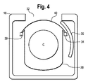
図3は、閉状態にある図1のメルター12の別の斜視図である。図3を参照すると、メルター12の装填室18は、選択的に開口22を横切って延びるドア30を有する。1つの実施形態において、ドア30は、開位置(図1)と閉位置(図3)との間で装填室18の内部に対して回転する回転ドアである。例えば、ドア30は、装填室18内に配置し(図4)、ドア30が開口22を横切って延びる閉位置への経路に沿って移動または摺動させることができる。この経路は、略弧状または円形とし、加熱素子24と装填室18の壁との間に延びることができる。
FIG. 3 is another perspective view of the
図4、5は、ドア30が開位置(図4)と閉位置(図5)との間で移動する装填室18の一例の上面図を示す略図である。図4、5を参照すると、1つの実施形態において、加熱バンド28は、容器「C」すなわちドラム缶を受容する受容位置と、加熱バンド28が容器「C」を実質的に囲む加熱位置との間で移動することができる。加熱バンド28は、開位置と閉位置との間でのドア30の移動とともに、受容位置と加熱位置との間で移動可能とすることができる。
4 and 5 are schematic diagrams illustrating a top view of an example of the
図4を参照すると、受容位置では、加熱バンド28は、容器「C」を装填室18の加熱バンド28の両側部間に受容することができるように、略「U字」状、または他の同様の形状に維持することができる。加熱バンド28は、加熱バンド28が容器「C」を完全にまたは実質的に囲むように略「O字」状に維持することができる図5に示す加熱位置に移動させることができる。すなわち、加熱位置では、加熱バンド28は、受容位置におけるのと比較して、加熱バンド28のより大きい表面積にわたって、容器「C」のより近位に配置される。
Referring to FIG. 4, in the receiving position, the
1つの実施形態において、各加熱バンド28の第1の端部32は、第1の支柱34に結合することができ、第1の端部32とは反対側の各加熱バンド38の第2の端部36は、第2の支柱38に結合することができる。第1の支柱34は、開位置(図1、4)から閉位置(図3、5)へのドア30の移動中、ドア30とともに移動可能とすることができる。第1の支柱34は、トラック40または同様のガイド機構に沿ってガイドすることができる。第2の支柱38は、実質的に静止状態に維持してもよいし、代替的には、トラック40に沿って第1の支柱34の方に移動させてもよい。1つの実施形態において、第1の支柱34は、第2の支柱38よりも長い移動経路を移動する。受容位置では、加熱バンド28の対向する自由端部、すなわち第1の端部32および第2の端部36は、第1の距離だけ離間し、加熱位置では、加熱バンドの対向する自由端部32、36は、他方に接触するか、第1の距離よりも短い第2の距離だけ離間する。
In one embodiment, the
動作時、1つの例によれば、第1の支柱34は、ドア30の経路と同様の経路に沿って移動することができる。ドア30の閉鎖中、第1の支柱34の移動により、加熱バンド28が受容位置から加熱位置の方に移動し、それにより、加熱バンドが、容器「C」を囲むかまたは実質的に囲むとともに容器「C」のより近位に配置されるように移動する。第2の支柱38は、第1の支柱34の方に移動し、加熱バンド28の張力を均一にするとともに、加熱バンド28内側の容器「C」を平衡およびセンタリングすることができる。ドア30と第1の支柱34および第2の支柱38のうちの少なくとも一方とは、ギアプレート(図示せず)によって駆動することができる。第1の支柱34および第2の支柱38は、サーボモーター(図示せず)によって更に制御することができる。
In operation, according to one example, the
図6〜図8は、必要に応じて第1の加熱素子28に取り付けることができる、引き込み保護スカート42を示している。例えば、第1の加熱素子28が1または複数の可撓性加熱バンド28として形成される上記実施形態では、保護スカート42を最下の加熱バンド28に取り付けて、受容位置と加熱位置との間での加熱バンド28の移動中の、最下の加熱バンド28と容器「C」のリム「R」との干渉を防止または制限することができる。
6-8 show a retractable
図6は、1つの実施形態に係る引き込み保護スカート42の背面図である。図7は、図6の引き込み保護スカート42の正面図である。この実施形態では、「背」面は、容器「C」に対面せず、加熱バンド28に固定される保護スカートの側面を指し、一方で、「正」面は、容器が装填室18に配置された場合、容器「C」に対面し、いくつかの構成において容器「C」に当接する側面を指すことが理解される。
FIG. 6 is a rear view of the
図6、7を参照すると、1つの実施形態に係る保護スカート42は本体44を備え、本体44は、第1の縁から延びる1または複数の固定アーム46と、第1の縁とは反対側の本体44の第2の縁から延びる1または複数のタブ48とを有する。本体44は、略円周方向にまたは加熱バンド28の長さと同じ方向に延びるように構成されている。固定アーム46は、略鉛直方向に、すなわち円周方向または長さ方向に対する横断方向に延びるように構成されている。1または複数のタブ48は、円周方向または長さ方向に対する略横断方向に延びるように構成されており、本体44に対して傾斜して、例えば略径方向に延びてもよい。
Referring to FIGS. 6 and 7, a
固定アーム46は、保護スカート42を加熱バンド28上に配置するように加熱バンド28に係合するように構成されている。1つの実施形態において、1または複数の固定アーム46は、保護スカート42を加熱バンド28上に保持することができるように、加熱バンド28の上縁の上方に延びる上部フック50と、加熱バンド28の下縁の下方に延びる下部フック52とを有する。一方で、いくつかの実施形態において、下部フック52が各固定アーム46に形成されない。例えば、本体44の両端部に配置された固定アーム46のところでは下部フック52を備えることができ、1または複数の中間固定アーム46のところでは下部フック52を省くことができる。
The fixed
保護スカート42は、加熱バンド28の後面または背面、すなわち容器「C」に対面しない側面にわたって、上部フック50と対向する下部フック52との間に延びる1または複数のジップタイ(図示せず)を含むこともできる。従って、保護スカート42は、意図せず取り外れないように加熱バンド28に取り付けることができる。1つの実施形態において、1または複数のジップタイは、メルター12の装填室18内の温度サイクルに耐えることが可能なステンレス鋼または同様の材料等の耐熱材料で作成することができる。
The
図8は、加熱バンド28および容器「C」に対する保護スカート42の一部を示す断面図である。図6〜図8を参照すると、保護スカート42の1または複数のタブ48は、本体44に対してゼロではない角度θで本体44の第2の縁から延びている。保護スカート42が、容器「C」の周囲の回りの加熱バンド28の略円形であるかまたは湾曲した外形に一致する一実施形態において、1または複数のタブ48は、円形であるかまたは湾曲した外形の径方向に少なくとも部分的に延びることができる。
FIG. 8 is a cross-sectional view showing a portion of the
好ましい一実施形態において、加熱バンド42に対面する側で本体44と1または複数のタブ48のそれぞれとの間に形成される角度θは、45度〜179度である。角度θは105度〜115度であることがより好ましいが、これに限定されない。
In a preferred embodiment, the angle θ formed between the
依然として図6〜図8を参照すると、1つの実施形態によれば、保護スカート42は使用時、単数または複数の上部フック50を加熱バンド28の上縁の上方に配置するとともに、単数または複数の下部フック52を加熱バンド28の下縁の下方に配置することにより、最下の加熱バンド28に取り付けることができる。図8に示すように、1または複数のタブ28は、後方に、すなわち容器「C」から離れる方向に角度θで傾斜している。容器「C」のリム「R」と容器「C」の本体との間に、間隙「G」が存在することができる。リム「R」に最も近い最下の加熱バンド28が、受容位置と加熱位置との間での移動中に弛む場合、1または複数のタブ48は、加熱バンド28と、リム「R」および容器「C」の本体間の間隙「G」との干渉を防止または制限することができる。例えば、保護スカート42は、加熱バンド28が容器「C」の間隙「G」に入るかまたは詰まるのを防止することができる。
Still referring to FIGS. 6-8, according to one embodiment, the
引き込み保護スカート42は、所望の用途に関して耐久性がある一方、開位置と閉位置との間での加熱バンド28の移動に対して柔軟であるとともに、保護スカート42を介しても加熱バンド28と容器「C」との間の十分な伝熱を依然として可能にするような厚さで形成することができる。すなわち、保護スカート42は、最下の加熱バンド28から容器「C」への伝熱に実質的に干渉しない伝熱特性を有する。従って、加熱バンド28は、保護スカート42が取り付けられているか否かに関わらず、おおよそ同じ温度まで加熱し、依然として容器「C」の十分な加熱および同様の性能結果をもたらすことができる。1つの実施形態において、保護スカート42は、厚さが約0.07インチ〜0.13インチ、より好ましくは約0.1インチとすることができる。一方で、本開示はこの構成またはこれらの寸法に限定されないことが理解される。
While the retractable
再び図1〜図3を参照すると、装填室18およびホッパー20は、互いに隣接して配置される。1つの実施形態において、装填室18およびホッパー20は、装填室18がホッパー20の上に位置するように、鉛直方向に互いに隣接して配置される。装填室18およびホッパー20は、開口部54を介して互いに流体連通する。装填室18およびホッパー20は、単一のユニットまたは互いに取り付けられる別個の複数のユニットとして形成することができる。開口部54は、例えば装填室18の底部またはホッパー20の頂部において、装填室18とホッパー20との間に配置されるプレートに形成することができる。
1-3 again, the
ホッパー20は、図1、3に概略的に示す第2の加熱素子55を備える。第2の加熱素子55は、例えば、1または複数の加熱されたプレート、バー、バッフル、または、ホットメルト接着剤を溶融させるとともに接着剤を溶融した流体状態に維持するのに十分な温度まで加熱されるホッパー20内の他の表面とすることができる。第2の加熱素子55は、例えば加熱マニホールドとして形成することができる。
The
動作時、1つの例によれば、容器「C」は、ドア30が開位置(図1、4)にある状態で、開口22を通して装填室18に装填することができる。容器「C」は、次に、第1の加熱素子28に対して配置することができる。第1の加熱素子28は、1または複数の加熱バンド28とすることができる。1つの実施形態において、容器「C」は、第1の加熱素子28が受容位置にある状態で、「U字」状の第1の加熱素子28の開き部を通して受け入れられる。ドア30は、閉位置(図3、5)に移動し、装填室18をカバー24のスロット26を除いて実質的に封鎖することができる。第1の支柱34および第2の支柱38は、加熱バンド28を、加熱バンド28が容器「C」の周囲の回りに実質的にまたは完全に延びる位置、すなわち加熱位置に移動させることができる。次に、加熱バンド28にエネルギー付与または加熱を行うことができ、ひいては、加熱バンド28からの熱が、容器「C」および容器「C」に収容されている接着剤スラグを加熱することができる。この熱は、接着剤の外側部分を溶融させ、接着剤スラグが容器「C」から開口部54を通してホッパー20内に落下することを可能にすることができる。次に、ホッパー20に収納されている接着剤スラグの固体部分をホッパー20内の第2の加熱素子55によって更に溶融し、流体状態に維持することができる。いくつかの実施形態において、接着剤スラグが容器「C」からホッパー20内に落下した場合を判定するセンサー(図示せず)をメルター12に配置することができる。
In operation, according to one example, container “C” can be loaded into
空の容器「C」は、装填室18から取り出し、接着剤スラグが収容されている別の容器「C」と交換することができる。従って、上記実施形態では、別の接着剤容器を装填室18に配置しながら、ホッパー20内で接着剤スラグを溶融することができる。接着剤スラグは、ホッパー20内の以前の容器「C」から供給された接着剤が尽きる前に、ホッパー20内に送出することができる。従って、ホッパー20内で連続供給される接着剤を維持し、続いて1または複数の計量ステーションおよび/または流体塗布装置(図示せず)に供給することができる。
The empty container “C” can be removed from the
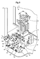
図9を参照すると、メルター12は、ポンプアセンブリ16を更に備えることができる。図9は、流体塗布装置のところまたは流体塗布装置の上流で、メルター12から流体塗布装置(図示せず)および/または計量ステーションに流体を供給するポンプアセンブリ16の一例の斜視図である。ポンプアセンブリ16は、流体供給装置10の一部および/またはメルター12の一部として実施することができる。代替的には、ポンプアセンブリ16は、メルター12とは別個に形成し、ホッパー20から溶融した接着剤を受け取るように、ホッパー20と流体連通状態に構成することができる。
Referring to FIG. 9, the
図9を参照すると、ポンプアセンブリ16はポンプ58を備える。1つの実施形態において、ポンプはピストンポンプである。一方で、ピストンポンプに加えてまたはピストンポンプの代わりに、限定はしないが例えばギヤポンプ等の他の好適なポンプを用いることもできることが理解される。ポンプアセンブリ16は、2つ以上のポンプ58を備えてもよいことも理解される。
Referring to FIG. 9, the
また、ポンプアセンブリ16は、フィルターアセンブリ60を備えることができる。フィルターアセンブリ60は、流体、例えばホットメルト接着剤の流路に配置し、経路を通って流れる流体を濾過することができる。フィルターアセンブリ60は、例えば1または複数の高容量フィルターを備えることができる。
The
また、ポンプアセンブリ16は、流体、すなわち溶融した接着剤をポンプアセンブリ16から1または複数の流体塗布装置(図示せず)および/または計量ステーション(図示せず)に送出または供給するための1または複数の送出ポート62を備えることができる。1つの実施形態において、各送出ポート62は、流体を異なる計量ステーションまたは流体塗布装置に送出することができる。すなわち、各送出ポート62は、異なる計量ステーションまたは流体塗布装置と連結することができる。例えば、図9に示す実施形態では、ポンプアセンブリ16は、4つの送出ポート62を備えることができる。ポンプアセンブリ16は、4つの異なる計量ステーションまたは流体塗布装置と流体接続することができ、各送出ポート62は、各ポートが流体接続されたそれぞれの計量ステーションまたは流体塗布装置に流体を送出することができる。
The
1または複数の送出ポート62は、ホース送出部とすることができる。ホース送出部62は、ポンプアセンブリ16から外方に突出することができ、流体を流体塗布装置に送るホースが取り付けられるように構成されている。本開示は4つの送出ポートに限定されないことと、ポンプアセンブリ16は必要に応じてより少数またはより多数の送出ポート62を備えてもよいこととが理解される。例えば、ポンプアセンブリは、個々の用途につき、所望されるのであれば、1つ〜10以上のいずれの数の送出ポート62を備えてもよい。さらに、各送出ポート62は、1または複数の流体塗布装置のところまたはその流体塗布装置の上流で、流体を1または複数の流体塗布装置および/または計量ステーションに送出することができることが理解される。
One or more delivery ports 62 may be a hose delivery section. The hose delivery section 62 can project outward from the
依然として図9を参照すると、ポンプアセンブリは、1または複数の圧力調節弁(PRV)64を更に備え、ポンプアセンブリ16から少なくとも1つの流体塗布装置または計量ステーションに送出される流体、すなわち溶融した接着剤の流れ、特に圧力を調節または制御することができる。1つの実施形態において、1または複数のPRV64のそれぞれは、それぞれの各送出ポート62の上流に配置される。一方で、他の実施形態において、PRV64は、それぞれの送出ポート62の下流に配置してもよいことが理解される。
Still referring to FIG. 9, the pump assembly further comprises one or more pressure regulating valves (PRV) 64, and the fluid delivered from the
1つの実施形態において、1または複数のPRV64は、個々の若しくは複数の流体塗布装置、計量ステーション、または計量アプリケーターに供給される流体の圧力を制御することができる。他の構成において、1または複数の計量ステーションまたは流体塗布装置への流れを制御するように、2つ以上のPRV64を設けることができる。すなわち、各PRV64は、それぞれの流体塗布装置または計量ステーションに連結することができ、いくつかの構成において、各流体塗布装置のところ若しくは各流体塗布装置の上流にある計量ステーションまたは計量アプリケーターと連結することができる。こうして、流体供給装置10は、複数の流体塗布装置および/または計量ステーションに、制御して送出される流体を供給することができ、各流体塗布装置および/または計量ステーションに供給される流体を、ポンプアセンブリ16のそれぞれのPRV64によって個々に計量または制御することができる。1つの例において、PRV64は、システムが、流体を1または複数の計量ステーションまたは流体塗布装置に供給するポンプ58を備える場合に用いられる。
In one embodiment, one or
1つの実施形態において、図9を更に参照すると、1または複数のPRV64は、第1のPRV64a、第2のPRV64b、第3のPRV64c、および第4のPRV64dを含むことができる。各PRV64a〜64dは、それぞれの送出ポート62a、62b、62c、62dに連結され、送出ポート62a、62b、62c、62dを通して、流体がそれぞれの計量ステーションおよび/または流体塗布装置に送出される。この例では、第1のPRV64aは、第1の送出ポート62aを通して第1の計量ステーションおよび/または流体塗布装置に送出される流体の流れ、例えば圧力を制御することができ、第2のPRV64bは、第2の送出ポート62bを通して第2の計量ステーションおよび/または流体塗布装置に送出される流体の流れを制御することができ、第3のPRV64cは、第3の送出ポート62cを通して第3の計量ステーションおよび/または流体塗布装置に送出される流体の流れを制御することができ、第4のPRV64dは、第4の送出ポート62dを通して第4の計量ステーションおよび/または流体塗布装置に送出される流体の流れを制御することができる。PRV64a〜64dは、それぞれの送出ポート62a〜62dを通して送出される流体の圧力を増減するかまたは流体の流れを停止することができる。
In one embodiment, with further reference to FIG. 9, the one or
また、ポンプアセンブリ16は、1または複数の圧力逃し弁66を含むことができる。圧力逃し弁66は、ポンプアセンブリ16内部から余剰な圧力を逃がすように機能することができる。
The
PRV64a〜64dおよび送出ポート62a〜62dは専ら例示の目的で記載されており、本発明はこの構成に限定されないことが理解される。例えば、追加のまたはより少数のPRV64および/または送出部62を設けてもよい。いくつかの実施形態において、ポンプアセンブリ16は、個々の計量ユニットへの圧力を制御するように単一のポンプを含むことができる。他の実施形態において、ポンプアセンブリ16は、アプリケーターまたは計量ユニットにそれぞれ独立して供給を行う複数のポンプを含むことができる。
It will be appreciated that PRVs 64a-64d and
さらに、他の実施形態において、PRV64を省くことができる。すなわち、いくつかの実施形態において、ポンプアセンブリ16の単数または複数のポンプ58は、1または複数の流体塗布装置のところまたはその流体塗布装置の上流で、1または複数の流体塗布装置または計量装置への流体の供給を直接制御してもよい。このように、ポンプ58を操作および制御して、流体供給装置10から流体を所望のように送出することを達成することができる。例えば、いくつかの実施形態において、単数または複数のポンプ58は、流体の圧力を調節するように制御することができる。
Further, in other embodiments,
このように、上記実施形態では、ポンプアセンブリ16は、流体、すなわち溶融した接着剤をホッパー20から1または複数の計量ステーション、計量アプリケーター、および/または流体塗布装置に供給することができる。いくつかの構成において、1または複数の計量ステーションまたは計量アプリケーターは、それぞれの流体塗布装置のところまたはその流体塗布装置の上流に配置することができる。ポンプアセンブリ16はポンプ58を含む。ポンプ58は、ピストンポンプまたはギヤポンプとすることができる。ポンプ58は、1または複数の送出ポート62を通して流体を送出するように構成されており、各送出ポート62は、流体をそれぞれの計量ステーション、計量アプリケーター、または流体塗布装置に供給するように構成されている。ポンプアセンブリ16は、1または複数のPRV64を含むことができる。各PRV64は、送出ポート62から送出される流体の圧力を制御するように、それぞれの送出ポート62に対して配置することができる。従って、1または複数の計量ステーション、計量アプリケーター、または流体塗布装置に送出される流体の圧力は、それぞれの送出ポート62でPRV64によって個々に独立して制御することができる。そのため、流体は、それぞれの計量ステーション、計量アプリケーター、または流体塗布装置に供給される流体の圧力を制御するPRV62の動作に基づき、各計量ステーション、計量塗布装置、または流体塗布装置ごとに独立して個々に制御された圧力で、異なる計量ステーション、計量アプリケーター、または流体塗布装置に同時に供給することができる。
Thus, in the above embodiment, the
代替的には、1または複数のPRV64は省くことができ、ポンプアセンブリ16は、1または複数のポンプ58を含むことができる。各ポンプ58は、1または複数の送出ポート62を通して流体を送出することができる。各送出ポート62は、流体をそれぞれの計量ステーション、計量アプリケーター、または流体塗布装置に供給するように構成されている。各ポンプ58は、独立して個々に制御して、独立して個々に制御された圧力で、流体をそれぞれのポンプ58と流体接続された1または複数の送出ポート62に送出することができる。従って、流体は、計量ステーション、計量アプリケーター、または流体塗布装置と流体連通するそれぞれのポンプ58の独立した個々の動作に基づき、独立して個々に制御された圧力で、1または複数の計量ステーション、計量アプリケーター、または流体塗布装置に同時に供給することができる。上記実施形態では、PRV64またはポンプ58は、計量ステーション、計量アプリケーター、または流体塗布装置への流体の流れを停止するように動作することができることが更に理解される。ポンプアセンブリ16は、必要に応じて、例えば1つ〜20以上の計量ステーション、計量アプリケーター、または流体塗布装置に流体を供給することができる。各計量ステーション、計量アプリケーター、または流体塗布装置は、流体供給装置10に対して遠隔に配置することができる。
Alternatively, one or
流体供給装置10は、制御装置68を更に備えることができる。制御装置68は、他の要素の中でも、PRV64を制御するようにPRV64に作用可能かつ通信可能に接続することができる。制御装置68は、例えば、外部装置に対してデータを送受信する入出力(I/O)ユニット、データを記憶するメモリユニット、受信ユニット、および送信ユニットを備えることができる。上述の制御装置68の種々の機能部は、互いに作用可能かつ通信可能に接続されることが理解される。これらの装置は、制御装置68の一部として記載されているが、制御装置68とは別個とし、制御装置68に作用可能かつ通信可能に接続することができることが更に理解される。
The
制御装置68は、限定はしないがメモリユニット等の1または複数のコンピューター可読記憶媒体に記憶されたプログラム命令を実行する、マイクロプロセッサまたはマイクロプロセッサを有するコンピューターとして実施することができる。コンピューター可読記憶媒体は、非一時的媒体、例えばハードディスクおよびフロッピーディスクを含む磁気媒体、CD−ROMディスクおよびDVDおよび/または光学ディスクを含む光学媒体を含む。コンピューター可読記憶媒体は、読出し専用メモリ(ROM)、ランダムアクセスメモリ(RAM)、フラッシュメモリ等を含む、プログラム命令を記憶および/または実行するハードウェア装置を含むこともできる。非一時的媒体は、信号または電波を含まないことが理解される。
The
1つの実施形態において、制御装置68は、1または複数のPRV64に作用可能かつ通信可能に接続することができる。制御装置68は、各PRV64を独立して制御するように構成することができる。例えば、図9に示す構成を参照すると、制御装置68は、各PRV64a〜64dを個々に互いに独立して制御することができる。従って、PRV64a〜64dおよびそれぞれの送出部62a〜62dを通ってそれぞれの流体塗布装置および/または計量ステーションに流れる流体の圧力は、変化する流体の圧力に基づき、単一の供給源すなわち流体供給装置10から供給される流体を受け取りながら、流体供給装置を異なる用途に用いることができるように制御することができる。すなわち、それぞれの流体塗布装置に送出される流体の圧力は、異なる流体塗布装置または計量ステーションが個々に調整された圧力で流体を受け取るように、独立して個々に制御することができる。1つの例において、流体は、制御装置68によるPRV64a〜64dの制御に基づき、異なるように調整された圧力で、各流体塗布装置または計量ステーションに送出することができる。一方で、流体の所望の圧力は、PRV64a〜64dのうちのいくつかまたは全てにわたって同じとしてもよく、上記例に限定されないことが理解される。流体の圧力を所定の地点で測定または検出するように、複数のセンサー(図示せず)を備えてもよい。センサーは、制御装置68と通信することができ、さらに、制御装置68は、センサーから受信した測定データまたは検出データに基づきまたはこのデータに応じて、1または複数のPRVを操作または制御することができる。
In one embodiment, the
図10は、1つの実施形態に係る流体供給装置10および容器ハンドリングシステム14の斜視図である。図10を参照すると、容器ハンドリングシステム14は、メルター12に対して遠隔に配置された、容器「C」を最初に配置する装填プラットフォーム70を必要に応じて備えることができる。装填プラットフォーム70は、容器「C」と接触する表面積を減少するために、例えば、スロット、溝、および/またはバッフルを伴って形成することができる。装填プラットフォーム70は、ポリテトラフルオロエチレン(PTFE)等の低摩擦材料若しくは非粘着性材料、または他の同様の材料から作成することもできる。装填プラットフォーム70は、容器「C」がその上で位置決めされる位置決め特徴部を有することができる。例えば、装填プラットフォーム70は、容器「C」の直径に対応する略円筒形の内部に容器「C」を受ける凹部を有することができる。代替的にまたは加えて、装填プラットフォーム70は、1または複数の直立した確実な停止部を有することができる。直立した停止部は、容器「C」を装填プラットフォーム70上の適切な位置にガイドするように、略「V字」形状に構成することができる。
FIG. 10 is a perspective view of the
1つの実施形態において、容器ハンドリングシステム14は、メルター12に対して遠隔の、例えば装填プラットフォーム70上方の第1の位置から、メルター12上方の第2の位置まで延びるレール72も備える。トロリー74が、レール72上で摺動可能または転動可能に配置され、レール72に沿って第1の位置から第2の位置に移動するように構成されている。トロリー74は、例えばチャック76を用いて容器「C」に解除可能に取り付け可能である。レール72は、その両端に確実な停止部72a、72bを有することができる。
In one embodiment, the container handling system 14 also includes a rail 72 that is remote from the
容器ハンドリングシステム14は、支持構造体78を備えることもできる。支持構造体78は、レール72に直接的または間接的に取り付けられた1または複数の支持ブラケットを含むことができる。支持構造体78は、装填プラットフォーム70に固定され、装填プラットフォーム70を支持することもできる。
The container handling system 14 can also include a
レール72は、第1の位置と第2の位置との間の傾斜セグメントを有することができる。トロリー74は、レール72に沿って傾斜セグメントを登り、メルター12上方の第2の位置に移動するように構成されている。トロリー74には、例えば、モーター(図示せず)または外部駆動機構によって動力供給することができる。トロリー74をレール72に沿って駆動するのに、他の同様の好適な装置を用いることができる。従って、チャック76が容器「C」に取り付けられると、レール72に沿ったトロリー74の移動により、容器が装填プラットフォーム70から上昇位置まで持ち上げられ、装填室18の開口22を通して装填室の内部に受け入れられる。トロリー74またはチャック76の一部が、装填室18のカバー24に形成されたスロット26を通って延びてもよい。容器「C」は、トロリー72を反対方向に、すなわち第1の位置の方に駆動し、開口22を通して容器「C」を外方に移動させ、容器「C」を装填プラットフォーム70に戻すことにより、メルター12から取り外すことができる。
The rail 72 can have an inclined segment between a first position and a second position. The trolley 74 is configured to climb the inclined segment along the rail 72 and move to a second position above the
図11は、本明細書に記載の別の実施形態に係る容器ハンドリングシステム114の斜視図である。容器ハンドリングシステム114は、容器「C」に解除可能に係合し、容器「C」を第1の方向「D1」に、メルター12の装填室18内への装填に好適な所定の高さまで持ち上げ、容器「C」を第2の方向「D2」に、メルター12に対して遠隔の位置からメルター12の装填室18内部の位置まで移動させるように構成されている。
FIG. 11 is a perspective view of a
図11を参照すると、1つの実施形態において、容器ハンドリングシステム114は、メルター12に対して遠隔の第1の位置からメルター12上方の第2の位置まで延びるレール116を備える。1つの例において、レール116は、略一様な水平方向に延びることができる。レール116は、支持構造体118によって支持することができる。1つの実施形態において、支持構造体は、メルター12に据え付けられる。別の実施形態において、支持構造体118は自己支持型であり、メルター12とは別個とすることができる。すなわち、支持構造体118は、いくつかの実施形態において、メルター12から独立することができる。
Referring to FIG. 11, in one embodiment, the
レール116にはトロリー120が結合され、トロリー120は、レール116に沿って摺動または転動して、容器「C」をメルター12に対して遠隔の位置から装填室18内部の位置に移動させるように構成されている。トロリー120は、レール116に沿ってモーターで駆動および/または手動で駆動することができる。モーターは、トロリー120のところに配置することができ、トロリーとともに移動可能とすることができる。代替的には、モーターは、トロリー120とは遠隔に配置し、チェーン駆動機構等、モーターからトロリー120に動力を送出する既知の機構を用いて、トロリー120をレール116に沿って駆動するように構成することができる。種々の構成部品を収容するように、レール116に沿ってベローズを配置することができる。
A
容器ハンドリングシステム114は、リフト機構122を更に備える。リフト機構は、容器「C」を第1の方向に、例えば鉛直方向に、容器「C」をメルター12の装填室18内に配置することができる高さまで持ち上げるように構成されている。1つの実施形態において、リフト機構122は、電気ホイスト、ウィンチ、または同様の機構として実施することができる。例えば、ホイストは、トロリー120に連結するかまたはトロリー120と一体に形成することができる。例えば、トロリー120およびリフト機構122は、モーターとトロリー120とホイスト122とがレール116に沿って移動する1つのユニットとして実施される、モーター付電気ホイストとして実施することができる。以下で更に記載するように、ケーブルまたはチェーン等の柔軟な部材124をホイストから伸縮可能に延ばし、容器「C」に連結することができる。
The
図11を更に参照すると、容器ハンドリングシステム114は、安定化リンク機構126を更に備えることができる。図12は、本明細書に記載の一実施形態に係る安定化リンク機構126の側面図である。図11、12を参照すると、安定化リンク機構126は、トロリー120に連結する第1の端部と、容器「C」に結合する第2の端部とを有する。1つの実施形態において、安定化リンク機構126は、容器「C」が昇降される方向に伸縮可能とすることができるシザー型リンク機構128であるを含む。一方で、安定化リンク機構126はこの例に限定されず、例えば、1または複数の伸縮ロッド、伸縮プレート、または伸縮ブラケットとすることができることが理解される。
Still referring to FIG. 11, the
安定化リンク機構126は、第1の連結ピース130を介してトロリー120に連結することができる。第1の連結ピース130は、例えばボルトまたは同様の既知の締結装置を用いて、一方の端部がシザー型リンク機構128に固定され、もう一方の端部がトロリー120に結合されるコネクタブロックとして形成することができる。コネクタブロック130は、例えば、ねじりに耐えるとともに安定化リンク機構126に沿って伝達される軸方向の力を減少させるようにねじり力および軸方向の力を吸収する衝撃吸収特性を有する、ゴムを含むエラストマー材料または同様の弾性材料で作成することができる。
The stabilizing
再び図11を参照すると、安定化リンク機構126は、第1の連結ピース130とは反対側のもう一方の端部に、安定化リンク機構をチャック134に連結する第2の連結ピース132を備えることができる。図13は、第2の連結ピース132を介してチャック134に連結された安定化リンク機構126の一部を示す斜視図である。
Referring again to FIG. 11, the
図11〜図13を参照すると、1つの実施形態において、第2の連結ピース132は、2つの軸の回りでの回動自由度を所定の範囲で可能にするように構成されている。このために、1つの実施形態において、第2の連結ピース132は、L字状ブラケット136およびL字状プレート138を含む。L字状ブラケット136は、シザー型リンク機構128に取り付けられており、第1の軸「A1」上でシザー型リンク機構136に対して回動可能とすることができる。1つの実施形態において、第1の軸「A1」は、L字状ブラケット136をシザー型リンク機構128に取り付ける締結具を通って延びる。L字状プレート138は、L字状ブラケット136に取り付けられており、第2の軸「A2」上でL字状ブラケット136に対して回動可能とすることができる。1つの実施形態において、第2の軸「A2」は、L字状プレート138をL字状ブラケット136に取り付ける締結具を通って延びる。
Referring to FIGS. 11 to 13, in one embodiment, the second connecting
第1の軸「A1」および第2の軸「A2」は、互いに交差するように延びる。第2の連結ピース132における接続部に柔軟性を与える(さもなければこの接続部は剛直である)ように、第1の軸「A1」および第2の軸「A2」の回りに回動自由度がもたらされる。従って、第1の軸「A1」および第2の軸「A2」の回りでの回動によって、第2の連結ピースに印加または伝達される外力を少なくとも部分的に吸収することができる。すなわち、安定化リンク機構126は、剛直な構成に対して耐久性を増すように、例えば第2の連結ピース132における種々の構成部品の撓みによって、いくらかの外力を吸収することができる。
The first axis “A1” and the second axis “A2” extend so as to cross each other. Freely pivotable about the first axis “A1” and the second axis “A2” to provide flexibility to the connection in the second coupling piece 132 (otherwise the connection is rigid) Degrees are brought. Therefore, the external force applied or transmitted to the second connecting piece can be absorbed at least partially by the rotation around the first axis “A1” and the second axis “A2”. In other words, the stabilizing
図13を更に参照すると、L字状プレート138は、チャック134に取り付けることができる。1つの実施形態において、L字状プレート138は、チャック134に連結する第1の締結具(図示せず)を受ける締結穴140を有する。L字状プレート138は、同様にチャック134に結合される第2の締結具(図示せず)を受ける弧状のスロット142を更に有することができる。使用時、1つの例によれば、弧状のスロット142は、容器「C」に対してチャック134を調整および位置決めするために、締結穴140を通って延びる第3の軸「A3」の回りでの、L字状プレート138に対するチャック134の回動またはチャック134に対するL字状プレート138の回動を可能にする。第3の軸「A3」の回りでの回動は、弧状のスロット142の長さに対応する許容可能な所定の程度に制限される。
Still referring to FIG. 13, the L-shaped
図14は、内側に容器「C」を保持しているチャック134の正面斜視図である。図15〜図17は、安定化リンク機構126およびリフト機構122に異なる構成で取り付けられるチャック134の斜視図である。図13〜図17を参照すると、1つの実施形態において、チャック134は、容器「C」の回りに取り付けられ、容器「C」に締め付け力を印加する締め付けバンド144を備える。1つの実施形態において、締め付けバンド144は、ガイドバンド146と、第1のアーム148と、第2のアーム150とを含む。チャック134は、締め付けバンド144に結合される1対のブレース154と、ブレース154間に延びる横バー156とを有する支持ブラケット152を更に含む。第1のアーム148および第2のアーム150は、それぞれのブレース154またはガイドバンド146に回動可能に取り付けられている。第1のアーム148および第2のアーム150は、それぞれの磁気ラッチ(図示せず)を用いて開位置に維持することができる。1つの実施形態において、横バー156上に、リフト機構122と連結するラグ157を形成することができる。例えば、柔軟な部材124は、その遠位端部にラグ157と連結するフックまたはラッチを有することができる。代替的には、柔軟な部材124は、ボルトを用いて横バー156に取り付けることができる。他の既知の連結機構を用いることもできる。
FIG. 14 is a front perspective view of the
リンケージブラケット158およびリンケージカウンターウェイト160が、横バー156上に配置されるとともに横バー156に取り付けられる。リンケージブラケット276は、第2の連結ピース132のL字状プレート138に取り付けられ、それにより安定化リンク機構126をチャック134に取り付けるように構成されている。1つの実施形態において、リンケージブラケット158およびリンケージカウンターウェイト160は、横バー156に回動可能に取り付けられており、チャック134が図15〜図17に示す第1の構成、第2の構成、および第3の構成の間で回動される場合、メルター12に対する固定位置を維持する。代替的には、リンケージブラケット158およびリンケージカウンターウェイトは、例えば対応する締結穴に受けられるねじまたはボルトを用いて横バー156に選択的に取り付け可能であり、横バー156上で再配置可能である。リンケージブラケット158およびカウンターウェイト160は、横バー156に沿ってまたは横バー156を横断する方向に位置合わせすることが必ずしも必要でないことが理解される。すなわち、リンケージブラケット158およびカウンターウェイト160は、横バー156に沿って互いからオフセットすることができる。1つの例において、リンケージブラケット158は、例えば図16に示すように、横バー156に対して横断方向に延びるように配置してもよい。一方で、カウンターウェイト160は、カウンターウェイト160がリンケージブラケット158からオフセットするように、横バー156の長さに沿って異なる場所、すなわち図16に示す位置とは異なる場所に配置してもよい。カウンターウェイト160は、カウンターウェイト160および横バー156に形成された対応する締結穴を通って延びるボルトまたはねじ等の好適な締結具を用いて、横バー156に取り付けることができる。
The
図13〜図17、特に図14を更に参照すると、チャック134は、容器「C」に締め付け力を選択的に印加し、内側に容器「C」を固定するように構成されている。このために、チャック134は、締め付け機構162を更に備えてもよい。締め付け機構162は、第1のアーム148および第2のアーム150に力を印加するかまたはこの力を解除するように構成され、第1のアーム148および第2のアーム150が容器「C」に締め付け力を印加するかまたはこの力を解除することができるようになっている。締め付け機構162は、第1のアーム148および第2のアーム150のうちの一方に枢動可能に取り付けられたハンドル164と、ハンドル164に偏心して枢動可能に取り付けられたラッチ166と、第1のアーム148および第2のアーム150のうちの他方に取り付けられた留め具168とを備える。使用時、ラッチ166は、枢動して留め具168に係合することができる。ハンドル164は、第1のアーム148および第2のアーム158を互いに向かって引き寄せる力をラッチ166が留め具168に印加し、それにより容器「C」に締め付け力を印加するように、回動することができる。ハンドル164は、締め付け位置では、ピン170がブラケット172を貫通した状態で適所に固定することができる。
With further reference to FIGS. 13-17, and in particular, FIG. 14, the
締め付け機構162は、第1のアーム148と第2のアーム150との間に延びる確実な停止部174を更に有することができる。確実な停止部174は、第1のアーム148および第2のアーム150のうちの一方に取り付けられ、締め付け中(すなわちハンドル164を回動させて、ラッチ166を介して留め具168に力を印加する間)、第1のアーム148および第2のアーム150のうちの他方にあるフランジと接触させることができる。従って、確実な停止部174は、容器「C」に印加される締め付け力を制限することができる。
The
図14を更に参照すると、流体供給装置10は、内側に容器「C」を固定することができる位置にチャック134をガイドおよび保持するクレードル176も備えることができる。1つの実施形態において、クレードル176は、基部178と、基部178から延びるガイド部180とを有する。1つの実施形態において、ガイド部180は、容器「C」を受ける略U字状部として形成される。ガイド部180は、ガイド部180から延びる複数の傾斜したタブ182を有することができる。複数の傾斜したタブ182は、チャック134を受けて、チャック134が容器「C」に固定され得る位置にチャック134をガイドするように構成されている。
Still referring to FIG. 14, the
容器ハンドリングシステムは、上述の実施形態に限定されないことが理解される。例えば、別の実施形態において、容器ハンドリングシステムは、容器「C」に取り付けられるチャック(図示せず)の各側に取り付けられ、ともに連結される、油圧式平行リンク機構(図示せず)として実施することができる。油圧式平行リンク機構は、例えば、メルター12の両側に枢動可能または回動可能に取り付けられた1つの更なるリンケージアーム(図示せず)を含むリンケージアセンブリ(図示せず)と、両側のそれぞれがリンケージアセンブリに枢動可能または回動可能に取り付けられた油圧式ラム(図示せず)とを備えることができる。油圧式ラムは、リンケージアセンブリを駆動して、容器「C」をチャック内に配置および固定することができる下降位置と、容器「C」が持ち上げられて装填室18内に移動される上昇位置との間で移動させるように構成されている。油圧式ラムは、リンケージアセンブリのピボット軸または回転軸から離間した位置でリンケージアセンブリに結合することができ、それにより、油圧式ラムは、リンケージアセンブリを下降位置から上昇位置に回動するように駆動することができる。油圧式ラムは、ピストンに印加される油圧荷重またはピストンから除去される油圧荷重に応じてピストンがシリンダーに対して後退位置と延出位置との間で摺動可能である、ピストンシリンダー形態(図示せず)で形成することができる。1つの実施形態において、リンケージアセンブリは、下降位置から上昇位置への移動および上昇位置から下降位置への移動の際、略90度回転される。
It will be appreciated that the container handling system is not limited to the embodiments described above. For example, in another embodiment, the container handling system is implemented as a hydraulic parallel linkage mechanism (not shown) that is attached to and coupled together on each side of a chuck (not shown) attached to the container “C”. can do. The hydraulic parallel linkage mechanism includes, for example, a linkage assembly (not shown) including one additional linkage arm (not shown) pivotally or pivotally attached to both sides of the
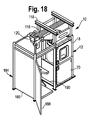
図18〜図20を参照すると、流体供給装置10は、アクセス領域184を更に有することができる。1つの実施形態において、アクセス領域184は、メルター12の開口22が形成された側に隣接する領域を実質的に囲む周辺部を有する。従って、アクセス領域184は、メルター12とともに、容器「C」がチャック134内に固定されるとともに装填室18内に移送される装填領域を略囲むことができる。すなわち、1つの実施形態において、アクセス領域184は、メルター12の少なくとも1つの側面とともに、容器「C」をチャック134によって固定するとともに装填室18内に移動することができる領域を有する。装填プラットフォーム70は、アクセス領域184内に封鎖することができる。
With reference to FIGS. 18-20, the
1つの実施形態において、アクセス領域184は3つの側面を有して形成され、メルター12の側面に対して配置された場合、アクセス領域184とメルター12とが略正方形または矩形の領域を形成するようになっている。一方で、本開示はこの構成に限定されないことが理解される。例えば、アクセス領域184は、別の多角形、または代替的には円形若しくは楕円形の領域を形成するようにしてもよい。いくつかの実施形態において、アクセス領域184は4つの側面を有して形成することができ、ここでは、容器「C」が装填室18に対して出入りすることを可能にするように、1つの側面がメルター12の開口22に対応する開口を有する。他の実施形態において、開口側面を有するアクセス領域184が形成され、メルター12は、メルター12の開口22がアクセス領域184によって形成される領域に対面する状態で、上記開口側面に配置することができる。
In one embodiment, the
アクセス領域184は1または複数のパネル186を備えることができる。1つの実施形態において、アクセス領域184は複数のパネル186を備える。1つのパネル186をドア188として形成してもよいし、代替的には、アクセス領域184の内部へのユーザーアクセスを可能にするアクセス部190を形成するように、1つのパネル186を省いてもよい。使用時、アクセス部190は、使用者または作業者が容器「C」をアクセス領域184内に配置し、容器「C」をチャック134内に固定することを可能にすることができる。従って、チャック134のハンドル164は、アクセス部190と概ね位置合わせされるとともにアクセス部190の最近傍にあり、作業者がハンドル164を操作してチャック134を動作させることができるようになっている。
アクセス領域184は、1または複数のパネル186およびドア188を固定することができる枠組192を更に備えることができる。枠組192は、メルター12に固定することができる。代替的には、枠組192は、自己支持型とすることができる。一方で、枠組192は必ずしも必要ではなく、1または複数のパネル186およびドア188は互いに固定し、自己支持型とすることができることが理解される。
1つの実施形態において、アクセス領域184は再構成可能であり、そのため、ドア188および/またはアクセス部190の場所はメルター12に対して移動させることができる。従って、各パネル186およびドア188は、枠組192、隣接するパネル186、またはメルター12に解除可能に取り付けることができる。
In one embodiment, the
別の実施形態において、アクセス領域184は、枠組の両側に回動可能に取り付けられた、2つの観音開きドア(図示せず)によって形成することができる。1つの例において、各観音開きドアは、第1の脚と、第1の脚に対して傾斜した第2の脚とを有して形成することができる。閉位置では、各ドアの第1の脚は、装填領域の両側で装填領域へのアクセスを制限し、一方で、第2の脚はともに、メルター12に対面する装填領域の正面側へのアクセスを制限する。こうして、この構成では、上記2つの観音開きドアは、略正方形または矩形の領域の3つの側の回りでのアクセスを制限することができる。第4の側は、メルター12に対して開放することができる。さらに、アクセス部190は、メルター12と装填領域との間の第4の側に形成することができる。すなわち、装填プラットフォーム70を含む装填領域は、メルター12から十分に離隔し、メルター12と装填領域との間で作業者がチャック134を操作および/または制御パネル(図示せず)を操作することを可能にすることができる。別のドア(図示せず)がメルター12と観音開きドアとの間に配置され、装填領域とメルター12との間の空間およびアクセス部190へのアクセスを制限することができる。観音開きドアは、開位置では、装填領域の3つの側へのアクセスを可能にする。代替的には、観音開きドアは、形状が湾曲するかまたは部分的に円形とすることができる。
In another embodiment, the
1つの例において、図18に示すように、複数の構成のうちの右側構成を挙げることができ、ここでは、メルター12の開口22に向かって見た場合、ドア188およびアクセス部190は右側に配置されている。代替的には、図19に示すように、アクセス領域184は正面構成で形成してもよく、ここでは、メルター12に向かって見た場合、ドア188およびアクセス部190は開口22の正面に配置される。また、図20に示すように、アクセス領域184は左側構成で形成してもよく、ここでは、メルター12の開口22に向かって見た場合、ドア188およびアクセス部190は左側に配置される。
In one example, as shown in FIG. 18, a right side configuration among a plurality of configurations can be cited, where the
図15〜図17および図18〜図20を参照すると、チャック134は、第1の構成と、第2の構成と、第3の構成との間で移動させ、アクセス領域184の構成に対応させる、特にアクセス領域184のドア188および/またはアクセス部190の位置に対応させることができ、それにより、ハンドル164はドア188またはアクセス部190の最近傍に配置され、第1のアーム148および第2のアーム150が、ドア188またはアクセス部190の位置に対応する方向から容器「C」を間に受容するように開く。例えば、図18に示すように、アクセス領域184の右側構成では、チャック134は、図15に示すように第1の構成であることができる。図19に示すアクセス領域184の正面構成では、チャック134は、略90度回転させ、図16に示す第2の構成にすることができる。さらに、図20に示すアクセス領域184の左側構成では、チャック134は、おおよそ更に90度(図15の第1の構成から180度)回転させ、図17に示す第3の構成にすることができる。
Referring to FIGS. 15-17 and 18-20, the
上述の構成は単に例示のためのものであり、本開示は上記構成に限定されないことが理解される。例えば、チャック134は90度ではない間隔で回転させ、異なる構成間で移動させることができ、リンケージブラケット158およびリンケージカウンターウェイト160は、横バー156に対して、図に示す位置合わせされた垂直位置ではない位置に配置または固定することができる。
It will be understood that the above-described configurations are merely exemplary and the present disclosure is not limited to the above-described configurations. For example, the
アクセス領域184は、アクセス領域184内の容器「C」の装填および移送領域を、流体供給装置10が使用される施設の隣接する部分から仕切るように用いることができる。従って、装填室18への容器「C」の装填および装填室18からの容器「C」の除去は、施設内の他の移動物体からの不慮の干渉または施設内の他の移動物体との不慮の干渉を回避することができる、略仕切られた領域において行うことができる。
例えば、容器「C」の位置、ホッパー20内の接着剤の液面高さ、接着剤スラグが容器「C」からホッパー20内に落下したかどうか、チャック134から容器「C」に印加される締め付け力、ハンドル164が締め付け位置にしっかり係止されているかどうかを測定するように、複数のセンサーを流体供給装置10全体にわたって配置することができる。センサーは、種々の他の状態も測定、検出、または記録することができる。センサーは、制御装置68と通信可能に接続することができ、さらに、制御装置68は、流体供給装置10の種々の機能部、例えば、リフト機構122、容器ハンドリングシステム14、114、ドア30、加熱素子28および/またはポンプシステム16、並びに流体供給装置10の個々の構成要素を含む機能部と通信可能かつ作用可能に接続されている。従って、容器「C」がチャック134に装填および固定されると、容器「C」は、装填室18内に自律的に装填、および空になった場合は除去することができる。1つの実施形態において、流体供給装置10は、このような通信に対応するためのケーブルまたは配線を収容するように、例えばケーブル保持器194(図11を参照)を備えることができる。
For example, the position of the container “C”, the liquid level height of the adhesive in the
動作時、上記実施形態によれば、アクセス部190および/またはドア188を通して、満タンの容器「C」をアクセス領域184内に受容することができる。作業者は、締め付け機構162を操作することにより、容器「C」をチャック134内に固定することができる。リフト機構122、例えばホイストは、柔軟な部材124の遠位端部をラグ157に連結することにより、チャック134に取り付けることができる。安定化リンク機構126の第2の連結ピース132も、チャック134に連結される。
In operation, according to the above embodiment, a full container “C” can be received in the
アクセス領域184のドア188は閉鎖することができ、リフト機構122を操作して、容器「C」をメルター12の装填室18内への装填に十分な所定の高さまで持ち上げることができる。安定化リンク機構126、すなわちシザー型リンク機構128は、容器「C」を持ち上げるのにつれて伸張状態から収縮位置に動かすことができる。安定化リンク機構126は、容器「C」の捻回、揺動、若しくは回転を防止または制限することにより、容器「C」が持ち上げられる際に容器「C」を安定化するように構成されている。容器「C」が所定の高さまで持ち上げられる間またはその後のいずれかにおいて、トロリー120を例えばモーターによって駆動してレール116に沿って移動させ、容器「C」をメルター12に向かって開口22を通して装填室18内に移送することができる。
The
容器「C」を装填室18内に配置すると、ドア30を、開口22を横切る閉位置に移動させることができる。容器「C」は、カバー24のスロット26を通って延びるチャック134およびリフトシステム122によって鉛直方向に保持される。ドア30が閉位置に移動することにより、第1の加熱素子28が受容位置(図4)から加熱位置(図5)に移動する。加熱素子28が受容位置から加熱位置に移動することにより、容器「C」に回転力を与えることができる。この回転力は、チャック134を介して第1の連結ピース130、第2の連結ピース132、および安定化リンク機構126に伝達することができる。エラストマー材料のブロックを含み得る第1の連結ピース130は、回転力に応じて捻回し、回転力を吸収するように回転力を吸収することができる。次に、第1の加熱素子28、例えば1または複数の加熱バンドにエネルギー付与または加熱を行い、容器「C」および容器「C」内に保持されている接着剤スラグに熱を伝えることができる。加熱素子28から伝達される熱により、接着剤の外側部分が溶融し、スラグ接着剤が容器「C」から開口部54を通してホッパー20内に落下することが可能になる。
When container “C” is placed in
接着剤スラグは、ホッパー20内で第2の加熱素子55によって引き続き加熱され、流体になる。ポンプアセンブリ16を操作して、1または複数の送出ポート62を通して1または複数の計量ステーション(図示せず)または流体塗布装置(図示せず)に流体を圧送する。1または複数の送出ポート62を通して送出される流体の圧力は、各送出ポート62と連結される1または複数のPRV64によって制御することができる。
The adhesive slag is subsequently heated by the
容器「C」の内容物(すなわち接着剤スラグ)が空になった後、ドア30を開放することができ、第1の加熱素子28を加熱位置から受容位置に移動させることができる。次に、トロリー120をレール116に沿って駆動し、開口22を通して装填室18から容器「C」を取り出すことができる。好適な距離だけメルター12から離れると、リフト機構122を操作して、容器「C」を下降させることができ、安定化リンク機構126、特にシザー型リンク機構128を伸張することができる。作業者は、ドア188を開放するかまたはアクセス部を通してチャック134にアクセスし、締め付け機構162を操作して容器「C」にかかる締め付け力を解除し、チャック134から容器「C」を除去することができる。次に、接着剤スラグが収容されている新しい容器「C」をチャック134内に配置および固定することができる。
After the contents of container “C” (ie, the adhesive slag) are emptied, the
上記実施形態では、ホッパー20内に供給された接着剤を維持しながら、空の容器「C」を除去して新しい容器「C」容器と交換することができる。新しい容器を加熱することができ、ホッパー20内の供給された接着剤が尽きる前に、更なる接着剤をホッパー20に加えることができる。従って、ホッパー20内には、1つ若しくは計量ステーションおよび/または1または複数の流体塗布装置に供給されるように一定供給される接着剤を準備することができる。容器「C」は、メルター12のホッパーから計量ステーションまたは流体塗布装置への流体の供給を停止することなく取り替えおよび交換することができる。
In the above embodiment, the empty container “C” can be removed and replaced with a new container “C” while maintaining the adhesive supplied in the
図21は、1つの実施形態に係る本明細書に記載の流体供給装置を動作させる方法を示す図である。本方法は、全体としてS200で示されている。本方法は、S210において、リフト機構122を用いて容器「C」を開口22に対応する所定の高さまで持ち上げることを含む。S212において、トロリー120によって、容器「C」をメルター12に対して遠隔の位置から開口22を通して装填室18内部に移送する。S214において、ドア30を開位置から閉位置に移動させ、S216において、1または複数の第1の加熱素子28を受容位置から加熱位置に移動させる。S218において、加熱素子28にエネルギー付与して容器「C」および容器「C」の内容物を加熱する。内容物はホットメルト接着剤とすることができる。引き続き加熱しながら、S220において示すように、容器「C」の内容物をホッパー20に受け取る。S222において、ホッパー20は、第2の加熱素子55を用いて内容物(例えばホットメルト接着剤)を引き続き溶融する。S224において、ポンプアセンブリ16は、その溶融した接着剤を1または複数の計量ステーションおよび/または1つの更なる流体塗布装置に送出する。いくつかの実施形態において、ポンプアセンブリ16によって送出される流体は、1または複数の送出ポート62において送出することができ、送出される流体の圧力は、S226に示すように各送出ポート62において圧力調節弁64によって調節することができる。
FIG. 21 is a diagram illustrating a method of operating a fluid supply apparatus described herein according to one embodiment. The method is indicated generally at S200. The method includes using
上記実施形態のいずれかに記載の種々の特徴部および構成部品は、上記の異なる実施形態に記載の他の特徴部および構成部品と組み合わせてまたはこれらの他の特徴部および構成部品の代わりに用いることができることが理解される。 Various features and components described in any of the above embodiments may be used in combination with or in place of other features and components described in different embodiments above. It is understood that you can.
現時点で開示されている実施形態に対する様々な変形および変更は、当業者には明らかであろうことも理解されるべきである。そのような変形および変更は、本開示の趣旨および範囲から逸脱することなく、また、その意図する利点を減じることなく行うことができる。従って、そのような変形および変更は添付の特許請求の範囲によって包含されることを意図する。
なお、本発明は以下の特徴を以って実施することができる。
[特徴1]
装填室およびホッパーを備えるメルターであって、前記ホッパーは前記装填室と連通して配置され、前記装填室は、開口と内部に配置された1または複数の第1の加熱素子とを備え、前記ホッパーの内部には第2の加熱素子が配置されているメルターと、
内容物が収容されている容器を第1の方向に所定の高さまで持ち上げ、該容器を第2の方向に、前記メルターに対して遠隔の位置から前記装填室内部の位置まで移動させる容器ハンドリングシステムと、
前記メルターに隣接する周辺部を有するアクセス領域であって、該アクセス領域によって形成される内部領域へのアクセスを可能にするアクセス部を有するアクセス領域と、
前記ホッパーと流体連通し、少なくとも1つのポンプと、前記ホッパーと流体連通する少なくとも1つの入口と、少なくとも1つの送出ポートとを備えるポンプシステムとを具備し、
前記装填室は、前記開口を通して前記容器を受容するように構成され、前記1または複数の第1の加熱素子は、前記容器内の前記内容物を加熱するように構成され、前記ホッパーは、前記容器から前記内容物を受け取り、前記第2の加熱素子を用いて該内容物を溶融して流体を準備するように構成され、前記ポンプシステムは前記ホッパーから前記流体を供給するように構成されている流体供給装置。
[特徴2]
前記容器ハンドリングシステムは、
前記メルターに対して遠隔の第1の位置から前記メルター上方の第2の位置まで延びるレールと、
前記レールに結合されるトロリーであって、該トロリーのレールに沿って前記第1の位置から前記第2の位置に移動するトロリーと、
前記容器に締め付け力を選択的に印加し、内側に該容器を固定するチャックと、
一方の端部が前記トロリーに連結され、反対側の端部が前記チャックに連結されるリフト機構であって、前記容器を前記第1の方向に前記所定の高さまで持ち上げるリフト機構と、
前記トロリーに連結される第1の端部および前記チャックに連結される第2の端部を有する安定化リンク機構とを具備する特徴1に記載の流体供給装置。
[特徴3]
前記チャックは締め付けバンドを含み、該締め付けバンドは、それぞれガイドバンドに回動可能に取り付けられる第1のアームおよび第2のアームを有し、該第1のアームおよび該第2のアームは、間に前記容器を受け、該容器に前記締め付け力を印加するように移動可能である特徴2に記載の流体供給装置。
[特徴4]
前記チャックは支持ブラケットを更に含み、該支持ブラケットには、リンケージブラケットおよびリンケージカウンターウェイトが回動可能に取り付けられ、前記リンケージブラケットは、前記安定化リンク機構の前記第2の端部に取り付けられる特徴3に記載の流体供給装置。
[特徴5]
前記リフト機構は、前記トロリーに連結されたホイストと、該ホイスト上で巻回および巻出される柔軟な部材とを含み、該柔軟な部材は、前記チャックに取り付け可能である特徴2に記載の流体供給装置。
[特徴6]
前記安定化リンク機構は、伸張位置と収縮位置との間で移動可能なシザー型リンク機構と、該シザー型リンク機構と前記トロリーとの間に結合される第1の連結ピースと、該シザー型リンク機構と前記チャックとの間に結合される第2の連結ピースとを含む特徴2に記載の流体供給装置。
[特徴7]
前記第1の連結ピースは、弾性材料から形成される特徴6に記載の流体供給装置。
[特徴8]
前記第2の連結ピースは、および前記シザー型リンク機構に結合されるL字状ブラケットと、該L字状ブラケットと前記チャックとの間に結合されるL字状プレートとを含み、前記L字状ブラケットは、前記シザー型リンク機構に対して第1の軸の回りに回動可能であり、前記L字状プレートは、前記L字状ブラケットに対して前記第1の軸に平行でない第2の軸の回りに回動可能である特徴6に記載の流体供給装置。
[特徴9]
前記アクセス領域は前記アクセス部にドアを更に含む特徴1に記載の流体供給装置。
[特徴10]
前記アクセス領域は複数のパネルを更に含み、該複数のパネルのうちの1または複数のパネルおよび前記アクセス部は互いに対して再配置可能であり、該アクセス領域が再構成可能であるようになっている特徴1に記載の流体供給装置。
[特徴11]
前記メルターは、前記装填室の前記開口を開閉するように、該開口を横切って選択的に移動可能であるメルタードアを更に備える特徴1に記載の流体供給装置。
[特徴12]
前記装填室の前記1または複数の第1の加熱素子は1または複数の可撓性加熱バンドを含み、該可撓性加熱バンドは、該可撓性加熱バンドが内側に容器を受容するように構成される受容位置と、前記可撓性加熱バンドが前記容器の周囲の回りに実質的に延びるように構成される加熱位置との間で移動可能である特徴1に記載の流体供給装置。
[特徴13]
前記流体供給装置は、前記1または複数の可撓性加熱バンドのうちの最下の可撓性加熱バンド上に配置された引き込み保護スカートを更に備え、該引き込み保護スカートは本体を備え、該本体は、該本体の第1の縁から延びる1または複数の固定アームと、該本体に対してゼロではない角度で該本体の第2の縁から延びる1または複数のタブとを有し、前記最下の可撓性加熱バンドは前記1または複数の固定アームと前記1または複数のタブとの間に延びる特徴12に記載の流体供給装置。
[特徴14]
前記ポンプアセンブリに接続され、前記少なくとも1つの送出ポートから送出される前記流体の圧力を調節する少なくとも1つの圧力調節弁を更に備える特徴1に記載の流体供給装置。
[特徴15]
前記ポンプアセンブリは2つ以上の送出ポートを有し、前記少なくとも1つの圧力調節弁のそれぞれの圧力調節弁は、各送出ポートと連結して、各送出ポートから送出される前記流体の圧力を独立して調節する特徴14に記載の流体供給装置。
[特徴16]
前記少なくとも1つの圧力調節弁を選択的に制御する制御装置を更に備える特徴14に記載の流体供給装置。
[特徴17]
装填室およびホッパーを備えるメルターであって、前記ホッパーは前記装填室と連通して配置され、前記装填室は、開口と、該開口を横切って選択的に移動可能なドアと、内部に配置された1または複数の加熱素子とを備え、前記ホッパーの内部には第2の加熱素子が配置されているメルターと、
前記ホッパーと流体連通し、流体を前記ホッパーから1または複数の遠隔に配置された流体塗布装置に供給するポンプシステムと、
容器を持ち上げ、該容器を前記メルターに対して遠隔の位置から前記装填室内部の位置に移動させる容器ハンドリングシステムと、
を備え、前記装填室は前記ホッパーの上方に配置されている流体供給装置。
[特徴18]
装填室およびホッパーを備えるメルターであって、前記ホッパーは前記装填室と連通して配置され、前記装填室は、開口と内部に配置された1または複数の加熱素子とを備え、前記ホッパーの内部には第2の加熱素子が配置されているメルターと、
内容物が収容されている容器を第1の方向に所定の高さまで持ち上げ、該容器を第2の方向に、前記メルターに対して遠隔の位置から前記装填室内部の位置まで移動させる容器ハンドリングシステムと、
前記ホッパーと流体連通し、少なくとも1つのポンプと少なくとも1つの送出ポートとを備えるポンプシステムとを具備する流体供給装置を動作させる方法において、
前記容器を所定の高さまで持ち上げることと、
前記容器を前記メルターに対して遠隔の位置から前記装填室内部の位置に移動させることと、
前記装填室のドアを開位置から閉位置に移動させることと、
前記1または複数の加熱素子を受容位置から加熱位置に移動させることと、
前記1または複数の加熱素子にエネルギー付与して前記容器および該容器に収容されている前記内容物を加熱することと、
前記容器の前記内容物を前記ホッパーに受け取ることと、
前記ホッパー内の前記内容物を溶融して流体を準備することと、
前記流体を前記ホッパーから送出することと、
少なくとも1つの圧力調節弁を用いて、前記ホッパーから送出される前記流体の前記圧力を調節することとを含む方法。
It should also be understood that various changes and modifications to the presently disclosed embodiments will be apparent to those skilled in the art. Such variations and modifications can be made without departing from the spirit and scope of the present disclosure and without diminishing its intended advantages. Accordingly, such modifications and changes are intended to be encompassed by the appended claims.
The present invention can be implemented with the following features.
[Feature 1]
A melter comprising a loading chamber and a hopper, wherein the hopper is disposed in communication with the loading chamber, the loading chamber comprising an opening and one or more first heating elements disposed therein, A melter in which a second heating element is arranged inside the hopper;
A container handling system that lifts a container containing contents to a predetermined height in a first direction and moves the container in a second direction from a position remote from the melter to a position in the loading chamber. When,
An access region having a peripheral portion adjacent to the melter, the access region having an access portion that allows access to an internal region formed by the access region;
A pump system in fluid communication with the hopper, comprising at least one pump, at least one inlet in fluid communication with the hopper, and at least one delivery port;
The loading chamber is configured to receive the container through the opening, the one or more first heating elements are configured to heat the contents in the container, and the hopper includes the hopper Receiving the contents from a container and melting the contents using the second heating element to prepare a fluid; and the pump system configured to supply the fluid from the hopper Fluid supply device.
[Feature 2]
The container handling system includes:
A rail extending from a first position remote to the melter to a second position above the melter;
A trolley coupled to the rail, the trolley moving from the first position to the second position along the rail of the trolley;
A chuck that selectively applies a clamping force to the container and fixes the container inside;
A lift mechanism in which one end is coupled to the trolley and the opposite end is coupled to the chuck, the lift mechanism lifting the container to the predetermined height in the first direction;
The fluid supply apparatus according to claim 1, further comprising a stabilizing link mechanism having a first end connected to the trolley and a second end connected to the chuck.
[Feature 3]
The chuck includes a tightening band, each of the tightening bands having a first arm and a second arm pivotably attached to the guide band, the first arm and the second arm being The fluid supply device according to claim 2, wherein the fluid supply device is movable so as to receive the container and to apply the tightening force to the container.
[Feature 4]
The chuck further includes a support bracket, and a linkage bracket and a linkage counterweight are rotatably attached to the support bracket, and the linkage bracket is attached to the second end of the stabilization link mechanism. 4. The fluid supply device according to 3.
[Feature 5]
The fluid according to claim 2, wherein the lift mechanism includes a hoist coupled to the trolley and a flexible member wound and unwound on the hoist, and the flexible member is attachable to the chuck. Feeding device.
[Feature 6]
The stabilizing link mechanism includes a scissor-type link mechanism movable between an extended position and a retracted position, a first connecting piece coupled between the scissor-type link mechanism and the trolley, and the scissor-type link mechanism. The fluid supply device according to claim 2, further comprising a second connecting piece coupled between the link mechanism and the chuck.
[Feature 7]
The fluid supply device according to claim 6, wherein the first connection piece is formed of an elastic material.
[Feature 8]
The second connection piece includes: an L-shaped bracket coupled to the scissor-type link mechanism; and an L-shaped plate coupled between the L-shaped bracket and the chuck. The L-shaped bracket is rotatable about a first axis with respect to the scissor-type link mechanism, and the L-shaped plate is not parallel to the first axis with respect to the L-shaped bracket. The fluid supply device according to claim 6, wherein the fluid supply device is rotatable around the axis of the fluid.
[Feature 9]
The fluid supply device according to claim 1, wherein the access region further includes a door in the access portion.
[Feature 10]
The access area further includes a plurality of panels, wherein one or more panels of the plurality of panels and the access portion are repositionable with respect to each other, and the access area is reconfigurable. The fluid supply device according to claim 1.
[Feature 11]
The fluid supply apparatus according to claim 1, wherein the melter further includes a melter door that is selectively movable across the opening so as to open and close the opening of the loading chamber.
[Feature 12]
The one or more first heating elements of the loading chamber include one or more flexible heating bands such that the flexible heating band receives a container therein. The fluid delivery device of claim 1, wherein the fluid delivery device is movable between a configured receiving position and a heating position configured such that the flexible heating band extends substantially around the circumference of the container.
[Feature 13]
The fluid supply device further includes a pull-in protective skirt disposed on a lowermost flexible heating band of the one or more flexible heating bands, the pull-in protective skirt including a main body, the main body Comprises one or more fixed arms extending from the first edge of the body and one or more tabs extending from the second edge of the body at a non-zero angle with respect to the body. The fluid supply device of
[Feature 14]
The fluid supply device according to claim 1, further comprising at least one pressure regulating valve connected to the pump assembly and regulating a pressure of the fluid delivered from the at least one delivery port.
[Feature 15]
The pump assembly has two or more delivery ports, and each pressure regulation valve of the at least one pressure regulation valve is connected to each delivery port to independently control the pressure of the fluid delivered from each delivery port. The fluid supply device according to claim 14, wherein the fluid supply device is adjusted.
[Feature 16]
The fluid supply device according to claim 14, further comprising a control device that selectively controls the at least one pressure regulating valve.
[Feature 17]
A melter comprising a loading chamber and a hopper, wherein the hopper is disposed in communication with the loading chamber, the loading chamber disposed within an opening and a door selectively movable across the opening. And a melter in which a second heating element is disposed inside the hopper,
A pump system in fluid communication with the hopper and supplying fluid to one or more remotely located fluid application devices from the hopper;
A container handling system that lifts the container and moves the container from a position remote to the melter to a position within the loading chamber;
And the loading chamber is disposed above the hopper.
[Feature 18]
A melter comprising a loading chamber and a hopper, wherein the hopper is disposed in communication with the loading chamber, the loading chamber comprising an opening and one or more heating elements disposed therein, the interior of the hopper Includes a melter in which a second heating element is disposed,
A container handling system for lifting a container containing contents to a predetermined height in a first direction and moving the container in a second direction from a position remote to the melter to a position in the loading chamber When,
A method of operating a fluid supply apparatus comprising a pump system in fluid communication with the hopper and comprising at least one pump and at least one delivery port.
Lifting the container to a predetermined height;
Moving the container from a position remote to the melter to a position within the loading chamber;
Moving the loading chamber door from an open position to a closed position;
Moving the one or more heating elements from a receiving position to a heating position;
Energizing the one or more heating elements to heat the container and the contents contained in the container;
Receiving the contents of the container into the hopper;
Melting the contents in the hopper to prepare a fluid;
Delivering the fluid from the hopper;
Adjusting the pressure of the fluid delivered from the hopper using at least one pressure regulating valve.
10 流体供給装置
12 メルター
14 容器ハンドリングシステム
16 ポンプアセンブリ
18 装填室
20 ホッパー
22 開口
24 カバー
26 スロット
28 加熱バンド(第1の加熱素子)
30 ドア
32 第1の端部
34 第1の支柱
36 第2の端部
38 第2の支柱
40 トラック
42 保護スカート
44 本体
46 固定アーム
48 タブ
50 上部フック
52 下部フック
54 開口部
55 第2の加熱素子
58 ポンプ
60 フィルターアセンブリ
62 送出部
62 送出ポート
62a 第1の送出ポート
62b 第2の送出ポート
62c 第3の送出ポート
62d 第4の送出ポート
64 圧力調節弁
66 弁
68 制御装置
70 装填プラットフォーム
72 レール
72a 停止部
72b 停止部
74 トロリー
76 チャック
78 支持構造体
90 略
114 容器ハンドリングシステム
116 レール
118 支持構造体
120 トロリー
122 リフト機構
124 柔軟な部材
126 安定化リンク機構
128 シザー型リンク機構
130 第1の連結ピース
132 第2の連結ピース
134 チャック
136 L字状ブラケット
138 L字状プレート
140 締結穴
142 スロット
144 バンド
146 ガイドバンド
148 第1のアーム
150 第2のアーム
152 支持ブラケット
154 ブレース
156 横バー
157 ラグ
158 リンケージブラケット
160 リンケージカウンターウェイト
162 締め付け機構
164 ハンドル
166 ラッチ
168 留め具
170 ピン
172 ブラケット
174 停止部
176 クレードル
178 基部
180 ガイド部
182 タブ
184 アクセス領域
186 パネル
188 ドア
190 アクセス部
192 枠組
194 ケーブル保持器
DESCRIPTION OF
30
Claims (17)
内容物が収容されている容器を第1の方向に所定の高さまで持ち上げ、該容器を第2の方向に、前記装填室内部の所定の位置まで移動させる容器ハンドリングシステムであって、該容器ハンドリングシステムは、前記装填室内で前記容器を支持すると共に、前記メルターから離間した第1の位置から前記メルター上方の第2の位置まで延びるレールと、前記レールに結合され該レールに沿って前記第1の位置から前記第2の位置に移動するトロリーとを備え、該トロリーが前記容器と結合して該容器を前記第2の方向に移動するようにした容器ハンドリングシステムと、
前記メルターに隣接する周辺部を有するアクセス領域であって、該アクセス領域は、該アクセス領域によって形成される内部領域へのアクセスを可能にするアクセス部を有し、前記容器ハンドリングシステムは、該アクセス領域内の所定位置から前記装填室内の所定位置へ前記容器を移動するようにしたアクセス領域と、
前記ホッパーと流体連通し、少なくとも1つのポンプと、前記ホッパーと流体連通する少なくとも1つの入口と、少なくとも1つの送出ポートとを備えるポンプシステムとを具備し、
前記装填室は、前記開口を通して前記容器を受容するように構成され、前記1または複数の第1の加熱素子は、前記容器ハンドリングシステムによって前記容器が支持されているときに前記容器内の前記内容物を加熱するように構成され、前記ホッパーは、前記容器から前記内容物を受け取り、前記第2の加熱素子を用いて該内容物を溶融して流体を準備するように構成され、前記ポンプシステムは前記ホッパーから前記流体を供給するように構成されている流体供給装置。 A melter comprising a loading chamber and a hopper, wherein the hopper is disposed in communication with the loading chamber, the loading chamber comprising an opening, and one or more first heating elements disposed in the loading chamber. A melter in which a second heating element is disposed inside the hopper;
A container handling system for lifting a container containing contents to a predetermined height in a first direction and moving the container in a second direction to a predetermined position inside the loading chamber, the container handling system system is configured to support the container in the loading chamber, a rail extending from a first position spaced from the melter to a second position of the melter upward along the combined 該Re Lumpur the rail the A container handling system comprising: a trolley that moves from a first position to the second position, wherein the trolley is coupled to the container to move the container in the second direction;
An access region having a peripheral portion adjacent to the melter, the access region having an access portion that allows access to an internal region formed by the access region, and the container handling system includes the access region An access area adapted to move the container from a predetermined position in the area to a predetermined position in the loading chamber;
A pump system in fluid communication with the hopper, comprising at least one pump, at least one inlet in fluid communication with the hopper, and at least one delivery port;
The loading chamber is configured to receive the container through the opening, and the one or more first heating elements are the contents in the container when the container is supported by the container handling system. Configured to heat an object, wherein the hopper is configured to receive the contents from the container and to melt the contents using the second heating element to prepare a fluid, the pump system Is a fluid supply device configured to supply the fluid from the hopper.
前記容器に締め付け力を選択的に印加し、内側に該容器を固定するチャックと、A chuck that selectively applies a clamping force to the container and fixes the container inside;
一方の端部が前記トロリーに連結され、反対側の端部が前記チャックに連結されるリフト機構であって、前記容器を前記第1の方向に前記所定の高さまで持ち上げるリフト機構と、A lift mechanism in which one end is coupled to the trolley and the opposite end is coupled to the chuck, the lift mechanism lifting the container to the predetermined height in the first direction;
前記トロリーに連結される第1の端部および前記チャックに連結される第2の端部を有する安定化リンク機構とを具備する請求項1に記載の流体供給装置。The fluid supply apparatus according to claim 1, further comprising a stabilizing link mechanism having a first end connected to the trolley and a second end connected to the chuck.
内容物が収容されている容器を第1の方向に所定の高さまで持ち上げ、該容器を第2の方向に、前記メルターから離間した位置から前記装填室内部の位置まで移動させる容器ハンドリングシステムと、
前記メルターに隣接する周辺部を有するアクセス領域であって、該アクセス領域によって形成される内部領域へのアクセスを可能にするアクセス部を有するアクセス領域と、
前記ホッパーと流体連通し、少なくとも1つのポンプと、前記ホッパーと流体連通する少なくとも1つの入口と、少なくとも1つの送出ポートとを備えるポンプシステムとを具備し、
前記装填室は、前記開口を通して前記容器を受容するように構成され、前記1または複数の第1の加熱素子は、前記容器内の前記内容物を加熱するように構成され、前記ホッパーは、前記容器から前記内容物を受け取り、前記第2の加熱素子を用いて該内容物を溶融して流体を準備するように構成され、前記ポンプシステムは前記ホッパーから前記流体を供給するように構成されており、
前記装填室の前記1または複数の第1の加熱素子は1または複数の可撓性加熱バンドを含み、該可撓性加熱バンドは、該可撓性加熱バンドが内側に容器を受容するように構成される受容位置と、前記可撓性加熱バンドが前記容器の周囲の回りに実質的に延びるように構成される加熱位置との間で移動可能となっており、
引き込み保護スカートが、前記1または複数の可撓性加熱バンドのうちの最下の可撓性加熱バンド上に配置されており、該引き込み保護スカートは本体を備え、該本体は、該本体の第1の縁から延びる1または複数の固定アームと、該本体に対してゼロではない角度で該本体の第2の縁から延びる1または複数のタブとを有し、最下の前記可撓性加熱バンドは前記1または複数の固定アームと前記1または複数のタブとの間に延設される流体供給装置。 A melter comprising a loading chamber and a hopper, wherein the hopper is disposed in communication with the loading chamber, the loading chamber comprising an opening, and one or more first heating elements disposed in the loading chamber. A melter in which a second heating element is disposed inside the hopper;
A container handling system that lifts a container containing contents to a predetermined height in a first direction and moves the container in a second direction from a position spaced from the melter to a position in the loading chamber;
An access region having a peripheral portion adjacent to the melter, the access region having an access portion that allows access to an internal region formed by the access region;
A pump system in fluid communication with the hopper, comprising at least one pump, at least one inlet in fluid communication with the hopper, and at least one delivery port;
The loading chamber is configured to receive the container through the opening, the one or more first heating elements are configured to heat the contents in the container, and the hopper includes the hopper Receiving the contents from a container and melting the contents using the second heating element to prepare a fluid; and the pump system configured to supply the fluid from the hopper And
The one or more first heating elements of the loading chamber include one or more flexible heating bands such that the flexible heating band receives a container therein. Movable between a receiving position configured and a heating position configured such that the flexible heating band extends substantially around the circumference of the container;
A retractable protection skirt is disposed on a lowermost flexible heating band of the one or more flexible heating bands, the retractable protection skirt comprising a body, the body being a first of the body. One or more fixed arms extending from one edge and one or more tabs extending from the second edge of the body at a non-zero angle relative to the body, the flexible heating at the bottom The band is a fluid supply device that extends between the one or more fixed arms and the one or more tabs.
前記ホッパーと流体連通し、流体を前記ホッパーから1または複数の遠隔に配置された流体塗布装置に供給するポンプシステムと、
前記メルターに関して固定されたレールと、前記メルターから離間した所定位置と前記装填室内の所定位置との間で移動可能に設けられたトロリーとを備えた容器ハンドリングシステムとを具備し、
前記装填室は前記ホッパーの上方に配置され、前記ホッパーが開口部によって前記装填室に連通するように配置され、
前記ホッパーが、前記開口部を通して前記容器の内容物を受け取り、前記第2の加熱素子が前記内容物を溶融するようにした流体供給装置。 A melter comprising a loading chamber and a hopper, wherein the hopper is disposed in communication with the loading chamber, the loading chamber crossing the opening between an opening and a closed position along the track. A melter having a selectively movable door and one or more flexible heating elements disposed therein, wherein a second heating element is disposed within the hopper;
A pump system in fluid communication with the hopper and supplying fluid to one or more remotely located fluid application devices from the hopper;
A container handling system comprising a rail fixed with respect to the melter, and a trolley provided movably between a predetermined position spaced from the melter and a predetermined position in the loading chamber,
The loading chamber is disposed above the hopper, the hopper is disposed to communicate with the loading chamber through an opening,
The fluid supply device, wherein the hopper receives the contents of the container through the opening, and the second heating element melts the contents.
Applications Claiming Priority (5)
| Application Number | Priority Date | Filing Date | Title |
|---|---|---|---|
| US201361887116P | 2013-10-04 | 2013-10-04 | |
| US61/887,116 | 2013-10-04 | ||
| US201462011765P | 2014-06-13 | 2014-06-13 | |
| US62/011,765 | 2014-06-13 | ||
| PCT/US2014/059121 WO2015051290A2 (en) | 2013-10-04 | 2014-10-03 | Method and apparatus for loading, melting and delivering fluid from a fluid delivery device |
Publications (3)
| Publication Number | Publication Date |
|---|---|
| JP2016535663A JP2016535663A (en) | 2016-11-17 |
| JP2016535663A5 JP2016535663A5 (en) | 2017-11-16 |
| JP6571641B2 true JP6571641B2 (en) | 2019-09-04 |
Family
ID=51842838
Family Applications (1)
| Application Number | Title | Priority Date | Filing Date |
|---|---|---|---|
| JP2016519981A Active JP6571641B2 (en) | 2013-10-04 | 2014-10-03 | Method and apparatus for charging, melting and supplying fluid from fluid supply apparatus |
Country Status (5)
| Country | Link |
|---|---|
| US (1) | US9757761B2 (en) |
| EP (2) | EP4088827A3 (en) |
| JP (1) | JP6571641B2 (en) |
| CN (1) | CN105592938B (en) |
| WO (1) | WO2015051290A2 (en) |
Families Citing this family (3)
| Publication number | Priority date | Publication date | Assignee | Title |
|---|---|---|---|---|
| CN108499787B (en) * | 2018-04-28 | 2023-05-26 | 上海市安装工程集团有限公司 | Glue spraying device and glue coating method |
| CN108483211A (en) * | 2018-05-16 | 2018-09-04 | 上汽通用五菱汽车股份有限公司 | A kind of double guide rod dowel devices of front baffle |
| CN110796786A (en) * | 2018-08-03 | 2020-02-14 | 山东新北洋信息技术股份有限公司 | Goods discharging device and vending machine |
Family Cites Families (18)
| Publication number | Priority date | Publication date | Assignee | Title |
|---|---|---|---|---|
| US2831720A (en) * | 1956-05-21 | 1958-04-22 | Raymond L Renfroe | Barrel clamp |
| US2933198A (en) * | 1956-11-27 | 1960-04-19 | United Tool & Die Company | Adjustable positioning and supporting device |
| US3052441A (en) * | 1960-05-10 | 1962-09-04 | Martin M Fleischman | Barrel handling girdle |
| US3261637A (en) * | 1964-03-13 | 1966-07-19 | Greater Iowa Corp | Self-releasing pickup unit |
| US4790455A (en) * | 1986-11-10 | 1988-12-13 | Nordson Corporation | Hot melt dispensing apparatus having offset hopper |
| US4898302A (en) * | 1987-01-12 | 1990-02-06 | Nordson Corporation | Apparatus for melting and dispensing thermoplastic material |
| US4821922A (en) * | 1987-10-29 | 1989-04-18 | Nordson Corporation | Thermoplastic melting apparatus with a level indicator |
| ATE140436T1 (en) * | 1987-12-09 | 1996-08-15 | May Coating Technologies Inc | HELTED ADHESIVE DISPENSER |
| US4919308A (en) * | 1987-12-09 | 1990-04-24 | May Coating Technologies, Inc. | Hot melt dispenser |
| JP2946751B2 (en) * | 1990-11-30 | 1999-09-06 | 松下工業株式会社 | Hot melt fusion equipment for reactive thermoplastic synthetic resin |
| JPH0751614A (en) * | 1993-08-19 | 1995-02-28 | Nippon Steel Corp | Transfer device and transfer method for coating material supplying device |
| DE9313524U1 (en) | 1993-09-09 | 1993-10-28 | Kronseder Hermann | Device for supplying glue to labeling machines |
| US5489032A (en) * | 1993-10-06 | 1996-02-06 | International Masonry Institute | Manipulator for masonry wall construction and the like |
| US5538382A (en) * | 1994-06-03 | 1996-07-23 | Paceco Corp. | Variable level lifting platform for a cargo container handling crane |
| US5775542A (en) * | 1995-06-07 | 1998-07-07 | Watson Machinery Internationl | Self contained drum dumping and hot melt holding tank and method of unloading, melting and dispensing a slug of hot melt material |
| US5680961A (en) * | 1995-10-30 | 1997-10-28 | Nordson Corporation | Configurable system for supplying molten thermoplastic material |
| FR2898883B1 (en) * | 2006-03-27 | 2008-06-20 | Skf Aerospace France Soc Par A | METHOD AND INSTALLATION FOR DEPOSITING A THERMOSETTING RESIN |
| US9296009B2 (en) * | 2012-07-13 | 2016-03-29 | Nordson Corporation | Adhesive dispensing system having metering system including variable frequency drive and closed-loop feedback control |
-
2014
- 2014-10-03 CN CN201480054651.7A patent/CN105592938B/en active Active
- 2014-10-03 JP JP2016519981A patent/JP6571641B2/en active Active
- 2014-10-03 EP EP22176437.6A patent/EP4088827A3/en active Pending
- 2014-10-03 EP EP14790892.5A patent/EP3052248B1/en active Active
- 2014-10-03 WO PCT/US2014/059121 patent/WO2015051290A2/en active Application Filing
- 2014-10-03 US US14/506,241 patent/US9757761B2/en active Active
Also Published As
| Publication number | Publication date |
|---|---|
| US20150096626A1 (en) | 2015-04-09 |
| CN105592938B (en) | 2018-10-12 |
| CN105592938A (en) | 2016-05-18 |
| JP2016535663A (en) | 2016-11-17 |
| WO2015051290A2 (en) | 2015-04-09 |
| WO2015051290A3 (en) | 2015-09-17 |
| EP3052248B1 (en) | 2022-12-07 |
| EP4088827A3 (en) | 2023-02-22 |
| EP3052248A2 (en) | 2016-08-10 |
| EP4088827A2 (en) | 2022-11-16 |
| US9757761B2 (en) | 2017-09-12 |
Similar Documents
| Publication | Publication Date | Title |
|---|---|---|
| JP6571641B2 (en) | Method and apparatus for charging, melting and supplying fluid from fluid supply apparatus | |
| US3598224A (en) | Boom mounted conveying means | |
| US8550297B2 (en) | Bulk transfer dispensing device and method | |
| US9339670B1 (en) | Vertical pole spraying system | |
| US9863579B2 (en) | Balanced support device | |
| US4209140A (en) | Apparatus for winding or unwinding of a cord-shaped material | |
| EP3108969A1 (en) | Bulk adhesive transfer devices, knife gate valve devices, and related systems and methods | |
| US10407183B2 (en) | Installation for the manipulation of items of luggage | |
| CN106414869B (en) | Load-carrying platform roundtrip vehicle | |
| ITVR20110049A1 (en) | SYSTEM FOR BANDAGE OF LOADS | |
| EP3932815B1 (en) | Device for emptying flexible fluid-containing bags | |
| BR112015009407B1 (en) | APPLIANCE INCLUDING FASTENING SET AND PALLET RECEIPT SET | |
| WO2019211839A1 (en) | Airplane-derived refuse unloading and compacting system and method | |
| US5205699A (en) | Method and apparatus for lifting and tilting drums of flowable material | |
| CA2764254C (en) | Suspended dumping system | |
| WO2016036836A1 (en) | Powered lifting device | |
| ITTV20090169A1 (en) | MANUAL COMPACT DEPALLETIZING MACHINE | |
| JPH02502717A (en) | Adjustable instrument rack transport device | |
| EP0252273A2 (en) | Apparatus for loading and unloading palletized materials into and from isothermal delivery wagons or containers | |
| JP2016535663A5 (en) | ||
| ITMO990047U1 (en) | DEVICE FOR THE CONTROL OF THE HANDLING OF BASKETS OF MACHINES FOR THE TREATMENT OF MATERIALS IN GRANULAR OR POWDER FORM | |
| CN112264477A (en) | Automatic pay-off in duplex position | |
| CN106425048B (en) | Welding method and welder for storage tank inversion | |
| CN218355826U (en) | Crusty pancake baking oven | |
| US20090155038A1 (en) | Compliance mechanism |
Legal Events
| Date | Code | Title | Description |
|---|---|---|---|
| A521 | Request for written amendment filed |
Free format text: JAPANESE INTERMEDIATE CODE: A523 Effective date: 20171003 |
|
| A621 | Written request for application examination |
Free format text: JAPANESE INTERMEDIATE CODE: A621 Effective date: 20171003 |
|
| A977 | Report on retrieval |
Free format text: JAPANESE INTERMEDIATE CODE: A971007 Effective date: 20181005 |
|
| A131 | Notification of reasons for refusal |
Free format text: JAPANESE INTERMEDIATE CODE: A131 Effective date: 20181016 |
|
| A601 | Written request for extension of time |
Free format text: JAPANESE INTERMEDIATE CODE: A601 Effective date: 20190115 |
|
| A521 | Request for written amendment filed |
Free format text: JAPANESE INTERMEDIATE CODE: A523 Effective date: 20190416 |
|
| A131 | Notification of reasons for refusal |
Free format text: JAPANESE INTERMEDIATE CODE: A131 Effective date: 20190507 |
|
| A521 | Request for written amendment filed |
Free format text: JAPANESE INTERMEDIATE CODE: A523 Effective date: 20190627 |
|
| TRDD | Decision of grant or rejection written | ||
| A01 | Written decision to grant a patent or to grant a registration (utility model) |
Free format text: JAPANESE INTERMEDIATE CODE: A01 Effective date: 20190709 |
|
| A61 | First payment of annual fees (during grant procedure) |
Free format text: JAPANESE INTERMEDIATE CODE: A61 Effective date: 20190808 |
|
| R150 | Certificate of patent or registration of utility model |
Ref document number: 6571641 Country of ref document: JP Free format text: JAPANESE INTERMEDIATE CODE: R150 |
|
| R250 | Receipt of annual fees |
Free format text: JAPANESE INTERMEDIATE CODE: R250 |
|
| R250 | Receipt of annual fees |
Free format text: JAPANESE INTERMEDIATE CODE: R250 |