JP6571384B2 - Lighting control device for vehicle headlamp, vehicle headlamp system - Google Patents
Lighting control device for vehicle headlamp, vehicle headlamp system Download PDFInfo
- Publication number
- JP6571384B2 JP6571384B2 JP2015099427A JP2015099427A JP6571384B2 JP 6571384 B2 JP6571384 B2 JP 6571384B2 JP 2015099427 A JP2015099427 A JP 2015099427A JP 2015099427 A JP2015099427 A JP 2015099427A JP 6571384 B2 JP6571384 B2 JP 6571384B2
- Authority
- JP
- Japan
- Prior art keywords
- irradiation
- light
- zone
- vehicle
- zones
- Prior art date
- Legal status (The legal status is an assumption and is not a legal conclusion. Google has not performed a legal analysis and makes no representation as to the accuracy of the status listed.)
- Active
Links
Images


Classifications
-
- B—PERFORMING OPERATIONS; TRANSPORTING
- B60—VEHICLES IN GENERAL
- B60Q—ARRANGEMENT OF SIGNALLING OR LIGHTING DEVICES, THE MOUNTING OR SUPPORTING THEREOF OR CIRCUITS THEREFOR, FOR VEHICLES IN GENERAL
- B60Q1/00—Arrangement of optical signalling or lighting devices, the mounting or supporting thereof or circuits therefor
- B60Q1/02—Arrangement of optical signalling or lighting devices, the mounting or supporting thereof or circuits therefor the devices being primarily intended to illuminate the way ahead or to illuminate other areas of way or environments
- B60Q1/04—Arrangement of optical signalling or lighting devices, the mounting or supporting thereof or circuits therefor the devices being primarily intended to illuminate the way ahead or to illuminate other areas of way or environments the devices being headlights
- B60Q1/14—Arrangement of optical signalling or lighting devices, the mounting or supporting thereof or circuits therefor the devices being primarily intended to illuminate the way ahead or to illuminate other areas of way or environments the devices being headlights having dimming means
- B60Q1/1415—Dimming circuits
- B60Q1/1423—Automatic dimming circuits, i.e. switching between high beam and low beam due to change of ambient light or light level in road traffic
- B60Q1/143—Automatic dimming circuits, i.e. switching between high beam and low beam due to change of ambient light or light level in road traffic combined with another condition, e.g. using vehicle recognition from camera images or activation of wipers
-
- B—PERFORMING OPERATIONS; TRANSPORTING
- B60—VEHICLES IN GENERAL
- B60Q—ARRANGEMENT OF SIGNALLING OR LIGHTING DEVICES, THE MOUNTING OR SUPPORTING THEREOF OR CIRCUITS THEREFOR, FOR VEHICLES IN GENERAL
- B60Q1/00—Arrangement of optical signalling or lighting devices, the mounting or supporting thereof or circuits therefor
- B60Q1/02—Arrangement of optical signalling or lighting devices, the mounting or supporting thereof or circuits therefor the devices being primarily intended to illuminate the way ahead or to illuminate other areas of way or environments
- B60Q1/04—Arrangement of optical signalling or lighting devices, the mounting or supporting thereof or circuits therefor the devices being primarily intended to illuminate the way ahead or to illuminate other areas of way or environments the devices being headlights
- B60Q1/14—Arrangement of optical signalling or lighting devices, the mounting or supporting thereof or circuits therefor the devices being primarily intended to illuminate the way ahead or to illuminate other areas of way or environments the devices being headlights having dimming means
- B60Q1/1415—Dimming circuits
- B60Q1/1423—Automatic dimming circuits, i.e. switching between high beam and low beam due to change of ambient light or light level in road traffic
-
- F—MECHANICAL ENGINEERING; LIGHTING; HEATING; WEAPONS; BLASTING
- F21—LIGHTING
- F21S—NON-PORTABLE LIGHTING DEVICES; SYSTEMS THEREOF; VEHICLE LIGHTING DEVICES SPECIALLY ADAPTED FOR VEHICLE EXTERIORS
- F21S41/00—Illuminating devices specially adapted for vehicle exteriors, e.g. headlamps
- F21S41/10—Illuminating devices specially adapted for vehicle exteriors, e.g. headlamps characterised by the light source
- F21S41/14—Illuminating devices specially adapted for vehicle exteriors, e.g. headlamps characterised by the light source characterised by the type of light source
- F21S41/141—Light emitting diodes [LED]
- F21S41/151—Light emitting diodes [LED] arranged in one or more lines
- F21S41/153—Light emitting diodes [LED] arranged in one or more lines arranged in a matrix
-
- F—MECHANICAL ENGINEERING; LIGHTING; HEATING; WEAPONS; BLASTING
- F21—LIGHTING
- F21S—NON-PORTABLE LIGHTING DEVICES; SYSTEMS THEREOF; VEHICLE LIGHTING DEVICES SPECIALLY ADAPTED FOR VEHICLE EXTERIORS
- F21S41/00—Illuminating devices specially adapted for vehicle exteriors, e.g. headlamps
- F21S41/60—Illuminating devices specially adapted for vehicle exteriors, e.g. headlamps characterised by a variable light distribution
- F21S41/65—Illuminating devices specially adapted for vehicle exteriors, e.g. headlamps characterised by a variable light distribution by acting on light sources
- F21S41/663—Illuminating devices specially adapted for vehicle exteriors, e.g. headlamps characterised by a variable light distribution by acting on light sources by switching light sources
-
- B—PERFORMING OPERATIONS; TRANSPORTING
- B60—VEHICLES IN GENERAL
- B60Q—ARRANGEMENT OF SIGNALLING OR LIGHTING DEVICES, THE MOUNTING OR SUPPORTING THEREOF OR CIRCUITS THEREFOR, FOR VEHICLES IN GENERAL
- B60Q2300/00—Indexing codes for automatically adjustable headlamps or automatically dimmable headlamps
- B60Q2300/05—Special features for controlling or switching of the light beam
- B60Q2300/056—Special anti-blinding beams, e.g. a standard beam is chopped or moved in order not to blind
-
- B—PERFORMING OPERATIONS; TRANSPORTING
- B60—VEHICLES IN GENERAL
- B60Q—ARRANGEMENT OF SIGNALLING OR LIGHTING DEVICES, THE MOUNTING OR SUPPORTING THEREOF OR CIRCUITS THEREFOR, FOR VEHICLES IN GENERAL
- B60Q2300/00—Indexing codes for automatically adjustable headlamps or automatically dimmable headlamps
- B60Q2300/40—Indexing codes relating to other road users or special conditions
- B60Q2300/41—Indexing codes relating to other road users or special conditions preceding vehicle
-
- B—PERFORMING OPERATIONS; TRANSPORTING
- B60—VEHICLES IN GENERAL
- B60Q—ARRANGEMENT OF SIGNALLING OR LIGHTING DEVICES, THE MOUNTING OR SUPPORTING THEREOF OR CIRCUITS THEREFOR, FOR VEHICLES IN GENERAL
- B60Q2300/00—Indexing codes for automatically adjustable headlamps or automatically dimmable headlamps
- B60Q2300/40—Indexing codes relating to other road users or special conditions
- B60Q2300/42—Indexing codes relating to other road users or special conditions oncoming vehicle
-
- F—MECHANICAL ENGINEERING; LIGHTING; HEATING; WEAPONS; BLASTING
- F21—LIGHTING
- F21S—NON-PORTABLE LIGHTING DEVICES; SYSTEMS THEREOF; VEHICLE LIGHTING DEVICES SPECIALLY ADAPTED FOR VEHICLE EXTERIORS
- F21S41/00—Illuminating devices specially adapted for vehicle exteriors, e.g. headlamps
- F21S41/20—Illuminating devices specially adapted for vehicle exteriors, e.g. headlamps characterised by refractors, transparent cover plates, light guides or filters
- F21S41/25—Projection lenses
Landscapes
- Engineering & Computer Science (AREA)
- Physics & Mathematics (AREA)
- General Engineering & Computer Science (AREA)
- Mechanical Engineering (AREA)
- Mathematical Physics (AREA)
- Microelectronics & Electronic Packaging (AREA)
- Optics & Photonics (AREA)
- Lighting Device Outwards From Vehicle And Optical Signal (AREA)
- Non-Portable Lighting Devices Or Systems Thereof (AREA)
Description
本発明は、車両用前照灯の点灯状態を制御する技術に関する。 The present invention relates to a technique for controlling the lighting state of a vehicle headlamp.
夜間に車両を走行させる際に、運転者は、基本的に前照灯によりハイビームを照射させることにより車両の前方を確認し、必要に応じてロービームに切り換えるが、切り替えの煩わしさや道路環境によりロービームを用いる場合も多い。このとき、いわゆるカットオフラインより上側に光を照射すると、対向車両や先行車両(以下、これらを「前方車両」という。)にグレアを与えるおそれがある。このため近年では、自車両に搭載されたカメラによって前方車両を撮影して得られる画像を用いて前方車両の位置(例えば、テールランプまたはヘッドランプの位置)を検出し、前方車両の位置が遮光範囲となるようにしてハイビームの照射パターンを制御する配光制御(ADB制御)が種々提案されている。この技術によれば、前方車両へのグレアを抑制するとともに歩行者の早期発見や遠方視認性の向上を図ることができる。 When driving a vehicle at night, the driver basically confirms the front of the vehicle by irradiating a high beam with a headlamp, and switches to a low beam as necessary. Is often used. At this time, if light is irradiated above the so-called cut-off line, glare may be imparted to oncoming vehicles and preceding vehicles (hereinafter referred to as “front vehicles”). For this reason, in recent years, the position of the preceding vehicle (for example, the position of the tail lamp or headlamp) is detected using an image obtained by photographing the preceding vehicle with a camera mounted on the host vehicle, and the position of the preceding vehicle is within the light shielding range. Various light distribution controls (ADB control) for controlling the irradiation pattern of the high beam have been proposed. According to this technique, it is possible to suppress glare to the vehicle ahead and improve early detection of pedestrians and distance visibility.
上記した配光制御は、例えば、左右方向に配列された複数のブロックごとで個別に光を照射することによって実現される(一例として、特開2015−16774号公報参照)。このとき、各ブロックへの光照射は、例えば複数の発光素子を用いる等によって別々に生成される複数の光を部分的に重ね合わせることによって実現される。一例として、ある1つのブロックへの光照射は、それぞれ左右方向に一定幅を持つ2つの光を幅方向において半分ずつ重ね合わせることによって実現される。 The light distribution control described above is realized, for example, by irradiating light individually for each of a plurality of blocks arranged in the left-right direction (see JP 2015-16774 A as an example). At this time, the light irradiation to each block is realized by partially overlapping a plurality of lights generated separately, for example, by using a plurality of light emitting elements. As an example, light irradiation to a certain block is realized by superimposing two lights each having a constant width in the left-right direction by half in the width direction.
ところで、上記したような光照射を行う場合、前方車両の位置に応じて、例えばある1つのブロックaを光照射状態から非照射状態に切り替えるとすると、そのブロックaに関わる2つの光をともに消す必要がある。しかし、この場合にはブロックaに隣り合う他のブロックbの明るさも半減することになる。ブロックaへの光照射に用いられる2つの光のうち1つがブロックbへの光照射にも用いられているためである。このように、あるブロックを非照射状態にすることに伴って隣のブロックまで明るさが低下することは、前方の視認性を低下させるため望ましくない。 By the way, when performing light irradiation as described above, for example, if a certain block a is switched from the light irradiation state to the non-irradiation state according to the position of the vehicle ahead, the two lights related to the block a are both extinguished. There is a need. However, in this case, the brightness of the other block b adjacent to the block a is also halved. This is because one of the two lights used for light irradiation to the block a is also used for light irradiation to the block b. As described above, it is not desirable that the brightness decreases to the adjacent block as a certain block is brought into the non-irradiation state because the front visibility is lowered.
本発明に係る具体的態様は、車両前方の視認性をより向上させることが可能な配光制御技術を提供することを目的の1つとする。 The specific aspect which concerns on this invention makes it one of the objectives to provide the light distribution control technique which can improve the visibility ahead of a vehicle more.
本発明に係る一態様の点灯制御装置は、(a)車両を基準とした左右方向に配列された複数の照射ゾーン毎に個別に光照射可能であって、当該複数の照射ゾーンへの照射光を用いることで複数の領域に対する選択的な光照射を行うことが可能な車両用前照灯システムであって、(b)点灯制御装置と、前記点灯制御装置によって制御される車両用前照灯と、を含み、(c)前記点灯制御装置は、(c1)前方車両の位置を検出する車両検出部と、(c2)前記複数の領域のうち、前記前方車両の位置に応じた少なくとも1つの領域を光の非照射範囲として設定し、残りの領域を光照射範囲として設定する光照射範囲設定部と、(c3)前記光照射範囲設定部によって設定される前記光照射範囲及び前記非照射範囲に対応した制御信号を生成して前記車両用前照灯へ出力する配光制御部と、を含み、(d)前記複数の領域は、前記車両を基準とした左右方向において相互間に隙間なく配置されており、かつ、少なくとも、(d1)前記車両を基準とした左右方向における左端に位置しており前記複数の照射ゾーンのうちの1つである第1照射ゾーンへの前記照射光の一部分で形成される左端領域と、(d2)前記車両を基準とした左右方向における右端に位置しており前記複数の照射ゾーンのうちの1つである第2照射ゾーンへの前記照射光の一部分で形成される右端領域と、(d3)前記左端領域と前記右端領域の間に位置しており、前記第1照射ゾーンと当該第1照射ゾーンの右隣の照射ゾーンの各々への前記照射光の一部分を重ねて形成される第1中間領域及び前記第2照射ゾーンと当該第2照射ゾーンの左隣の照射ゾーンの各々への前記照射光の一部分を重ねて形成される第2中間領域と、を有し、(e)前記配光制御部は、前記複数の照射ゾーンのうちで、前記非照射領域に対応する照射ゾーンへの照射光を相対的に暗くするとともに、前記光照射領域であって前記非照射領域と隣り合う領域が前記第1中間領域又は前記第2中間領域である場合にこれらに対応する前記照射ゾーンである前記第1照射ゾーン若しくは前記右隣の照射ゾーン又は前記第2照射ゾーン若しくは前記左隣の照射ゾーンへの照射光の各一部分の重ね合わせによる照射光を相対的に明るくするようにして前記制御信号を生成する、車両用前照灯システムである。
Lighting control device of one embodiment according to the present invention, (a) a vehicle capable irradiation individually for each of a plurality of irradiation zones arranged in the lateral direction with respect to the irradiation to the plurality of irradiation zones A vehicle headlamp system capable of selectively irradiating a plurality of areas by using light , wherein (b) a lighting control device and the vehicle headlight controlled by the lighting control device (C) the lighting control device includes: (c1) a vehicle detection unit that detects the position of the preceding vehicle; and (c2) at least one of the plurality of regions corresponding to the position of the preceding vehicle. One of the realm set as a non-irradiation range of light, a light irradiation range setting unit for setting the remaining realm as the light irradiation range, (c3) the light emission range is set by the light irradiation range setting unit, and Generates a control signal corresponding to the non-irradiation range Anda light distribution controller for outputting to the headlamp for the vehicle Te, (d) said plurality of regions, the vehicle is arranged without a gap therebetween in the left-right direction relative to the, and, at least (D1) a left end region formed by a part of the irradiation light to the first irradiation zone located at the left end in the left-right direction with respect to the vehicle and being one of the plurality of irradiation zones; (D2) a right end region formed by a part of the irradiation light to the second irradiation zone which is located at the right end in the left-right direction with respect to the vehicle and is one of the plurality of irradiation zones; d3) is located between the left end region and the right end region, and is formed by overlapping a part of the irradiation light to each of the first irradiation zone and the irradiation zone adjacent to the right of the first irradiation zone. 1 intermediate region and the second irradiation zone And a second intermediate region formed by overlapping a part of the irradiation light to each of the irradiation zones adjacent to the left of the second irradiation zone, (e) the light distribution control unit Among the plurality of irradiation zones, the irradiation light to the irradiation zone corresponding to the non-irradiation region is relatively darkened, and the region that is the light irradiation region and is adjacent to the non-irradiation region is the first intermediate region. Or, in the case of the second intermediate region, each of the irradiation light to the first irradiation zone or the right adjacent irradiation zone or the second irradiation zone or the left adjacent irradiation zone corresponding to the irradiation zone . In the vehicle headlamp system , the control signal is generated so as to relatively brighten the irradiation light due to the overlapping of a part .
上記構成によれば、複数の光を部分的に重ね合わせることによって特定の領域への選択的な光照射が行われる車両用前照灯において、ある領域を非照射状態としたときにその領域に隣り合う領域に対応した光の明るさが増すように点灯制御が行われる。このため、車両前方の視認性をより向上させることが可能な車両用前照灯システムが得られる。
According to the above configuration, in a vehicular headlamp that selectively irradiates a specific area by partially overlapping a plurality of lights, when the area is not irradiated, Lighting control is performed so that the brightness of light corresponding to adjacent areas increases. For this reason, the vehicle headlamp system which can improve the visibility ahead of a vehicle more is obtained.
上記の車両用前照灯システムにおいては、前記第1照射ゾーンと前記右隣の照射ゾーンの各々の前記左右方向における幅の略1/2の部分同士が重なり合うことで前記第1中間領域に対する光照射が行われ、前記第2照射ゾーンと前記左隣の照射ゾーンの各々の前記左右方向における幅の略1/2の部分同士が重なり合うことで前記第2中間領域に対する光照射が行われる、ことも好ましい。 In the vehicle headlamp system described above, the light with respect to the first intermediate region is formed by overlapping approximately half of the width in the left-right direction of each of the first irradiation zone and the right adjacent irradiation zone. Irradiation is performed, and light irradiation to the second intermediate region is performed by overlapping approximately half of the width in the left-right direction of each of the second irradiation zone and the left adjacent irradiation zone. Is also preferable.
上記の車両用前照灯システムにおいては、前記複数の照射ゾーンの各々への照射光の左右幅が略一定である、ことも好ましい。さらに、前記複数の照射ゾーンの各々への照射光の左右幅が当該照射光の明るさを変えても略一定である、ことが好ましい。 In the vehicle headlamp system described above, it is also preferable that the lateral width of the irradiation light to each of the plurality of irradiation zones is substantially constant. Furthermore, it is preferable that the lateral width of the irradiation light to each of the plurality of irradiation zones is substantially constant even if the brightness of the irradiation light is changed.
以下に、本発明の実施の形態について図面を参照しながら説明する。 Embodiments of the present invention will be described below with reference to the drawings.
図1は、一実施形態の車両用前照灯システムの構成を示すブロック図である。図1に示す車両用前照灯システムは、自車両の前方の空間(対象空間)を撮像して得られる画像に基づいて配光パターンを設定して自車両の前方へ光照射を行うものであり、カメラ10、車両検出部11、制御部12、一対のランプユニット(車両用前照灯)20R、20Lを含んで構成されている。
FIG. 1 is a block diagram illustrating a configuration of a vehicle headlamp system according to an embodiment. The vehicle headlamp system shown in FIG. 1 sets a light distribution pattern based on an image obtained by imaging a space (target space) in front of the host vehicle and irradiates light in front of the host vehicle. And includes a
カメラ10は、自車両の所定位置に設置されており、自車両の前方の空間を撮影し、その画像(画像データ)を出力する。
The
車両検出部11は、カメラ10から出力される画像データを用いて所定の画像処理を行うことにより、前方車両の位置を検出してその位置情報を制御部12へ出力する。ここでいう「前方車両」とは、先行車両または対向車両である。この車両検出部11は、例えばCPU、ROM、RAM等を有するコンピュータシステムにおいて所定の動作プログラムを実行させることにより実現される。車両検出部11は、例えばカメラ10と一体に構成されていてもよい。なお、車両検出部11の機能は制御部12において実現されてもよい。
The
制御部12は、例えばCPU、ROM、RAM等を有するコンピュータシステムにおいて所定の動作プログラムを実行させることにより実現されるものであり、機能ブロックとしての光照射範囲設定部13と配光制御部14を備える。
The
光照射範囲設定部13は、車両検出部11によって検出される前方車両の位置に応じて光照射範囲および光の非照射範囲を設定する。
The light irradiation
配光制御部14は、光照射範囲設定部13によって設定された光照射範囲および非照射範囲に基づいてその配光パターンに応じた制御信号(配光制御信号)を生成し、各ランプユニット20R、20Lへ出力する。
The light
ランプユニット20Rは、自車両の前方右側に設置され、自車両の前方を照らす光を照射するために用いられるものであり、LED点灯回路21とマトリクスLED22を有する。同様に、ランプユニット20Lは、自車両の前方左側に設置され、自車両の前方を照らす光を照射するために用いられるものであり、LED点灯回路21とマトリクスLED22を有する。
The
LED点灯回路21は、配光制御部14から出力される制御信号に基づいて、マトリクスLED22に含まれる複数のLED(発光ダイオード)に対して駆動信号を供給することにより、各LEDを選択的に点灯させる。
The
マトリクスLED22は、マトリクス状に配列された複数のLEDを備えており、LED点灯回路21から供給される駆動信号に基づいて複数のLEDが選択的に点灯する。このマトリクスLED22は、複数のLEDをそれぞれ独立に点灯させ、かつその照射強度(明るさ)を制御することが可能である。このマトリクスLED22の複数のLEDを選択的に点灯させることによって出射する光が図示しないレンズによって自車両の前方へ投影されることでADB制御による配光パターンを有する光が自車両の前方に照射される。
The
図2は、ランプユニットからの出射光について説明するための図である。ランプユニット20R、20Lのそれぞれは、それぞれ個別に生成される複数の光を選択的に照射することができる。これら複数の光は、各々、図2に示すように略一定の左右幅を持っており、明るさを増減させたとしてもこの左右幅がほとんど変化しない。このような指向性を有する光は、例えば、発光素子の光出射面に筒状体を設けることで、発光素子からの光の進行方向を一定の方向に絞り、かつその光を投影レンズに通すことによって生成することができる。このような光を生成するランプユニットは、例えば特開2012−190755号公報において詳細に開示されている公知技術を用いて構成することができる。
FIG. 2 is a diagram for explaining light emitted from the lamp unit. Each of the
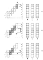
図3は、本実施形態の車両用前照灯システムの動作を説明するための概念図である。また、図4は、図3に示す動作の実行時における具体的な数値例を示す図である。車両用前照灯システムの基本的動作として、図3(A)〜図3(C)に示すように、各ランプユニット20R、20Lは、5つのゾーンA〜Eでそれぞれ個別に光照射を制御する。このとき、各ゾーンA〜Eの照射光は、それぞれ左右方向に幅nを有しており、かつ隣り合うゾーンが互いにn/2の幅で重なっている。具体的には、ゾーンAの右側とゾーンBの左側がn/2幅で重なり、ゾーンBの右側とゾーンCの左側がn/2幅で重なり、ゾーンCの右側とゾーンDの左側がn/2幅で重なり、ゾーンDの右側とゾーンEの左側がn/2幅で重なっている。なお、図中では説明のため各ゾーンを上下にずらして示しているが、実際には各ゾーンは、左右方向に列をなし、隣り合うもの同士が部分的に重なっている。また、各ゾーンへの光は、上記した図2にて示したように明るさを変えても左右幅がほとんど変化しないという特性を有している。
FIG. 3 is a conceptual diagram for explaining the operation of the vehicle headlamp system of the present embodiment. FIG. 4 is a diagram showing specific numerical examples at the time of executing the operation shown in FIG. As a basic operation of the vehicle headlamp system, as shown in FIGS. 3A to 3C, each of the
上記した各ゾーンA〜Eでそれぞれ個別に制御可能な照射光を用いることで、車両前方の仮想鉛直面における6つの分割領域(個別領域:Area)1〜6についてそれぞれ個別に光照射状態とし、または非照射状態とすることができる。具体的には、分割領域1への照射光は、ゾーンAへの照射光を用いて形成され、分割領域2への照射光は、ゾーンA、Bへの照射光を用いて形成され、分割領域3への照射光は、ゾーンB、Cへの照射光を用いて形成され、分割領域4への照射光は、ゾーンC、Dへの照射光を用いて形成され、分割領域5への照射光は、ゾーンD、Eへの照射光を用いて形成され、分割領域6への照射光は、ゾーンEへの照射光を用いて形成される。このため、各ゾーンA〜Eの全てに照射光が与えられている場合には、各ゾーンでの照射光の強度を仮に相対的数値として50と表したとすると、図4(A)〜図4(C)の各々における「全点灯時」の欄に示すように、分割領域1、6のそれぞれでの照射光の強度は50となり、分割領域2〜5のそれぞれでの照射光の強度は100となる。すなわち、全体としてみれば左右方向に配列された6つの分割領域のうち、中央寄りの分割領域2〜5での照射光が相対的により明るい状態となる。本実施形態ではこのような明るさ分布を理想的な配光パターンと想定している。
By using the irradiation light that can be individually controlled in each of the zones A to E described above, each of the six divided regions (individual regions: Area) 1 to 6 in the virtual vertical plane in front of the vehicle is individually in a light irradiation state, Or it can be set as a non-irradiation state. Specifically, the irradiation light to the divided
次に、前方車両が存在する場合における制御部12による配光制御について説明する。図3(A)に示すように、自車両から比較的遠くに前方車両100が存在し、分割領域3のみに入っているとする。このとき、光照射範囲設定部13は、分割領域3を非照射範囲(光を照射しない範囲)に設定し、それ以外の分割領域1、2、4〜6を光照射範囲に設定する。この場合に、分割領域3に照射光が与えられないようにするためには、図示のようにゾーンB,Cへの照射光をゼロにするか、あるいはゼロに等しい状態に減光すればよい。このときの各分割領域における明るさは、特に調整を施さないとすれば、図4(A)において「マスク時未調整」の欄で示すように、左側(分割領域1)から順に、50、50、0、50、100、50となる。しかし、この場合には非照射範囲とした分割領域3の両隣の分割領域2、4の明るさが50に低下してしまう。
Next, light distribution control by the
このため、本実施形態では、分割領域2、4の明るさの低下を防ぐために、図4(A)において「調整1」の欄で示すようにゾーンA、Dの照射光の明るさを100に設定する。それにより、各分割領域における明るさは左側(分割領域1)から順に、100、100、0、100、150、50となる。したがって、前方車両100の存在する領域の両側における照射光の明るさ低下を防ぐことができる。
For this reason, in this embodiment, in order to prevent the brightness of the divided
ここで、分割領域5の明るさが150と突出しているため、運転者に違和感を与える可能性もある。このため、明るさ分布がより均等になるように、他のゾーンの照射光の明るさについても調整することがより好ましい。一例として、図4(A)において「調整2」の欄で示すように、照射光の明るさをゾーンAでは100、ゾーンB、Cでは0、ゾーンDでは70、ゾーンEでは30と設定することができる。それにより、各分割領域における明るさは左側(分割領域1)から順に、100、100、0、70、100、30となる。この例では、前方車両100の存在する領域の両側の各2つの分割領域1、2、4、5における照射光の明るさをより均等にし、かつ前方車両から遠い分割領域6における照射光の明るさを相対的に低くすることで、運転者に対して違和感を与える可能性をより低減している。
Here, since the brightness of the divided
図3(B)に示すように、自車両から比較的近くに前方車両100が存在し、分割領域3と分割領域4に入っているとする。このとき、光照射範囲設定部13は、分割領域3、4を非照射範囲(光を照射しない範囲)に設定し、それ以外の分割領域1,2,5,6を光照射範囲に設定する。この場合に、分割領域3、4に照射光が与えられないようにするためには、図示のようにゾーンB、C、Dへの照射光をゼロにするか、あるいはゼロに等しい状態に減光する必要がある。このときの各分割領域における明るさは、特に調整を施さないとすれば、図4(B)において「マスク時未調整」の欄で示すように、左側(分割領域1)から順に、50、50、0、0、50、50となる。しかし、この場合には非照射範囲とした分割領域3、4の両隣の分割領域2、5の明るさが50に低下してしまう。
As shown in FIG. 3 (B), it is assumed that the
このため、本実施形態では、分割領域2、5の明るさの低下を防ぐために、図4(B)において「調整1」の欄で示すようにゾーンA、Eの照射光の明るさを100に設定する。それにより、各分割領域における明るさは左側(分割領域1)から順に、100、100、0、0、100、100となる。したがって、前方車両100の存在する領域の両側における照射光の明るさ低下を防ぐことができる。この場合には、特定の分割領域の明るさが突出しているということはないので、「調整2」の欄は「調整1」と同じとなる。すなわち、さらなる調整はしていない。
For this reason, in this embodiment, in order to prevent the brightness of the divided
図3(C)に示すように、自車両から比較的遠くに前方車両100が存在し、分割領域6のみに入っているとする。このとき、光照射範囲設定部13は、分割領域6を非照射範囲(光を照射しない範囲)に設定し、それ以外の分割領域1〜5を光照射範囲に設定する。この場合に、分割領域6に照射光が与えられないようにするためには、図示のようにゾーンEへの照射光をゼロにするか、あるいはゼロに等しい状態に減光すればよい。このときの各分割領域における明るさは、特に調整を施さないとすれば、図4(C)において「マスク時未調整」の欄で示すように、左側(分割領域1)から順に、50、100、100、100、50、0となる。しかし、この場合には非照射範囲とした分割領域6の隣の分割領域5の明るさが50に低下してしまう。
As shown in FIG. 3C, it is assumed that the
このため、本実施形態では、分割領域5の明るさの低下を防ぐために、図4(C)において「調整1」の欄で示すようにゾーンB、Dの照射光の明るさを100に設定し、ゾーンA、Cの照射光の明るさを0に設定する。それにより、各分割領域における明るさは左側(分割領域1)から順に、0、100、100、100、100、0となる。したがって、前方車両100の存在する領域の両側における照射光の明るさ低下を防ぐことができる。
For this reason, in this embodiment, in order to prevent the brightness of the divided
ここで、分割領域1の明るさが0と突出して暗いため、運転者に違和感を与える可能性もある。このため、明るさ分布がより均等になるように、他のゾーンの照射光の明るさについても調整することがより好ましい。一例として、図4(C)において「調整2」の欄で示すように、照射光の明るさをゾーンAでは20、ゾーンBでは80、ゾーンCでは20、ゾーンDでは90、ゾーンEでは0と設定することができる。それにより、各分割領域における明るさは左側(分割領域1)から順に、20、100、100、110、90、0となる。この例では、前方車両100の存在する領域の両側の各2つの分割領域2〜5における照射光の明るさをより均等にし、かつ前方車両から遠い分割領域1における照射光の明るさを相対的に低くしつつも0ではない状態とすることで、運転者に対して違和感を与える可能性をより低減している。
Here, since the brightness of the divided
なお、上記したいずれの例においても、調整1から調整2へ遷移するように配光制御してもよいし、調整1と調整2のいずれか一方のみで配光制御してもよい。
In any of the above-described examples, the light distribution control may be performed so that the transition from the
図5は、各ゾーンの明るさの切り替え方法について説明する図である。配光制御部14によって各ゾーンの明るさを切り替える際には、一瞬で切り替える場合のほか、図示のように時間をかけて切り替えることもできる。図5に示す例では、ゾーンAは時間をかけて明るくしており、ゾーンBは時間をかけて暗くしている。さらに、暗くするゾーンについては一瞬で切り替え、明るくするゾーンについては時間をかけて切り替えるようにしてもよい。
FIG. 5 is a diagram for explaining a method of switching the brightness of each zone. When the brightness of each zone is switched by the light
以上のような実施形態によれば、複数の光を部分的に重ね合わせることによって特定の領域への選択的な光照射が行われる車両用前照灯において、ある領域を非照射状態としたときにその領域に隣り合う領域に対応した光の明るさが増すように点灯制御が行われる。このため、車両前方の視認性をより向上させることが可能となる。 According to the embodiment as described above, in a vehicle headlamp that selectively irradiates a specific area by partially overlapping a plurality of lights, when a certain area is not irradiated The lighting control is performed so that the brightness of the light corresponding to the area adjacent to the area increases. For this reason, it becomes possible to improve the visibility ahead of vehicles.
なお、本発明は上述した実施形態の内容に限定されるものではなく、本発明の要旨の範囲内において種々に変形して実施をすることが可能である。例えば、5つのゾーンA〜Eでそれぞれ個別に照射光を制御する場合を例示していたが、ゾーン数はこれに限定されない。同様に、分割領域の数も6つに限定されない。 In addition, this invention is not limited to the content of embodiment mentioned above, In the range of the summary of this invention, it can change and implement variously. For example, although the case where irradiation light was individually controlled in each of the five zones A to E was illustrated, the number of zones is not limited to this. Similarly, the number of divided areas is not limited to six.
10:カメラ
11:車両検出部
12:制御部
13:光照射範囲設定部
14:配光制御部
20R、20L:ランプユニット
21:LED点灯回路
22:マトリクスLED
DESCRIPTION OF SYMBOLS 10: Camera 11: Vehicle detection part 12: Control part 13: Light irradiation range setting part 14: Light
Claims (4)
点灯制御装置と、
前記点灯制御装置によって制御される車両用前照灯と、
を含み、
前記点灯制御装置は、
前方車両の位置を検出する車両検出部と、
前記複数の領域のうち、前記前方車両の位置に応じた少なくとも1つの領域を光の非照射範囲として設定し、残りの領域を光照射範囲として設定する光照射範囲設定部と、
前記光照射範囲設定部によって設定される前記光照射範囲及び前記非照射範囲に対応した制御信号を生成して前記車両用前照灯へ出力する配光制御部と、
を含み、
前記複数の領域は、前記車両を基準とした左右方向において相互間に隙間なく配置されており、かつ、少なくとも、
前記車両を基準とした左右方向における左端に位置しており前記複数の照射ゾーンのうちの1つである第1照射ゾーンへの前記照射光の一部分で形成される左端領域と、
前記車両を基準とした左右方向における右端に位置しており前記複数の照射ゾーンのうちの1つである第2照射ゾーンへの前記照射光の一部分で形成される右端領域と、
前記左端領域と前記右端領域の間に位置しており、前記第1照射ゾーンと当該第1照射ゾーンの右隣の照射ゾーンの各々への前記照射光の一部分を重ねて形成される第1中間領域及び前記第2照射ゾーンと当該第2照射ゾーンの左隣の照射ゾーンの各々への前記照射光の一部分を重ねて形成される第2中間領域と、
を有し、
前記配光制御部は、前記複数の照射ゾーンのうちで、前記非照射領域に対応する照射ゾーンへの照射光を相対的に暗くするとともに、前記光照射領域であって前記非照射領域と隣り合う領域が前記第1中間領域又は前記第2中間領域である場合にこれらに対応する前記照射ゾーンである前記第1照射ゾーン若しくは前記右隣の照射ゾーン又は前記第2照射ゾーン若しくは前記左隣の照射ゾーンへの照射光の各一部分の重ね合わせによる照射光を相対的に明るくするようにして前記制御信号を生成する、
車両用前照灯システム。 A vehicle can individually light irradiation for each of a plurality of irradiation zones arranged in the lateral direction with respect to the, selective light irradiation for a plurality of regions by using the irradiation light to the plurality of irradiation zones A vehicle headlamp system that can be performed,
A lighting control device;
A vehicle headlamp controlled by the lighting control device;
Including
The lighting control device includes:
A vehicle detection unit for detecting the position of the preceding vehicle;
Among the plurality of regions, the set of at least one realm according to the position of the forward vehicle as a non-irradiation range of light, a light irradiation range setting unit for setting the remaining realm as the light irradiation range,
A light distribution control unit that generates a control signal corresponding to the light irradiation range and the non-irradiation range set by the light irradiation range setting unit and outputs the control signal to the vehicle headlamp;
Including
The plurality of regions are arranged without gaps in the left-right direction with respect to the vehicle, and at least,
A left end region formed by a part of the irradiation light to the first irradiation zone located at the left end in the left-right direction with respect to the vehicle and being one of the plurality of irradiation zones;
A right end region formed by a part of the irradiation light to a second irradiation zone which is located at a right end in a left-right direction with respect to the vehicle and is one of the plurality of irradiation zones;
A first intermediate located between the left end region and the right end region and formed by overlapping a part of the irradiation light to each of the first irradiation zone and the irradiation zone adjacent to the right of the first irradiation zone. A second intermediate region formed by overlapping a portion of the irradiation light to each of the region and the second irradiation zone and the irradiation zone adjacent to the left of the second irradiation zone;
Have
The light distribution control unit, among the plurality of irradiation zones, the relatively with dim light irradiated to the irradiation zone corresponding to the non-irradiated region, adjacent to the non-irradiated areas a said light irradiation area When the matching region is the first intermediate region or the second intermediate region, the irradiation zone corresponding to the first irradiation zone or the right irradiation zone or the second irradiation zone or the left neighbor Generating the control signal so as to relatively brighten the irradiation light by overlapping each part of the irradiation light to the irradiation zone ;
Vehicle headlamp system .
前記第2照射ゾーンと前記左隣の照射ゾーンの各々の前記左右方向における幅の略1/2の部分同士が重なり合うことで前記第2中間領域に対する光照射が行われる、 Light irradiation is performed on the second intermediate region by overlapping approximately half of the width in the left-right direction of each of the second irradiation zone and the left irradiation zone.
請求項1に記載の車両用前照灯システム。 The vehicle headlamp system according to claim 1.
請求項1又は2に記載の車両用前照灯システム。 The vehicle headlamp system according to claim 1 or 2.
請求項3に記載の車両用灯具システム。 The vehicular lamp system according to claim 3.
Priority Applications (2)
| Application Number | Priority Date | Filing Date | Title |
|---|---|---|---|
| JP2015099427A JP6571384B2 (en) | 2015-05-14 | 2015-05-14 | Lighting control device for vehicle headlamp, vehicle headlamp system |
| US15/140,224 US9751455B2 (en) | 2015-05-14 | 2016-04-27 | Headlight controller and vehicle headlight system |
Applications Claiming Priority (1)
| Application Number | Priority Date | Filing Date | Title |
|---|---|---|---|
| JP2015099427A JP6571384B2 (en) | 2015-05-14 | 2015-05-14 | Lighting control device for vehicle headlamp, vehicle headlamp system |
Publications (2)
| Publication Number | Publication Date |
|---|---|
| JP2016215692A JP2016215692A (en) | 2016-12-22 |
| JP6571384B2 true JP6571384B2 (en) | 2019-09-04 |
Family
ID=57276551
Family Applications (1)
| Application Number | Title | Priority Date | Filing Date |
|---|---|---|---|
| JP2015099427A Active JP6571384B2 (en) | 2015-05-14 | 2015-05-14 | Lighting control device for vehicle headlamp, vehicle headlamp system |
Country Status (2)
| Country | Link |
|---|---|
| US (1) | US9751455B2 (en) |
| JP (1) | JP6571384B2 (en) |
Families Citing this family (14)
| Publication number | Priority date | Publication date | Assignee | Title |
|---|---|---|---|---|
| JP6265183B2 (en) * | 2015-08-21 | 2018-01-24 | トヨタ自動車株式会社 | Vehicle headlamp device |
| JP6815696B2 (en) * | 2016-12-27 | 2021-01-20 | ダイハツ工業株式会社 | Headlights for driving vehicles |
| JP6872413B2 (en) * | 2017-04-28 | 2021-05-19 | 株式会社小糸製作所 | Vehicle lighting |
| JP7099842B2 (en) * | 2018-03-23 | 2022-07-12 | スタンレー電気株式会社 | Headlight device for vehicles |
| US10611294B2 (en) * | 2018-06-29 | 2020-04-07 | Valeo North America, Inc. | Front lighting systems and methods |
| JP7187291B2 (en) * | 2018-12-14 | 2022-12-12 | 株式会社小糸製作所 | Infrared camera system and vehicle |
| DE102019108505A1 (en) * | 2019-04-02 | 2020-10-08 | Claas E-Systems Gmbh | Agricultural work machine |
| DE102020116224A1 (en) * | 2019-06-20 | 2020-12-24 | Hyundai Mobis Co., Ltd. | Headlights for a vehicle and method of controlling the same |
| CN114303027B (en) | 2019-08-28 | 2025-04-25 | 株式会社小糸制作所 | Vehicle lighting |
| CN118906976A (en) * | 2019-10-10 | 2024-11-08 | 株式会社小糸制作所 | Vehicle position detection device, vehicle lamp system, and vehicle position detection method |
| FR3104885B1 (en) * | 2019-12-13 | 2022-08-05 | Valeo Vision | Image data management method and automobile lighting device |
| DE102020007757A1 (en) * | 2020-12-18 | 2021-02-25 | Daimler Ag | Method for adjusting vehicle lighting when driving on a construction site and vehicle |
| CN117098691A (en) * | 2021-03-29 | 2023-11-21 | 法雷奥照明公司 | Method for controlling light patterns and automotive lighting equipment |
| JP2024072556A (en) * | 2022-11-16 | 2024-05-28 | 三菱自動車工業株式会社 | Vehicle lighting device |
Family Cites Families (13)
| Publication number | Priority date | Publication date | Assignee | Title |
|---|---|---|---|---|
| US7156542B2 (en) * | 2002-12-13 | 2007-01-02 | Ford Global Technologies, Llc | Vehicle headlight system having digital beam-forming optics |
| CZ302547B6 (en) * | 2005-07-04 | 2011-07-07 | Visteon Global Technologies, Inc. | Adaptive headlight system of motor vehicles |
| JP4624257B2 (en) * | 2005-12-28 | 2011-02-02 | 株式会社小糸製作所 | Vehicle lighting |
| JP2008189276A (en) * | 2007-02-08 | 2008-08-21 | Koito Mfg Co Ltd | Vehicular lamp system |
| JP4613970B2 (en) * | 2008-03-12 | 2011-01-19 | トヨタ自動車株式会社 | Vehicle lighting device |
| US20100020170A1 (en) * | 2008-07-24 | 2010-01-28 | Higgins-Luthman Michael J | Vehicle Imaging System |
| JP5622494B2 (en) | 2010-09-09 | 2014-11-12 | スタンレー電気株式会社 | Light emitting device and manufacturing method thereof |
| JP5692520B2 (en) | 2011-03-14 | 2015-04-01 | スタンレー電気株式会社 | Lamp unit |
| DE102011017644A1 (en) * | 2011-04-28 | 2012-10-31 | Robert Bosch Gmbh | Method for controlling a headlight system of a vehicle and device for controlling a headlight system of a vehicle |
| JP2013246968A (en) * | 2012-05-25 | 2013-12-09 | Koito Mfg Co Ltd | Vehicle lamp |
| JP6274767B2 (en) * | 2013-07-11 | 2018-02-07 | 株式会社小糸製作所 | Light distribution control device for vehicle headlamp |
| JP6370533B2 (en) * | 2013-07-11 | 2018-08-08 | 株式会社小糸製作所 | Light distribution control method and light distribution control device for vehicle headlamp |
| JP6218499B2 (en) | 2013-08-23 | 2017-10-25 | スタンレー電気株式会社 | Lighting control device for vehicle headlamp, vehicle headlamp system |
-
2015
- 2015-05-14 JP JP2015099427A patent/JP6571384B2/en active Active
-
2016
- 2016-04-27 US US15/140,224 patent/US9751455B2/en active Active
Also Published As
| Publication number | Publication date |
|---|---|
| US9751455B2 (en) | 2017-09-05 |
| JP2016215692A (en) | 2016-12-22 |
| US20160332560A1 (en) | 2016-11-17 |
Similar Documents
| Publication | Publication Date | Title |
|---|---|---|
| JP6571384B2 (en) | Lighting control device for vehicle headlamp, vehicle headlamp system | |
| JP6218499B2 (en) | Lighting control device for vehicle headlamp, vehicle headlamp system | |
| JP5992278B2 (en) | Lighting control device for vehicle headlamp, vehicle headlamp system | |
| EP2821282B1 (en) | Light source apparatus, vehicle headlamp and vehicle headlamp system | |
| EP2826667B1 (en) | Vehicle headlamp and vehicle headlamp system | |
| EP2567867B1 (en) | Vehicle headlamp and system for controlling the same | |
| JP6663168B2 (en) | Vehicle headlamp lighting control device, vehicle headlamp system | |
| JP6215882B2 (en) | Vehicle lamp and vehicle lamp system | |
| JP6889588B2 (en) | Vehicle lighting | |
| US20150003100A1 (en) | Light-emitting apparatus and vehicle headlamp system | |
| JP2015016773A (en) | Light distribution control method and light distribution control device for vehicle headlamp | |
| JP6545496B2 (en) | Lighting control device for vehicular headlamp, vehicular headlamp system | |
| JP2016083987A (en) | Vehicular lighting system and on-vehicle system | |
| JP2013077451A (en) | Headlight device for vehicle | |
| JP2016015332A (en) | Vehicle headlamp device and vehicle headlamp control system | |
| JP7052165B2 (en) | Headlight controller | |
| JP2015116915A (en) | Lighting control device of headlight for vehicle, and headlight system for vehicle | |
| JP2014101069A (en) | Lighting control unit of vehicular headlamps, and vehicular headlamp system | |
| JP2013147111A (en) | Lighting control device for vehicle front light, and vehicle front light system | |
| JP2013154741A (en) | Lighting controller of vehicle headlight and vehicle headlight system | |
| JP5882755B2 (en) | Lighting control device for vehicle headlamp, vehicle headlamp system | |
| JP2015033954A (en) | Lighting control device for vehicle headlamp, vehicle headlamp system | |
| US12409775B2 (en) | Vehicle headlamp having a lamp unit with a matrix of light emitting units emitting a plurality of irradiation spots and a boundary determination unit and control unit controlling the boundary illuminance | |
| JP2017137026A (en) | Vehicle headlight system | |
| JP6162012B2 (en) | Lighting control device for vehicle headlamp, vehicle headlamp system |
Legal Events
| Date | Code | Title | Description |
|---|---|---|---|
| A621 | Written request for application examination |
Free format text: JAPANESE INTERMEDIATE CODE: A621 Effective date: 20180405 |
|
| A977 | Report on retrieval |
Free format text: JAPANESE INTERMEDIATE CODE: A971007 Effective date: 20190215 |
|
| A131 | Notification of reasons for refusal |
Free format text: JAPANESE INTERMEDIATE CODE: A131 Effective date: 20190225 |
|
| A521 | Request for written amendment filed |
Free format text: JAPANESE INTERMEDIATE CODE: A523 Effective date: 20190424 |
|
| TRDD | Decision of grant or rejection written | ||
| A01 | Written decision to grant a patent or to grant a registration (utility model) |
Free format text: JAPANESE INTERMEDIATE CODE: A01 Effective date: 20190802 |
|
| A61 | First payment of annual fees (during grant procedure) |
Free format text: JAPANESE INTERMEDIATE CODE: A61 Effective date: 20190808 |
|
| R150 | Certificate of patent or registration of utility model |
Ref document number: 6571384 Country of ref document: JP Free format text: JAPANESE INTERMEDIATE CODE: R150 |
|
| R250 | Receipt of annual fees |
Free format text: JAPANESE INTERMEDIATE CODE: R250 |
|
| R250 | Receipt of annual fees |
Free format text: JAPANESE INTERMEDIATE CODE: R250 |
|
| R250 | Receipt of annual fees |
Free format text: JAPANESE INTERMEDIATE CODE: R250 |
|
| R250 | Receipt of annual fees |
Free format text: JAPANESE INTERMEDIATE CODE: R250 |