JP6571266B2 - Imaging device - Google Patents
Imaging device Download PDFInfo
- Publication number
- JP6571266B2 JP6571266B2 JP2018502932A JP2018502932A JP6571266B2 JP 6571266 B2 JP6571266 B2 JP 6571266B2 JP 2018502932 A JP2018502932 A JP 2018502932A JP 2018502932 A JP2018502932 A JP 2018502932A JP 6571266 B2 JP6571266 B2 JP 6571266B2
- Authority
- JP
- Japan
- Prior art keywords
- image
- focus position
- imaging device
- pattern
- modulator
- Prior art date
- Legal status (The legal status is an assumption and is not a legal conclusion. Google has not performed a legal analysis and makes no representation as to the accuracy of the status listed.)
- Active
Links
Images


Classifications
-
- G—PHYSICS
- G02—OPTICS
- G02B—OPTICAL ELEMENTS, SYSTEMS OR APPARATUS
- G02B7/00—Mountings, adjusting means, or light-tight connections, for optical elements
- G02B7/28—Systems for automatic generation of focusing signals
- G02B7/34—Systems for automatic generation of focusing signals using different areas in a pupil plane
-
- G—PHYSICS
- G02—OPTICS
- G02B—OPTICAL ELEMENTS, SYSTEMS OR APPARATUS
- G02B5/00—Optical elements other than lenses
- G02B5/18—Diffraction gratings
- G02B5/1814—Diffraction gratings structurally combined with one or more further optical elements, e.g. lenses, mirrors, prisms or other diffraction gratings
-
- G—PHYSICS
- G02—OPTICS
- G02B—OPTICAL ELEMENTS, SYSTEMS OR APPARATUS
- G02B26/00—Optical devices or arrangements for the control of light using movable or deformable optical elements
- G02B26/02—Optical devices or arrangements for the control of light using movable or deformable optical elements for controlling the intensity of light
-
- G—PHYSICS
- G02—OPTICS
- G02B—OPTICAL ELEMENTS, SYSTEMS OR APPARATUS
- G02B27/00—Optical systems or apparatus not provided for by any of the groups G02B1/00 - G02B26/00, G02B30/00
- G02B27/42—Diffraction optics, i.e. systems including a diffractive element being designed for providing a diffractive effect
- G02B27/4272—Diffraction optics, i.e. systems including a diffractive element being designed for providing a diffractive effect having plural diffractive elements positioned sequentially along the optical path
-
- G—PHYSICS
- G02—OPTICS
- G02B—OPTICAL ELEMENTS, SYSTEMS OR APPARATUS
- G02B27/00—Optical systems or apparatus not provided for by any of the groups G02B1/00 - G02B26/00, G02B30/00
- G02B27/60—Systems using moiré fringes
-
- G—PHYSICS
- G02—OPTICS
- G02B—OPTICAL ELEMENTS, SYSTEMS OR APPARATUS
- G02B7/00—Mountings, adjusting means, or light-tight connections, for optical elements
- G02B7/28—Systems for automatic generation of focusing signals
-
- H—ELECTRICITY
- H04—ELECTRIC COMMUNICATION TECHNIQUE
- H04N—PICTORIAL COMMUNICATION, e.g. TELEVISION
- H04N23/00—Cameras or camera modules comprising electronic image sensors; Control thereof
-
- H—ELECTRICITY
- H04—ELECTRIC COMMUNICATION TECHNIQUE
- H04N—PICTORIAL COMMUNICATION, e.g. TELEVISION
- H04N23/00—Cameras or camera modules comprising electronic image sensors; Control thereof
- H04N23/60—Control of cameras or camera modules
-
- H—ELECTRICITY
- H04—ELECTRIC COMMUNICATION TECHNIQUE
- H04N—PICTORIAL COMMUNICATION, e.g. TELEVISION
- H04N23/00—Cameras or camera modules comprising electronic image sensors; Control thereof
- H04N23/60—Control of cameras or camera modules
- H04N23/67—Focus control based on electronic image sensor signals
- H04N23/671—Focus control based on electronic image sensor signals in combination with active ranging signals, e.g. using light or sound signals emitted toward objects
-
- H—ELECTRICITY
- H04—ELECTRIC COMMUNICATION TECHNIQUE
- H04N—PICTORIAL COMMUNICATION, e.g. TELEVISION
- H04N23/00—Cameras or camera modules comprising electronic image sensors; Control thereof
- H04N23/60—Control of cameras or camera modules
- H04N23/67—Focus control based on electronic image sensor signals
- H04N23/673—Focus control based on electronic image sensor signals based on contrast or high frequency components of image signals, e.g. hill climbing method
-
- H—ELECTRICITY
- H04—ELECTRIC COMMUNICATION TECHNIQUE
- H04N—PICTORIAL COMMUNICATION, e.g. TELEVISION
- H04N23/00—Cameras or camera modules comprising electronic image sensors; Control thereof
- H04N23/80—Camera processing pipelines; Components thereof
-
- G—PHYSICS
- G06—COMPUTING; CALCULATING OR COUNTING
- G06T—IMAGE DATA PROCESSING OR GENERATION, IN GENERAL
- G06T2207/00—Indexing scheme for image analysis or image enhancement
- G06T2207/20—Special algorithmic details
- G06T2207/20048—Transform domain processing
- G06T2207/20056—Discrete and fast Fourier transform, [DFT, FFT]
-
- G—PHYSICS
- G06—COMPUTING; CALCULATING OR COUNTING
- G06T—IMAGE DATA PROCESSING OR GENERATION, IN GENERAL
- G06T5/00—Image enhancement or restoration
- G06T5/10—Image enhancement or restoration by non-spatial domain filtering
Description
本発明は、撮像装置に関し、特に撮像装置の高機能化に有効な技術に関する。 The present invention relates to an imaging apparatus, and more particularly to a technique effective for enhancing the functionality of the imaging apparatus.
スマートフォンなどに搭載するデジタルカメラや車載カメラ等は、薄型化・高機能化が必要である。この種のデジタルカメラの薄型化技術としては、例えばレンズを用いることなく物体像を得るものがある(例えば特許文献1参照)。
この技術は、画像センサに特殊な回折格子基板を貼り付け、回折格子基板を透過する光が画像センサ上で生じる射影パターンから、入射光の入射角を逆問題により求めることで、外界の物体の像を得るものである。Digital cameras and in-vehicle cameras mounted on smartphones, etc. need to be thinner and more functional. As a technique for reducing the thickness of this type of digital camera, for example, there is a technique for obtaining an object image without using a lens (see, for example, Patent Document 1).
In this technology, a special diffraction grating substrate is attached to the image sensor, and the incident angle of the incident light is obtained by an inverse problem from the projection pattern in which the light transmitted through the diffraction grating substrate is generated on the image sensor. Obtain an image.
上述した特許文献1では、画像センサに貼り付ける基板上面に形成する回折格子のパターンが渦巻き状などの特殊な格子パターンとなっている。そして、その画像センサにて受光される射影パターンから、像を再生するための逆問題を解くことにより、物体の像を得ているが、この逆問題を解く際の演算が複雑になるという問題がある。またデジタルカメラ、車載カメラは高機能なセンシングが求められるが、特許文献1の技術は高機能化を考慮していない。
本発明の目的は、簡単な演算を用いた、撮像装置の高機能化を可能とする技術を提供することにある。In
An object of the present invention is to provide a technique that enables high functionality of an image pickup apparatus using simple calculation.
上記課題は、たとえば、特許請求の範囲に記載の発明により解決される。 The above-described problems are solved by, for example, the invention described in the claims.
本発明によれば、撮影後のフォーカス調整(リフォーカス)、オートフォーカス、測距といった高機能な撮像装置を実現することが可能となる。 According to the present invention, it is possible to realize a highly functional image pickup apparatus such as focus adjustment (refocus), autofocus, and distance measurement after shooting.
以下の実施の形態においては便宜上その必要があるときは、複数のセクションまたは実施の形態に分割して説明するが、特に明示した場合を除き、それらはお互いに無関係なものではなく、一方は他方の一部または全部の変形例、詳細、補足説明等の関係にある。
また、以下の実施の形態において、要素の数等(個数、数値、量、範囲等を含む)に言及する場合、特に明示した場合および原理的に明らかに特定の数に限定される場合等を除き、その特定の数に限定されるものではなく、特定の数以上でも以下でもよい。
さらに、以下の実施の形態において、その構成要素(要素ステップ等も含む)は、特に明示した場合および原理的に明らかに必須であると考えられる場合等を除き、必ずしも必須のものではないことは言うまでもない。In the following embodiments, when it is necessary for the sake of convenience, the description will be divided into a plurality of sections or embodiments. However, unless otherwise specified, they are not irrelevant to each other. There are some or all of the modifications, details, supplementary explanations, and the like.
Further, in the following embodiments, when referring to the number of elements (including the number, numerical value, quantity, range, etc.), especially when clearly indicated and when clearly limited to a specific number in principle, etc. Except, it is not limited to the specific number, and may be more or less than the specific number.
Further, in the following embodiments, the constituent elements (including element steps and the like) are not necessarily indispensable unless otherwise specified and apparently essential in principle. Needless to say.
同様に、以下の実施の形態において、構成要素等の形状、位置関係等に言及するときは特に明示した場合および原理的に明らかにそうではないと考えられる場合等を除き、実質的にその形状等に近似または類似するもの等を含むものとする。このことは、上記数値および範囲についても同様である。
また、実施の形態を説明するための全図において、同一の部材には原則として同一の符号を付し、その繰り返しの説明は省略する。
以下、本発明の実施例について図面を用いて説明する。Similarly, in the following embodiments, when referring to the shape, positional relationship, etc. of components, etc., the shape of the component is substantially the case unless it is clearly specified and the case where it is clearly not apparent in principle. And the like are included. The same applies to the above numerical values and ranges.
In all the drawings for explaining the embodiments, the same members are denoted by the same reference symbols in principle, and the repeated explanation thereof is omitted.
Embodiments of the present invention will be described below with reference to the drawings.
〈無限遠物体の撮影原理〉
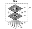
図1は、本実施の形態1による撮像装置101における構成の一例を示す説明図である。撮像装置101は、結像させるレンズを用いることなく、外界の物体の画像を取得するものであり、図1に示すように、変調器102、画像センサ103、および画像処理部106から構成されている。<Principle of shooting an object at infinity>
FIG. 1 is an explanatory diagram illustrating an example of a configuration of the
図2に変調器102の一例を示す。変調器102は、画像センサ103の受光面に密着して固定されており、格子基板102aに第1の格子パターン104、第2の格子パターン105がそれぞれ形成された構成からなる。格子基板102aは、例えばガラスやプラスティックなどの透明な材料からなる。以降、格子基板102aの画像センサ103側を裏面と呼び、対向する面すなわち撮影対象側を表面と呼ぶ。この格子パターン104、105は、外側に向かうほど中心からの半径に反比例して格子パターンの間隔、すなわちピッチが狭くなる同心円状の格子パターンからなる。格子パターン104,105は、例えば半導体プロセスに用いられるスパッタリング法などによってアルミニウムなどを蒸着することによって形成される。アルミニウムが蒸着されたパターンと蒸着されていないパターンによって濃淡がつけられる。なお、格子パターン104,105の形成は、これに限定されるものでなく、例えばインクジェットプリンタなどによる印刷などによって濃淡をつけて形成してもよい。
An example of the
なお、ここでは変調器102を実現するために、格子パターン104,105を格子基板102aに形成する方法について述べたが、図3に示すように格子パターン104,105を薄膜に形成し、支持部材102bにより保持する構成などによっても実現できる。
格子パターン104,105を透過する光は、その格子パターンによって光の強度が変調される。透過した光は、画像センサ103にて受光される。画像センサ103は、例えばCCD(Charge Coupled Device)イメージセンサまたはCMOS(Complementary Metal Oxide Semiconductor)イメージセンサなどからなる。Here, in order to realize the
The intensity of light transmitted through the
画像センサ103の表面には、受光素子である画素103aが格子状に規則的に配置されている。この画像センサ103は、画素103aが受光した光画像を電気信号である画像信号に変換する。画像センサ103から出力された画像信号は、画像処理部である画像処理部106によって画像処理されて画像表示部107などに出力される。
On the surface of the
図4は、図1の撮像装置101による撮影の一例を示す説明図である。この図4では、撮像装置101によって被写体401を撮影して画像表示部107に表示している例を示している。図示するように、被写体401を撮影する際には、被写体401に対して変調器102における表面、具体的には第1の格子パターン104が形成されている格子基板102aの面が正対するようにして撮影が行われる。
続いて、画像処理部106による画像処理の概略について説明する。図5は、図1の撮像装置101が有する画像処理部106による画像処理の概略を示すフローチャートである。FIG. 4 is an explanatory diagram showing an example of shooting by the
Next, an outline of image processing by the
まず、画像センサ103から出力されるモアレ縞画像に対して、カラーのRGB(Red Green Blue)成分ごとに2次元フーリエ変換(FFT:Fast Fourier Transform)演算を行い、周波数スペクトルを求める(ステップS501)。続いて、ステップS501の処理による周波数スペクトルの片側周波数のデータを切り出した後(ステップS502)、該周波数スペクトルの強度計算を行う(ステップS503)ことによって画像を取得する。そして、得られた画像に対してノイズ除去処理を行い(ステップS504)、続いてコントラスト強調処理(ステップS505)などを行う。その後、画像のカラーバランスを調整して(ステップS506)撮影画像として出力する。以上により、画像処理部106による画像処理が終了となる。
First, a two-dimensional Fourier transform (FFT) operation is performed for each color RGB (Red Green Blue) component on the moire fringe image output from the
続いて、撮像装置101における撮影原理について説明する。まず、中心からの半径に対して反比例してピッチが細かくなる同心円状の格子パターン104,105は、以下のように定義する。レーザ干渉計などにおいて、平面波に近い球面波と参照光として用いる平面波とを干渉させる場合を想定する。同心円の中心である基準座標からの半径をrとし、そこでの球面波の位相をφ(r)とするとき、これを波面の曲がりの大きさを決める係数βを用いて、
Next, the imaging principle in the
![]()
![]()
と表せる。 It can be expressed.
球面波にもかかわらず、半径rの2乗で表されているのは、平面波に近い球面波のため、展開の最低次のみで近似できるからである。この位相分布を持った光に平面波を干渉させると、 In spite of the spherical wave, the reason why it is represented by the square of the radius r is that it can be approximated only by the lowest order of expansion because it is a spherical wave close to a plane wave. When plane waves interfere with light with this phase distribution,
![]()
![]()
のような干渉縞の強度分布が得られる。これは、 The interference fringe intensity distribution is obtained. this is,
![]()
![]()
を満たす半径位置で明るい線を持つ同心円の縞となる。縞のピッチをpとすると、 Concentric fringes with bright lines at radial positions that satisfy. If the pitch of the stripes is p,

が得られ、ピッチは、半径に対して反比例して狭くなっていくことがわかる。このような縞を持つプレートは、フレネルゾーンプレートやガボールゾーンプレートと呼ばれる。このように定義される強度分布に比例した透過率分布をもった格子パターンを、図1に示した格子パターン104,105として用いる。
It can be seen that the pitch decreases in inverse proportion to the radius. A plate having such stripes is called a Fresnel zone plate or a Gabor zone plate. A lattice pattern having a transmittance distribution proportional to the intensity distribution defined as described above is used as the
このような格子パターンが両面に形成された厚さtの変調器102に、図6に示すように角度θ0で平行光が入射したとする。変調器102中の屈折角をθとして幾何光学的には、表面の格子の透過率が乗じられた光が、δ=t・tanθだけずれて裏面に入射し、仮に2つの同心円格子の中心がそろえて形成されていたとすると、裏面の格子の透過率がδだけずれて掛け合わされることになる。このとき、
It is assumed that parallel light is incident at an angle θ0 as shown in FIG. 6 on a
のような強度分布が得られる。 An intensity distribution such as is obtained.
この展開式の第4項が、2つの格子のずれの方向にまっすぐな等間隔の縞模様を重なり合った領域一面に作ることがわかる。このような縞と縞の重ね合わせによって相対的に低い空間周波数で生じる縞はモアレ縞と呼ばれる。このようにまっすぐな等間隔の縞は、検出画像の2次元フーリエ変換によって得られる空間周波数分布に鋭いピークを生じる。その周波数の値からδの値、すなわち光線の入射角θを求めることが可能となる。このような全面で一様に等間隔で得られるモアレ縞は、同心円状の格子配置の対称性から、ずれの方向によらず同じピッチで生じることは明らかである。このような縞が得られるのは、格子パターンをフレネルゾーンプレートまたはガボールゾーンプレートで形成したことによるものであり、これ以外の格子パターンで、全面で一様な縞を得るのは困難と考えられる。但し、全面で一様に等間隔なモアレ縞が得ることが目的であり、格子パターンをフレネルゾーンプレートやガボールゾーンプレート
に限定するものではない。It can be seen that the fourth term of the unfolding formula creates a straight strip with equal intervals in the direction of displacement of the two gratings over the entire region. Such a fringe generated at a relatively low spatial frequency by overlapping the fringes is called a moire fringe. Such straight equidistant fringes cause sharp peaks in the spatial frequency distribution obtained by two-dimensional Fourier transform of the detected image. The value of δ, that is, the incident angle θ of the light beam can be obtained from the frequency value. It is clear that the moire fringes obtained at such uniform intervals on the entire surface are generated at the same pitch regardless of the direction of displacement, due to the symmetry of the concentric lattice arrangement. Such fringes are obtained because the lattice pattern is formed by a Fresnel zone plate or a Gabor zone plate, and it is considered difficult to obtain uniform stripes on the entire surface with other lattice patterns. . However, the purpose is to obtain moire fringes that are uniformly spaced on the entire surface, and the lattice pattern is not limited to the Fresnel zone plate or the Gabor zone plate.
第2項でもフレネルゾーンプレートの強度がモアレ縞で変調された縞が生じることがわかるが、2つの縞の積の周波数スペクトルは、それぞれのフーリエスペクトルのコンボリューションとなるため、鋭いピークは得られない。
式5から鋭いピークを持つ成分のみをIn the second term, it can be seen that fringes whose intensity of the Fresnel zone plate is modulated by moire fringes are generated, but the frequency spectrum of the product of the two fringes is a convolution of the respective Fourier spectra, so a sharp peak is obtained. Absent.
Only components with sharp peaks from Equation 5
![]()
![]()
のように取り出すと、そのフーリエスペクトルは、 And the Fourier spectrum is
のようになる。ここで、Fはフーリエ変換の演算を表し、u、vは、x方向およびy方向の空間周波数座標、括弧を伴うδはデルタ関数である。この結果から、検出画像の空間周波数スペクトルにおいて、モアレ縞の空間周波数のピークがu=±δβ/πの位置に生じることがわかる。 become that way. Here, F represents a Fourier transform operation, u and v are spatial frequency coordinates in the x and y directions, and δ with parentheses is a delta function. From this result, it can be seen that the spatial frequency peak of moire fringes occurs at the position of u = ± δβ / π in the spatial frequency spectrum of the detected image.
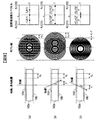
その様子を図7に示す。図7において、左から右にかけては、光線と変調器102の配置図、モアレ縞、および空間周波数スペクトルの模式図をそれぞれ示している。図7(a)は、垂直入射、図7(b)は、左側から角度θで光線が入射する場合、図7(c)は、右側から角度θで光線が入射する場合をそれぞれ示している。
変調器102の表面側に形成された第1の格子パターン104と裏面側に形成された第2の格子パターン105とは、軸がそろっている。図7(a)では、第1の格子パターン104と第2の格子パターン105との影が一致するのでモアレ縞は生じない。This is shown in FIG. In FIG. 7, from left to right, there are shown a layout diagram of light beams and a
The first
図7(b)および図7(c)では、第1の格子パターン104と第2の格子パターン105とのずれが等しいために同じモアレが生じ、空間周波数スペクトルのピーク位置も一致して、空間周波数スペクトルからは、光線の入射角が図7(b)の場合なのか、あるいは図7(c)の場合なのかを判別することができなくなる。
In FIG. 7B and FIG. 7C, the same moiré occurs because the shift between the
これを避けるためには、例えば図8に示すように、変調器102に垂直に入射する光線に対しても2つの格子パターンの影がずれて重なるようあらかじめ2つの格子パターン104,105を光軸に対して相対的にずらしておくことが必要である。軸上の垂直入射平面波に対して2つの格子の影の相対的なずれをδ0とするとき、入射角θの平面波によって生じるずれδは、
In order to avoid this, for example, as shown in FIG. 8, the two
![]()
![]()
のように表せる。このとき、入射角θの光線のモアレ縞の空間周波数スペクトルのピークは周波数のプラス側では It can be expressed as At this time, the peak of the spatial frequency spectrum of the moire fringes of the light beam with the incident angle θ is on the plus side of the frequency.
の位置となる。画像センサの大きさをS、画像センサのx方向およびy方向の画素数を共にNとすると、高速フーリエ変換(FFT:Fast Fourier Transform)による離散画像の空間周波数スペクトルは、−N/(2S)から+N/(2S)の範囲で得られる。このことから、プラス側の入射角とマイナス側の入射角を均等に受光することを考えれば、垂直入射平面波(θ=0)によるモアレ縞のスペクトルピーク位置は、原点(DC:直流成分)位置と、例えば+側端の周波数位置との中央位置、すなわち、 It becomes the position. Assuming that the size of the image sensor is S and the number of pixels in the x direction and y direction of the image sensor is N, the spatial frequency spectrum of a discrete image by Fast Fourier Transform (FFT) is −N / (2S). To + N / (2S). From this, considering that the positive incident angle and the negative incident angle are received evenly, the spectral peak position of the moire fringe due to the vertical incident plane wave (θ = 0) is the origin (DC: DC component) position. And, for example, the center position of the frequency position on the + side end, that is,
の空間周波数位置とするのが妥当である。したがって、2つの格子の相対的な中心位置ずれは、 It is reasonable to use the spatial frequency position of. Therefore, the relative center displacement of the two grids is
とするのが妥当である。 Is reasonable.
図9は、第1の格子パターン104と第2の格子パターン105とをずらして配置した場合のモアレ縞の生成および周波数スペクトルを説明する模式図である。図7と同様にして、左側は光線と変調器102の配置図、中央列はモアレ縞、そして右側は空間周波数スペクトルを示す。また、図9(a)は、光線が垂直入射の場合であり、図9(b)は、光線が左側から角度θで入射する場合であり、図9(c)は、光線が右側から角度θで入射する場合である。
FIG. 9 is a schematic diagram for explaining the generation of moire fringes and the frequency spectrum when the first
第1の格子パターン104と第2の格子パターン105とは、あらかじめδ0だけずらして配置されている。そのため、図9(a)でもモアレ縞が生じ、空間周波数スペクトルにピークが現れる。そのずらし量δ0は、上記したとおり、ピーク位置が原点から片側のスペクトル範囲の中央に現れるように設定されている。このとき図9(b)では、ずれδがさらに大きくなる方向、図9(c)では、小さくなる方向となっているため、図7と異なり、図9(b)と図9(c)との違いがスペクトルのピーク位置から判別できる。このピークのスペクトル像がすなわち無限遠の光束を示す輝点であり、図1の撮像装置101による撮影像にほかならない。
受光できる平行光の入射角の最大角度をθmaxとすると、The
When the maximum incident angle of parallel light that can be received is θmax,
より、撮像装置101にて受光できる最大画角は、
Therefore, the maximum angle of view that can be received by the
で与えられる。 Given in.
一般的なレンズを用いた結像との類推から、画角θmaxの平行光を画像センサの端で焦点を結んで受光すると考えると、レンズを用いない撮像装置101の実効的な焦点距離は、
From the analogy with image formation using a general lens, if it is assumed that parallel light having an angle of view θmax is focused at the end of the image sensor and received, the effective focal length of the
に相当すると考えることができる。
ここで、式13より画角は変調器102の厚さt、格子パターン104,105の係数βによって変更可能であることが判る。よって、例えば変調器102が図3の構成であり支持部材102bの長さを変更可能な機能を有していれば、撮影時に画角を変更して撮影することも可能となる。Can be considered equivalent to
Here, it can be seen from Equation 13 that the angle of view can be changed by the thickness t of the
なお、式2で示したように、格子パターンの透過率分布は、基本的に正弦波的な特性があることを想定しているが、格子パターンの基本周波数成分としてそのような成分があればよく、例えば図10に示すように格子パターンの透過率を2値化することも可能であり、さらに図11のように透過率が高い格子領域と低い領域のdutyを変えて、透過率の高い領域の幅を広げて透過率を高めることも考えられる。これにより、格子パターンからの回折を抑圧するなどの効果も得られ、撮影像の劣化を低減可能である。 As shown in Equation 2, it is assumed that the transmittance distribution of the grating pattern basically has a sinusoidal characteristic, but if such a component exists as a fundamental frequency component of the grating pattern, For example, as shown in FIG. 10, it is also possible to binarize the transmittance of the lattice pattern. Further, as shown in FIG. 11, by changing the duty of the lattice region having the high transmittance and the low region, the transmittance is high. It is conceivable to increase the transmittance by widening the area. As a result, an effect such as suppression of diffraction from the grating pattern can be obtained, and deterioration of the photographed image can be reduced.
以上の説明では、いずれも入射光線は同時には1つの入射角度だけであったが、実際に撮像装置101がカメラとして作用するためには、複数の入射角度の光が同時に入射する場合を想定しなければならない。このような複数の入射角の光は、裏面側の格子パターンに入射する時点ですでに複数の表側格子の像を重なり合わせることになる。もし、これらが相互にモアレ縞を生じると、信号成分である第2の格子パターン105とのモアレ縞の検出を阻害するノイズとなることが懸念される。しかし、実際は、第1の格子パターン104の像どうしの重なりはモアレ像のピークを生じず、ピークを生じるのは裏面側の第2の格子パターン105との重なりだけになる。その理由について以下に説明する。
In the above description, the incident light beam is only one incident angle at the same time. However, in order for the
まず、複数の入射角の光線による表面側の第1の格子パターン104の影どうしの重なりは、積ではなく和であることが大きな違いである。1つの入射角の光による第1の格子パターン104の影と第2の格子パターン105との重なりでは、第1の格子パターン104の影である光の強度分布に、第2の格子パターン105の透過率を乗算することで、裏面側の第2の格子パターン105を透過したあとの光強度分布が得られる。
First, the major difference is that the overlapping of the shadows of the first
これに対して、表面側の第1の格子パターン104に複数入射する角度の異なる光による影どうしの重なりは、光の重なり合いなので、積ではなく、和になるのである。和の場合は、
On the other hand, the overlap of the shadows caused by the light having different angles incident on the first
のように、もとのフレネルゾーンプレートの格子の分布に、モアレ縞の分布を乗算した分布となる。したがって、その周波数スペクトルは、それぞれの周波数スペクトルの重なり積分で表される。そのため、たとえモアレのスペクトルが単独で鋭いピークをもったとしても、実際上、その位置にフレネルゾーンプレートの周波数スペクトルのゴーストが生じるだけである。つまり、スペクトルに鋭いピークは生じない。したがって、複数の入射角の光を入れても検出されるモアレ像のスペクトルは、常に表面側の第1の格子パターン104と裏面側の第2の格子パターン105との積のモアレだけであり、第2の格子パターン105が単一である以上、検出されるスペクトルのピークは1つの入射角に対して1つだけとなるのである。
As shown, the distribution of the original Fresnel zone plate lattice is multiplied by the distribution of moire fringes. Therefore, the frequency spectrum is represented by the overlap integral of the respective frequency spectra. Therefore, even if the moiré spectrum alone has a sharp peak, in effect, only a ghost of the frequency spectrum of the Fresnel zone plate occurs at that position. That is, no sharp peak occurs in the spectrum. Therefore, the spectrum of the moire image detected even when light of a plurality of incident angles is put is always only the moire of the product of the first
ここで、これまで検出することを説明してきた平行光と、実際の物体からの光との対応について図12を用いて模式的に説明する。図12は、物体を構成する各点からの光が画像センサに対してなす角を説明する説明図である。被写体301を構成する各点からの光は、厳密には点光源からの球面波として、図1の撮像装置101の変調器102および画像センサ103(以下、図12では格子センサ一体基板1201という)に入射する。このとき、被写体401に対して格子センサ一体基板が十分に小さい場合や、十分に遠い場合には、各点から、格子センサ一体基板を照明する光の入射角が同じとみなすことができる。
Here, correspondence between the parallel light that has been described so far and the light from the actual object will be schematically described with reference to FIG. FIG. 12 is an explanatory diagram for explaining angles formed by the light from each point constituting the object with respect to the image sensor. Strictly speaking, light from each point constituting the subject 301 is a spherical wave from a point light source, and the
式9から求められる微小角度変位Δθに対するモアレの空間周波数変位Δuが、画像センサの空間周波数の最小解像度である1/S以下となる関係から、Δθが平行光とみなせる条件は、 From the relationship that the spatial frequency displacement Δu of the moire relative to the minute angular displacement Δθ obtained from Equation 9 is 1 / S or less, which is the minimum resolution of the spatial frequency of the image sensor, the condition under which Δθ can be regarded as parallel light is
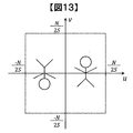
のように表せる。この条件下であれば、無限遠の物体に対して本発明の撮像装置で撮像が可能であり、これまでの議論から高速フーリエ変換(FFT)によって、図13に示すような像を得ることができる。
〈有限距離物体の撮影原理〉
ここで、これまで述べた無限遠の場合における表面側の第1の格子パターン104の裏面への射影の様子を図14に示す。無限遠の物体を構成する点1401からの球面波は、十分に長い距離を伝搬する間に平面波となり表面側の第1の格子パターン104を照射し、その投影像1402が下の面に投影される場合、投影像は第1の格子パターン104とほぼ同じ形状である。結果、投影像1402に対して、裏面側の格子パターン(図1の第2の格子パターン105に相当)の透過率分布を乗じることにより、等間隔な直線状のモアレ縞を得ることができる(図15)。It can be expressed as Under this condition, an object at infinity can be imaged by the imaging apparatus of the present invention, and an image as shown in FIG. 13 can be obtained by fast Fourier transform (FFT) based on the discussion so far. it can.
<Principle of photographing a finite distance object>
Here, FIG. 14 shows a state of projection onto the back surface of the
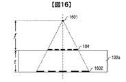
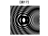
一方、有限距離の物体に対する撮像について説明する。図16は、撮像する物体が有限距離にある場合に表面側の第1の格子パターン104の裏面への射影が第1の格子パターン104より拡大されることを示す説明図である。図16に示すように、物体を構成する点1601からの球面波が表面側の第1の格子パターン104を照射し、その投影像1602が下の面に投影される場合、投影像はほぼ一様に拡大される。なお、この拡大率αは、第1の格子パターン104から点1601までの距離fを用いて、
On the other hand, imaging for a finite distance object will be described. FIG. 16 is an explanatory diagram showing that the projection onto the back surface of the
のように算出できる。 It can be calculated as follows.
そのため、平行光に対して設計された裏面側の格子パターンの透過率分布をそのまま乗じたのでは、等間隔な直線状のモアレ縞は生じなくなる(図17)。しかし、一様に拡大された表面側の第1の格子パターン104の影に合わせて、第2の格子パターン105を拡大するならば、拡大された投影像1602に対して再び、等間隔な直線状のモアレ縞を生じさせることができる(図18)。このためには、第2の格子パターン105の係数βをβ/αとすることで補正が可能である。
これにより、必ずしも無限遠でない距離の点1601からの光を選択的に再生することができる。これによって、任意の位置に焦点合わせて撮影を行うことができる。Therefore, if the transmittance distribution of the lattice pattern on the back side designed for parallel light is multiplied as it is, linear moire fringes with equal intervals do not occur (FIG. 17). However, if the second
Thereby, light from the
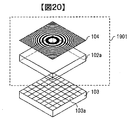
次に、変調器102の構成を簡略化する方法について説明する。変調器102では、格子基板102aの表面および裏面にそれぞれ同一形状の第1の格子パターン104および第2の格子パターン105を互いにずらして形成することにより、入射する平行光の角度をモアレ縞の空間周波数スペクトルから検知して像を構成していた。この裏面側の第2の格子パターン105は、画像センサ103に密着して入射する光の強度を変調する光学素子であり、入射光に依らず同じ格子パターンである。そこで、図19に示すように、第2の格子パターン105を除去した変調器1901を使用し、第2の格子パターン105に相当する処理を画像処理部1902内の強度変調部1903で実行してもよい。
この時の変調器1901の構成の詳細を図20に示す。この構成によって、格子基板102aに形成する格子パターンを1面減らすことができる。それにより、変調器の製造コストを低減することができる。Next, a method for simplifying the configuration of the
Details of the configuration of the
図21は、図19の画像処理部1902による画像処理の概略を示すフローチャートである。この図21におけるフローチャートが図5のフローチャートと異なるところは、ステップS2101の処理である。ステップS2101の処理では、前述した強度変調部1902により、画像センサ103から出力される画像に対して、裏面側の格子パターン105を透過したことに相当するモアレ縞画像を生成する。具体的には、式5に相当する演算が行われればよいので、強度変調部1903において裏面側の格子パターン105を生成し、画像センサ103の画像に対して乗算すればよい。さらに、裏面側の格子パターン105が図10、11に示すような2値化したパターンであれば、黒に相当する領域の画像センサ103の値を0にするだけでも実現可能である。これにより、乗算回路の規模を抑圧することが可能である。以降、図21のステップS501〜S506の処理は、図5の処理と同様であるので、ここでは説明を省略する。
FIG. 21 is a flowchart showing an outline of image processing by the
なお、この場合、画像センサ103が有する画素103aのピッチは、第1の格子パターン104のピッチを十分再現できる程度に細かいか、あるいは第1の格子パターン104のピッチが画素103aのピッチにて再現できる程度に粗い必要である。格子パターンを格子基板102aの両面に形成する場合は、必ずしも格子パターンのピッチが画像センサ103の画素103aにて解像できる必要はなく、そのモアレ像だけが解像できればよい。しかし、画像処理により格子パターンを再現する場合は、格子パターンと画像センサ103の解像度は同等である必要がある。
また、以上は強度変調部1903により第2の格子パターン105に相当する処理を実現したが、第2の格子パターン105はセンサに密着して入射する光の強度を変調する光学素子であるため、センサの感度を実効的に第2の格子パターン105の透過率を加味して設定することによっても実現できる。In this case, the pitch of the
In addition, the processing corresponding to the second
以上で説明した、裏面側の第2の格子パターン105を画像処理部で行う構成によれば、撮影後に任意の距離にフォーカスを合わせることも可能となる。この場合の構成を図22に示す。図19と異なるのは、画像記憶部2201、画像処理部2202、フォーカス設定部2203である。画像記憶部2201は、撮影後のフォーカス調整を可能とするため、画像センサ103から出力される画像を一時的に格納するために設けられている。また、フォーカス設定部2203は、撮像装置101に備え付けられたつまみや、スマートフォンのGUI(Graphical User Interface)などによってフォーカス距離を設定可能であり、フォーカス距離情報を画像処理部2202に出力する。
According to the configuration in which the
図23は、図22の画像処理部2202による画像処理の概略を示すフローチャートである。この図23におけるフローチャートが図21のフローチャートと異なるところは、ステップS2301の処理である。ステップS2301の処理では、前述したフォーカス設定部2203出力であるフォーカス距離情報に基づいて、式17から拡大率αを算出し、
裏面側の第2の格子パターン105の係数βをβ/αとする計算を行う。その後S2101において、該係数に基づいて裏面側の格子パターンを透過したことに相当するモアレ縞画像を生成する。以降、図23のステップS501〜S506の処理は、図5の処理と同様であるので、ここでは説明を省略する。FIG. 23 is a flowchart showing an outline of image processing by the
Calculation is performed by setting the coefficient β of the
以上の方法・構成に依れば、高速フーリエ変換(FFT)などの簡単な演算によって外界の物体像を得ることができ、さらに撮影後に任意の距離にフォーカスを調整可能となる。従来のカメラにおいてフォーカスを変更するためには再撮影が必要であったが、本実施例では1度の撮影しか必要としない。
なお、モアレ縞から空間周波数スペクトルを算出する方法として高速フーリエ変換を例に説明したが、これに限定されるものではなく、離散コサイン変換(DCT:Discrete Cosine Transform)などを使用しても実現可能であり、さらに演算量を削減することも可能である。According to the above method / configuration, an external object image can be obtained by a simple calculation such as fast Fourier transform (FFT), and the focus can be adjusted to an arbitrary distance after photographing. In order to change the focus in the conventional camera, re-shooting is necessary, but in this embodiment, only one shooting is required.
The fast Fourier transform has been described as an example of the method for calculating the spatial frequency spectrum from the moire fringes, but the present invention is not limited to this, and can also be realized using a discrete cosine transform (DCT) or the like. It is also possible to reduce the amount of calculation.
また、本実施例において格子パターン104,105はフレネルゾーンプレートやガボールゾーンプレートとして説明したが、これに限定されるものではなく、モアレ縞から空間周波数スペクトルを算出できさえすれば、他の実施例の1次元方向のパターンなどを使用してもよい。これらのことは他の実施例においても適用できる。
In the present embodiment, the
本実施例が実施例1と異なるのは、フォーカス調整を自動化できる点である。本実施例の構成を図24に示す。実施例1の図22と異なるのは、フォーカス位置算出部2401である。
図25は、図24のフォーカス位置算出部2401によるオートフォーカスの概略を示すフローチャートである。本オートフォーカスは、フォーカス位置を分解能Δfずつシフトさせながら現像処理し、コントラストが最大となる位置を算出することによって実現する。この処理について詳細に説明する。This embodiment is different from the first embodiment in that the focus adjustment can be automated. The configuration of this example is shown in FIG. What is different from FIG. 22 of the first embodiment is a focus
FIG. 25 is a flowchart showing an outline of autofocus by the focus
まず、フォーカス位置の初期値(無限遠もしくは距離0など)を設定(S2501)、フォーカス位置から拡大率αを算出し、第2の格子パターン105の係数βを算出する(S2301)。S2101からS503までは図23と同様であり、その後、図26に示すように撮像範囲内の領域2601内の任意の領域2601aを切り出す(S2503)。この領域がフォーカス調整に用いる領域であり、ユーザがGUIで設定するか、顔認識技術等により自動的に設定してもよい。次に、領域2601a内のコントラストを、領域内の最大輝度Imax、最小輝度Iminを用いて、
First, an initial value (such as infinity or distance 0) of the focus position is set (S2501), an enlargement factor α is calculated from the focus position, and a coefficient β of the
により算出(S2504)、結果をメモリに格納する(S2505)。 (S2504) and the result is stored in the memory (S2505).
この後、フォーカス位置をΔfずらして設定(S2502)、以降のS2502からS2505までの処理を予め設定したフォーカス可変範囲内の走査が完了するまで実施する(S2506)。探索完了後、メモリ内のコントラスト情報を読み出すと、図27に示したように、コントラストとフォーカス位置の関係が得られるので(S2507)、コントラストが最大となるフォーカス位置を探索し(S2508)、出力する(S2509)。
このフォーカス位置算出部2401において得られたフォーカス位置情報に基づき、画像処理部2202で画像処理を行えば、最適なフォーカスでの撮影が可能となる。Thereafter, the focus position is set by being shifted by Δf (S2502), and the subsequent processing from S2502 to S2505 is carried out until scanning within the preset focus variable range is completed (S2506). When the contrast information in the memory is read after completion of the search, as shown in FIG. 27, the relationship between the contrast and the focus position is obtained (S2507). Therefore, the focus position at which the contrast is maximized is searched (S2508) and output. (S2509).
If image processing is performed by the
以上の方法・構成に依れば、フォーカス調整を自動化でき、さらに従来のカメラと異なり、再撮影を行うことなく最適なフォーカスでの撮影が可能となる。 According to the above method and configuration, focus adjustment can be automated, and unlike conventional cameras, it is possible to shoot with an optimum focus without performing re-shooting.
なお、本実施例においてコントラストが最大となる探索を行ったが、これに限定するものではなく、SNR(Signal to Noise Ratio)や、HPF(High−Pass Filter)結果の加算値など、鮮明な画像となるフォーカス位置を決定できる方法であればよい。
また、フォーカス位置の走査範囲はユーザが予め設定することも可能である。
また、フォーカス位置をΔfずつシフトする方法について説明したが、これに限定するものではない。フォーカス位置が変わることによる像のボケ方は、遠方ほど位置に対する感度が低くなるため、撮像装置101近傍は細かく、遠方は粗くシフトさせることでより高精度・高速な探索が可能となる。
これらのことは他の実施例においても適用できる。In this embodiment, the search with the maximum contrast is performed. However, the present invention is not limited to this, and a clear image such as an SNR (Signal to Noise Ratio) or an addition value of an HPF (High-Pass Filter) result is obtained. Any method can be used as long as the focus position can be determined.
Further, the scanning range of the focus position can be set in advance by the user.
Further, although the method of shifting the focus position by Δf has been described, the present invention is not limited to this. The image blur due to the change of the focus position is less sensitive to the position as it is farther, so that the vicinity of the
These can be applied to other embodiments.
本実施例が実施例1と異なるのは、画像のみならず2次元方向(水平ならびに垂直方向)の距離情報を取得できる点である。本実施例の構成を図28に示す。実施例1の図22と異なるのは、距離計測部2801ならびに距離情報表示部2802である。
図29は、図28の距離計測部2801による距離計測の概略を示すフローチャートである。本距離計測は、実施例2のオートフォーカスの原理を領域毎に実施することで、最適なフォーカス位置(=物体が存在する位置)を計測することによって実現する。この処理について詳細に説明する。This embodiment is different from the first embodiment in that it can acquire not only an image but also distance information in a two-dimensional direction (horizontal and vertical directions). The configuration of this example is shown in FIG. A difference from FIG. 22 of the first embodiment is a
FIG. 29 is a flowchart showing an outline of distance measurement by the
まず、S2501からS503までは実施例2の図25と同様である。その後、図30に示すように撮像範囲内の領域2601を分割する(S2901)。この分割サイズが距離計測における2次元方向の分解能に対応するためサイズが細かい方が好ましいが、細かくし過ぎると測定誤差が増大する問題がある。よって、環境に応じてユーザが分割サイズを変更できることも有用である。この分割した領域3001の例として領域3001aと3001bを図30に示している。次に、領域毎に領域内のコントラストを、領域内の最大輝度Imax、最小輝度Iminを用いて、
First, S2501 to S503 are the same as those in FIG. 25 of the second embodiment. Thereafter, as shown in FIG. 30, an
により算出(S2902)、結果をメモリに格納する(S2903)。 (S2902) and the result is stored in the memory (S2903).
この後、フォーカス位置をΔfずらして設定(S2502)、以降のS2502からS2903までの処理を予め設定したフォーカス可変範囲内の走査が完了するまで実施する(S2904)。探索完了後、メモリ内のコントラスト情報を読み出すと、図31に示したように、コントラストとフォーカス位置の関係が得られる(S2905)。この例のように、遠方の山が領域内に含まれる領域3001aは遠方でコントラストが最大となり、近傍の人が領域内に含まれる領域3001bは比較的近傍でコントラストが最大となっている様子が判る。例では2つの領域の変化のみ図31に示しているが、実際には図30における領域3001の分割数の数だけメモリに格納されていることになる。このように、領域毎にコントラストが最大となるフォーカス位置を探索し(S2906)、距離情報の2次元マップを作成し出力する(S2907)。
Thereafter, the focus position is set by being shifted by Δf (S2502), and the subsequent processes from S2502 to S2903 are performed until scanning within the preset focus variable range is completed (S2904). When the contrast information in the memory is read after the search is completed, the relationship between the contrast and the focus position is obtained as shown in FIG. 31 (S2905). As in this example, the
この距離情報を距離情報表示部2802により表示することで、2次元方向の距離情報を確認可能となる。ここでは、距離情報表示部2802を使用したが、距離計測部2801出力を直接用いることにより、自動車やドローンのような機器における、障害物認識、自動運転に適用することもできる。
By displaying this distance information by the distance
以上の方法・構成に依れば、画像のみならず2次元方向(水平ならびに垂直方向)の距離情報を取得することが可能となる。 According to the above method and configuration, it is possible to acquire not only an image but also distance information in a two-dimensional direction (horizontal and vertical directions).
なお、本実施例においてコントラストが最大となる探索を行ったが、これに限定するものではなく、SNR(Signal to Noise Ratio)や、HPF(High−Pass Filter)結果の加算値など、鮮明な画像となるフォーカス位置を決定できる方法であればよい。
また、2次元の距離測定が不要な場合、図32に示すように撮像範囲内の領域2601を横方向に分割し、分割領域3001単位で距離測定することもできる。これにより、水平方向のみの距離測定しか行えないが、縦方向の情報を使うことにより距離情報のSNRを向上可能である。もちろん、撮像範囲内の領域2601の分割を縦方向に行うことにより、垂直方向のみの距離測定とすることも可能である。In this embodiment, the search with the maximum contrast is performed. However, the present invention is not limited to this, and a clear image such as an SNR (Signal to Noise Ratio) or an addition value of an HPF (High-Pass Filter) result is obtained. Any method can be used as long as the focus position can be determined.
In addition, when two-dimensional distance measurement is unnecessary, an
また、本実施例では単一フレームから距離情報を算出する例について述べたが、複数フレームの画像を平均化して使用する、または複数フレームの距離情報を平均化して使用することによってSNRを向上し、距離精度を向上したり、2次元方向の分解能を向上したりすることが可能である。 In this embodiment, an example in which distance information is calculated from a single frame has been described. However, the SNR is improved by averaging and using images of a plurality of frames, or averaging and using distance information of a plurality of frames. The distance accuracy can be improved and the resolution in the two-dimensional direction can be improved.
また、フレーム間での距離情報の差分を求めることによって、2次元方向または1次元方向の速度情報を算出することも可能である。
これらのことは他の実施例においても適用できる。It is also possible to calculate speed information in a two-dimensional direction or a one-dimensional direction by obtaining a difference in distance information between frames.
These can be applied to other embodiments.
実施例3では図32の例のように1次元方向の測距を行う際にも、図28のように2次元の画像センサ103を使用していることから、図29のS501を2次元フーリエ変換により行わなければならず、計算コスト、画像センサコストが増大することになる。
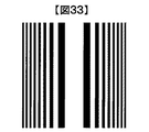
そこで、本実施例では1次元方向の測距に特化した構成について説明する。本実施例の構成は実施例3における図28と同一でよいが、変調器1901の第1の格子パターン104を図33に示すように1次元方向のパターンとする。このパターンにおける複数の直線は、基準座標に対して直線間距離が反比例して狭くなっている。このパターンは、In the third embodiment, since the two-
In this embodiment, a configuration specialized for distance measurement in the one-dimensional direction will be described. Although the configuration of the present embodiment may be the same as that of FIG. 28 in the third embodiment, the first
により定義できる。このように、垂直方向に同一パターンが連続する格子パターンを使用することによって、水平方向にのみの検出を可能とする。 Can be defined. In this way, detection using only the horizontal direction is possible by using a lattice pattern in which the same pattern continues in the vertical direction.
この格子パターンを用いた例を図34に示す。変調器3401とラインセンサ3402から構成されている。また、変調器3401の表面は式20に基づく格子パターン3403により透過率が変調されている。本構成に依れば、1次元のラインセンサを用いることでセンサコストを抑圧し、さらにフーリエ変換を1次元フーリエ変換とすることで演算量を大幅に低減することが可能である。なお、この例ではセンサ側(裏面)の格子パターンを省略した構成を示しているが、もちろん裏面の格子パターンがある構成で実現してもよく、このことは全ての議論でも同様である。
An example using this lattice pattern is shown in FIG. A
別の例を図35に示す。シリンドリカルレンズ3501、変調器3502、ラインセンサ3402から構成されている。また、変調器3502の表面は式20に基づく格子パターン3503により透過率が変調されている。さらに、シリンドリカルレンズ3501の焦点位置がラインセンサ3402上となるように配置されている。本構成に依れば、図34よりも多くの光を用いて検出することができるため、距離情報のSNRを向上することが可能である。
Another example is shown in FIG. It consists of a
さらに別の例を図36に示す。変調器3502、画像センサ103、垂直方向加算部3601から構成されている。垂直方向加算部3601では、画像センサ103垂直方向の輝度を加算する演算を行う。本構成に依れば、図35のようにシリンドリカルレンズ3501を用いなくても、よりも多くの光を用いて検出することができるため、距離情報のSNRを向上することが可能である。
Yet another example is shown in FIG. It comprises a
なお、本実施例では図33の1次元方向のパターンを測距に使用する例について述べたが、他の実施例の格子パターン104,105として使用することで、1次元方向に限定した撮影、リフォーカス、オートフォーカスなどの処理が可能であり、周波数スペクトルに必要な演算量を大幅に低減することが可能である。
In the present embodiment, the example in which the pattern in the one-dimensional direction of FIG. 33 is used for distance measurement has been described. However, by using it as the
また、以上の例では水平方向の測距に特化した構成について説明したが、これに限定するものではなく、図33に示した格子パターンを、 In the above example, the configuration specialized for horizontal distance measurement has been described. However, the configuration is not limited to this, and the lattice pattern shown in FIG.
のように、水平方向に同一パターンが連続する格子パターンを使用することによって、垂直方向にのみの検出を可能としたり、任意の角度方向の検出を行ったりすることも可能である。
これらのことは他の実施例においても適用できる。As described above, by using a lattice pattern in which the same pattern continues in the horizontal direction, it is possible to detect only in the vertical direction or to detect in an arbitrary angle direction.
These can be applied to other embodiments.
これまでの実施例では、画像処理部2002や距離計測部2201などの演算のため、撮像装置101サイズが大きくなってしまう可能性がある。そこで、本実施例では撮像装置101サイズを小さくするための処理分割方法について説明する。
In the embodiments so far, there is a possibility that the size of the
本実施例の構成を図37に示す。実施例3の図28と異なり、撮像装置101に含まれるのは主に変調器1901、画像センサ103であり、信号処理部3701に画像記憶部2201、画像処理部2202、距離計測部2801が含まれている。
本構成において、撮像装置101出力を有線もしくは無線LAN(Local Area Network)を介してインターネットに接続するなどすれば、信号処理部3701はサーバなどで行っても良く、撮像装置101の大きさを制限することが無くなる。
しかし、図37の構成では画像センサ103出力のデータ容量が大きいことが問題になると考えられる。そこで、実施例2などのように、フォーカス位置が決まっている場合に画像を圧縮する方法について図38で説明する。The configuration of this embodiment is shown in FIG. Unlike FIG. 28 of the third embodiment, the
In this configuration, if the output of the
However, in the configuration of FIG. 37, it can be considered that the data capacity of the output of the
図38は、実施例2の図22と異なり、撮像装置101に含まれるのは主に変調器1901、画像センサ103、画像圧縮部3801、フォーカス設定部2203であり、信号処理部3802に画像処理部106が含まれている。
In FIG. 38, unlike FIG. 22 of the second embodiment, the
図39は、図38の画像圧縮部3801による画像圧縮の概略を示すフローチャートである。フォーカス設定部2203出力であるフォーカス距離情報に基づいて、式17から拡大率αを算出し、裏面側の第2の格子パターン105の係数βをβ/αとする計算を行う(S3901)。その後、該係数に基づいて裏面側の格子パターンを透過したことに相当するモアレ縞画像を生成する(S3902)。ここで、画像センサ103が有する画素103aのピッチは、第1の格子パターン104のピッチを十分再現できる程度に細かいためにデータ容量が増大している。よって、モアレ像が解像できるだけの空間周波数を通過するLPF(Low−Pass Filter)を作用させた後に(S3903)、ダウンサンプリングを行い(S3904)、データ容量を圧縮する。なお、このダウンサンプルの際のサンプリング周波数がLPF通過帯域の倍以上であればサンプリング定理上元の信号を復元することが可能であるため望ましいが、限定するものではない。
FIG. 39 is a flowchart showing an outline of image compression by the
なお、本発明は上記の実施例に限定されるものではなく、様々な変形例が含まれる。例えば、上記した実施例は本発明を分かりやすく説明するために詳細に説明したものであり、必ずしも説明した全ての構成を備えるものに限定されるものではない。
また、ある実施例の構成の一部を他の実施例の構成に置き換えることが可能であり、また、ある実施例の構成に他の実施例の構成を加えることも可能である。In addition, this invention is not limited to said Example, Various modifications are included. For example, the above-described embodiments have been described in detail for easy understanding of the present invention, and are not necessarily limited to those having all the configurations described.
Further, a part of the configuration of one embodiment can be replaced with the configuration of another embodiment, and the configuration of another embodiment can be added to the configuration of one embodiment.
また、各実施例の構成の一部について、他の構成の追加・削除・置換をすることが可能である。
また、上記の各構成、機能、処理部、処理手段等は、それらの一部又は全部を、例えば集積回路で設計する等によりハードウェアで実現してもよい。また、上記の各構成、機能等は、プロセッサがそれぞれの機能を実現するプログラムを解釈し、実行することによりソフトウェアで実現してもよい。各機能を実現するプログラム、テーブル、ファイル等の情報は、メモリや、ハードディスク、SSD(Solid State Drive)等の記録装置、または、ICカード、SDカード、DVD等の記録媒体に置くことができる。
また、制御線や情報線は説明上必要と考えられるものを示しており、製品上必ずしも全ての制御線や情報線を示しているとは限らない。実際には殆ど全ての構成が相互に接続されていると考えてもよい。Further, it is possible to add, delete, and replace other configurations for a part of the configuration of each embodiment.
Each of the above-described configurations, functions, processing units, processing means, and the like may be realized by hardware by designing a part or all of them with, for example, an integrated circuit. Each of the above-described configurations, functions, and the like may be realized by software by interpreting and executing a program that realizes each function by the processor. Information such as programs, tables, and files for realizing each function can be stored in a memory, a hard disk, a recording device such as an SSD (Solid State Drive), or a recording medium such as an IC card, an SD card, or a DVD.
Further, the control lines and information lines indicate what is considered necessary for the explanation, and not all the control lines and information lines on the product are necessarily shown. Actually, it may be considered that almost all the components are connected to each other.
101・・・撮像装置、102・・・変調器、102a・・・格子基板、102b・・・支持部材、103・・・画像センサ、103a・・・画素、106・・・画像処理部、107・・・画像表示部、104・・・格子パターン(表側)、105・・・格子パターン(裏側)、401・・・被写体、1201・・・格子センサ一体基板、1401・・・点、1402・・・投影像、1601・・・点、1602・・・投影像、1901・・・変調器、1902・・・画像処理部、1903・・・強度変調部、2201・・・画像記憶部、2202・・・画像処理部、2203・・・フォーカス設定部、2401・・・フォーカス位置算出部、2601・・・領域、2601a・・・領域、2801・・・距離計測部、2802・・・距離情報表示部、3001・・・領域、3001a・・・領域、3001b・・・領域、3201・・・領域、3401・・・変調器、3402・・・ラインセンサ、3403・・・格子パターン、3501・・・シリンドリカルレンズ、3502・・・変調器、3503・・・格子パターン、3601・・・垂直方向加算部、3701・・・信号処理部、3801・・・画像圧縮部、3802・・・信号処理
DESCRIPTION OF
Claims (14)
前記画像センサの受光面に設けられ、光の強度を変調する変調器と、
前記画像センサから出力される画像信号を一時的に格納する画像記憶部と、
前記画像記憶部から出力される画像信号の画像処理を行う信号処理部と、
を具備し、
前記変調器は、複数の同心円から構成される第1の格子パターンを有し、
前記信号処理部は、前記画像記憶部から出力される画像信号を、複数の同心円から構成される仮想的な第2の格子パターンで変調することでモアレ縞画像を生成し、フォーカス位置に応じて前記第2の格子パターンの同心円の大きさを変更することを特徴とする撮像装置。 An image sensor that converts an optical image captured by a plurality of pixels arranged in an array on the imaging surface into an image signal and outputs the image signal;
A modulator provided on the light receiving surface of the image sensor for modulating the intensity of light;
An image storage unit for temporarily storing an image signal output from the image sensor;
A signal processing unit that performs image processing of an image signal output from the image storage unit;
Comprising
The modulator has a first grating pattern composed of a plurality of concentric circles,
The signal processing unit generates a moire fringe image by modulating the image signal output from the image storage unit with a virtual second lattice pattern composed of a plurality of concentric circles, and generates a moire fringe image according to the focus position. An imaging apparatus, wherein a size of a concentric circle of the second lattice pattern is changed.
適切なフォーカス位置を推定するフォーカス位置算出部を具備し、
前記フォーカス位置算出部は、フォーカス位置を変化させながら、モアレ縞画像に基づいて得られる画像の評価指標を算出し、前記評価指標のピークを検出することにより適切なフォーカス位置を推定することを特徴とする撮像装置。 The imaging device according to claim 1,
A focus position calculator for estimating an appropriate focus position;
The focus position calculation unit calculates an evaluation index of an image obtained based on a moire fringe image while changing the focus position, and estimates an appropriate focus position by detecting a peak of the evaluation index. An imaging device.
前記信号処理部は、フォーカス位置を変化させながら、モアレ縞画像に基づいて得られる画像の評価指標を分割した領域毎に算出し、前記領域毎に前記評価指標のピークを検出することにより前記領域毎に被写体までの距離を推定することを特徴とする撮像装置。 The imaging device according to claim 1,
The signal processing unit calculates, for each divided area, an evaluation index of an image obtained based on a moire fringe image while changing a focus position, and detects the peak of the evaluation index for each of the areas. An imaging apparatus characterized by estimating a distance to a subject for each time.
前記領域は、撮影範囲の水平方向にのみ分割されていることを特徴とする撮像装置。 The imaging device according to claim 3.
The imaging apparatus according to claim 1, wherein the area is divided only in a horizontal direction of an imaging range.
前記領域は、撮影範囲の垂直方向にのみ分割されていることを特徴とする撮像装置。 The imaging device according to claim 3.
The image pickup apparatus according to claim 1, wherein the area is divided only in a direction perpendicular to a shooting range.
前記第1の格子パターン及び前記第2の格子パターンにおける前記複数の同心円は、同心円の中心となる基準座標に対して同心円のピッチが反比例して細かくなることを特徴とする撮像装置。 The imaging device according to any one of claims 1 to 5,
The imaging apparatus according to claim 1, wherein the concentric circles in the first lattice pattern and the second lattice pattern have a fine pitch in inverse proportion to a reference coordinate that is the center of the concentric circle.
前記信号処理部は、生成した前記モアレ縞画像を2次元フーリエ変換して周波数スペクトルを算出することを特徴とする撮像装置。 The imaging device according to any one of claims 1 to 5,
The signal processing unit calculates a frequency spectrum by performing two-dimensional Fourier transform on the generated moire fringe image.
前記画像センサの受光面に設けられ、光の強度を変調する変調器と、
前記画像センサから出力される画像信号を一時的に格納する画像記憶部と、
前記画像記憶部から出力される画像信号の画像処理を行う信号処理部と、
を具備し、
前記変調器は、複数の直線から構成される第1の格子パターンを有し、
前記信号処理部は、前記画像記憶部から出力される画像信号を、複数の直線から構成される仮想的な第2の格子パターンで変調することでモアレ縞画像を生成し、
前記信号処理部は、フォーカス位置に応じて前記第2の格子パターンの直線間距離を変更することを特徴とする撮像装置。 An image sensor that converts an optical image captured by a plurality of pixels arranged in an array on the imaging surface into an image signal and outputs the image signal;
A modulator provided on the light receiving surface of the image sensor for modulating the intensity of light;
An image storage unit for temporarily storing an image signal output from the image sensor;
A signal processing unit that performs image processing of an image signal output from the image storage unit;
Comprising
The modulator has a first lattice pattern composed of a plurality of straight lines,
The signal processing unit generates a moire fringe image by modulating the image signal output from the image storage unit with a virtual second lattice pattern composed of a plurality of straight lines,
The image processing apparatus, wherein the signal processing unit changes a distance between straight lines of the second lattice pattern according to a focus position.
適切なフォーカス位置を推定するフォーカス位置算出部を具備し、
前記フォーカス位置算出部は、フォーカス位置を変化させながら、モアレ縞画像に基づいて得られる画像の評価指標を算出し、前記評価指標のピークを検出することにより適切なフォーカス位置を推定することを特徴とする撮像装置。 The imaging device according to claim 8,
A focus position calculator for estimating an appropriate focus position;
The focus position calculation unit calculates an evaluation index of an image obtained based on a moire fringe image while changing the focus position, and estimates an appropriate focus position by detecting a peak of the evaluation index. An imaging device.
被写体までの距離を推定する距離計測部を具備し、
前記距離計測部は、フォーカス位置を変化させながら、モアレ縞画像に基づいて得られる画像の評価指標を分割した領域毎に算出し、前記複数の領域毎に前記評価指標のピークを検出することにより複数の領域毎に被写体までの距離を推定することを特徴とする撮像装置。 The imaging device according to claim 8,
It has a distance measurement unit that estimates the distance to the subject,
The distance measuring unit calculates the evaluation index of the image obtained based on the moire fringe image while changing the focus position for each divided area, and detects the peak of the evaluation index for each of the plurality of areas. An imaging apparatus that estimates a distance to a subject for each of a plurality of regions.
前記第1の格子パターン及び前記第2の格子パターンにおける前記複数の直線は、基準座標に対して直線間距離が反比例して狭くなることを特徴とする撮像装置。 The imaging device according to any one of claims 8 to 10,
The imaging apparatus according to claim 1, wherein a distance between the straight lines of the plurality of straight lines in the first grid pattern and the second grid pattern becomes narrower in inverse proportion to a reference coordinate.
前記信号処理部は、生成した前記モアレ縞画像を1次元フーリエ変換して周波数スペクトルを算出することを特徴とする撮像装置。 The imaging device according to any one of claims 8 to 10,
The signal processing unit calculates a frequency spectrum by performing a one-dimensional Fourier transform on the generated moire fringe image.
前記画像センサの受光面に設けられ、光の強度を変調する変調器と、
前記画像センサから出力される画像信号の画像処理を行う信号処理部と、
を具備し、
前記変調器は、複数の直線から構成される第1の格子パターンと第2の格子パターンを有し、
前記変調器は、前記第1の格子パターンを透過する光を前記第2の格子パターンにて強度変調することでモアレ縞画像を生成するものであって、
前記第1の格子パターン及び前記第2の格子パターンにおける前記複数の直線は、基準座標に対して直線間距離が反比例して狭くなることを特徴とする撮像装置。 An image sensor that converts an optical image captured by a plurality of pixels arranged in an array on the imaging surface into an image signal and outputs the image signal;
A modulator provided on the light receiving surface of the image sensor for modulating the intensity of light;
A signal processing unit that performs image processing of an image signal output from the image sensor ;
Comprising
The modulator has a first grating pattern and a second grating pattern composed of a plurality of straight lines,
The modulator generates a moire fringe image by intensity-modulating light transmitted through the first grating pattern with the second grating pattern ,
The imaging apparatus according to claim 1, wherein a distance between the straight lines of the plurality of straight lines in the first grid pattern and the second grid pattern becomes narrower in inverse proportion to a reference coordinate .
前記信号処理部は、前記画像信号を1次元フーリエ変換して周波数スペクトルを算出することを特徴とする撮像装置。 The imaging device according to claim 13.
The image processing apparatus, wherein the signal processing unit calculates a frequency spectrum by performing a one-dimensional Fourier transform on the image signal .
Applications Claiming Priority (1)
| Application Number | Priority Date | Filing Date | Title |
|---|---|---|---|
| PCT/JP2016/056323 WO2017149687A1 (en) | 2016-03-02 | 2016-03-02 | Imaging device |
Publications (2)
| Publication Number | Publication Date |
|---|---|
| JPWO2017149687A1 JPWO2017149687A1 (en) | 2018-10-11 |
| JP6571266B2 true JP6571266B2 (en) | 2019-09-04 |
Family
ID=59743613
Family Applications (1)
| Application Number | Title | Priority Date | Filing Date |
|---|---|---|---|
| JP2018502932A Active JP6571266B2 (en) | 2016-03-02 | 2016-03-02 | Imaging device |
Country Status (4)
| Country | Link |
|---|---|
| US (1) | US10670829B2 (en) |
| JP (1) | JP6571266B2 (en) |
| CN (1) | CN108370406B (en) |
| WO (1) | WO2017149687A1 (en) |
Families Citing this family (22)
| Publication number | Priority date | Publication date | Assignee | Title |
|---|---|---|---|---|
| JP6688716B2 (en) * | 2016-10-04 | 2020-04-28 | 株式会社日立製作所 | Imaging device and imaging method |
| CN109670389B (en) * | 2017-10-16 | 2023-04-07 | 富士通株式会社 | Method and equipment for evaluating illumination condition in face image |
| EP3700187B1 (en) * | 2017-10-19 | 2023-04-12 | Sony Group Corporation | Signal processing device and imaging device |
| CN111201778B (en) * | 2017-10-19 | 2022-02-08 | 索尼公司 | Imaging apparatus, exposure control method, computer-readable storage medium, and imaging device |
| JP6920974B2 (en) | 2017-12-11 | 2021-08-18 | 株式会社日立製作所 | Distance measuring device and distance measuring method |
| JP2021043230A (en) * | 2017-12-26 | 2021-03-18 | 富士フイルム株式会社 | Wide-conversion lens and imaging apparatus |
| CN111527737B (en) * | 2017-12-26 | 2022-03-25 | 富士胶片株式会社 | Image pickup apparatus |
| JP2019149674A (en) | 2018-02-27 | 2019-09-05 | 株式会社日立製作所 | Imaging apparatus, imaging method, and image processing apparatus |
| JP6814762B2 (en) * | 2018-03-16 | 2021-01-20 | 株式会社日立製作所 | Imaging device |
| JP7076246B2 (en) | 2018-03-23 | 2022-05-27 | マクセル株式会社 | Imaging equipment and imaging system |
| US11470247B2 (en) | 2018-03-29 | 2022-10-11 | Sony Corporation | Information processing device, information processing method, program, and information processing system |
| WO2020031299A1 (en) | 2018-08-08 | 2020-02-13 | マクセル株式会社 | Imaging device, imaging system, and imaging method |
| JP7112504B2 (en) | 2018-09-18 | 2022-08-03 | マクセル株式会社 | Distance measuring device, imaging device, distance measuring system, distance measuring method, and imaging method |
| CN109858471A (en) * | 2019-04-03 | 2019-06-07 | 深圳市华付信息技术有限公司 | Biopsy method, device and computer equipment based on picture quality |
| CN114008615A (en) * | 2019-06-28 | 2022-02-01 | 麦克赛尔株式会社 | 3D authentication device, 3D authentication system, portable information terminal, and 3D authentication method |
| JP7341239B2 (en) * | 2019-07-31 | 2023-09-08 | マクセル株式会社 | Imaging device, mobile terminal, and exposure control method |
| CN114208145A (en) | 2019-08-08 | 2022-03-18 | 麦克赛尔株式会社 | Image pickup apparatus and method |
| US20230111094A1 (en) * | 2020-03-27 | 2023-04-13 | Sony Group Corporation | Microscope system, imaging method, and imaging device |
| JP2021173874A (en) | 2020-04-24 | 2021-11-01 | Hoya株式会社 | Optical element and optical device |
| WO2022113365A1 (en) * | 2020-11-30 | 2022-06-02 | 株式会社ニコン | Focusing method, observation device, and program |
| CN113409417B (en) * | 2021-07-15 | 2023-05-30 | 南京信息工程大学 | Moire fringe information extraction method based on wavelet transformation |
| CN115790452B (en) * | 2023-02-06 | 2023-05-16 | 西安知象光电科技有限公司 | Gear tooth surface three-dimensional morphology moire characterization and measurement method |
Family Cites Families (11)
| Publication number | Priority date | Publication date | Assignee | Title |
|---|---|---|---|---|
| CA2390072C (en) * | 2002-06-28 | 2018-02-27 | Adrian Gh Podoleanu | Optical mapping apparatus with adjustable depth resolution and multiple functionality |
| CN101995594A (en) | 2005-08-29 | 2011-03-30 | 松下电器产业株式会社 | Diffractive optical element and method for manufacturing the same, and imaging apparatus using the diffractive optical element |
| US8106993B2 (en) | 2006-05-15 | 2012-01-31 | Panasonic Corporation | Diffractive imaging lens, diffractive imaging lens optical system, and imaging apparatus using the diffractive imaging lens optical system |
| JP2009055479A (en) * | 2007-08-28 | 2009-03-12 | Panasonic Corp | Image sensor and electromagnetic wave imaging apparatus |
| JP5725874B2 (en) * | 2011-01-14 | 2015-05-27 | キヤノン株式会社 | Shearing interference measuring apparatus and calibration method thereof |
| US9402067B2 (en) * | 2012-10-22 | 2016-07-26 | Samsung Electronics Co., Ltd. | Imaging optical system for 3D image acquisition apparatus, and 3D image acquisition apparatus including the imaging optical system |
| US9110240B2 (en) | 2013-03-05 | 2015-08-18 | Rambus Inc. | Phase gratings with odd symmetry for high-resolution lensed and lensless optical sensing |
| US9746593B2 (en) * | 2013-08-28 | 2017-08-29 | Rambus Inc. | Patchwork Fresnel zone plates for lensless imaging |
| JP2015115527A (en) * | 2013-12-13 | 2015-06-22 | 株式会社東芝 | Solid state image pickup device and camera system |
| CN104006765B (en) | 2014-03-14 | 2016-07-13 | 中国科学院上海光学精密机械研究所 | Single width carrier frequency interference fringe phase extraction method and detecting device |
| JP6491332B2 (en) * | 2015-06-17 | 2019-03-27 | マクセル株式会社 | Imaging device |
-
2016
- 2016-03-02 JP JP2018502932A patent/JP6571266B2/en active Active
- 2016-03-02 CN CN201680070424.2A patent/CN108370406B/en active Active
- 2016-03-02 US US16/070,355 patent/US10670829B2/en active Active
- 2016-03-02 WO PCT/JP2016/056323 patent/WO2017149687A1/en active Application Filing
Also Published As
| Publication number | Publication date |
|---|---|
| JPWO2017149687A1 (en) | 2018-10-11 |
| CN108370406A (en) | 2018-08-03 |
| US10670829B2 (en) | 2020-06-02 |
| US20190339485A1 (en) | 2019-11-07 |
| CN108370406B (en) | 2020-11-10 |
| WO2017149687A1 (en) | 2017-09-08 |
Similar Documents
| Publication | Publication Date | Title |
|---|---|---|
| JP6571266B2 (en) | Imaging device | |
| JP6491332B2 (en) | Imaging device | |
| Jeon et al. | Accurate depth map estimation from a lenslet light field camera | |
| JP3481631B2 (en) | Apparatus and method for determining a three-dimensional shape of an object using relative blur in an image due to active illumination and defocus | |
| US10461108B2 (en) | Imaging device | |
| CN109804616B (en) | Image pickup apparatus | |
| CN107896292B (en) | Image pickup apparatus and image pickup method | |
| WO2017145348A1 (en) | Imaging device | |
| US10488561B2 (en) | Imaging device | |
| US10887504B2 (en) | Distance measurement device and distance measurement method | |
| JP6646619B2 (en) | Imaging device | |
| JP6807281B2 (en) | Imaging device, imaging system, and imaging method | |
| JP7097787B2 (en) | Imaging device and imaging method | |
| JP6947891B2 (en) | Mobile information terminal | |
| JP6770164B2 (en) | Imaging device | |
| JP7183429B2 (en) | Imaging device and method | |
| JP4091455B2 (en) | Three-dimensional shape measuring method, three-dimensional shape measuring apparatus, processing program therefor, and recording medium | |
| JP2000121335A (en) | Moire measurement method and moire measurement device using it | |
| JP7389195B2 (en) | Image generation method | |
| JP6636663B2 (en) | Imaging device and image generation method | |
| JP7159118B2 (en) | Imaging device | |
| JP7065761B2 (en) | Distance measuring device and distance measuring method | |
| CN110278350B (en) | Image pickup apparatus |
Legal Events
| Date | Code | Title | Description |
|---|---|---|---|
| A521 | Request for written amendment filed |
Free format text: JAPANESE INTERMEDIATE CODE: A523 Effective date: 20180531 |
|
| A621 | Written request for application examination |
Free format text: JAPANESE INTERMEDIATE CODE: A621 Effective date: 20180531 |
|
| TRDD | Decision of grant or rejection written | ||
| A01 | Written decision to grant a patent or to grant a registration (utility model) |
Free format text: JAPANESE INTERMEDIATE CODE: A01 Effective date: 20190716 |
|
| A61 | First payment of annual fees (during grant procedure) |
Free format text: JAPANESE INTERMEDIATE CODE: A61 Effective date: 20190807 |
|
| R150 | Certificate of patent or registration of utility model |
Ref document number: 6571266 Country of ref document: JP Free format text: JAPANESE INTERMEDIATE CODE: R150 |