JP6570534B2 - In-situ suture joint forming method and apparatus - Google Patents
In-situ suture joint forming method and apparatus Download PDFInfo
- Publication number
- JP6570534B2 JP6570534B2 JP2016551765A JP2016551765A JP6570534B2 JP 6570534 B2 JP6570534 B2 JP 6570534B2 JP 2016551765 A JP2016551765 A JP 2016551765A JP 2016551765 A JP2016551765 A JP 2016551765A JP 6570534 B2 JP6570534 B2 JP 6570534B2
- Authority
- JP
- Japan
- Prior art keywords
- suture
- shaft
- intermediate shaft
- sleeve
- distal end
- Prior art date
- Legal status (The legal status is an assumption and is not a legal conclusion. Google has not performed a legal analysis and makes no representation as to the accuracy of the status listed.)
- Expired - Fee Related
Links
Images


Classifications
-
- A—HUMAN NECESSITIES
- A61—MEDICAL OR VETERINARY SCIENCE; HYGIENE
- A61B—DIAGNOSIS; SURGERY; IDENTIFICATION
- A61B17/00—Surgical instruments, devices or methods, e.g. tourniquets
- A61B17/04—Surgical instruments, devices or methods, e.g. tourniquets for suturing wounds; Holders or packages for needles or suture materials
- A61B17/0401—Suture anchors, buttons or pledgets, i.e. means for attaching sutures to bone, cartilage or soft tissue; Instruments for applying or removing suture anchors
-
- A—HUMAN NECESSITIES
- A61—MEDICAL OR VETERINARY SCIENCE; HYGIENE
- A61B—DIAGNOSIS; SURGERY; IDENTIFICATION
- A61B17/00—Surgical instruments, devices or methods, e.g. tourniquets
- A61B17/04—Surgical instruments, devices or methods, e.g. tourniquets for suturing wounds; Holders or packages for needles or suture materials
- A61B17/0467—Instruments for cutting sutures
-
- A—HUMAN NECESSITIES
- A61—MEDICAL OR VETERINARY SCIENCE; HYGIENE
- A61B—DIAGNOSIS; SURGERY; IDENTIFICATION
- A61B17/00—Surgical instruments, devices or methods, e.g. tourniquets
- A61B17/04—Surgical instruments, devices or methods, e.g. tourniquets for suturing wounds; Holders or packages for needles or suture materials
- A61B17/0487—Suture clamps, clips or locks, e.g. for replacing suture knots; Instruments for applying or removing suture clamps, clips or locks
-
- A—HUMAN NECESSITIES
- A61—MEDICAL OR VETERINARY SCIENCE; HYGIENE
- A61B—DIAGNOSIS; SURGERY; IDENTIFICATION
- A61B17/00—Surgical instruments, devices or methods, e.g. tourniquets
- A61B2017/00831—Material properties
- A61B2017/00862—Material properties elastic or resilient
-
- A—HUMAN NECESSITIES
- A61—MEDICAL OR VETERINARY SCIENCE; HYGIENE
- A61B—DIAGNOSIS; SURGERY; IDENTIFICATION
- A61B17/00—Surgical instruments, devices or methods, e.g. tourniquets
- A61B17/04—Surgical instruments, devices or methods, e.g. tourniquets for suturing wounds; Holders or packages for needles or suture materials
- A61B17/0401—Suture anchors, buttons or pledgets, i.e. means for attaching sutures to bone, cartilage or soft tissue; Instruments for applying or removing suture anchors
- A61B2017/0409—Instruments for applying suture anchors
-
- A—HUMAN NECESSITIES
- A61—MEDICAL OR VETERINARY SCIENCE; HYGIENE
- A61B—DIAGNOSIS; SURGERY; IDENTIFICATION
- A61B17/00—Surgical instruments, devices or methods, e.g. tourniquets
- A61B17/04—Surgical instruments, devices or methods, e.g. tourniquets for suturing wounds; Holders or packages for needles or suture materials
- A61B17/0487—Suture clamps, clips or locks, e.g. for replacing suture knots; Instruments for applying or removing suture clamps, clips or locks
- A61B2017/0488—Instruments for applying suture clamps, clips or locks
Description
実施形態は、医療用縫合装置に関する。より詳しくは、実施形態は、医師が直接には接近できない動脈または他の生体組織の開口から伸びる縫合部を固定するための装置および方法に関する。 Embodiments relate to a medical suturing device. More particularly, embodiments relate to devices and methods for securing sutures extending from an opening in an artery or other biological tissue that is not directly accessible to a physician.
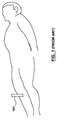
血管形成、ステント装着およびアテローム切除術のような、様々な心臓血管手術は、血管系への接近を要求する。図1及び2を参照して、患者の血管系への接近は、通常大腿動脈を通じてであり、針(示さず)の挿入、またいくつかのケースでは、拡張器(示さず)を含み経皮的であり、股間の領域において、皮下組織Tを通って進路103を形成し、穿刺し、大腿動脈の血管壁VW内に動脈切開VAを作り出す。ガイドワイヤGWが針を通して前進し大腿動脈内へ進む。針及び拡張器は、存在する場合は除去される。イントロデユーサーシース101は、通常近位端に止血弁を備える単一のルーメンカテーテルであり、または他の介入装置は、選択した処置を達成するために、進路103に沿ってガイドワイヤGWを越えて前進し大腿動脈内へ進む。イントロデユーサーシース101は、選択した処置を達成するために、動脈切開、より長いガイドワイヤ、カテーテルまたは他の手段を通じて、大腿動脈への接近を提供する。イントロデユーサーシースの止血弁は、無関係な出血戻りを防ぎ、または患者の身体への薬物を導入のために用いられる。
Various cardiovascular surgeries, such as angioplasty, stenting and atherectomy, require access to the vasculature. With reference to FIGS. 1 and 2, access to the patient's vasculature is usually through the femoral artery, including the insertion of a needle (not shown) and, in some cases, a dilator (not shown). In the crotch region, a path 103 is formed through the subcutaneous tissue T and punctured to create an arteriotomy V A in the vascular wall V W of the femoral artery. The guide wire GW advances through the needle and advances into the femoral artery. The needle and dilator are removed if present. Introducer
選択した処置の完了後、介入装置は除去され、動脈切開は閉鎖される。動脈内の穿刺開口のサイズは、用いたカテーテルのサイズまたは経皮的イントロデユーサーシースのサイズに対応し、また当該装置は、通常診断法用で5フレンチFrenchから治療手段用で6−20フレンチFrenchまでの直径の範囲であり得る。動脈切開の閉鎖及び治療を容易にする数多くの技術が知られている。一つの技術は、比較的長時間穿刺部位への圧力の適用を含む。より詳しくは、圧迫は伝統的には、カテーテル除去後、創傷が自然に閉鎖するために少なくとも30−45分間穿刺部位へ適用される。出血が停止することを保証するために数時間、患者は、横になったままで、実質的には静止し、しばしば重い砂袋を上脚に置いたような状態を要求される。医療処置の回復時間は、早くて30分間はかかり得るが、創傷からの回復は、24時間を超えることがある。長い回復時間は、費用の増加、患者の苦痛を増し、合併症の危険性をもたらし得る。動脈切開閉鎖への他の接近は、圧迫鉗子装置、血栓性またはコラーゲンプラグ、アテローム切除術に適用される生物学的接着剤及び/または綴じ装置である。 After completion of the selected procedure, the interventional device is removed and the arteriotomy is closed. The size of the puncture opening in the artery corresponds to the size of the catheter used or the size of the percutaneous introducer sheath, and the device is usually used for diagnostic methods from 5 French to 6-20 French for treatment. Can range in diameter up to French. Numerous techniques are known that facilitate the closure and treatment of arteriotomy. One technique involves the application of pressure to the puncture site for a relatively long time. More particularly, compression is traditionally applied to the puncture site for at least 30-45 minutes after the catheter is removed to allow the wound to naturally close. For several hours to ensure that the bleeding stops, the patient is required to remain lying down and substantially rest, often with a heavy sandbag on the upper leg. The recovery time for a medical procedure can be as fast as 30 minutes, but recovery from a wound can exceed 24 hours. Long recovery times can increase costs, increase patient pain, and pose a risk of complications. Other approaches to arteriotomy closure are compression forceps devices, thrombotic or collagen plugs, biological adhesives and / or binding devices applied to atherectomy.
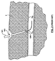
さらに、医療縫合システムは、動脈切開の閉鎖及び治療を容易にし、血管カテーテル法処置後の動脈切開閉鎖にかかわる懸念のいくつかを解決する。さらに、動脈切開閉鎖への活用を越えて、執刀医は、内部切開閉鎖、創傷さもなければ原位置縫合での組織部分の接合への必要性にしばしば遭遇する。例えば、図3は、患者への経皮的または最小限の侵襲的治療を達成するために用いる患者の皮膚の切開310を説明する。患者への治療後、縫合312は、取り出す組織部分316、318(図3のファントム図法で示す)のために、イントロデユーサーシース301を通じて患者の内部へ導入される。縫合312の二つの端部分320、322は、例えば、血管または器官内の内部創傷または動脈切開の結果であり得るそれぞれ組織部分316、318から伸びる。縫合312は、これらに限定されないが、2013年3月13日出願、U.S.Pat.No.6,117,144、ノーベル(nobles)ら、U.S.Pat.No.6,562,052、ノーベル(nobles)ら、U.S.Pat.No.7,803,167、ノーベル(nobles)ら、U.S.Appl.No.13/802,551,Argentine,及び2013年3月13日出願、U.S.Appl.No.13/802,563,Argentine,に記述されているようなあらゆる適切な方法及び装置で組織部分316、318を通じて患者の内部へ導入、並びに配置され、その全ては、その全体が参照することにより本書に援用される。図3にカテーテルシース導入器301から伸びる縫合312を示すが、代わりに患者内の切開310から直接伸び得る。
In addition, the medical suturing system facilitates the closure and treatment of arteriotomy and solves some of the concerns associated with arteriotomy closure after vascular catheterization procedures. In addition, beyond the application to arteriotomy closure, surgeons often encounter the need for internal incision closure, wound or otherwise in situ tissue joining. For example, FIG. 3 illustrates a patient's
縫合312の組織部分通過後、即ち、縫合が内部創傷または動脈切開に隣接する配置状態の後、縫合312の二つの端部分320、322は、結束され、さもなければ連結され、二つの組織を取り出し、かつ分離を防がなければならない。二つの端部分320、322は、執刀医により手動で結束され得る。しかし、縫合は、しばしば操作及び/または接近に困難し、治療時間を増加する。従って、ある症例では、執刀医は、原位置で二つの端部分を固定するかまたは連結する装置を用いることを選ぶ。例えば、本出願と同じ譲渡人に譲渡され、その全体を参照により本明細書に援用するU.S.Pat.No.8,197,497、及びU.S.Pat.No.8,469,975、ノーベル(nobles)ら、は、原位置縫合の二つの端部分を固定または連結する結節または接合具を配置する結節配置装置を記述している。結節は、結節本体及び栓を含み、結節配置装置は、栓を結節本体内の遠位へ押し込み、栓と結節本体との間の少なくとも二つの縫合部分を補足する。結節、即ち、捕捉した縫合部分を有する結節本体及び栓は、次に結節配置装置から追い出される。結節配置装置から追い出される場合、結節は、治療部位の開口または動脈切開を通じて不注意に押し出され得る。動脈切開を通じて不注意に押し出す場合、止血を緩和または減少する可能性に加えて、結節は、切開/動脈切開の反対の内側血管壁に接触し、かつ損傷させ得る。
After passing the tissue portion of the
実施形態は、ふたつ以上の縫合部分を固定または連結する装置の改善に関する。 Embodiments relate to improvements in devices that secure or connect two or more suture portions.
実施形態は、縫合接合具配置装置及び縫合接合具を含む原位置縫合接合具を形成するためのシステムに関する。縫合接合具配置装置は、作動機構を有するハンドル、外側軸、中間軸及びプッシュロッドを含む。外側軸は、近位端からその遠位末端までの内腔を限定する。外側軸の近位端は、ハンドルに連結され、また外側軸は、遠位末端に隣接する側面の口を含む。中間軸は、近位端から遠位末端までの内腔を限定する。中間軸は、ハンドルの作動機構に連結される中間軸の近位端を備える外側軸の内腔内に摺動自在に配置される。プッシュロッドは、中間軸の内腔内に摺動自在に配置される。プッシュロッドの近位端は、ハンドルの作動機構に連結される。縫合接合具は、スリーブ及び栓を含む。縫合接合具が縫合接合具配置装置内に装着構成状態にある場合、縫合接合具のスリーブは、遠位末端に隣接する外側軸の内腔内の中間軸の外面上に配置され、また縫合接合具の栓は、スリーブに近接する中間軸の内腔内に摺動自在に配置される。 Embodiments relate to a system for forming an in-situ suture joint including a suture joint placement device and a suture joint. The suture connector placement device includes a handle having an actuation mechanism, an outer shaft, an intermediate shaft, and a push rod. The outer shaft defines a lumen from the proximal end to its distal end. The proximal end of the outer shaft is coupled to the handle and the outer shaft includes a side port adjacent to the distal end. The intermediate shaft defines a lumen from the proximal end to the distal end. The intermediate shaft is slidably disposed within the lumen of the outer shaft with the proximal end of the intermediate shaft coupled to the handle actuation mechanism. The push rod is slidably disposed in the lumen of the intermediate shaft. The proximal end of the push rod is connected to the actuation mechanism of the handle. The suture joint includes a sleeve and a plug. When the suture connector is in a mounted configuration within the suture connector placement device, the sleeve of the suture connector is disposed on the outer surface of the intermediate shaft within the lumen of the outer shaft adjacent the distal end and is also suture bonded. The instrument plug is slidably disposed within the lumen of the intermediate shaft proximate the sleeve.
実施形態は、同様に、縫合接合具配置装置及び縫合接合具を含む原位置縫合接合具を形成するためのシステムに関する。縫合接合具配置装置は、作動機構を有するハンドル、外側軸、中間軸及びプッシュロッドを含む。外側軸は、近位端からその遠位末端までの内腔を限定する。外側軸の近位端は、ハンドルに連結され、また外側軸は、遠位末端に隣接する側面の開口を含む。外側軸の遠位末端は、血管壁の外面で終端となるように構成される。中間軸は、近位端からその遠位末端までの内腔を限定する。中間軸は、ハンドルの作動機構に連結される中間軸の近位端を備える外側軸の内腔内に摺動自在に配置される。作動機構は、中間軸を近位に後退するように構成される。プッシュロッドは、中間軸の内腔内に摺動自在に配置される。プッシュロッドの近位端は、ハンドルの作動機構に連結され、また作動機構は、プッシュロッドを遠位へ前進させるように構成される。縫合接合具は、弾性物質から作られたスリーブ及び栓を含む。縫合接合具が縫合接合具配置装置内に装着構成状態にある場合、縫合接合具のスリーブは、遠位末端に隣接する外側軸の内腔内の中間軸外面上に配置され、また縫合接合具の栓は、スリーブに近接する中間軸の内腔内に摺動自在に配置される。プッシュロッドの遠位前進は、スリーブ内の栓を縦の位置へ移動させ、及び中間軸の近位後退は、スリーブを栓の上に解放する。 Embodiments also relate to a system for forming an in-situ suture joint including a suture joint placement device and a suture joint. The suture connector placement device includes a handle having an actuation mechanism, an outer shaft, an intermediate shaft, and a push rod. The outer shaft defines a lumen from the proximal end to its distal end. The proximal end of the outer shaft is coupled to the handle and the outer shaft includes a side opening adjacent to the distal end. The distal end of the outer shaft is configured to terminate at the outer surface of the vessel wall. The intermediate shaft defines a lumen from the proximal end to its distal end. The intermediate shaft is slidably disposed within the lumen of the outer shaft with the proximal end of the intermediate shaft coupled to the handle actuation mechanism. The actuation mechanism is configured to retract the intermediate shaft proximally. The push rod is slidably disposed in the lumen of the intermediate shaft. The proximal end of the push rod is coupled to the actuation mechanism of the handle, and the actuation mechanism is configured to advance the push rod distally. The suture joint includes a sleeve and a stopper made from an elastic material. When the suture connector is in a mounted configuration within the suture connector placement device, the suture connector sleeve is disposed on the outer surface of the intermediate shaft within the lumen of the outer shaft adjacent the distal end, and the suture connector. The plug is slidably disposed within the lumen of the intermediate shaft proximate to the sleeve. The distal advancement of the push rod moves the plug in the sleeve to a vertical position and the proximal retraction of the intermediate shaft releases the sleeve over the plug.
実施形態は、同様に、生体組織内の開口から伸びる二つの縫合部分の固定用方法に関する。二つの縫合部分は、縫合接合具のスリーブ内に配置される。スリーブは、遠位末端に近接する側面の開口を備える外側軸を含む縫合接合具配置装置内に配置され、中間軸は、外側軸の内腔を通って摺動自在に配置され、またプッシュロッドは、中間軸の内腔を通って摺動自在に配置される。縫合接合具のスリーブは、遠位末端に隣接する外側軸の内腔内の中間軸の外面上に配置され、及び縫合接合具の栓は、スリーブに近接する中間軸の内腔内に摺動自在に配置される。外軸の遠位末端が血管壁の外面で終端となるように、また生体組織の開口を囲むまで、外側軸は前進する。栓がスリーブ内の縦方向に配置するまで、栓を中間軸の内腔内に摺動させるために、プッシュロッドは、中間軸に対して遠位へ前進する。スリーブが栓上に解放し、スリーブと栓との間の二つの縫合部分を固定するように、中間軸は、プッシュロッドに対して近位に後退し、スリーブを中間軸の外面との接触から解放する。 Embodiments also relate to a method for securing two suture portions extending from an opening in a living tissue. The two suture portions are disposed within the sleeve of the suture joint. The sleeve is disposed within a suture joint placement device including an outer shaft with a side opening proximate the distal end, the intermediate shaft is slidably disposed through the lumen of the outer shaft, and the push rod Is slidably disposed through the lumen of the intermediate shaft. The suture connector sleeve is disposed on the outer surface of the intermediate shaft in the lumen of the outer shaft adjacent to the distal end, and the plug of the suture connector slides into the lumen of the intermediate shaft proximate the sleeve. Arranged freely. The outer shaft is advanced so that the distal end of the outer shaft terminates at the outer surface of the vessel wall and surrounds the opening of the biological tissue. The push rod is advanced distally relative to the intermediate shaft to slide the plug into the lumen of the intermediate shaft until the plug is positioned longitudinally within the sleeve. The intermediate shaft is retracted proximally with respect to the push rod so that the sleeve releases onto the plug and secures the two stitched portions between the sleeve and the plug, and the sleeve is removed from contact with the outer surface of the intermediate shaft. release.
本発明の先行の及び他の特徴及び利点は、添付図において説明するように、実施形態の以下の記述から明白である。本発明明細書の一部を形成し組み込まれている添付図面は、さらに、本発明の原理を説明し、また当事者が本発明を作り使用することを可能にする。図面は尺度なしである。 The preceding and other features and advantages of the present invention will be apparent from the following description of embodiments, as illustrated in the accompanying drawings. The accompanying drawings, which form a part of the specification of the present invention, further illustrate the principles of the invention and enable the parties to make and use the invention. The drawings are not scaled.
具体的な実施形態は、図に参照番号をつけて記述し、参照番号は、同一のまたは機能的に等しい要素を示す。用語“遠位の”及び“近位”は、治療を行う医師に対する位置または方向に関して、以下の記述で用いられる。”遠位の“または” 遠位で“は、医師から遠位の位置または医師から離れた方向内である。”近位の“または”近位で“は、医師の近くの位置または医師に向う方向内である。 Specific embodiments are described with reference numerals in the figures, wherein the reference numerals indicate identical or functionally equivalent elements. The terms “distal” and “proximal” are used in the following description with respect to position or orientation relative to the treating physician. “Distal” or “distal” is in a position distal to or away from the physician. “Proximal” or “proximal” is in a position near or to the physician.
次の詳細記述は、事実上単に例示的にすぎず、本発明または本発明の適用及び使用を制約することを意図するものではない。以下に記述する実施形態は、患者の治療位置から伸びる二つの縫合部分を固定または連結する装置に関し、またはさもなければ、患者の治療位置から伸びる二つの縫合部分への接合具の適用を述べる。縫合部分は、同じ縫合の部分であり得、または分離した及び異なる縫合の部分であり得る。治療位置は、動脈または静脈血管のようなあらゆる望ましい位置であり得る。本発明の記述は、血管の治療の状況内ではあるが、本発明は、同様に有用と判断されるあらゆる他の身体通路内で用いられ得る。例えば、装置は、動脈管開存症、卵白孔開存症、心臓の欠陥、刺創等のような他の組織を縫合するために用いられ得る。先行する技術分野、背景、要約または以下の詳細記述に存在するあらゆる表現または含蓄された理論による拘束を意図するものではない。 The following detailed description is merely exemplary in nature and is not intended to limit the invention or the application and uses of the invention. The embodiments described below relate to an apparatus for securing or connecting two suture portions extending from a patient treatment location, or otherwise describing the application of a connector to two suture portions extending from a patient treatment location. The suture portions can be the same suture portion, or can be separate and different suture portions. The treatment location can be any desired location, such as an artery or venous vessel. Although the description of the present invention is within the context of vascular treatment, the present invention may be used in any other body passage that is also deemed useful. For example, the device can be used to suture other tissues such as patent ductus arteriosus, patent foramen ovale, heart defects, puncture wounds, and the like. It is not intended to be bound by any expressed or implied theory presented in the preceding technical field, background, summary or the following detailed description.
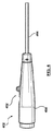
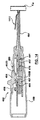
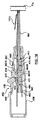
図4は、結節の配置または縫合接合具404の配置用縫合接合具配置装置402の側面図であり、一方図5は縫合接合具404の側面図である。縫合接合具配置装置402及び縫合接合具404は、全体として遠位末端縫合接合具を形成するシステム400と考えられる。縫合接合具配置装置402は、作動機構452およびハンドル450から遠位末端に伸びる外側軸464を有するハンドル450を含む。縫合接合具404は、円筒状部品または栓408及び通過する内腔407を限定する管状部品またはスリーブ406を含む。スリーブ406は、外面に放射状に伸びる円周フランジ405を含む。フランジ405は、より詳細に記述するように、操作中縫合接合具配置装置402と相互作用するように機能する。栓408は、スリーブ406の内腔407内へ挿入するように構成された外側寸法及び長さを有する。栓408は、より詳細に記述するように、栓及びスリーブが組立または接合する場合、栓408とスリーブ406との間の介入または圧入を固定するため外面に伸びる放射状突起409を含み得る。突起409は、輪、螺旋、スパイク、隆起または他の適切な構造であり得る。縫合接合具配置装置402内に装着する場合、以下により詳細に記述するように、スリーブ406及び栓408は、栓408がスリーブ406の近位に配置されるように、装置の遠位末端内に配置される。遠位末端縫合接合具404を全展開し、また形成するための縫合接合具配置装置402の操作には、二段階または二手段展開プロセスが考え得る。より詳細に記述する最初の展開操作の手段または段階では、スリーブ406及び栓408が展開の当該段階で各々とまだ接触してないけれども、縫合接合具配置装置402は、栓408を遠位へ前進させるかまたはスリーブ406内へ押し込まれる。一旦スリーブ及び栓が互いに縦方向に並ぶと、縫合接合具404は、展開前の構成状態となる。より詳細に記述するように、展開操作の第2番目の手段または段階では、縫合接合具配置装置402は、スリーブ406を栓408上で解放させ、栓とスリーブとの間の固定または締付した縫合部分(図4−5には示さず)が形成した接合具内で互いに対し共に縫合部分を固定または保持する。縫合部分は、栓408とスリーブ406との間の介入または圧入を介して、共に固定または連結される。一旦スリーブが栓上で解放されると、縫合接合具404が形成され、完全な展開構成状態となる。縫合接合具404は、血管または介入心臓カテーテル法に引き続く他の生体組織の開口または動脈切開に隣接して配置される縫合部分を固定するために用いられ得る、これにより止血を達成するために、開口または動脈切開を閉鎖または密封する。
FIG. 4 is a side view of a suture
縫合接合具404の正確な配置は、開口または動脈切開及び治療部位の止血にとって極めて重要である。縫合接合具404が治療部位の止血で正確に配置され、止血が行われていることを保証するために、縫合接合具配置装置402は、治療部位の開口または動脈切開にわたって覆って配置される遠位末端で、外側軸464が治療部位の組織で終端となるように設計され、また栓408がスリーブ406内に配置する後、縫合接合具404が装置を押さないようまたは追い出さないように設計される。当該設計は、縫合接合具404が治療部位の組織に対し正確に配置され、また治療部位の開口または動脈切開を通じて不注意に押さないように保証する。さらに、縫合接合具配置装置402は、栓408がスリーブ406内に配置後の縫合部分の調整を可能にするように設計される。装置が焼灼または展開するやいなや、栓とスリーブとの間の縫合部分を固定または締め付けるよりは、むしろシステム400の二段階展開は、ユーザーが、栓408がスリーブ406内に配置された後、即ち、縫合接合具404が展開前の状態後に必要となれば、治療部位で止血が達成されたことを保証するために、縫合部分を引っ張りまたは締め付けることを可能にする。縫合接合具配置装置402および接合具400のさらなる利点または改善は、図を参照して議論する。
The exact placement of the
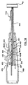
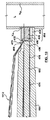
縫合接合具配置装置402の部品は、参照図6、6A及び7を使って記述する。図6は、図4の断面図で、図6Aは、図6のA−A線に沿った断面図であり、また図7は、図6の遠位部分の拡大図である。縫合接合具配置装置402は、外側軸464、中間軸474、プッシュロッド482及びスライダー454、最初の連結器451及び第2番目の連結器457を含む作動機構452を有するハンドル450を含む。縫合接合具配置装置402の当該部品は、制限しない金属、プラスチック及び金属とプラスチックの組合せのあらゆる適切な物質から作られ得る。図6Aによく示すように、中間軸474は、外側軸464の内腔472を通って摺動自在に配置され、またプッシュロッド482は、中間軸474の内腔480を通って摺動自在に配置される。外側軸464は、内腔472を限定する伸長管状部品であり、ハンドル450内に伸びて連結する近位端466を有する。外側軸464の遠位末端468は、血管壁または他の生体組織の外面に終端するように寸法合わせされ構成される。遠位末端468は、治療部位の開口または動脈切開にわたって覆うのに十分なサイズである。例えば、外側軸464の遠位末端468の外側直径は、15から20フレンチFrenchであり得る。外側軸464は、さらに、側面開口または遠位末端468の近くのポート470を含む。外側軸464の遠位末端468に隣接して、内腔472の遠位部分は、外側軸464の内面に沿った突合せ面469を作り出すために、残りの近位長さよりは大きな直径を有する。より詳細に記述するように、突合せ面469は、中間軸474が後退する場合、スリーブ406を動かないように保持する働きをする。
The components of the suture
より詳細に記述するように、中間軸474は、内腔480を限定する管状部品であり、作動機構452の第2番目の連結器457内に伸び取付けられる近位端476を有する。中間軸474の遠位末端478は、外側軸464の遠位末端468まで伸びる。中間軸474は、同様に、遠位末端478近くに側面開口またはポート479を含む。一つ実施形態においてより詳細に記述するように、中間軸474が縫合接合具配置装置402の操作中後退するので、側面ポート479は、遠位末端478まで伸び、装置操作中、中間軸474の側面ポート479と外側軸464の側面ポート470との整列を保証する。図11及び12を参照してより詳しく記述するように、縫合接合具404が縫合接合具配置装置402内で装着構成状態にある場合、図7の拡大図に示すように、縫合接合具404のスリーブ406は、外側軸の遠位末端468に隣接する外側軸464の内腔472内の中間軸474の外面上に配置される。縫合接合具404が図11及び図12を参照してより詳しく記述するように、縫合接合具404が縫合接合具配置装置402内で装着構成状態にある場合、縫合接合具404の栓408は、スリーブ406近くの中間軸474内に摺動自在に配置される。
As described in more detail, the
プッシュロッド482は、より詳しく記述するように、固体円筒形部品であり、作動機構452の最初の連結器451内に伸び取付けられる近位端484を有する。図7の拡大図に示すように、プッシュロッド482の遠位末端486は、図11及び図12を参照してより詳しく記述するように、縫合接合具404が縫合接合具配置装置402内で装着構成状態にある場合、栓408の近位端近くに位置するかまたは配置される。
The
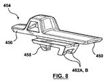
作動機構452は、スライダー454、プッシュロッド482の近位端484をスライダー454に連結する最初の連結器451、中間軸474の近位端476をスライダー454に連結する第2番目の連結器457を含む。作動機構452は、スライダー454と最初の連結器451との間の介入を介して、プッシュロッド482を遠位に前進させるように構成され、また同様に、スライダー454と第2番目の連結器457との間の介入を介して、中間軸474を近位に後退させるように構成される。有利的に、利用者の展望から作動機構452の操作は、スライダー454だけの相互作用を必要とし、この場合、プッシュロッド408をスリーブ406内へ押し込むため、展開の最初の手段または段階で使用するスライダー454の遠位前進、また中間軸474を後退させるため展開の第2番目の手段または段階を使用するスライダー454の近位後退を要求し、これによりスリーブ406を栓408上で解放する。さらに詳細に説明すると、スライダー454は、上面がユーザーに接近可能で、底部または下面が作動機構452の残りの部品と相互作用するように、ハンドルの凹所449内に収容される。図8を追加参照して、スライダー454は、下面上に最初のノブまたはボス458を有する近位端456及び下面上に一組の相隔たるノブまたはボス462A、462Bを有する遠位末端460を含む。図9を追加参照して、最初の連結器451は、プッシュロッド482の近位端484を受けるために少なくとも遠位部分を通る内腔453を含む。最初の連結器451は、同様に、相互作用またはスライダー454の最初のノブ458と係合のために、スライダー454に向う上方向内に伸びる遠位末端でノブまたはボス455、またより詳しく記述するように、伸長構成内に連結される最初の連結器451及びプッシュロッド482を固定するためのスライダー454から離れて下方へ伸びる近位端で蟻継ぎ443を含む。図10を追加参照して、第2番目の連結器457は、中間軸474を通って摺動自在に配置し、最初の連結器451の近位に伸びるプッシュロッド482だけでなく、中間軸474の近位端476を受けるためそこを通る内腔459をも含む。第2番目の連結器457近位部分は、同様に、スライダー454の一組の相隔たるノブまたはボス462A、462Bと相互作用または係合するために、反対側の二つの相隔たるレール461A、461Bを含む。レール461A、461Bの近位端は、より詳しく記述するように、スライダー454の遠位ノブ462A、462Bを一時的に収容するために形成された溝または結節465A、465Bを含む。
The
縫合接合具配置装置402が、縫合接合具404内の一つ以上の縫合の部分を締付または固定するために活用されるので、縫合部分は、血管の動脈切開の境界または縁に周りに予め配置され、図11−20を参照して、生体組織内の開口から伸びる二つの縫合部分を固定するために、縫合接合具配置装置を活用する方法を同時に記述する一方で、縫合接合具配置装置の部品については、さらに記述する。図11、12及び12Aを参照して、縫合接合具配置装置402の横断面図で血管の血管壁Vw内の動脈切開VAを有する組織に隣接する縫合接合具配置装置の遠位末端を示す。図12が縫合接合具配置装置のハンドル450をも図示する一方で、図11は、縫合接合具配置装置の遠位末端のみの拡大図である。図11Aは、縫合接合具配置装置の遠位末端の透視図であり、また図12Aは、ハンドル450の部分の透視図である。
Since the suture
図11、11A、12及び12Aにおいて、縫合接合具404は、縫合接合具配置装置402内で装着または送達構成状態にある。より具体的には、縫合接合具404が装着構成状態にある場合、縫合接合具404のスリーブ406は、外側軸464と外側軸464の遠位末端468に隣接する中間軸474との間に放射状に配置される。つまり、縫合接合具404のスリーブ406は、外側軸の遠位末端468に隣接する外側軸464の内腔内に内腔472内の中間軸474の外面上に配置される。スリーブ406のフランジ405は、外側軸464の突合せ面469に終端するかまたはそれに隣接する。縫合接合具404の栓408は、スリーブ406の近位端の近接する中間軸474の内腔480内に配置される。さらに、プッシュロッド482の遠位末端486は、栓408の近位端に近接して配置される。中間軸474の遠位末端478は、外側軸464の遠位末端468と同一平面であるだけでなく、スリーブ406の遠位末端とも同一平面に配置される。中間軸474の側面ポート479は、外側軸464の側面ポート470と周辺に並べる。スライダー454の近位端456は、最初の連結器451のノブ455に終端するスライダー454のノブ458で、ハンドル450内の凹所449の近位表面447に終端する。第2番目の連結器457は、第2番目の連結器457がハンドル450の遠位末端部分内に形成された内面または栓441に終端するように、ハンドル450の遠位部分内に配置される。図12Aの透視図よく示すように、スライダー454の遠位ノブ462A、462Bは、第2番目の連結器457のレール461A、461Bの近位端上に形成された溝または結節465A、465B内に配置または収容される。
In FIGS. 11, 11A, 12 and 12A, the
縫合部分1112は、図11−12内の縫合接合具配置装置402の遠位部分内に配置して示す。縫合部分1112は、縫合接合具配置装置の遠位末端に入り、縫合接合具404のスリーブ406の内腔407を通って伸び、またそれぞれ外側軸464、中間軸474の整列した側面ポート470、479を介して、縫合接合具配置装置402を出る。縫合部分1112は、血管の血管壁Vw内の動脈切開VAの境界または縁の周りに予め配置された一つ以上の縫合の部分である。例示縫合物質は、制限なしで、単繊維またはポリプロピレンのようなプラスチック縫合物資を含む。図11−12の縫合接合具404の装着構成状態において、また図11Aの透視図に最良に示すように、縫合部分1112は、配置されまたはそれぞれ外側軸464、中間軸474の整列した側面ポート470、479を介して、スリーブ406を通って伸びる。縫合部分を縫合接合具配置装置内へ配置または装着するために、縫合接合具配置装置402は、参照することになり本明細書に組込まれるU.S.Patent No.8,197,497及び8,469,975、ノーベル(Nobles)ら両方に記述されるように、予め組み込まれた糸通器(示さず)を含み得る。糸通器は、タブ及び外側軸464及びスリーブ406と中間軸474との間の側面ポートを470通り抜ける環状ワイヤを含む。縫合部分1112は、ワイヤの環状端を通り抜け、またタブは、縫合部分1112がスリーブ406を通って縫合接合具配置装置内へ配置するために、近位に引寄せられる。
The
遠位末端468が動脈切開VAの境界または縁の周りの血管壁の外面に接触し、かつ終端になるまで、縫合接合具配置装置402が、前進する間、縫合部分1112は、手またはほかの方法で緊張状態に保持され得る。図11に示すように、外側軸464の遠位末端468は、血管壁Vwの外面で終端となるように、突出しないように、また動脈切開VAを通って血管の内腔L内へ伸長しないように寸法合わせされる。ユーザーが縫合接合具配置装置402を動脈切開VAへ前進する場合、遠位末端468が血管壁に接触する場合、更なる前進への抵抗が感じられ、縫合接合具配置装置が動脈切開VAに隣接する所望の適所にあることをユーザーに通知する。
While the suture
縫合接合具404の展開を始める場合、スライダー454は、図13及び14に示すように、スリーブ406に向って栓408を遠位へ前進させるために、図13は、遠位へ前進される。図14が、縫合接合具配置装置のハンドル450をも説明する一方で、図13は、縫合接合具配置装置の遠位末端のみの拡大図を示す。より詳しくは、作動機構452のスライダー454が遠位へ前進または前方へ押す場合、スライダー454のノブ458は、最初の連結器451のノブ455を押しまたは遠位へ前進させ、されにより、連結器451及びプッシュロッド482を遠位へ前進させる。プッシュロッド482の遠位末端486は、中間軸474を通って栓408に接触し、かつ遠位へ前進させる。従って、スライダー454の遠位への前進は、同様に、プッシュロッド482及び栓408を調和して遠位へ前進させる。プッシュロッド482の前進の間、中間軸474は、外側軸464の遠位末端468と同一平面であるだけでなく、スリーブ406の遠位末端とも同一平面に配置する遠位末端478で静止している。さらに、プッシュロッド482の遠位前進の間、スライダー454の遠位ノブ462A、462Bは、第2番目の連結器457のレール461A、461Bの遠位端上に形成された溝または刻み目465A、465Bから出てまたは除外され、また遠位ノブ462A,462Bは、第2番目の連結器457のレール461A、461Bに乗りまたは越える。より詳しくは、第2番目の連結器457の遠位末端が、ハンドル450の遠位末端部分内で形成された栓441で終端となるので、第2番目の連結器457および連結する中間軸474は、固定されまたロックされて、最初の連結器451及びプッシュロッド482の遠位前進の間、不注意に遠位へ前進され得ない。スライダー454の遠位ノブ462A、462Bが遠位へ前進する場合、固定された第2番目の連結器457で、レール461A、461Bは、板バネであり、スライダー454から離れて下方向に曲げられる。さらに、プッシュロッド482の前進の間、縫合接合具404のスリーブ406は、外側軸464と外側軸464の遠位末端468に隣接する中間軸474との間に放射状に配置される。縫合部分1112は、プッシュロッド482及び栓408の遠位前進の間、手で、またはさもなければ他の方法で、引っ張り保持される。
When starting deployment of the
スライダー454は、図15及び16に示す位置まで遠位に前進され、遠位末端460は、ハンドル450内の凹所449の遠位面445で終わり、また栓408は、スリーブ406内に配置される。図16が縫合接合具配置装置のハンドル450をも説明する一方で、図15は、縫合接合具配置装置の遠位末端のみの拡大図である。図16Aは、ハンドル450の部分の透視図である。栓408は、スリーブ406内に配置されるけれど、中間軸474が当該間に放射状に配置されるので、栓408及びスリーブ406は、未だ接触していない。使用の方法の本時点では、スライダー454及びプッシュロッド482は、互いに伸長位置であり、また縫合接合具404の栓408がスリーブ406内へ伸長または後退するが、未だスリーブ406と接触していないので、縫合接合具404は、装着前の構成状態であると考えられ得る。図16Aによく示すように、スライダー454及びプッシュロッド482が伸長構成状態にある場合、最初の連結器451の近位端での蟻継443は、最初の連結器451及び伸長構成ないで連結されたプッシュロッド482を固定するために、ハンドル450内に形成された凹所または刻み目467内に伸長しまたは収容される。伸長位置状態のスライダー454で、スライダー454の遠位ノブ462A、462Bは、第2番目の連結器457のレール461A、461Bの遠位を通り越えまたは遠位に位置する。スライダー454の遠位ノブ462A、462Bが板ばね特性により、もはやレール461A、461Bに下方へ曲がるようにしなくなる後、レール461A、461Bは、レール461A、461Bの遠位面463A、463Bを係合し、また終端となる遠位ノブ462A、462Bで上方へ撥ね、かつ正常位置と推定される。縫合部分1112は、展開の本段階で効果的に調整されまたは締められる。従って、栓408の遠位前進が縫合部分1112の緩みまたは動きをもたらす場合、スリーブ406内の栓408の配置の手段の間または後に、張力または他の調整が縫合部分1112に適用される。
一旦、縫合部分1112が、所望の調整または締められると、中間軸474は、スリーブ406が栓408上に開放するために、近位に後退する。より詳しくは、接合具404の完全展開状態にあるのを望む場合、スライダー454は、図17及び18に示すように、中間軸474がスリーブ406から離れて近位に後退するために、近位に後退する。図18が縫合接合具配置装置のハンドル450をも説明する一方で、図17は、縫合接合具配置装置の遠位末端のみの拡大図である。より詳しくは、作動機構452のスライダー454が近位に後退するか、または後方へ引っ張られる場合、スライダー454の一組のノブ462A、462Bは、第2番目の連結器457のル461A、461Bの遠位面463A、463Bを係合または終端となる。図15は、断面図で、ノブ462B及びレール461Bのみが示されるが、ノブ462A及びレール461Aは、それぞれ図10に示すようにノブ462B及びレール461Bの鏡像であり、またそのように、当該間の相互作用は同じである。従って、スライダー454は、第2番目の連結器457のレール461A、461Bを押しまたは近位に後退させ、それによって、第2番目の連結器457及びそれに取付けた中間軸474を近位に後退させる。スライダー454の中間軸474の後退の間、スライダー454のノブ458は、もはや最初の連結器451のノブ455と接触はなく、またプッシュロッド482が中間軸474の後退の間、プッシュロッド482が伸長位置内に静止しているように、第2番目の連結器457のレール461A、461B間の空間を通過するか空間内に摺動する。さらに、ハンドル450の凹所または刻み目467内に固定される最初の連結器451の近位端で蟻継443は、プッシュロッド482(最初の連結器451に取付けられる)が不注意に中間軸474を後退しないことを保証する。伸長位置内にプッシュロッド482を固定した状態で、中間軸474の後退間、栓408は、スリーブ406内に確実に残る。さらに、中間軸474の後退間、スリーブ406上形成されたフランジ405は、スリーブ406が不注意に中間軸474を後退しないことを保証するために、外側軸464内に形成された表面469を係合し、または終端となる。従って、突合せ面469とスリーブ406のフランジ405との間の相互作用は、中間軸474が後退している場合、スリーブ406は、静止し保持されていることを保証する。
Once the
スライダー454は、図19及び20に示す位置へ近位に後退し、近位端456は、ハンドル450内の凹所449の近位面447で終端となり、また中間軸474の遠位末端478は、栓408及びスリーブ406の近位端に近位に配置される。図20が縫合接合具配置装置のハンドル450をも説明する一方で、図19は、縫合接合具配置装置の遠位末端のみの拡大図である。図20Aは、ハンドル450の部分の拡大図である。中間軸474が栓408とスリーブ406の間から除去された状態で、スリーブ406は、栓408上の接触または締付を解放し、スリーブと栓との間の縫合部分1112を固定する。言い換えれば、中間軸474が後退する場合、スリーブ406は、もはや中間スリーブ474の外側面と接触しなく、スリーブ406は、それにより栓408上に解放し、栓408を包装し、覆い、包みまたはさもなければ囲む。スリーブ406が栓408上に解放される場合、栓408の放射状突起409は、スリーブと栓との間の接触により圧迫または平坦化され得、当該間の介入または圧入を確認する。実施形態において、スリーブ406は、エラストマーのような、しかし制限しない、弾性または伸縮性物質から形成される。実施形態では、スリーブ406は、シリコーンから形成される。上述したように、縫合接合具404の装着構成においては、スリーブ406は、中間軸474上を伸長または拡張し、また中間軸474は、後退する場合、スリーブ406は、栓408上に弾性的に接触し、または圧迫する。使用の方法の本時点で、スライダー454及び中間軸474は、互いに後退位置にあり、栓408が当該間に挟まれた縫合部分1112を備えたスリーブ406と接触状態にあるので、縫合接合具404は、完全展開構成状態にある。言い換えれば、スリーブ406が栓408上に解放される場合、栓とスリーブとの間に伸びる縫合部分1112は、形成した縫合接合具404内で互いに対し固定される。
他の実施形態では、中間軸474の後退による縫合接合具404の栓408とスリーブ406との間の接触を確認するために、縫合接合具の栓は、弾性または伸縮性物質から形成され、追加して、代替品としてスリーブは弾性物質から形成する。より詳しくは、栓408が中間軸に対して移動可能でまたは摺動自在であるように、栓408は、中間軸474内へわずかに圧縮される弾性物質から形成される。栓408がスリーブ406内に縦方向に、また中間軸474が後退した後、栓408は、弾性的に放射状に伸長しスリーブ406に接触し、スリーブと栓との間の縫合部分1112を固定する。
In other embodiments, to confirm contact between the
中間軸474の後退に際して、縫合接合具配置装置が近位に後退する場合、縫合接合具が遠位末端に残るように、縫合接合具404は、まだ縫合接合具配置装置402の外側軸内に配置されているが、そこから分離されている。従って、縫合接合具配置装置402が近位に後退し、また患者から取り外され場合、縫合接合具404は、固定された縫合部分1112を遠位末端に残す。縫合接合具404を縫合接合具配置装置402から押したりまたは追い出したり要求はないので、縫合接合具404は、さもなければ、縫合接合具404が縫合接合具配置装置402から押したりまたは追い出したり要求される場合よりもより剛性の少ないまたはより硬質性の少ない物質から形成され得る。実施形態では、スリーブ406は、シリコーンから形成され、また栓408は、コラーゲンから形成される。当該物質は、非常に生体適合性があり、またさもなければ、縫合接合具404が縫合接合具配置装置402から押したりまたは追い出したり要求される場合、好ましい剛性または硬質性であり得る。他の実施形態では、スリーブ406及び栓408は、制限しない、ポリプロピレンのような、より剛性で生体適合性の物質から形成され得る。
Upon retraction of the
縫合接合具404の物質に加えて、スリーブ406が中間軸の後退を介して、弾性的に栓408上に解放し、また装置、かつ形成した接合具を押したりまたは追い出したり要求しなくてもよい事実から有用な流れまたは結果がある。より詳しくは、縫合接合具配置装置から形成した接合具を押すまたは追い出すことは、血管の血管壁VW内の動脈切開VAを通じて接合具を押出す結果となり得る。不注意に動脈切開を通じて押す場合、縫合接合具404は、切開/動脈切開の反対側の内側血管壁に接触し、かつ損傷し得る。さらに、不注意に動脈切開を通じて押す場合、縫合接合具404は、治療部位の全閉鎖及び止血という結果になる。
In addition to the material of the suture joint 404, the
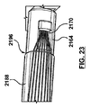
図21、22及び23は、縫合接合具配置装置2101の別の実施形態を説明する。縫合接合具配置装置2101は、縫合接合具配置装置2101がさらに外側軸2164にわたって回転自在に配置された最外側軸2188を含むことを除けば、ハンドル2150及び外側軸2164は上述の接合具配置402と同等である。最外側軸2188はハンドル2150に隣接して配置する近位端2190及び外側軸2164の側面ポートまたは開口2170に近接して配置する遠位末端2192を有する管状部品である。最外側軸2188は、内腔2194(図21にファントム図法で示す)。最外側軸2188の遠位末端2192は、縫合に役立つ操作可能な切断面2196を含む。最外側軸2188の近位端2190は、外側軸2164に対して外側軸の回転用輪2198を含む。縫合接合具の形成後、即ち、栓が当該間に挟まれた縫合部分を備えたスリーブと接触する状態にある後、ユーザーは、輪2188を介して、外側軸2164に対して最外側軸2188を回転し得、また切断面2196は、外側軸2164の側面ポート2170から伸びる所で隣接する縫合部分に役立つ。別の実施形態では、縫合部分は、切断し得る。
21, 22 and 23 illustrate another embodiment of a suture connector placement device 2101. FIG. The suture connector placement device 2101 includes the
本発明に従って、様々な実施形態が上述される一方で、それらは説明及び例示のみで制限のない方法で示されていることが理解できる。形式及び詳細において、様々な変化が本発明の精神と範囲を逸脱することなく、なされることが当事者において明白である。従って、本発明の広がり及び範囲は、あらゆる上述の例示実施形態で制限されないが、添付の請求項及び同類に従ってのみ限定される。同様に、論述した各実施形態の特性と組み合わせて用いられ得る。発明及び刊行物の全ては、参照することにより本書に援用される。 While various embodiments have been described above in accordance with the present invention, it can be appreciated that they have been presented in an illustrative and non-limiting manner only. It will be apparent to those skilled in the art that various changes in form and detail may be made without departing from the spirit and scope of the invention. Accordingly, the breadth and scope of the present invention is not limited in any of the above-described exemplary embodiments, but is limited only in accordance with the appended claims and the like. Similarly, it can be used in combination with the characteristics of each embodiment discussed. All inventions and publications are incorporated herein by reference.
Claims (13)
縫合接合具配置装置を有し、この縫合接合具配置装置は、
作動機構を有するハンドルと、
近位端からその遠位末端までの内腔を形成する外側軸であって、前記外側軸の近位端が前記ハンドルに連結し、前記外側軸が前記遠位末端に隣接する側面の開口を含む前記外側軸と、
近位端からそれの遠位末端までの内腔を形成する中間軸であって、この中間軸が前記ハンドルの前記作動機構に連結する前記中間軸の近位端を備え、前記外側軸の前記内腔内に摺動自在に配置される前記中間軸と、
前記中間軸の前記内腔内に摺動自在に配置されるプッシュロッドであって、このプッシュロッドの近位端が前記ハンドルの前記作動機構に連結される前記プッシュロッドと、を備え、
さらに、スリーブ及び栓を備える縫合接合具を有し、この縫合接合具が前記縫合接合具配置装置で装着構成状態にある場合、前記縫合接合具の前記スリーブが前記遠位末端に隣接する前記外側軸の前記内腔内の前記中間軸の外面上に配置され、前記縫合接合具の前記栓が前記スリーブの近位に前記中間軸の前記内腔内に摺動自在に配置されており、
前記作動機構は、前記栓が前記スリーブ内に縦方向に配置されるまで、前記中間軸に対する前記プッシュロッドの遠位前進が前記中間軸の前記内腔内への前記栓の摺動を可能にし、
前記作動機構は、前記プッシュロッドに対して前記中間軸が近位側に後退すると、前記スリーブが前記中間軸の前記外面との接触から解放されると共に、前記スリーブと前記栓が接触することを特徴とする遠位末端縫合接合具形成用システム。 A distal end suture joint forming system comprising:
The suture joint placement device has a suture joint placement device,
A handle having an actuation mechanism;
An outer shaft forming a lumen from a proximal end to its distal end, wherein the proximal end of the outer shaft is coupled to the handle and the outer shaft has a lateral opening adjacent to the distal end. Including the outer shaft;
An intermediate shaft forming a lumen from a proximal end to a distal end thereof, the intermediate shaft comprising a proximal end of the intermediate shaft coupled to the actuation mechanism of the handle, the intermediate shaft The intermediate shaft slidably disposed within the lumen;
A push rod slidably disposed within the lumen of the intermediate shaft, the push rod having a proximal end connected to the actuating mechanism of the handle;
And further comprising a suture joint comprising a sleeve and a plug, wherein the suture joint is in an installed configuration with the suture joint placement device, wherein the sleeve of the suture joint is adjacent to the distal end. Disposed on the outer surface of the intermediate shaft within the lumen of the shaft, and the stopper of the suture joint is slidably disposed within the lumen of the intermediate shaft proximal to the sleeve;
The actuating mechanism allows the distal advancement of the push rod relative to the intermediate shaft to allow the plug to slide into the lumen of the intermediate shaft until the plug is disposed longitudinally within the sleeve. ,
Said actuating mechanism, before Symbol retracted against the push rod to the intermediate shaft is proximally Then, together with the sleeve is released from contact with said outer surface of said intermediate shaft, the said sleeve plug contacts A system for forming a distal end suture joint.
縫合接合具配置装置を有し、この縫合接合具配置装置は、
作動機構を有するハンドルと、
近位端からそれの遠位末端までの内腔を形成する外側軸であって、前記外側軸の近位端が前記ハンドルに連結し、前記外側軸がその前記遠位末端に隣接する側面の開口を含み、前記外側軸の遠位末端が血管壁の外面に接触するように構成された前記外側軸と、
近位端からその遠位末端までの内腔を形成する中間軸であって、この中間軸の近位端が前記ハンドルの前記作動機構に連結された状態で、前記外側軸の前記内腔内に摺動自在に配置され、前記作動機構が前記中間軸を近位側に後退させるように構成されている前記中間軸と、
前記中間軸の前記内腔内に摺動自在に配置されるプッシュロッドであって、このプッシュロッドの前記近位端が前記ハンドルの前記作動機構に連結され、前記作動機構が前記プッシュロッドを遠位側に前進させるように構成されている前記プッシュロッドと、を備え、
さらに、弾性物質で形成されたスリーブ及び栓を備える縫合接合具を有し、この縫合接合具が前記縫合接合具配置装置で装着構成状態にある場合、前記縫合接合具の前記スリーブが前記遠位に隣接する前記外側軸の前記内腔内の前記中間軸の外面上に配置され、前記縫合接合具の前記栓が前記スリーブの近位に前記中間軸の前記内腔内に摺動自在に配置されており、
前記プッシュロッドの遠位への前進が前記栓を動かし、前記スリーブ内に前記栓を長手方向に配置させ、また、前記プッシュロッドに対して前記中間軸が近位側に後退すると、前記スリーブが前記中間軸の前記外面との接触から解放されると共に、前記スリーブと前記栓が接触するように構成されていることを特徴とする遠位末端縫合接合具形成用システム。 A distal end suture joint forming system comprising:
The suture joint placement device has a suture joint placement device,
A handle having an actuation mechanism;
An outer shaft forming a lumen from a proximal end to a distal end thereof, wherein the proximal end of the outer shaft is coupled to the handle and the outer shaft is adjacent to the distal end The outer shaft comprising an opening, the distal end of the outer shaft configured to contact an outer surface of a vessel wall;
An intermediate shaft defining a lumen from a proximal end to a distal end thereof, the proximal end of the intermediate shaft being coupled to the actuating mechanism of the handle; The intermediate shaft is slidably disposed and the actuating mechanism is configured to retract the intermediate shaft proximally;
A push rod slidably disposed within the lumen of the intermediate shaft, the proximal end of the push rod being coupled to the actuating mechanism of the handle, the actuating mechanism moving the push rod away from the push rod; The push rod configured to be advanced to the rear side, and
And further comprising a suturing joint comprising a sleeve formed of an elastic material and a stopper, wherein the suturing joint is in the mounted configuration state with the suturing joint placement device, the sleeve of the suturing joint being the distal Disposed on the outer surface of the intermediate shaft within the lumen of the outer shaft adjacent to the outer shaft and the stopper of the suture joint is slidably disposed within the lumen of the intermediate shaft proximal to the sleeve Has been
Moving forward said plug in the distal of the push rod, the stopper is disposed longitudinally within said sleeve, also retract the intermediate shaft proximally relative to the push rod Then, the sleeve wherein with the contact touch or we release the outer surface, a distal end suturing connectors forming system, characterized in that the said sleeve plug is configured to contact the intermediate shaft.
Applications Claiming Priority (3)
| Application Number | Priority Date | Filing Date | Title |
|---|---|---|---|
| US14/180,016 US9629620B2 (en) | 2014-02-13 | 2014-02-13 | Method and apparatus for forming a suture connector in situ |
| US14/180,016 | 2014-02-13 | ||
| PCT/US2015/011519 WO2015122987A1 (en) | 2014-02-13 | 2015-01-15 | Method and apparatus for forming a suture connector in situ |
Publications (3)
| Publication Number | Publication Date |
|---|---|
| JP2017506104A JP2017506104A (en) | 2017-03-02 |
| JP2017506104A5 JP2017506104A5 (en) | 2018-02-08 |
| JP6570534B2 true JP6570534B2 (en) | 2019-09-04 |
Family
ID=52464570
Family Applications (1)
| Application Number | Title | Priority Date | Filing Date |
|---|---|---|---|
| JP2016551765A Expired - Fee Related JP6570534B2 (en) | 2014-02-13 | 2015-01-15 | In-situ suture joint forming method and apparatus |
Country Status (5)
| Country | Link |
|---|---|
| US (1) | US9629620B2 (en) |
| EP (1) | EP3104785B1 (en) |
| JP (1) | JP6570534B2 (en) |
| CN (1) | CN105979884B (en) |
| WO (1) | WO2015122987A1 (en) |
Families Citing this family (3)
| Publication number | Priority date | Publication date | Assignee | Title |
|---|---|---|---|---|
| US9757117B2 (en) | 2014-02-13 | 2017-09-12 | Medtronic Vascular, Inc. | Method and apparatus for forming a suture connector in situ |
| EP3302296B1 (en) * | 2015-06-08 | 2020-04-22 | Medtronic Vascular Inc. | Apparatus for forming a suture connector in situ |
| CN112754556B (en) * | 2021-01-18 | 2022-03-08 | 吉林大学第一医院 | Skull base wound dura mater suture device |
Family Cites Families (12)
| Publication number | Priority date | Publication date | Assignee | Title |
|---|---|---|---|---|
| US3989049A (en) | 1973-07-30 | 1976-11-02 | In Bae Yoon | Method of applying an elastic ring to an anatomical tubular structure |
| US6562052B2 (en) | 1995-08-24 | 2003-05-13 | Sutura, Inc. | Suturing device and method |
| US6117144A (en) | 1995-08-24 | 2000-09-12 | Sutura, Inc. | Suturing device and method for sealing an opening in a blood vessel or other biological structure |
| US5948001A (en) | 1996-10-03 | 1999-09-07 | United States Surgical Corporation | System for suture anchor placement |
| US5931844A (en) | 1998-03-31 | 1999-08-03 | Smith & Nephew, Inc. | Surgical drive tool |
| CN101027001B (en) | 2004-09-27 | 2010-05-26 | 苏图诺有限公司 | Handle for suturing apparatus |
| US9089323B2 (en) * | 2005-02-22 | 2015-07-28 | P Tech, Llc | Device and method for securing body tissue |
| AU2006262498B2 (en) * | 2005-06-20 | 2011-11-03 | Nobles Medical Technologies, Inc. | Method and apparatus for applying a knot to a suture |
| AU2008311822B2 (en) * | 2007-10-19 | 2014-11-13 | Ancora Heart, Inc. | Devices for termination of tethers |
| WO2010042845A1 (en) * | 2008-10-10 | 2010-04-15 | Guided Delivery Systems Inc. | Termination devices and related methods |
| WO2010115113A1 (en) | 2009-04-03 | 2010-10-07 | Wilson-Cook Medical, Inc. | Medical devices, systems, and methods for rapid deployment and fixation of tissue anchors |
| US9078645B2 (en) | 2011-12-19 | 2015-07-14 | Edwards Lifesciences Corporation | Knotless suture anchoring devices and tools for implants |
-
2014
- 2014-02-13 US US14/180,016 patent/US9629620B2/en active Active
-
2015
- 2015-01-15 WO PCT/US2015/011519 patent/WO2015122987A1/en active Application Filing
- 2015-01-15 CN CN201580008468.8A patent/CN105979884B/en not_active Expired - Fee Related
- 2015-01-15 JP JP2016551765A patent/JP6570534B2/en not_active Expired - Fee Related
- 2015-01-15 EP EP15703662.5A patent/EP3104785B1/en active Active
Also Published As
| Publication number | Publication date |
|---|---|
| WO2015122987A1 (en) | 2015-08-20 |
| EP3104785A1 (en) | 2016-12-21 |
| CN105979884B (en) | 2019-03-01 |
| US9629620B2 (en) | 2017-04-25 |
| JP2017506104A (en) | 2017-03-02 |
| US20150223799A1 (en) | 2015-08-13 |
| CN105979884A (en) | 2016-09-28 |
| EP3104785B1 (en) | 2019-10-23 |
Similar Documents
| Publication | Publication Date | Title |
|---|---|---|
| US11759199B2 (en) | Closure devices and methods | |
| JP7395627B2 (en) | suture delivery device | |
| US9095319B2 (en) | Suturing device and method for sealing an opening in a blood vessel or other biological structure | |
| US20140296882A1 (en) | Devices and methods for suturing tissue | |
| JP2012192193A (en) | System for closing vessel wound | |
| US9757117B2 (en) | Method and apparatus for forming a suture connector in situ | |
| CN108135594B (en) | Vascular closure device | |
| JP6570534B2 (en) | In-situ suture joint forming method and apparatus | |
| KR102210580B1 (en) | Systems for percutaneous suture delivery | |
| JP6621399B2 (en) | Suture device and method for sealing openings in blood vessels or other biological structures | |
| EP3302296B1 (en) | Apparatus for forming a suture connector in situ |
Legal Events
| Date | Code | Title | Description |
|---|---|---|---|
| A521 | Request for written amendment filed |
Free format text: JAPANESE INTERMEDIATE CODE: A523 Effective date: 20171221 |
|
| A621 | Written request for application examination |
Free format text: JAPANESE INTERMEDIATE CODE: A621 Effective date: 20171221 |
|
| A977 | Report on retrieval |
Free format text: JAPANESE INTERMEDIATE CODE: A971007 Effective date: 20181023 |
|
| A131 | Notification of reasons for refusal |
Free format text: JAPANESE INTERMEDIATE CODE: A131 Effective date: 20181101 |
|
| A521 | Request for written amendment filed |
Free format text: JAPANESE INTERMEDIATE CODE: A523 Effective date: 20190201 |
|
| A131 | Notification of reasons for refusal |
Free format text: JAPANESE INTERMEDIATE CODE: A131 Effective date: 20190221 |
|
| A521 | Request for written amendment filed |
Free format text: JAPANESE INTERMEDIATE CODE: A523 Effective date: 20190509 |
|
| TRDD | Decision of grant or rejection written | ||
| A01 | Written decision to grant a patent or to grant a registration (utility model) |
Free format text: JAPANESE INTERMEDIATE CODE: A01 Effective date: 20190801 |
|
| A61 | First payment of annual fees (during grant procedure) |
Free format text: JAPANESE INTERMEDIATE CODE: A61 Effective date: 20190806 |
|
| R150 | Certificate of patent or registration of utility model |
Ref document number: 6570534 Country of ref document: JP Free format text: JAPANESE INTERMEDIATE CODE: R150 |
|
| LAPS | Cancellation because of no payment of annual fees |