JP6567918B2 - refrigerator - Google Patents

refrigerator Download PDF

Info

Publication number
JP6567918B2
JP6567918B2 JP2015156599A JP2015156599A JP6567918B2 JP 6567918 B2 JP6567918 B2 JP 6567918B2 JP 2015156599 A JP2015156599 A JP 2015156599A JP 2015156599 A JP2015156599 A JP 2015156599A JP 6567918 B2 JP6567918 B2 JP 6567918B2
Authority
JP
Japan
Prior art keywords
cold air
air duct
room
refrigerator
cold
Prior art date
Legal status (The legal status is an assumption and is not a legal conclusion. Google has not performed a legal analysis and makes no representation as to the accuracy of the status listed.)
Active
Application number
JP2015156599A
Other languages
Japanese (ja)
Other versions
JP2017036851A (en
Inventor
遵自 鈴木
遵自 鈴木
Current Assignee (The listed assignees may be inaccurate. Google has not performed a legal analysis and makes no representation or warranty as to the accuracy of the list.)
Hitachi Global Life Solutions Inc
Original Assignee
Hitachi Global Life Solutions Inc
Priority date (The priority date is an assumption and is not a legal conclusion. Google has not performed a legal analysis and makes no representation as to the accuracy of the date listed.)
Filing date
Publication date
Application filed by Hitachi Global Life Solutions Inc filed Critical Hitachi Global Life Solutions Inc
Priority to JP2015156599A priority Critical patent/JP6567918B2/en
Publication of JP2017036851A publication Critical patent/JP2017036851A/en
Application granted granted Critical
Publication of JP6567918B2 publication Critical patent/JP6567918B2/en
Active legal-status Critical Current
Anticipated expiration legal-status Critical

Links

Images

Description

本発明は、冷蔵庫に関する。   The present invention relates to a refrigerator.

本技術分野の背景技術として、特開2014−40967(特許文献1)がある。この公報の請求項1には、「冷蔵温度帯の貯蔵室と、該貯蔵室内に設けられた複数の棚と、前記複数の棚で形成された空間の少なくともいずれかに冷気を供給する第一の冷気ダクト及び第二の冷気ダクトと、該第一の冷気ダクト及び該第二の冷気ダクトのそれぞれに冷気を送風する送風手段と、 前記第一の冷気ダクトの送風を制御する第一の風量調整装置と、前記第二の冷気ダクトの送風を制御する第二の風量調整装置と、を備えた冷蔵庫において、前記第一の冷気ダクト及び前記第二の冷気ダクトからの冷気が供給される第一の領域と、前記貯蔵室内の最上段に設けた前記棚と前記貯蔵室の上壁との間で、前記第二の冷気ダクトで冷気が供給される第二の領域と、前記貯蔵室内の最上段に設けた前記棚と最下段に設けた前記棚との間で、前記第一の冷気ダクトで冷気が供給される第三の領域と、を有し、前記第一の領域に第一の温度検知手段を設けたことを特徴とする冷蔵庫」が記載されている。   As a background art in this technical field, there is JP-A-2014-40967 (Patent Document 1). According to claim 1 of this publication, “first supply of cold air to at least one of a storage room in a refrigerated temperature zone, a plurality of shelves provided in the storage room, and a space formed by the plurality of shelves” The cold air duct and the second cold air duct, the air blowing means for blowing cold air to each of the first cold air duct and the second cold air duct, and the first air volume for controlling the air blowing of the first cold air duct In a refrigerator comprising an adjusting device and a second air volume adjusting device that controls the air flow of the second cold air duct, the first cold air from the first cold air duct and the second cold air duct is supplied. A first region, a second region in which cold air is supplied by the second cold air duct between the shelf provided at the uppermost stage in the storage chamber and the upper wall of the storage chamber; Between the shelf provided at the top and the shelf provided at the bottom, the front And a third region to which cold air is supplied by the first cold air duct, and a first temperature detecting means is provided in the first region.

特開2014−40967JP2014-40967

特許文献1記載の冷蔵庫は,貯蔵室内の複数の領域に対して,それぞれの領域に冷気を供給する複数の冷気ダクトと,それぞれの冷気ダクトの送風を制御する複数の風量調整装置を有し,温度検知手段を利用して各冷気ダクトの風量を調節することで,各領域の食品の冷やし過ぎを抑制しながら冷却することができると言及されている。   The refrigerator described in Patent Document 1 has a plurality of cold air ducts that supply cold air to the respective areas, and a plurality of air volume adjusting devices that control the air flow of the respective cold air ducts, It is mentioned that by using the temperature detection means to adjust the air volume of each cold air duct, it is possible to cool the food in each region while suppressing overcooling.

食品の冷やし過ぎを抑え,貯蔵室内全体をバランス良く冷却するためには,特許文献1記載の冷蔵庫のように,複数の冷気ダクトとその風量調節装置によって,貯蔵室内の各領域の冷却を調節する手段は有効である。   In order to prevent the food from being overcooled and to cool the entire storage room in a well-balanced manner, like the refrigerator described in Patent Document 1, the cooling of each region in the storage room is adjusted by a plurality of cold air ducts and its air volume control device. Means are effective.

しかしながら,特許文献1では,貯蔵室内の各領域間の冷却バランスのみに着目しており,1つ1つの領域内の冷却バランスについては,十分なものとは言えない。1つ1つの領域をバランス良く冷却するには,冷気ダクトの冷気吐出口を適切に設け,さらにそれらの吐出口にバランス良く冷気を分配できる冷気ダクトの構造が必要である。   However, Patent Document 1 focuses only on the cooling balance between the respective regions in the storage chamber, and it cannot be said that the cooling balance in each region is sufficient. In order to cool each region in a well-balanced manner, it is necessary to provide a cool air duct structure in which cold air discharge ports of the cold air duct are appropriately provided and cold air can be distributed to these discharge ports in a balanced manner.

また,冷却性能の他に冷蔵庫に求められる性能として,食品収納スペースが広いことが挙げられる。多くの食品を貯蔵することができ,それらの食品をバランス良く冷却できる冷蔵庫の開発が望まれている。食品収納スペースや使用者の使いやすさを確保するために,
冷気ダクトは食品収納スペースを避けるよう,湾曲や分岐などの構造を有する必要があったり,風路断面を非対称な形状とする必要がある場合がある。そのような複雑な風路構造においても,バランスの良い冷却のためには,冷気ダクトの構造を各冷気吐出口にバランス良く冷気を分配できるものとする必要がある。
In addition to cooling performance, the performance required for refrigerators includes a wide food storage space. Development of a refrigerator that can store a large amount of food and can cool the food in a well-balanced manner is desired. To ensure food storage space and user friendliness,
In order to avoid food storage space, the cold air duct may need to have a curved or branched structure, or it may need to have an asymmetric cross section. Even in such a complicated air passage structure, in order to achieve a well-balanced cooling, the structure of the cold air duct must be able to distribute the cold air to each cold air outlet in a balanced manner.

そこで本発明は,食品収納スペースを広く確保しながら,吐出口からバランス良く冷気を分配することで,庫内の温度ムラを小さく抑えた冷蔵庫を提供することを目的とする。   SUMMARY OF THE INVENTION Accordingly, an object of the present invention is to provide a refrigerator that keeps a wide space for storing food and distributes cold air in a well-balanced manner from a discharge port, thereby minimizing temperature unevenness in the refrigerator.

上記課題を解決するために、例えば特許請求の範囲に記載の構成を採用する。本願は上記課題を解決する手段を複数含んでいるが、その一例をあげるならば、冷蔵温度帯の貯蔵室と、前記貯蔵室内に形成された空間に冷気を供給する上下へ延びる冷気ダクトと、を備え、前記冷気ダクトは、左右方向の一方側に配置される第一の冷気ダクトと、左右方向の他方側に配置される第二の冷気ダクトと、を有する冷蔵庫において、前記第二の冷気ダクトは、前記第一の冷気ダクトの上端よりも下方から前記一方側へ湾曲し、前記第一の冷気ダクトの上端よりも上方にあって鋭角をなす部分の頂点付近である分岐部から2つに分かれ、前記第一の冷気ダクトと前記第二の冷気ダクトとは、鉛直投影が少なくとも一部重なり、前記第二の冷気ダクトの上流側における前記一方側の風路壁面が、前記分岐部よりも前記他方側に位置することを特徴とする。 In order to solve the above problems, for example, the configuration described in the claims is adopted. The present application includes a plurality of means for solving the above-mentioned problems. To give an example, a storage room in a refrigerated temperature zone, a cold air duct extending up and down for supplying cold air to a space formed in the storage room, The cold air duct includes: a first cold air duct disposed on one side in the left-right direction; and a second cold air duct disposed on the other side in the left-right direction. Two ducts are bent from the upper end of the first cold air duct to the one side from the lower side, and are two from the bifurcated portion near the apex of the portion that is above the upper end of the first cold air duct and forms an acute angle. The first cold air duct and the second cold air duct are at least partially overlapped in vertical projection, and the one-side air passage wall surface upstream of the second cold air duct is more than the branch portion. Is also located on the other side It is characterized in.

本発明によれば,食品収納スペースを広く確保しながら,吐出口からバランス良く冷気を分配することで,庫内の温度ムラを小さく抑えた冷蔵庫を提供することができる。   ADVANTAGE OF THE INVENTION According to this invention, the refrigerator which suppressed the temperature nonuniformity in a store | warehouse | chamber small can be provided by distributing cold air from a discharge outlet with sufficient balance, ensuring food storage space widely.

実施例1に関する冷蔵庫の正面図である。1 is a front view of a refrigerator related to Example 1. FIG. 図1のA−A断面図である。It is AA sectional drawing of FIG. 実施例1に関する冷蔵室2内部の正面模式図である。3 is a schematic front view of the inside of the refrigerator compartment 2 relating to Example 1. FIG. 実施例1に関する冷蔵室風路ダクトの背面斜視図である。It is a back surface perspective view of the refrigerator compartment airflow duct regarding Example 1. FIG. 実施例1に関する冷蔵室風路ダクト背面の分岐部拡大図である。It is a branching part enlarged view of the refrigerator compartment air duct duct back surface regarding Example 1. FIG. 図5のB−B断面図,F−F断面図である。It is BB sectional drawing of FIG. 5, and FF sectional drawing. 図5のC−C断面図,D−D断面図,E−E断面図である。It is CC sectional drawing, DD sectional drawing, and EE sectional drawing of FIG. 図5のG−G断面図である。It is GG sectional drawing of FIG.

以下、本発明の実施例について、図面を参照しながら詳細に説明する。   Hereinafter, embodiments of the present invention will be described in detail with reference to the drawings.

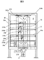
まず、図1から図3を参照しながら冷蔵庫全体に関して説明する。図1は本実施形態の冷蔵庫の正面図、図2は図1の冷蔵庫のA−A断面図、図3は図1の冷蔵庫本体の正面図である。   First, the whole refrigerator will be described with reference to FIGS. 1 is a front view of the refrigerator of the present embodiment, FIG. 2 is a cross-sectional view taken along the line AA of the refrigerator of FIG. 1, and FIG. 3 is a front view of the refrigerator body of FIG.

冷蔵庫1の庫内と庫外は、発泡ウレタンの発泡断熱材を充填することにより形成された断熱箱体10と,後述する扉12〜15によって隔てられている。冷蔵庫1の断熱箱体10の内部には複数の真空断熱材11を実装している。   The inside of the refrigerator 1 and the outside of the refrigerator are separated by a heat insulating box 10 formed by filling a foam heat insulating material of urethane foam and doors 12 to 15 described later. A plurality of vacuum heat insulating materials 11 are mounted inside the heat insulating box 10 of the refrigerator 1.

冷蔵庫1は,上から冷蔵室2、冷凍室3,4、野菜室5の順に複数の貯蔵室を有している。換言すれば、最上段に冷蔵室2が、最下段に野菜室5が、それぞれ区画して配置されており、冷蔵室2と野菜室5との間には、これらの両室と断熱的に仕切られた冷凍室3,4が配設されている。冷蔵室2及び野菜室5は冷蔵温度帯の貯蔵室であり、冷凍室3,4は、0℃以下の冷凍温度帯(例えば、約−20℃〜−18℃の温度帯)の貯蔵室である。なお、冷凍室3は製氷室3aと上段冷凍室3bとに区画されている。これらの貯蔵室は仕切り壁17,18,19により区画されている。   The refrigerator 1 has a plurality of storage rooms in the order of the refrigerator compartment 2, the freezer compartments 3 and 4, and the vegetable compartment 5 from the top. In other words, the refrigerator compartment 2 is arranged at the uppermost stage, and the vegetable compartment 5 is arranged at the lowermost stage, and between the refrigerator compartment 2 and the vegetable compartment 5, the two rooms are insulated from each other. Partitioned freezer compartments 3 and 4 are provided. The refrigerator compartment 2 and the vegetable compartment 5 are storage compartments in a refrigeration temperature zone, and the freezer compartments 3 and 4 are storage compartments in a freezing temperature zone of 0 ° C. or less (for example, a temperature zone of about −20 ° C. to −18 ° C.). is there. The freezer compartment 3 is divided into an ice making chamber 3a and an upper freezer compartment 3b. These storage rooms are partitioned by partition walls 17, 18 and 19.

冷蔵庫1の前面には、貯蔵室2〜5の前面開口部を閉塞する扉12〜15が設けられている。冷蔵室扉12は冷蔵室2の前面開口部を閉塞する扉、製氷室扉13aは製氷室3aの前面開口部を閉塞する扉、上段冷凍室扉13bは上段冷凍室3bの前面開口部を閉塞する扉、下段冷凍室扉14は下段冷凍室4の前面開口部を閉塞する扉、野菜室扉15は野菜室5の前面開口部を閉塞する扉である。冷蔵室扉12は観音開き式の両開きの扉で構成され、左側扉12a,右側扉12bとで構成される。製氷室3a,上段冷凍室3b,下段冷凍室4,野菜室5は、引き出し式の扉によって構成され、引き出し扉とともに貯蔵室内の容器が引き出される。   On the front surface of the refrigerator 1, doors 12 to 15 that close the front opening portions of the storage chambers 2 to 5 are provided. The refrigerator door 12 closes the front opening of the refrigerator compartment 2, the ice making door 13a closes the front opening of the ice making chamber 3a, and the upper freezer door 13b closes the front opening of the upper freezer 3b. The lower freezer compartment door 14 is a door for closing the front opening of the lower freezer compartment 4, and the vegetable compartment door 15 is a door for closing the front opening of the vegetable compartment 5. The refrigerator compartment door 12 is composed of a double door with double doors, and is composed of a left door 12a and a right door 12b. The ice making room 3a, the upper freezing room 3b, the lower freezing room 4, and the vegetable room 5 are constituted by a drawer-type door, and a container in the storage room is pulled out together with the drawer door.

冷蔵庫1には、冷凍サイクルが設置されている。この冷凍サイクルは、圧縮機60,凝縮器(図示せず),キャピラリチューブ(図示せず)及び冷却器70、そして再び圧縮機60の順に接続して構成されている。圧縮機60及び凝縮器は冷蔵庫本体1の背面下部に設けられた機械室6に設置されている。冷却器70は冷凍室3,4の後方に設けられた冷却器室7に設置され、この冷却器室7における冷却器70の上方に送風ファン71が設置されている。   The refrigerator 1 is provided with a refrigeration cycle. This refrigeration cycle is configured by connecting a compressor 60, a condenser (not shown), a capillary tube (not shown) and a cooler 70, and a compressor 60 in this order. The compressor 60 and the condenser are installed in a machine room 6 provided at the lower back of the refrigerator body 1. The cooler 70 is installed in a cooler chamber 7 provided behind the freezing chambers 3 and 4, and a blower fan 71 is installed above the cooler 70 in the cooler chamber 7.

冷却器70によって冷却された冷気は、送風ファン71によって冷蔵室2,製氷室3a,上段冷凍室3b,下段冷凍室4及び野菜室5の各貯蔵室へと送られる。具体的には、送風ファン71によって送られる冷気は、開閉可能なダンパ装置を介して、その一部が冷蔵室2及び野菜室5の冷蔵温度帯の貯蔵室へと送られ、他の一部が製氷室3a,上段冷凍室3b及び下段冷凍室4の冷凍温度帯の貯蔵室へと送られる。つまり、開閉可能なダンパ装置は、冷却室からの冷気を前記冷蔵温度帯の貯蔵室への冷蔵吐出口と前記冷凍温度帯の貯蔵室への冷凍吐出口の一方若しくは両方に選択可能に流通させる選択手段である。   The cold air cooled by the cooler 70 is sent by the blower fan 71 to the storage rooms of the refrigerator compartment 2, the ice making compartment 3 a, the upper freezer compartment 3 b, the lower freezer compartment 4, and the vegetable compartment 5. Specifically, a part of the cool air sent by the blower fan 71 is sent to the refrigerating temperature zone storage room of the refrigerating room 2 and the vegetable room 5 through a damper device that can be opened and closed, and the other part. Are sent to the storage room in the freezing temperature zone of the ice making room 3a, the upper freezing room 3b, and the lower freezing room 4. In other words, the openable / closable damper device allows the cold air from the cooling chamber to be selectively distributed to one or both of the refrigeration outlet to the storage compartment in the refrigeration temperature zone and the refrigeration outlet to the storage compartment in the refrigeration temperature zone. It is a selection means.

送風ファン71によって冷蔵室2,製氷室3a,上段冷凍室3b,下段冷凍室4及び野菜室5の各貯蔵室へと送られる冷気は、各貯蔵室を冷却した後、冷気戻り通路を通って冷却器室7へと戻される。このように、本実施形態の冷蔵庫は冷気の循環構造を有しており、各貯蔵室を適切な温度に維持する。   The cool air sent to the respective storage rooms of the refrigerator compartment 2, the ice making room 3a, the upper freezer compartment 3b, the lower freezer compartment 4 and the vegetable compartment 5 by the blower fan 71 passes through the cool air return passage after cooling each storage room. It is returned to the cooler chamber 7. Thus, the refrigerator of the present embodiment has a cold air circulation structure, and maintains each storage room at an appropriate temperature.

冷蔵室2内には、透明な板で構成される複数段の棚24a〜24eが取り外し可能に設置されている。最下段の棚24eは、断熱箱体10の背面及び両側面に接するように設置され、その下方空間である最下段空間21を上方空間と区画している。また、各冷蔵室扉12の内側には複数段の扉ポケット23a〜23cが設置され、これらの扉ポケット23a〜23cは冷蔵室扉12が閉じられた状態で冷蔵室2内に突出するように設けられている。   In the refrigerator compartment 2, a plurality of shelves 24a to 24e made of transparent plates are detachably installed. The lowermost shelf 24e is installed so as to be in contact with the back surface and both side surfaces of the heat insulation box 10, and partitions the lowermost space 21 which is the lower space from the upper space. A plurality of door pockets 23a to 23c are installed inside each refrigerator compartment door 12, and these door pockets 23a to 23c project into the refrigerator compartment 2 with the refrigerator compartment door 12 closed. Is provided.

冷蔵室2の背面には、送風ファン71から供給された冷気を通す通路を形成する背面パネル20が設けられている。さらに背面パネル20内には、冷蔵室2内に形成された空間に冷気を供給する、上下方向へ延びる冷蔵室冷気ダクトが設けられている。そして、この冷蔵室冷気ダクトは、左右に並べて設けられた、第一の冷蔵室冷気ダクト21と、第二の冷蔵室冷気ダクト22と、で構成されている。そして、第二の冷蔵室冷気ダクト22が、第一の冷蔵室冷気ダクト21の上端よりも上方の分岐部22cから二つに分かれ、第一の冷蔵室冷気ダクト21と第二の冷蔵室冷気ダクト22との鉛直投影が一部重なるような構成となっている。   A back panel 20 that forms a passage through which cool air supplied from the blower fan 71 passes is provided on the back of the refrigerator compartment 2. Further, a refrigerating room cold air duct extending in the vertical direction is provided in the back panel 20 to supply cold air to a space formed in the refrigerating room 2. And this cold room cold air duct is comprised by the 1st cold room cold air duct 21 and the 2nd cold room cold air duct 22 which were provided along with right and left. And the 2nd refrigerator compartment cold air duct 22 is divided into two from the branch part 22c above the upper end of the 1st refrigerator compartment cold air duct 21, and the 1st refrigerator compartment cold air duct 21 and the 2nd refrigerator compartment cold air are divided. The vertical projection with the duct 22 is partially overlapped.

第一の冷蔵室冷気ダクト21は、第二の冷蔵室冷気ダクト22より奥行寸法が大きく、すなわち風路面積が大きく構成されており,冷気吐出口210a〜210dに連通し,主に各棚24a〜24e上の食品を冷却する冷気の風路である。第二の冷蔵室冷気ダクト22は、冷蔵室天井付近の冷気吐出口220a,220bに連通し,主に冷蔵室扉ポケット23a〜23c内の食品を冷却する冷気の風路である。冷蔵室冷気ダクト21と22の風路面積や吐出口数の差は,冷却する領域の広さにあわせ,各領域を均等に冷却するためのものである。   The first cold room cold air duct 21 has a larger depth dimension than the second cold room cold air duct 22, that is, has a larger air passage area, communicates with the cold air discharge ports 210a to 210d, and mainly each shelf 24a. A cold air path to cool food on ~ 24e. The second refrigerator compartment cool air duct 22 communicates with the cool air outlets 220a and 220b near the ceiling of the refrigerator compartment, and is a cool air passage mainly for cooling food in the refrigerator compartment door pockets 23a to 23c. The difference in the air passage area and the number of outlets of the cold-chamber cool air ducts 21 and 22 is to cool each region equally according to the size of the region to be cooled.

冷蔵室2は,冷蔵室2内の温度を検知する手段として,第一の温度センサ271を背面パネル20内の棚24d背面部に,第二の温度センサ272を冷蔵室扉12近くの冷蔵室天井部に備えており,それぞれ,冷蔵室下部奥と冷蔵室上部前部の温度を検知している。   As a means for detecting the temperature in the refrigerator compartment 2, the refrigerator compartment 2 has a first temperature sensor 271 on the back of the shelf 24d in the back panel 20 and a second temperature sensor 272 in the refrigerator compartment near the refrigerator compartment door 12. It is provided on the ceiling and detects the temperature at the bottom of the refrigerator compartment and at the front of the refrigerator compartment.

冷蔵室冷気ダクト21及び22の上流部にはそれぞれ,冷蔵室ダンパ270a及び270bが設けられており,温度センサ271と272で検知された温度を利用して,それぞれのダンパの開閉を制御し,冷蔵室冷気ダクト21と22の冷気風量を調節することで,冷蔵室2内の各領域を適切な温度に維持することができる。   Refrigerating room dampers 270a and 270b are provided upstream of the refrigerating room cooling air ducts 21 and 22, respectively, and the opening / closing of each damper is controlled using the temperatures detected by the temperature sensors 271 and 272, respectively. By adjusting the amount of cool air in the refrigerator compartment cool air ducts 21 and 22, each region in the refrigerator compartment 2 can be maintained at an appropriate temperature.

次に,風路ダクトについて説明する。   Next, the air duct will be described.

図4は,冷蔵室冷気ダクト21及び22の背面斜視図である。図4に示すように,第二の冷蔵室冷気ダクト22は,上流部はストレート形状であり,下流部は,上流側から順に,湾曲部22a,ストレート部22b,分岐部22cを有する。さらにこの第二の冷蔵室冷気ダクト22は、分岐部22cで2つに分岐しつつ連続的な風路壁面により互いに独立して形成された風路と、それぞれの下流側で連通される冷気吐出口220a及び220bとを有し,これらの冷気吐出口から冷気を吐出する構造となっている。冷蔵室2内をバランス良く冷却する為には,この分岐形状を工夫して,冷気吐出口220aと220bに均等に冷気を分配する必要がある。   FIG. 4 is a rear perspective view of the refrigerator compartment cool air ducts 21 and 22. As shown in FIG. 4, the second refrigerating room cool air duct 22 has a straight shape in the upstream portion, and the downstream portion has a curved portion 22 a, a straight portion 22 b, and a branch portion 22 c in order from the upstream side. Further, the second refrigerating room cool air duct 22 is divided into two at the branch portion 22c, and the cool air discharge communicated on the downstream side with the air passage formed independently by the continuous air passage wall surface. It has outlets 220a and 220b, and has a structure for discharging cool air from these cool air discharge ports. In order to cool the inside of the refrigerator compartment 2 in a well-balanced manner, it is necessary to devise this branch shape and distribute the cool air evenly to the cool air discharge ports 220a and 220b.

図5は,冷蔵室冷気ダクト21及び22の背面の分岐部22c周辺の拡大図であり,図5中の点線Pは第二の冷蔵室冷気ダクト22の分岐部22cの分岐点の鉛直中心線である。図6は上から,図5のB−B断面図,図5のF−F断面図であり,それぞれ,第二の冷蔵室冷気ダクト22の湾曲前の風路断面,分岐部22cの分岐点の風路断面を示している。   FIG. 5 is an enlarged view of the vicinity of the branch portion 22c on the back surface of the cold room cool air ducts 21 and 22, and the dotted line P in FIG. 5 is the vertical center line of the branch point of the branch portion 22c of the second cold room cool air duct 22 It is. 6 is a cross-sectional view taken along the line BB in FIG. 5 and a cross-sectional view taken along the line FF in FIG. 5 from above, respectively, the cross-section of the air path before the bending of the second cold room cool air duct 22 and the branch point of the branch portion 22c. The cross section of the air path is shown.

冷蔵室冷気ダクト21及び22の表面に組み付けられている背面パネル20の表面は,半楕円形状に近い,なめらかな曲面をなしている。この形状により,外観の意匠性向上に加えて,棚24a〜24eの食品収納スペースを広くとり,使用者が収納した食品を見やすく,出し入れがしやすい,使いやすい構造とすることができる。   The surface of the back panel 20 assembled on the surfaces of the cold room cool air ducts 21 and 22 has a smooth curved surface close to a semi-elliptical shape. With this shape, in addition to improving the design of the appearance, the food storage space of the shelves 24a to 24e can be widened so that the food stored by the user can be easily seen and put in and out.

冷蔵室冷気ダクト21及び22は外表面が背面パネル20の曲面に沿った形状となっており,背面パネル20と箱体10の間の空間で必要な断熱厚を保ったうえで,最大限風路を広くとれる構造となっている。さらに左右方向で冷蔵室冷気ダクト21と22を区切っているため,図6のA−A断面図に示すように,第二の冷蔵室冷気ダクト22は第一の冷蔵室冷気ダクト21と隣接する上流部で左右非対称な形状を有している。   The refrigeration chamber cool air ducts 21 and 22 have outer surfaces that follow the curved surface of the rear panel 20, and maintain the necessary heat insulation thickness in the space between the rear panel 20 and the box 10, and maximize the wind It has a structure that can take a wide road. Further, since the refrigerator compartment cool air ducts 21 and 22 are separated in the left-right direction, the second refrigerator compartment cool air duct 22 is adjacent to the first refrigerator compartment cool air duct 21 as shown in the AA sectional view of FIG. It has an asymmetric shape in the upstream part.

図7は,上から,図5のC−C断面図,図5のD−D断面図,図5のE−E断面図であり,それぞれ,湾曲部22a上流側,湾曲部22a下流側,ストレート部22bの風路断面を示している。また,図8は図5のG−G断面図であり,分岐後の風路断面を示している。   7 is a cross-sectional view taken along the line CC in FIG. 5, a cross-sectional view taken along the line DD in FIG. 5, and a cross-sectional view taken along the line EE in FIG. 5 from above, respectively. The air path cross section of the straight part 22b is shown. FIG. 8 is a cross-sectional view taken along the line G-G in FIG.

第二の冷蔵室冷気ダクト22内を流れる冷気は、湾曲部22aの部分で右側へ移動させるような力を受けるため、第二の冷蔵室冷気ダクト22内の左側の冷気は、分岐部22cから右側の冷気吐出口220aへ流入し易い。そこで、図5に点線Pで示すように,第二の冷蔵室冷気ダクト22の分岐点Pが,湾曲する前の右側風路壁面25aより右側に位置するように構成した。これにより、第二の冷蔵室冷気ダクト22内の右側の多くの冷気が、そのまま上方へ直進して分岐部22cから左側の冷気吐出口220bへ流入し易くなる。その結果、第二の冷蔵室冷気ダクト22を上方で右側へ湾曲させた場合であっても、分岐部22cから左右の冷気吹出口へ向けて、冷気の偏りを抑制し、冷気をバランス良く分配できる。   Since the cold air flowing in the second cold room cold air duct 22 receives a force that moves to the right side at the curved portion 22a, the left cold air in the second cold room cold air duct 22 flows from the branch portion 22c. It tends to flow into the cool air outlet 220a on the right side. Therefore, as indicated by a dotted line P in FIG. 5, the branch point P of the second refrigerating room cold air duct 22 is configured to be located on the right side of the right air channel wall surface 25a before being bent. As a result, a large amount of the cool air on the right side in the second refrigerating room cool air duct 22 goes straight upward and easily flows from the branch portion 22c to the left cool air discharge port 220b. As a result, even when the second refrigeration room cold air duct 22 is bent upward and to the right, the cold air is prevented from being biased from the branch portion 22c to the left and right cold air outlets, and the cold air is distributed in a balanced manner. it can.

また,図6のA−A断面図に示すように,冷蔵室冷気ダクト22の風路は,右側ほど風路の奥行きが大きく,断面積が広くなっていく。そのため,冷蔵室冷気ダクト22上流部を流れる冷気は,右側風路壁面25a付近の流量が最も大きい。分岐点Pが,湾曲する前の右側風路壁面25aより右側にくるような構成とすることで,流量の大きい右側風路壁面25a付近の冷気が直進して分岐部22cから左側へ流入し易くなる。このため、湾曲部22aによって冷気が右側へ偏り易い構造であっても、左右へ均等な風量分配が可能となる。   Further, as shown in the AA cross-sectional view of FIG. 6, the air path of the refrigerator compartment cold air duct 22 has a greater depth and a larger cross-sectional area toward the right side. Therefore, the cold air flowing in the upstream portion of the cold room cold air duct 22 has the largest flow rate in the vicinity of the right-side air channel wall surface 25a. By adopting a configuration in which the branch point P is located on the right side of the right-side air channel wall surface 25a before being bent, the cold air near the right-side air channel wall surface 25a having a large flow rate goes straight and easily flows from the branch part 22c to the left side. Become. For this reason, even if it is a structure where the cold air is easily biased to the right side by the curved portion 22a, it is possible to distribute the air volume evenly to the left and right.

図7に示すように,冷蔵室冷気ダクト22の風路は、湾曲部上流から下流に向かうに連れて,風路が右側に傾くと共に,左側の奥行寸法が徐々に大きくなってゆく。このため、風路断面が左右対称に近づいてゆき,ストレート部22bでは左右対称な形状を成している。これによって,冷気の風量の偏りも小さくなっていく。   As shown in FIG. 7, the air path of the cold room cool air duct 22 is inclined to the right side and the depth dimension on the left side gradually increases as it goes from the upstream side to the downstream side of the curved portion. For this reason, the cross section of the air passage approaches the left-right symmetry, and the straight portion 22b has a symmetrical shape. As a result, the deviation of the air volume of the cold air is also reduced.

第二の冷蔵室冷気ダクト22は,右側へ湾曲してから分岐部22cへ至る間に,ストレート部22bを有している。これは,逆に,湾曲部22aで冷気が右側へ傾いて進むため,分岐点で冷気が直進方向にある右側に偏って分配されてしまうことを防ぐためである。   The second refrigerating room cool air duct 22 has a straight portion 22b between the right side of the refrigeration chamber cold air duct 22 and the branch portion 22c. On the contrary, the cold air is inclined to the right side at the bending portion 22a, and therefore, the cold air is prevented from being distributed to the right side in the straight direction at the branch point.

湾曲部22aで風路断面内の偏りを解消した冷気の流れは,ストレート部22bで流れの方向を鉛直上向きに修正し,分岐部22cに到達する。分岐部22cでは冷気の風量の偏りが小さく,進行方向も鉛直上向きにあるため,均等に冷気が分岐され,冷気吐出口220a,220bからバランス良く冷気を吐出,冷蔵室2内に供給することができる。   The flow of the cold air in which the deviation in the cross section of the air passage is eliminated by the curved portion 22a, the flow direction is corrected vertically upward by the straight portion 22b, and reaches the branching portion 22c. In the branch part 22c, the deviation of the air volume of the cold air is small and the traveling direction is also vertically upward, so that the cold air is evenly branched, and cool air is discharged from the cold air discharge ports 220a and 220b in a well-balanced manner and supplied into the refrigerator compartment 2. it can.

したがって,本実施例によれば,食品収納スペースを広く確保しながら,吐出口からバランス良く冷気を分配することで,庫内の温度ムラを小さく抑えた冷蔵庫を提供することができる。なお、本実施例では、第二の冷蔵室冷気ダクト22は、右側が左側よりも奥行寸法が大きく、下流側(上方)で右側へ湾曲した後に分岐部に至る構成(図5参照)となっているが、左右方向について逆の構成であっても良い。   Therefore, according to the present embodiment, it is possible to provide a refrigerator in which the temperature unevenness in the refrigerator is kept small by distributing cold air in a balanced manner from the discharge port while ensuring a wide food storage space. In the present embodiment, the second refrigerator compartment cooler air duct 22 has a configuration in which the right side has a depth dimension larger than the left side and curves to the right side on the downstream side (upward) and then reaches the branch (see FIG. 5). However, the configuration may be reversed in the left-right direction.

1 冷蔵庫
2 冷蔵室
3a 製氷室
3b 上段冷凍室
4 下段冷凍室
5 野菜室
6 機械室
7 冷却器室
10 断熱壁
11 真空断熱材
12a 冷蔵室扉左
12b 冷蔵室扉右
13a 製氷室扉
13b 上段冷凍室扉
14 下段冷凍室扉
15 野菜室扉
17 冷蔵室−冷凍室間仕切り
18 冷凍室内仕切り
19 冷凍室−野菜室間仕切り
20 冷蔵室背面パネル
21 第一の冷蔵室冷気ダクト
22 第二の冷蔵室冷気ダクト
22a 第二の冷蔵室冷気ダクトの湾曲部
22b 第二の冷蔵室冷気ダクトのストレート部
22c 第二の冷蔵室冷気ダクト分岐部
23 冷蔵室扉ポケット
24 冷蔵室棚
25 第二の冷蔵室冷気ダクト風路壁面
40 脱臭部材
60 圧縮機
70 冷却器
71 冷却ファン
210 第一の冷気吐出口
211 第二の冷気吐出口
270 冷蔵室ダンパ
271 第一の冷蔵室温度センサ
272 第二の冷蔵室温度センサ
DESCRIPTION OF SYMBOLS 1 Refrigerator 2 Refrigerating room 3a Ice making room 3b Upper freezing room 4 Lower freezing room 5 Vegetable room 6 Machine room 7 Cooler room 10 Heat insulation wall 11 Vacuum heat insulating material 12a Refrigerating room door left 12b Refrigerating room door right 13a Ice making room door 13b Upper freezing Room door 14 Lower refrigeration room door 15 Vegetable room door 17 Refrigeration room-freezer compartment partition 18 Freezer compartment partition 19 Freezer compartment-vegetable compartment partition 20 Refrigerator back panel 21 First refrigeration compartment cold air duct 22 Second refrigeration compartment cold air duct 22a Curved portion of the second cold room cold air duct 22b Straight portion of the second cold room cold air duct 22c Second cold room cold air duct branching portion 23 Cold room door pocket 24 Cold room shelf 25 Second cold room cold air duct wind Road wall surface 40 Deodorizing member 60 Compressor 70 Cooler 71 Cooling fan 210 First cold air discharge port 211 Second cold air discharge port 270 271 first of the refrigerating compartment temperature sensor 272 second refrigerating compartment temperature sensor

Claims (3)

冷蔵温度帯の貯蔵室と、前記貯蔵室内に形成された空間に冷気を供給する上下へ延びる冷気ダクトと、を備え、前記冷気ダクトは、左右方向の一方側に配置される第一の冷気ダクトと、左右方向の他方側に配置される第二の冷気ダクトと、を有する冷蔵庫において、A first cold air duct disposed on one side in the left-right direction, and a cold air duct extending vertically to supply cold air to a space formed in the storage room. And a second cold air duct disposed on the other side in the left-right direction,
前記第二の冷気ダクトは、前記第一の冷気ダクトの上端よりも下方から前記一方側へ湾曲し、前記第一の冷気ダクトの上端よりも上方にあって鋭角をなす部分の頂点付近である分岐部から2つに分かれ、  The second cold air duct is curved from the lower end to the one side from the upper end of the first cold air duct, and is near the apex of the portion that is above the upper end of the first cold air duct and forms an acute angle. Divided into two from the branch,
前記第一の冷気ダクトと前記第二の冷気ダクトとは、鉛直投影が少なくとも一部重なり、  The first cold air duct and the second cold air duct have at least partly overlapping vertical projections,
前記第二の冷気ダクトの上流側における前記一方側の風路壁面が、前記分岐部よりも前記他方側に位置することを特徴とする冷蔵庫。  The refrigerator, wherein the one-side air passage wall surface on the upstream side of the second cold air duct is located on the other side with respect to the branch portion.
前記第二の冷気ダクトは、前記一方側へ湾曲してから前記分岐部へ至る間に、ストレート部を有する請求項1に記載の冷蔵庫。 The refrigerator according to claim 1, wherein the second cold air duct has a straight portion between the second cold air duct and the branch portion after being bent toward the one side. 前記第二の冷気ダクトは、前記一方側へ湾曲する部分で,前記他方側の奥行寸法が徐々に大きくなることを特徴とする請求項1または2に記載の冷蔵庫。 The refrigerator according to claim 1 or 2, wherein the second cold air duct is a portion that curves to the one side, and a depth dimension of the other side gradually increases.
JP2015156599A 2015-08-07 2015-08-07 refrigerator Active JP6567918B2 (en)

Priority Applications (1)

Application Number Priority Date Filing Date Title
JP2015156599A JP6567918B2 (en) 2015-08-07 2015-08-07 refrigerator

Applications Claiming Priority (1)

Application Number Priority Date Filing Date Title
JP2015156599A JP6567918B2 (en) 2015-08-07 2015-08-07 refrigerator

Publications (2)

Publication Number Publication Date
JP2017036851A JP2017036851A (en) 2017-02-16
JP6567918B2 true JP6567918B2 (en) 2019-08-28

Family

ID=58049283

Family Applications (1)

Application Number Title Priority Date Filing Date
JP2015156599A Active JP6567918B2 (en) 2015-08-07 2015-08-07 refrigerator

Country Status (1)

Country Link
JP (1) JP6567918B2 (en)

Families Citing this family (2)

* Cited by examiner, † Cited by third party
Publication number Priority date Publication date Assignee Title
JP7097996B2 (en) * 2019-01-08 2022-07-08 三菱電機株式会社 Ducts and refrigerators
CN111912153A (en) * 2019-05-10 2020-11-10 青岛海尔电冰箱有限公司 Refrigerating and freezing device

Family Cites Families (3)

* Cited by examiner, † Cited by third party
Publication number Priority date Publication date Assignee Title
JP3026314B2 (en) * 1991-08-30 2000-03-27 松下冷機株式会社 refrigerator
JP5909427B2 (en) * 2012-08-23 2016-04-26 日立アプライアンス株式会社 refrigerator
JP6165427B2 (en) * 2012-08-27 2017-07-19 日立アプライアンス株式会社 refrigerator

Also Published As

Publication number Publication date
JP2017036851A (en) 2017-02-16

Similar Documents

Publication Publication Date Title
JP2009063245A (en) Refrigerator
JP5436522B2 (en) Freezer refrigerator
US10107544B2 (en) Refrigerator providing air flow to door
JP6567918B2 (en) refrigerator
JP6157903B2 (en) refrigerator
CN103827607B (en) Freezer
JP6405526B2 (en) refrigerator
KR20130016987A (en) Refrigerator mounted with cooling shelf
JP2021076296A (en) refrigerator
JP6389075B2 (en) refrigerator
KR102147213B1 (en) Refrigerator
JP6584674B2 (en) refrigerator
KR20110089575A (en) Refrigerator
JP2014167361A (en) Refrigerator
JP2019027650A (en) refrigerator
JP6954605B2 (en) refrigerator
JP2014134332A (en) Refrigerator
JP6496630B2 (en) refrigerator
JP4630849B2 (en) refrigerator
JP7029158B2 (en) refrigerator
JP5553799B2 (en) refrigerator
JP2019020004A (en) refrigerator
JP6865349B2 (en) refrigerator
JP2016090073A (en) refrigerator
WO2020125451A1 (en) Refrigerator

Legal Events

Date Code Title Description
A521 Written amendment

Free format text: JAPANESE INTERMEDIATE CODE: A523

Effective date: 20150817

RD04 Notification of resignation of power of attorney

Free format text: JAPANESE INTERMEDIATE CODE: A7424

Effective date: 20170119

RD04 Notification of resignation of power of attorney

Free format text: JAPANESE INTERMEDIATE CODE: A7424

Effective date: 20170125

A621 Written request for application examination

Free format text: JAPANESE INTERMEDIATE CODE: A621

Effective date: 20180215

A521 Written amendment

Free format text: JAPANESE INTERMEDIATE CODE: A523

Effective date: 20180216

A977 Report on retrieval

Free format text: JAPANESE INTERMEDIATE CODE: A971007

Effective date: 20181219

A131 Notification of reasons for refusal

Free format text: JAPANESE INTERMEDIATE CODE: A131

Effective date: 20181225

A521 Written amendment

Free format text: JAPANESE INTERMEDIATE CODE: A523

Effective date: 20190225

TRDD Decision of grant or rejection written
A01 Written decision to grant a patent or to grant a registration (utility model)

Free format text: JAPANESE INTERMEDIATE CODE: A01

Effective date: 20190702

A61 First payment of annual fees (during grant procedure)

Free format text: JAPANESE INTERMEDIATE CODE: A61

Effective date: 20190801

R150 Certificate of patent or registration of utility model

Ref document number: 6567918

Country of ref document: JP

Free format text: JAPANESE INTERMEDIATE CODE: R150