JP6567916B2 - Coupling device - Google Patents
Coupling device Download PDFInfo
- Publication number
- JP6567916B2 JP6567916B2 JP2015154566A JP2015154566A JP6567916B2 JP 6567916 B2 JP6567916 B2 JP 6567916B2 JP 2015154566 A JP2015154566 A JP 2015154566A JP 2015154566 A JP2015154566 A JP 2015154566A JP 6567916 B2 JP6567916 B2 JP 6567916B2
- Authority
- JP
- Japan
- Prior art keywords
- valve
- joint
- casing
- valve seat
- diameter portion
- Prior art date
- Legal status (The legal status is an assumption and is not a legal conclusion. Google has not performed a legal analysis and makes no representation as to the accuracy of the status listed.)
- Active
Links
- 230000008878 coupling Effects 0.000 title claims description 26
- 238000010168 coupling process Methods 0.000 title claims description 26
- 238000005859 coupling reaction Methods 0.000 title claims description 26
- 230000002093 peripheral effect Effects 0.000 claims description 36
- 239000012530 fluid Substances 0.000 claims description 22
- 238000007789 sealing Methods 0.000 claims description 14
- 230000007257 malfunction Effects 0.000 description 7
- 238000004891 communication Methods 0.000 description 5
- 230000004308 accommodation Effects 0.000 description 2
- 230000000694 effects Effects 0.000 description 2
- 239000007788 liquid Substances 0.000 description 2
- 239000000470 constituent Substances 0.000 description 1
- 238000012986 modification Methods 0.000 description 1
- 230000004048 modification Effects 0.000 description 1
Images


Landscapes
- Quick-Acting Or Multi-Walled Pipe Joints (AREA)
Description
この発明は、第1継手および第2継手に形成された給排路を分離可能に接続するカップリング装置に関する。 The present invention relates to a coupling device that detachably connects supply and discharge paths formed in a first joint and a second joint.
この種のカップリング装置には、従来では、特許文献1(日本国・実用新案登録第3179484号公報)に記載されたものがある。その従来技術は、次のように構成されている。
固定側のクランプパレットに第1継手が設けられると共に、可動側のワークパレットに第2継手が設けられる。その第1継手の第1ケーシングに弁ケースが挿入され、その弁ケース内に第1弁部材が挿入される。第1ケーシング内に設けられた駆動手段によって弁ケースと第1弁部材とが昇降される。その弁ケースと第1弁部材との間に第1弁機構が設けられ、その第1弁機構が第1ケーシング内の第1給排路を開閉する。また、第2継手の第2ケーシングに第2弁部材が挿入される。その第2ケーシングと第2弁部材との間に第2弁機構が設けられ、その第2弁機構が第2ケーシング内の第2給排路を開閉する。上記第1継手と第2継手とを連結させるときには、第1継手と第2継手とを突き合わせた状態で、駆動手段によって弁ケースと第1弁部材とを上昇させる。すると、弁ケースが第2ケーシングに受け止められる共に、第1弁部材が第2弁部材を第2ケーシング内に後退させ第1弁機構及び第2弁機構が開弁される。Conventionally, this type of coupling apparatus is described in Patent Document 1 (Japanese Utility Model Registration No. 3179484). The prior art is configured as follows.
The first joint is provided on the clamp pallet on the fixed side, and the second joint is provided on the work pallet on the movable side. A valve case is inserted into the first casing of the first joint, and a first valve member is inserted into the valve case. The valve case and the first valve member are moved up and down by driving means provided in the first casing. A first valve mechanism is provided between the valve case and the first valve member, and the first valve mechanism opens and closes the first supply / discharge path in the first casing. Further, the second valve member is inserted into the second casing of the second joint. A second valve mechanism is provided between the second casing and the second valve member, and the second valve mechanism opens and closes the second supply / discharge path in the second casing. When connecting the first joint and the second joint, the valve case and the first valve member are raised by the driving means in a state where the first joint and the second joint are abutted. Then, the valve case is received by the second casing, and the first valve member retracts the second valve member into the second casing, and the first valve mechanism and the second valve mechanism are opened.
上記の従来技術は次の問題がある。
上記第1継手と第2継手とが離間された状態で、駆動手段の誤作動や誤操作によって弁ケースと第1弁部材とを上昇させることがある。このときに、弁ケースが第1ケーシングに受け止められる共に、第1弁部材が弁ケースから離間されて第1弁機構が開弁される。その結果、第1弁機構の開弁隙間から第1給排路の圧力流体が外部へ流出される。
本発明の目的は、第1継手と第2継手とが離間された状態であって、何らかの原因(例えば、駆動手段が誤作動したり誤操作されたりすること)によって、第1継手内の圧力流体が外部に流出しないカップリング装置を提供することにある。The above prior art has the following problems.
In a state where the first joint and the second joint are separated from each other, the valve case and the first valve member may be raised by a malfunction or erroneous operation of the drive means. At this time, the valve case is received by the first casing, the first valve member is separated from the valve case, and the first valve mechanism is opened. As a result, the pressure fluid in the first supply / discharge path flows out from the valve opening gap of the first valve mechanism.
An object of the present invention is a state in which the first joint and the second joint are separated from each other, and the pressure fluid in the first joint is caused by some cause (for example, the drive means malfunctions or misoperates). Is to provide a coupling device that does not flow out to the outside.
上記の目的を達成するため、第1の発明は、例えば、図1から図3に示すように、カップリング装置を次のように構成した。
カップリング装置は、第1継手5と、その第1継手5に着脱自在に先端側から接続される第2継手6とを備える。前記第1継手5内に設けられた第1給排路7と第2継手内6に設けられた第2給排路8とを分離可能に接続する。前記第1継手5が第1ケーシング10を有し、その第1ケーシング10内に筒状の弁ケース15が軸心方向に移動可能で保密状に挿入される。前記第1ケーシング10内に設けられた駆動手段Dが、前記弁ケース15を先端側へ進出および基端側へ後退させる。前記弁ケース15の先端部分に第1弁座21が設けられる。前記弁ケース15内に軸心方向に第1弁部材25が移動可能に挿入される。その第1弁部材25が、前記第1弁座21に基端側から当接される第1弁面27を有する。第1付勢手段28が前記第1弁面27を前記第1弁座21に向けて付勢する。前記第2継手6が第2ケーシング40を有し、その第2ケーシング40に弁座部材42が設けられる。その弁座部材42が第2弁座43を有する。前記第2ケーシング40内に筒状の第2弁部材45が軸心方向に移動可能で保密状に挿入される。その第2弁部材45が、第2弁座43に先端側から当接される第2弁面46を有する。第2付勢手段47が前記第2弁面46を前記第2弁座43に向けて付勢する。In order to achieve the above object, according to the first invention, for example, as shown in FIGS. 1 to 3, the coupling device is configured as follows.
The coupling device includes a
第1の発明は次の作用効果を奏する。
前記第1継手と前記第2継手とを接続する場合には、まず、第2継手の第2弁部材が第1継手の弁部材に先端側から当接される。次いで、前記駆動手段が弁ケースを介して第2弁部材を第2ケーシング内に後退させると共に、前記弁座部材が第1弁部材を弁ケースに対して基端側へ移動させる。これにより、第2弁面が第2弁座から離間されて開弁されると共に、第1弁面が第1弁座から離間されて開弁される。その結果、前記第1給排路と第2給排路とが接続される。
前記第1継手と前記第2継手とを分離する場合には、前記駆動手段が前記弁ケースを基端側へ後退させる。すると、第2付勢手段が第2弁部材を弁座部材に向けて移動させると共に第1付勢手段が第1弁部材を弁ケースに向けて移動させる。これにより、第2弁面が第2弁座に当接して閉弁されると共に、第1弁面が第1弁座に当接して閉弁される。その結果、前記第2給排路と第1給排路とが分離される。
上記の第1継手と第2継手とが離間された状態で、何らかの原因、例えば、駆動手段が誤作動したり誤操作されたりすることにより、弁ケースが先端側へ移動されることがある。このような場合でも、第1付勢手段が第1弁体を第1弁座に当接させて閉弁状態が維持されている。その結果、第1給排路に供給された流体が、第1弁体と第1弁座との間から外部に流出するのを防止できる。The first invention has the following effects.
When connecting the first joint and the second joint, first, the second valve member of the second joint is brought into contact with the valve member of the first joint from the distal end side. Next, the drive means moves the second valve member back into the second casing through the valve case, and the valve seat member moves the first valve member to the proximal side with respect to the valve case. As a result, the second valve surface is opened away from the second valve seat, and the first valve surface is opened away from the first valve seat. As a result, the first supply / discharge path and the second supply / discharge path are connected.
When separating the first joint and the second joint, the driving means moves the valve case backward to the proximal end side. Then, the second urging means moves the second valve member toward the valve seat member, and the first urging means moves the first valve member toward the valve case. As a result, the second valve surface comes into contact with the second valve seat and closes, and the first valve surface comes into contact with the first valve seat and closes. As a result, the second supply / discharge path and the first supply / discharge path are separated.
In a state where the first joint and the second joint are separated from each other, the valve case may be moved to the distal end side due to some cause, for example, when the driving means malfunctions or is erroneously operated. Even in such a case, the first urging means brings the first valve body into contact with the first valve seat and the valve closed state is maintained. As a result, it is possible to prevent the fluid supplied to the first supply / discharge path from flowing out between the first valve body and the first valve seat.
第1の発明は、下記の構成を加えることが好ましい。
(1)前記駆動手段Dがリリースバネ20を備える。そのリリースバネ20が前記第1ケーシング10内に装着されると共に、前記弁ケース15を基端側に向けて付勢する。
この場合、リリースバネが弁ケースを基端側へ確実に後退させる。The first invention preferably adds the following configuration.
(1) The driving means D includes a
In this case, the release spring reliably retracts the valve case to the proximal end side.
(2)前記第1給排路7の圧力流体の圧力が先端方向へ作用する前記弁ケース15の受圧面積Aは、前記弁ケース15と前記第2弁部材45とが当接されることにより封止される部分の内側の受圧面積Bよりも大きく設定されている。また、前記第2給排路8の圧力流体の圧力が基端方向へ作用する前記第2弁部材45の受圧面積Cは、上記の受圧面積Bよりも大きく設定されている。さらに、上記の受圧面積Aは、上記の受圧面積Cよりも大きく設定されている。
この場合、受圧面積Aが受圧面積Bよりも大きく設定されているので、第1給排路に供給された圧力流体が第1弁部材を先端側へ押圧する。また、受圧面積Cが受圧面積Bよりも大きく設定されているので、第2給排路に供給された圧力流体が、第2弁部材を基端側へ押圧する。さらに、受圧面積Aが受圧面積Cよりも大きく設定されているので、第1給排路および第2給排路に供給された圧力流体が、第1弁ケースを先端側へ押す力が、第1給排路および第2給排路に供給された圧力流体が、第2弁部材を基端側へ押す力よりも大きくなる。その結果、第1給排路および第2給排路に供給された圧力流体が、第2弁部材の封止部材を弁ケースに向けて確実に押圧させる。(2) The pressure receiving area A of the
In this case, since the pressure receiving area A is set to be larger than the pressure receiving area B, the pressure fluid supplied to the first supply / discharge path presses the first valve member toward the distal end side. Further, since the pressure receiving area C is set larger than the pressure receiving area B, the pressure fluid supplied to the second supply / discharge path presses the second valve member toward the base end side. Further, since the pressure receiving area A is set to be larger than the pressure receiving area C, the pressure fluid supplied to the first supply / discharge path and the second supply / discharge path pushes the first valve case toward the distal end side. The pressure fluid supplied to the first supply / discharge passage and the second supply / discharge passage becomes larger than the force pushing the second valve member toward the proximal end. As a result, the pressure fluid supplied to the first supply / discharge passage and the second supply / discharge passage reliably presses the sealing member of the second valve member toward the valve case.
上記の目的を達成するため、第2の発明は、例えば、図4Aおよび図4Bに示すように、カップリング装置を次のように構成した。
カップリング装置は、第1継手5と、その第1継手5に着脱自在に先端側から接続される第2継手6とを備える。前記第1継手5内に設けられた第1給排路7と第2継手内6に設けられた第2給排路8とを分離可能に接続する。前記第1継手5は、第1ケーシング10を有し、その第1ケーシング10内に筒状の弁ケース15が軸心方向に移動可能で保密状に挿入される。前記第1ケーシング10内に設けられた駆動手段Dが、前記弁ケース15を先端側へ進出および基端側へ後退させる。前記弁ケース15に弁座部材56が設けられ、その弁座部材56の先端部分に第1弁座21が設けられる。前記弁ケース15内に第1弁部材25が軸心方向に移動可能に保密状に挿入され、その第1弁部材25が、前記第1弁座21に基端側から当接される第1弁面27を有する。第1付勢手段28が前記第1弁面27を前記第1弁座21に向けて付勢する。前記第2継手6は、第2ケーシング40を有し、その第2ケーシング40に第2弁座43が設けられる。前記第2ケーシング40内に筒状の第2弁部材45が軸心方向に移動可能で保密状に挿入され、その筒状の第2弁部材45が、前記第2弁座43に先端側から当接される第2弁面46を有する。第2付勢手段47が前記第2弁面46を前記第2弁座43に向けて付勢する。In order to achieve the above object, in the second invention, for example, as shown in FIGS. 4A and 4B, a coupling device is configured as follows.
The coupling device includes a
第2の発明は次の作用効果を奏する。
前記第1継手と前記第2継手とを接続する場合には、まず、第2継手の第2弁部材が第1継手の弁部材に先端側から当接される。次いで、前記駆動手段が弁ケースを介して第1弁部材を弁ケースに対して基端側へ移動させると共に、前記弁座部材が第2弁部材を第2ケーシングに対して先端側へ移動させる。これにより、第1弁面が第1弁座から離間されて開弁されると共に、第2弁面が第2弁座から離間されて開弁される。その結果、前記第1給排路と第2給排路とが接続される。
前記第1継手と前記第2継手とを分離する場合には、駆動手段が前記弁ケースを基端側へ後退させる。すると、第1付勢手段が第1弁体を第1弁座に向けて移動させると共に第2付勢手段が第2弁体を第2弁座に向けて移動させる。これにより、第1弁面が第1弁座に当接して閉弁されると共に、第2弁面が第2弁座に当接して閉弁される。その結果、前記第2給排路と第1給排路とが分離される。
上記の第1継手と第2継手とが離間された状態で、何らかの原因、例えば、駆動手段が誤作動したり誤操作されたりすることにより、弁ケースが先端側へ移動されることがある。このような場合でも、第1付勢手段が第1弁体を第1弁座に当接させて閉弁状態が維持されている。その結果、第1給排路に供給された流体が、第1弁体と第1弁座との間から外部に流出するのを防止できる。The second invention has the following effects.
When connecting the first joint and the second joint, first, the second valve member of the second joint is brought into contact with the valve member of the first joint from the distal end side. Next, the driving means moves the first valve member to the proximal end side with respect to the valve case via the valve case, and the valve seat member moves the second valve member to the distal end side with respect to the second casing. . As a result, the first valve surface is opened away from the first valve seat, and the second valve surface is opened away from the second valve seat. As a result, the first supply / discharge path and the second supply / discharge path are connected.
When separating the first joint and the second joint, the drive means moves the valve case backward to the proximal end side. Then, the first urging means moves the first valve body toward the first valve seat and the second urging means moves the second valve body toward the second valve seat. As a result, the first valve surface comes into contact with the first valve seat and closes, and the second valve surface comes into contact with the second valve seat and closes. As a result, the second supply / discharge path and the first supply / discharge path are separated.
In a state where the first joint and the second joint are separated from each other, the valve case may be moved to the distal end side due to some cause, for example, when the driving means malfunctions or is erroneously operated. Even in such a case, the first urging means brings the first valve body into contact with the first valve seat and the valve closed state is maintained. As a result, it is possible to prevent the fluid supplied to the first supply / discharge path from flowing out between the first valve body and the first valve seat.
以下、本発明の実施形態を説明する。
図1から図3は、本発明の第1実施形態を示し、まず、図1によってカップリング装置の構造を説明する。Embodiments of the present invention will be described below.
1 to 3 show a first embodiment of the present invention. First, the structure of a coupling device will be described with reference to FIG.
基準ブロックであるクランプパレット1に、可動ブロックであるワークパレット2が着脱自在に上方から装着される。本発明のカップリング装置は、前記クランプパレット1に装着された第1継手5と、前記ワークパレット2に装着された第2継手6とを有する。その第1継手5内に第1給排路7が形成されると共に、第2継手6内に第2給排路8が形成される。 A
上記クランプパレット1に第1継手5の第1ケーシング10がボルトによって固定される。その第1ケーシング10は、外筒11と、その外筒11の内周孔の下部に螺合される内筒12とを有する。その内筒12は、外筒11に保密状に螺合される大径部分12aと、その大径部分12aの上側に設けられた小径部分12bとを有する。小径部分12bと外筒11の内周孔との間に隙間が形成され、その隙間に弁ケース15の大径部分15aが封止部材12cを介して保密状で上下方向へ移動可能に挿入される。その大径部分15aの上側に小径部分15bが突設される。また、弁ケース15が駆動手段Dによって上下方向へ移動可能に挿入され、その駆動手段Dは、次のように構成される。 The
上記の外筒11の内周孔と内筒12の外周部と弁ケース15の大径部分15aとによってロック室16が区画形成される。そのロック室16は、外筒11に形成された連通路17と、クランプパレット1に形成された圧油(圧力流体)の給排路18とを介して圧油供給源(図示せず)に接続されている。また、弁ケース15の大径部分15aの上面と、第1ケーシング10の内周孔の上部に半径方向の内方に向けて突設された突出部分10aとの間にリリースバネ20が装着される。そのリリースバネ20が弁ケース15を下方へ後退させる。 A
上記の弁ケース15の上端部から突出部分15cが半径方向の内方へ突設される。その突出部分15cの内周壁に第1弁座21が上方へ向かうにつれて軸心に近づくように形成される。また、弁ケース15の小径部分15bの内周孔にリング状の案内部材22が止め輪23によって固定される。その案内部材22の内周孔に第1弁部材25の小径部分25aが上下方向に移動可能に挿入される。その第1弁部材25の小径部分25aの上側に大径部分25bが形成される。その大径部分25bの外周壁が、上方へ向かうにつれて軸心に近づくように形成されると共に、周方向に形成された溝26を有する。その溝26に封止部材が装着され、その封止部材の外周部に第1弁面27が形成される。 A protruding
上記の案内部材22と第1弁部材25の大径部分25aとの間に、第1閉弁バネ(第1付勢手段)28が装着され、その第1閉弁バネ28が第1弁部材25を弁ケース15の突出部分15cに向けて押圧している。このため、その第1弁面27が第1弁座21に当接している。 A first valve closing spring (first biasing means) 28 is mounted between the
上記の第1給排路7は、第1弁座21と第1弁面27との間に形成された開弁隙間と、弁ケース15の内周孔と、案内部材22に形成された連通孔29と、内筒12に形成された第1給排口30とによって構成される。 The first supply /
上記ワークパレット2に第2継手6の第2ケーシング40がボルトによって固定される。その第2ケーシング40に装着孔41が形成され、その装着孔41の底壁に弁座部材42が下方へ突設される。その弁座部材42の下部に第2弁座43が周方向に形成される。上記の装着孔41に筒状の第2弁部材45が封止部材45aを介して保密状で上下方向へ移動可能に挿入される。その第2弁部材45の下部に第2弁面46が周方向に形成され、その第2弁面46が上記の第2弁座43に上側から当接されている。また、上記の装着孔41の底壁と第2弁部材45との間に第2閉弁バネ(第2付勢手段)47が装着され、その第2閉弁バネ47が第2弁部材45を弁座部材42に向けて付勢している。このため、その第2弁面46が第2弁座43に上側から当接している。 The
上記の第2給排路8は、第2弁座43と第2弁面46との間に形成された開弁隙間と、装着孔41と、その装着孔41の底壁に形成された連通孔49と、第2ケーシング40の上部に形成された第2給排口50とによって構成される。 The second supply /
上記の第2弁部材45の下壁に溝51が下方へ開口するように周方向に形成され、その溝51に封止部材52が装着される。これにより、上記の弁ケース15が上方へロック駆動したときに、弁ケース15の上端面が上記の封止部材52に当接される(図2を参照))。 A
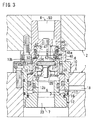
図3に示すように、上記の第1給排路7の圧油(圧力流体)の圧力が上方へ作用する弁ケース15の受圧面積Aは、弁ケース15と第2弁部材45とが当接されることにより封止される部分の内側の受圧面積Bよりも大きく設定される。このため、第1給排路7に供給された圧油(圧力流体)が弁ケースを上方へ押圧する。
また、前記第2給排路8の圧力流体の圧力が下方へ作用する前記第2弁部材45の受圧面積Cは、上記の封止断面積Bよりも大きく設定される。このため、第2給排路8に供給された圧油(圧力流体)が第2弁部材45を下方へ押圧する。
上記の受圧面積Aは、上記の受圧面積Cよりも大きく設定されている。このため、第1給排路7の圧油が第1弁ケース15を上方へ押す力が、第2給排路8の圧油が第2弁部材45を下方へ押す力よりも大きくなる。その結果、弁ケース15が第2弁部材45の封止部材52に向けて確実に押圧される。As shown in FIG. 3, the pressure receiving area A of the
Further, the pressure receiving area C of the
The pressure receiving area A is set larger than the pressure receiving area C. For this reason, the force by which the pressure oil in the first supply /
上記のカップリング装置は、図1から図3に示すように、次のように作動する。
図1の分離状態では、第1継手5のロック室16から圧油が排出されると共に、リリースバネ20が弁ケース15を下方へ移動させている。また、第1閉弁バネ28が第1弁部材25を上方に移動させている。
上記の第2継手6では、第2閉弁バネ47が第2弁部材45を下方に移動させている。The coupling device operates as follows, as shown in FIGS.
In the separated state of FIG. 1, the pressure oil is discharged from the
In the second joint 6 described above, the second
前記のワークパレット2を図1の分離状態から図3の連結状態に切換えるときには、まず、図1に示すように、第2継手6を第1継手5の上方へ移動する。次いで、第2継手6を下方へ移動させていくと、弁ケース15の突出部分15cの上面に第2弁部材45の封止部材52が当接する。さらに、図2に示すように、第1継手5の支持面10bに第2継手6の被支持面40aが当接する。
次いで、ロック室16に圧油を供給すると、弁ケース15がリリースバネ20に抗して上方へ移動されていき、その弁ケース15が第2弁部材45を第2閉弁バネ47に抗して上方へ移動させていく。次いで、弁ケース15の上端部が、第2継手6の収容孔53に挿入されていき、第2弁部材45の第2弁面46が弁座部材42の第2弁座43から離間されて開弁される。これと同時に、第1弁部材25の大径部分25bの上面が弁座部材42の下面に当接されることにより、第1弁部材25の第1弁面27が弁ケース15の第1弁座21から離間されて開弁される。このため、第1継手5の第1給排路7と第2継手6の第2給排路8とが連通される。
最後に、図3に示すように、弁ケース15が収容孔53の底壁に受け止められ、第1継手5と第2継手6とが連結される。When the
Next, when pressure oil is supplied to the
Finally, as shown in FIG. 3, the
上記のカップリング装置を図3の連結状態から図1の分離状態へ切換えるときには、まず、ロック室16から圧油を排出すると、リリースバネ20が弁ケース15を下方へ移動させる。すると、第2閉弁バネ47が第2弁部材45を下方へ移動させると共に、第1閉弁バネ28が第1弁部材25を閉弁方向へ移動させる。これにより、第1弁部材25の第1弁面27が第1ケーシング10の第1弁座21に当接して閉弁されると共に、第2弁部材45の第2弁面46が弁座部材42の第2弁座43に当接して閉弁する。
その後、図2の状態からワークパレット2を上方へ搬出すると、図1に示すように、第2継手6が第1継手5から分離される。When the coupling device is switched from the connected state of FIG. 3 to the separated state of FIG. 1, first, when the pressure oil is discharged from the
Thereafter, when the
上記の第1実施形態は次の長所を奏する。
上記の第1継手5と第2継手6とが離間された状態で、何らかの原因、例えば、駆動手段Dが誤作動したり誤操作されたりすることにより、弁ケース15がリリースバネ20に抗して上方へ移動されることがある。このような場合でも、第1閉弁バネ28によって第1弁部材25の第1弁面27が弁ケース15の第1弁座21に当接された閉弁状態が維持されている。このため、第1給排路7に供給された圧油が、第1弁面27と第1弁座21との間から外部へ流出するのを防止できる。The first embodiment described above has the following advantages.
When the first joint 5 and the second joint 6 are separated from each other, the
図4Aおよび図4Bは、本発明の第2実施形態を示している。この第2実施形態においては、上記の第1実施形態の構成部材と同じ部材(または類似する部材)には原則として同一の参照数字を付けて説明する。
この第2実施形態が上記の第1実施形態と異なる点は次の通りである。4A and 4B show a second embodiment of the present invention. In the second embodiment, the same members (or similar members) as the constituent members of the first embodiment will be described with the same reference numerals in principle.
The second embodiment is different from the first embodiment as follows.
第1継手5では、弁ケース15の小径部分15bに装着孔55が上方へ開口され、その装着孔55の底壁から弁座部材56が上方へ突設される。その弁座部材56の外周部に突出部分56aが上方に向かうにつれて広がるように形成され、その突出部分56aのテーパ外周部に第1弁座21が形成される。また、装着孔55に筒状の第1弁部材25が上下方向へ移動可能で保密状に挿入される。その突出部分15cの内周壁に第1弁面27が上方へ向かうにつれて軸心から遠ざかるように形成される。前記の装着孔55の底壁と第1弁部材25との間に第1閉弁バネ28が装着され、その第1閉弁バネ28が第1弁部材25を弁座部材56に向けて付勢している。このため、その第1弁面27が第1弁座21に当接されて閉弁されている。 In the first joint 5, a mounting
上記の第1給排路7は、第1弁座21と第1弁面27との間に形成された開弁隙間と、装着孔55と、その装着孔55の底壁に形成された連通孔57と、内筒12の内周孔に形成された第1給排口30とによって構成される。 The first supply /
上記の第1弁部材25の上端部に溝60が形成され、その溝60に封止部材61が装着される。上記の弁ケース15が上方へロック駆動されたときに、駆動手段Dが弁ケース15と第1閉弁バネ28とを介して第1弁部材25の封止部材61を第2ケーシング40の下端面に当接させる。 A
第2継手6では、第2ケーシング40の内周孔の下端部に突出部分40bが半径方向の内方へ突設され、その突出部分40の内周壁に第2弁座43が下方へ向かうにつれて狭まるように形成される。第2ケーシング40の内周孔の途中高さ部にリング状の案内部材65が止め輪66によって固定される。その案内部材65の内周孔に第2弁部材45の小径部分45aが上下方向に移動可能に挿入される。その小径部分45aに大径部分45bが下方に突設され、その大径部分45bの外周部が下方へ向かうにつれて狭まるように形成される。その大径部分45bの外周部に第2弁面46が形成される。案内部材65と第2弁部材45の大径部分45bとの間に第2閉弁バネ47が装着され、その第2閉弁バネ47が第2弁部材45を第2ケーシング40の突出部分40bに向けて付勢している。このため、その第2弁面46が第2弁座43に当接されて閉弁されている。 In the
上記の第2給排路8は、第2弁座43と第2弁面46との間に形成された開弁隙間と、第2ケーシング40の内周孔と、案内部材65に上下方向に形成された連通孔49と、第2ケーシング40の上部に形成された第2給排口50とによって構成される。 The second supply /
上記のカップリング装置は、図4Aから図4Bに示すように、次のように作動する。
図4Aの分離状態では、第1継手5のロック室16から圧油が排出されると共に、リリースバネ20が弁ケース15を下方へ移動させている。また、第1閉弁バネ28が第1弁部材25を弁座部材56の突出部分56aに向けて付勢している。これにより、第1弁面27が第1弁座21に当接されて閉弁されている。
また、第2継手6の第2閉弁バネ47が第2弁部材45を第2ケーシング40の突出部分40bに向けて移動させている。これにより、第2弁面46が第2弁座43に当接されて閉弁されている。The coupling device operates as follows, as shown in FIGS. 4A to 4B.
4A, the pressure oil is discharged from the
The second
上記のカップリング装置を図4Aの分離状態から図4Bの連結状態へ切換えるときには、まず、前記のワークパレット2をクランプパレット1の上方へ移動させ、次いで、図4Aの離間状態からワークパレット2を下降させていく。すると、第1弁部材25の封止部材61が第2ケーシング40の下端面に当接する。さらに、第1継手5の支持面10bに第2継手6の被支持面40aが当接する。
次いで、ロック室16に圧油を供給すると、そのロック室16の圧油が弁ケース15をリリースバネ20に抗して上方へ移動させていく。すると、第1弁部材25が第2ケーシング40に受け止められ、弁座部材56が第1閉弁バネ28に抗して上方へ移動される。これにより、第1弁面27が第1弁座21から離間されて開弁される。また、弁座部材56の上面が第2弁部材45の下面に当接されることにより、その第2弁部材45を上方へ移動させる。これにより、第2弁面46が第2弁座43から離間されて開弁される。その結果、第1継手5の第1給排口30と第2継手6の第2給排口50とが連通される。
最後に、図4Bに示すように、弁ケース15の大径部分15aの上面が、外筒11の内周壁に形成された段差部11aに上方から受け止められる。これにより、第1継手5と第2継手6とが連結される。When the coupling device is switched from the separated state shown in FIG. 4A to the connected state shown in FIG. 4B, the
Next, when pressure oil is supplied to the
Finally, as shown in FIG. 4B, the upper surface of the large-
上記のカップリング装置を図4Bの連結状態から図4Aの分離状態へ切換えるときには、まず、ロック室16から圧油を排出すると、リリースバネ20が弁ケース15を下方へ移動させる。すると、第2閉弁バネ47が第2弁部材45を下方へ移動させると共に、第1閉弁バネ28が第1弁部材25を上方へ移動させる。これにより、第1弁面27が第1弁座21に当接して閉弁されると共に、第2弁面46が第2弁座43に当接して閉弁される。
その後、ワークパレット2を上方へ搬出すると、図1に示すように、第1継手5と第2継手6とが分離される。When the coupling device is switched from the connected state of FIG. 4B to the separated state of FIG. 4A, first, when the pressure oil is discharged from the
Thereafter, when the
上記の第2実施形態は次の長所を奏する。
上記の第1継手5と第2継手6とが離間された状態で、何らかの原因、例えば、駆動手段Dが誤作動したり誤動作されたりすることにより、弁ケース15がリリースバネ20に抗して上方へ移動されることがある。このような場合でも、第1閉弁バネ28によって第1弁部材25の第1弁面27が弁ケース15の第1弁座21に当接されて閉弁状態が維持されている。このため、第1給排路7に供給された圧油が、第1弁面27と第1弁座21との間から外部へ流出するのを防止できる。The second embodiment has the following advantages.
When the first joint 5 and the second joint 6 are separated from each other, for some reason, for example, the drive means D malfunctions or malfunctions, the
上記の各実施形態は次のように変更可能である。
上記の第1継手5と第2継手6との配置方向が上下方向に限られず、左右方向であってもよく、また、上下方向に対して傾斜した方向であってもよい。
上記の給排路7,8に給排される流体は、例示した圧油に代えて、他の液体または圧縮空気等の気体であってもよい。
上記の駆動手段Dは、第1ケーシング10内にリリースバネ20を装着するのに代えてロック室16にロックバネを装着してもよい。また、駆動手段Dは、例示した単動式のシリンダに代えて複動式のシリンダであってもよい。さらには、駆動手段Dを駆動させる圧力流体は、例示の油圧に代えて、他の液体または圧縮空気等の気体であってもよい。
上記の付勢手段は、例示した閉弁バネ28,47に代えて、ゴムやガススプリングであってもよい。
上記の支持面10bが、第1ケーシング10に形成されるのに代えて、クランプパレット1等の他の場所に設けられてもよい。また、上記の被支持面40aが、第2ケーシング40に形成されるのに代えて、ワークパレット2等の他の場所に設けられてもよい。
その他に、当業者が想定できる範囲で種々の変更を行えることは勿論である。Each of the above embodiments can be modified as follows.
The arrangement direction of the first joint 5 and the
The fluid supplied to and discharged from the supply and
The driving means D may mount a lock spring in the
The biasing means may be a rubber or a gas spring instead of the illustrated valve closing springs 28 and 47.
Instead of being formed on the
In addition, it is needless to say that various modifications can be made within a range that can be assumed by those skilled in the art.
5:第1継手,6:第2継手,7:第1給排路,8:第2給排路,10:第1ケーシング,15:弁ケース,20:リリースバネ,21第1弁座,25:第1弁部材,27:第1弁面,28:第1付勢手段(第1閉弁バネ),40:第2ケーシング,42:弁座部材,43:第2弁座,45:第2弁部材,46:第2弁面,47:第2付勢手段(第2閉弁バネ),56:弁座部材,D:駆動手段.5: first joint, 6: second joint, 7: first supply / discharge path, 8: second supply / discharge path, 10: first casing, 15: valve case, 20: release spring, 21 first valve seat, 25: first valve member, 27: first valve surface, 28: first urging means (first valve closing spring), 40: second casing, 42: valve seat member, 43: second valve seat, 45: Second valve member, 46: second valve surface, 47: second urging means (second valve closing spring), 56: valve seat member, D: driving means.
Claims (3)
前記第1継手(5)は、第1ケーシング(10)内に軸心方向に移動可能で保密状に挿入された筒状の弁ケース(15)と、
前記第1ケーシング(10)内に設けられた駆動手段(D)であって、前記弁ケース(15)を先端側へ進出および基端側へ後退させる駆動手段(D)と、
前記弁ケース(15)の先端部分に設けられた第1弁座(21)と、
前記弁ケース(15)内に軸心方向に移動可能に挿入された第1弁部材(25)であって、前記第1弁座(21)に前記基端側から当接される第1弁面(27)を有する第1弁部材(25)と、
前記第1弁面(27)を前記第1弁座(21)に向けて付勢する第1付勢手段(28)と、を備え、
前記第2継手(6)は、第2ケーシング(40)に設けられた弁座部材(42)であって、第2弁座(43)を有する弁座部材(42)と、
前記第2ケーシング(40)内に軸心方向に移動可能で保密状に挿入された筒状の第2弁部材(45)であって、前記第2弁座(43)に前記先端側から当接される第2弁面(46)を有する第2弁部材(45)と、
前記第2弁面(46)を前記第2弁座(43)に向けて付勢する第2付勢手段(47)と、を備え、
前記第1ケーシング(10)は、
外筒(11)と、
前記外筒(11)の内周孔の基端部に固定される内筒(12)と、を有し、
前記内筒(12)は、前記外筒(11)に保密状に固定される大径部分(12a)と、その大径部分(12a)の先端側に設けられた小径部分(12b)と、を有し、
前記内筒(12)の前記小径部分(12b)と前記外筒(11)の内周孔との間に隙間が形成され、
前記隙間に前記弁ケース(15)の大径部分(15a)が保密状で前記軸心方向に移動可能に挿入され、
前記駆動手段(D)は、
前記外筒(11)の内周孔と前記内筒(12)の外周部と前記弁ケース(15)の前記大径部分(15a)とによって区画形成されたロック室(16)であって、圧力流体が供給および排出されるロック室(16)と、
前記第1ケーシング(10)内、且つ前記弁ケース(15)の前記大径部分(12a)の先端側に突設された小径部分(15b)の外周側に装着されたリリースバネ(20)であって、前記弁ケース(15)を前記基端側に向けて付勢するリリースバネ(20)と、を有し、
前記弁ケース(15)の内周孔、および前記内筒(12)の内周孔によって前記第1給排路(7)の一部が構成される、
ことを特徴とするカップリング装置。 A first joint (5) and a second joint (6) detachably connected to the first joint (5) from the tip side are provided, and a first supply provided in the first joint (5) In the coupling device for detachably connecting the discharge passage (7) and the second supply / discharge passage (8) provided in the second joint (6),
The first joint (5) is a cylindrical valve case (15) which is movable in the axial direction in the first casing (10) and is inserted in a tightly sealed manner;
Drive means (D) provided in the first casing (10), wherein the valve case (15) is advanced to the distal end side and retracted to the proximal end side;
A first valve seat (21) provided at the tip of the valve case (15);
A first valve member (25), which is inserted into the valve case (15) so as to be movable in the axial direction, and is in contact with the first valve seat (21) from the base end side. A first valve member (25) having a surface (27);
First urging means (28) for urging the first valve surface (27) toward the first valve seat (21),
The second joint (6) is a valve seat member (42) provided in the second casing (40), the valve seat member (42) having the second valve seat (43),
A cylindrical second valve member (45) that is axially movable in the second casing (40) and is inserted in a close-packed manner, and contacts the second valve seat (43) from the tip side. A second valve member (45) having a second valve face (46) in contact therewith;
Second urging means (47) for urging the second valve surface (46) toward the second valve seat (43) ;
The first casing (10)
An outer cylinder (11),
An inner cylinder (12) fixed to the proximal end portion of the inner peripheral hole of the outer cylinder (11),
The inner cylinder (12) includes a large-diameter portion (12a) fixed in a close-tight manner to the outer cylinder (11), and a small-diameter portion (12b) provided on the distal end side of the large-diameter portion (12a), Have
A gap is formed between the small diameter portion (12b) of the inner cylinder (12) and the inner peripheral hole of the outer cylinder (11),
The large-diameter portion (15a) of the valve case (15) is inserted into the gap so as to be concentrically movable in the axial direction,
The driving means (D)
A lock chamber (16) defined by an inner peripheral hole of the outer cylinder (11), an outer peripheral part of the inner cylinder (12), and the large-diameter portion (15a) of the valve case (15); A lock chamber (16) into which pressure fluid is supplied and discharged ;
A release spring (20) mounted on the outer peripheral side of the small diameter portion (15b) projecting from the distal end side of the large diameter portion (12a) of the valve casing (15) in the first casing (10). A release spring (20) for biasing the valve case (15) toward the base end side,
A part of the first supply / discharge passage (7) is constituted by the inner peripheral hole of the valve case (15) and the inner peripheral hole of the inner cylinder (12).
A coupling device characterized by that.
前記第1給排路(7)の圧力流体の圧力が先端方向へ作用する前記弁ケース(15)の受圧面積(A)は、前記弁ケース(15)と前記第2弁部材(45)とが当接されることにより封止される部分の内側の受圧面積(B)よりも大きく設定され、
前記第2給排路(8)の圧力流体の圧力が基端方向へ作用する前記第2弁部材(45)の受圧面積(C)は、上記の封止断面積(B)よりも大きく設定され、
上記の受圧面積(A)は、上記の受圧面積(C)よりも大きく設定されている、ことを特徴とするカップリング装置。 The coupling device of claim 1 .
The pressure receiving area (A) of the valve case (15) on which the pressure of the pressure fluid in the first supply / discharge path (7) acts in the distal direction is the valve case (15) and the second valve member (45). Is set to be larger than the pressure receiving area (B) inside the portion sealed by abutting,
The pressure receiving area (C) of the second valve member (45) on which the pressure of the pressurized fluid in the second supply / discharge passage (8) acts in the proximal direction is set larger than the sealing cross-sectional area (B). And
The coupling device, wherein the pressure receiving area (A) is set larger than the pressure receiving area (C).
前記第1継手(5)は、第1ケーシング(10)内に軸心方向に移動可能で保密状に挿入された筒状の弁ケース(15)と、
前記第1ケーシング(10)内に設けられた駆動手段(D)であって、前記弁ケース(15)を先端側へ進出および基端側へ後退させる駆動手段(D)と、
前記弁ケース(15)に設けられた弁座部材(56)であって、当該弁座部材(56)の先端部分に設けられた第1弁座(21)を有する弁座部材(56)と、
前記弁ケース(15)内に軸心方向に移動可能に保密状に挿入された第1弁部材(25)であって、前記第1弁座(21)に基端側から当接される第1弁面(27)を有する第1弁部材(25)と、
前記第1弁面(27)を前記第1弁座(21)に向けて付勢する第1付勢手段(28)
と、を備え、
前記第2継手(6)は、第2ケーシング(40)の基端部分に設けられた第2弁座(43)と、
前記第2ケーシング(40)内に軸心方向に移動可能で保密状に挿入された筒状の第2弁部材(45)であって、前記第2弁座(43)に先端側から当接される第2弁面(46)を有する第2弁部材(45)と、
前記第2弁面(46)を第2弁座(43)に向けて付勢する第2付勢手段(47)と、を備え、
前記第1ケーシング(10)は、
外筒(11)と、
前記外筒(11)の内周孔の基端部に固定される内筒(12)と、を有し、
前記内筒(12)は、前記外筒(11)に保密状に固定される大径部分(12a)と、その大径部分(12a)の先端側に設けられた小径部分(12b)と、を有し、
前記内筒(12)の前記小径部分(12b)と前記外筒(11)の内周孔との間に隙間が形成され、
前記隙間に前記弁ケース(15)の大径部分(15a)が保密状で前記軸心方向に移動可能に挿入され、
前記駆動手段(D)は、
前記外筒(11)の内周孔と前記内筒(12)の外周部と前記弁ケース(15)の前記大径部分(15a)とによって区画形成されたロック室(16)であって、圧力流体が供給および排出されるロック室(16)と、
前記第1ケーシング(10)内、且つ前記弁ケース(15)の前記大径部分(12a)の先端側に突設された小径部分(15b)の外周側に装着されたリリースバネ(20)であって、前記弁ケース(15)を前記基端側に向けて付勢するリリースバネ(20)と、を有し、
前記弁ケース(15)の内周孔、および前記内筒(12)の内周孔によって前記第1給排路(7)の一部が構成される、
ことを特徴とするカップリング装置。 A first joint (5) and a second joint (6) detachably connected to the first joint (5) from the tip side are provided, and a first supply provided in the first joint (5) In the coupling device for detachably connecting the discharge passage (7) and the second supply / discharge passage (8) provided in the second joint (6),
The first joint (5) is a cylindrical valve case (15) which is movable in the axial direction in the first casing (10) and is inserted in a tightly sealed manner;
Drive means (D) provided in the first casing (10), wherein the valve case (15) is advanced to the distal end side and retracted to the proximal end side;
A valve seat member (56) provided in the valve case (15), the valve seat member (56) having a first valve seat (21) provided at a tip portion of the valve seat member (56); ,
A first valve member (25) inserted in the valve case (15) so as to be movable in the axial direction so as to move in an axial direction, and is in contact with the first valve seat (21) from the base end side. A first valve member (25) having one valve face (27);
First urging means (28) for urging the first valve surface (27) toward the first valve seat (21)
And comprising
The second joint (6) includes a second valve seat (43) provided at a proximal end portion of the second casing (40),
A cylindrical second valve member (45) that is movable in the axial direction in the second casing (40) and is inserted in a close-packed manner, and comes into contact with the second valve seat (43) from the front end side. A second valve member (45) having a second valve face (46) to be
Second urging means (47) for urging the second valve surface (46) toward the second valve seat (43) ,
The first casing (10)
An outer cylinder (11),
An inner cylinder (12) fixed to the proximal end portion of the inner peripheral hole of the outer cylinder (11),
The inner cylinder (12) includes a large-diameter portion (12a) fixed in a close-tight manner to the outer cylinder (11), and a small-diameter portion (12b) provided on the distal end side of the large-diameter portion (12a), Have
A gap is formed between the small diameter portion (12b) of the inner cylinder (12) and the inner peripheral hole of the outer cylinder (11),
The large-diameter portion (15a) of the valve case (15) is inserted into the gap so as to be concentrically movable in the axial direction,
The driving means (D)
A lock chamber (16) defined by an inner peripheral hole of the outer cylinder (11), an outer peripheral part of the inner cylinder (12), and the large-diameter portion (15a) of the valve case (15); A lock chamber (16) into which pressure fluid is supplied and discharged ;
A release spring (20) mounted on the outer peripheral side of the small diameter portion (15b) projecting from the distal end side of the large diameter portion (12a) of the valve casing (15) in the first casing (10). A release spring (20) for biasing the valve case (15) toward the base end side,
A part of the first supply / discharge passage (7) is constituted by the inner peripheral hole of the valve case (15) and the inner peripheral hole of the inner cylinder (12).
A coupling device characterized by that.
Priority Applications (1)
| Application Number | Priority Date | Filing Date | Title |
|---|---|---|---|
| JP2015154566A JP6567916B2 (en) | 2015-07-16 | 2015-07-16 | Coupling device |
Applications Claiming Priority (1)
| Application Number | Priority Date | Filing Date | Title |
|---|---|---|---|
| JP2015154566A JP6567916B2 (en) | 2015-07-16 | 2015-07-16 | Coupling device |
Publications (2)
| Publication Number | Publication Date |
|---|---|
| JP2017026131A JP2017026131A (en) | 2017-02-02 |
| JP6567916B2 true JP6567916B2 (en) | 2019-08-28 |
Family
ID=57945726
Family Applications (1)
| Application Number | Title | Priority Date | Filing Date |
|---|---|---|---|
| JP2015154566A Active JP6567916B2 (en) | 2015-07-16 | 2015-07-16 | Coupling device |
Country Status (1)
| Country | Link |
|---|---|
| JP (1) | JP6567916B2 (en) |
Families Citing this family (2)
| Publication number | Priority date | Publication date | Assignee | Title |
|---|---|---|---|---|
| JP7197129B2 (en) * | 2018-10-29 | 2022-12-27 | 株式会社コスメック | Manual connection device |
| DE102020127608A1 (en) | 2020-10-20 | 2022-04-21 | Wto Vermögensverwaltung Gmbh | Coupling device for releasably establishing a hydraulic connection |
Family Cites Families (4)
| Publication number | Priority date | Publication date | Assignee | Title |
|---|---|---|---|---|
| CN101678585B (en) * | 2007-05-30 | 2012-12-05 | 帕斯卡工程株式会社 | Coupling device |
| JP5051905B2 (en) * | 2008-02-18 | 2012-10-17 | パスカルエンジニアリング株式会社 | Fluid passage connection device |
| JP3173825U (en) * | 2011-12-09 | 2012-02-23 | パスカルエンジニアリング株式会社 | Coupling device |
| JP3179484U (en) * | 2012-08-24 | 2012-11-01 | パスカルエンジニアリング株式会社 | Coupling device |
-
2015
- 2015-07-16 JP JP2015154566A patent/JP6567916B2/en active Active
Also Published As
| Publication number | Publication date |
|---|---|
| JP2017026131A (en) | 2017-02-02 |
Similar Documents
| Publication | Publication Date | Title |
|---|---|---|
| JP5827602B2 (en) | Clamping device | |
| JP6641358B2 (en) | Cylinder device | |
| JP4864164B2 (en) | Clamping system with fluid coupler | |
| KR101751509B1 (en) | Clamp device | |
| JP6552310B2 (en) | Cylinder device | |
| JP6567916B2 (en) | Coupling device | |
| JP6211851B2 (en) | Clamping device | |
| JP6208480B2 (en) | Cylinder device with booster mechanism | |
| JP6298294B2 (en) | Cylinder device | |
| JP6886653B2 (en) | Clamp device with temporary lock function | |
| JP6218308B2 (en) | Work palette | |
| JPWO2019059136A1 (en) | Cylinder device with sequence valve | |
| JP2011143531A (en) | Clamp device | |
| JP2012091308A (en) | Work support | |
| JP2017154212A (en) | Positioning device with operation detection function | |
| JP6617021B2 (en) | Clamping device with abnormal state detection mechanism | |
| JP3173825U (en) | Coupling device | |
| JP6971454B2 (en) | Cylinder device with detection valve | |
| JP2015003346A (en) | Clamp device | |
| JP4579832B2 (en) | Rapid fitting | |
| JP6670528B2 (en) | Positioning device with breakage detection function | |
| JP2014108470A (en) | Clamp device | |
| JP6683472B2 (en) | Clamp device | |
| KR102571846B1 (en) | Pneumatic cylinder device with retaining valve | |
| JP2012143868A (en) | Clamp device |
Legal Events
| Date | Code | Title | Description |
|---|---|---|---|
| A621 | Written request for application examination |
Free format text: JAPANESE INTERMEDIATE CODE: A621 Effective date: 20180404 |
|
| A977 | Report on retrieval |
Free format text: JAPANESE INTERMEDIATE CODE: A971007 Effective date: 20190121 |
|
| A131 | Notification of reasons for refusal |
Free format text: JAPANESE INTERMEDIATE CODE: A131 Effective date: 20190125 |
|
| A521 | Request for written amendment filed |
Free format text: JAPANESE INTERMEDIATE CODE: A523 Effective date: 20190315 |
|
| RD02 | Notification of acceptance of power of attorney |
Free format text: JAPANESE INTERMEDIATE CODE: A7422 Effective date: 20190315 |
|
| TRDD | Decision of grant or rejection written | ||
| A01 | Written decision to grant a patent or to grant a registration (utility model) |
Free format text: JAPANESE INTERMEDIATE CODE: A01 Effective date: 20190730 |
|
| A61 | First payment of annual fees (during grant procedure) |
Free format text: JAPANESE INTERMEDIATE CODE: A61 Effective date: 20190801 |
|
| R150 | Certificate of patent or registration of utility model |
Ref document number: 6567916 Country of ref document: JP Free format text: JAPANESE INTERMEDIATE CODE: R150 |
|
| R250 | Receipt of annual fees |
Free format text: JAPANESE INTERMEDIATE CODE: R250 |
|
| R250 | Receipt of annual fees |
Free format text: JAPANESE INTERMEDIATE CODE: R250 |
|
| R250 | Receipt of annual fees |
Free format text: JAPANESE INTERMEDIATE CODE: R250 |