JP6567687B2 - Automatic syringe drive mechanism - Google Patents
Automatic syringe drive mechanism Download PDFInfo
- Publication number
- JP6567687B2 JP6567687B2 JP2017555544A JP2017555544A JP6567687B2 JP 6567687 B2 JP6567687 B2 JP 6567687B2 JP 2017555544 A JP2017555544 A JP 2017555544A JP 2017555544 A JP2017555544 A JP 2017555544A JP 6567687 B2 JP6567687 B2 JP 6567687B2
- Authority
- JP
- Japan
- Prior art keywords
- rotor
- actuator
- drive mechanism
- drug delivery
- plunger rod
- Prior art date
- Legal status (The legal status is an assumption and is not a legal conclusion. Google has not performed a legal analysis and makes no representation as to the accuracy of the status listed.)
- Active
Links
- 230000007246 mechanism Effects 0.000 title claims description 28
- 238000012377 drug delivery Methods 0.000 claims description 62
- 239000012190 activator Substances 0.000 claims description 24
- 239000003814 drug Substances 0.000 description 23
- 229940079593 drug Drugs 0.000 description 20
- 230000001681 protective effect Effects 0.000 description 5
- 239000000243 solution Substances 0.000 description 5
- 238000002347 injection Methods 0.000 description 4
- 239000007924 injection Substances 0.000 description 4
- 230000035515 penetration Effects 0.000 description 4
- 239000006199 nebulizer Substances 0.000 description 2
- 230000002093 peripheral effect Effects 0.000 description 2
- 230000004913 activation Effects 0.000 description 1
- 239000006071 cream Substances 0.000 description 1
- 230000001419 dependent effect Effects 0.000 description 1
- 239000000843 powder Substances 0.000 description 1
- 230000037452 priming Effects 0.000 description 1
- 230000001960 triggered effect Effects 0.000 description 1
Images


Classifications
-
- A—HUMAN NECESSITIES
- A61—MEDICAL OR VETERINARY SCIENCE; HYGIENE
- A61M—DEVICES FOR INTRODUCING MEDIA INTO, OR ONTO, THE BODY; DEVICES FOR TRANSDUCING BODY MEDIA OR FOR TAKING MEDIA FROM THE BODY; DEVICES FOR PRODUCING OR ENDING SLEEP OR STUPOR
- A61M5/00—Devices for bringing media into the body in a subcutaneous, intra-vascular or intramuscular way; Accessories therefor, e.g. filling or cleaning devices, arm-rests
- A61M5/178—Syringes
- A61M5/20—Automatic syringes, e.g. with automatically actuated piston rod, with automatic needle injection, filling automatically
- A61M5/2033—Spring-loaded one-shot injectors with or without automatic needle insertion
-
- A—HUMAN NECESSITIES
- A61—MEDICAL OR VETERINARY SCIENCE; HYGIENE
- A61M—DEVICES FOR INTRODUCING MEDIA INTO, OR ONTO, THE BODY; DEVICES FOR TRANSDUCING BODY MEDIA OR FOR TAKING MEDIA FROM THE BODY; DEVICES FOR PRODUCING OR ENDING SLEEP OR STUPOR
- A61M5/00—Devices for bringing media into the body in a subcutaneous, intra-vascular or intramuscular way; Accessories therefor, e.g. filling or cleaning devices, arm-rests
- A61M5/178—Syringes
- A61M5/31—Details
- A61M5/3148—Means for causing or aiding aspiration or plunger retraction
-
- A—HUMAN NECESSITIES
- A61—MEDICAL OR VETERINARY SCIENCE; HYGIENE
- A61M—DEVICES FOR INTRODUCING MEDIA INTO, OR ONTO, THE BODY; DEVICES FOR TRANSDUCING BODY MEDIA OR FOR TAKING MEDIA FROM THE BODY; DEVICES FOR PRODUCING OR ENDING SLEEP OR STUPOR
- A61M5/00—Devices for bringing media into the body in a subcutaneous, intra-vascular or intramuscular way; Accessories therefor, e.g. filling or cleaning devices, arm-rests
- A61M5/178—Syringes
- A61M5/31—Details
- A61M5/315—Pistons; Piston-rods; Guiding, blocking or restricting the movement of the rod or piston; Appliances on the rod for facilitating dosing ; Dosing mechanisms
- A61M5/31511—Piston or piston-rod constructions, e.g. connection of piston with piston-rod
-
- A—HUMAN NECESSITIES
- A61—MEDICAL OR VETERINARY SCIENCE; HYGIENE
- A61M—DEVICES FOR INTRODUCING MEDIA INTO, OR ONTO, THE BODY; DEVICES FOR TRANSDUCING BODY MEDIA OR FOR TAKING MEDIA FROM THE BODY; DEVICES FOR PRODUCING OR ENDING SLEEP OR STUPOR
- A61M5/00—Devices for bringing media into the body in a subcutaneous, intra-vascular or intramuscular way; Accessories therefor, e.g. filling or cleaning devices, arm-rests
- A61M5/178—Syringes
- A61M5/31—Details
- A61M5/315—Pistons; Piston-rods; Guiding, blocking or restricting the movement of the rod or piston; Appliances on the rod for facilitating dosing ; Dosing mechanisms
- A61M5/31565—Administration mechanisms, i.e. constructional features, modes of administering a dose
- A61M5/31576—Constructional features or modes of drive mechanisms for piston rods
-
- A—HUMAN NECESSITIES
- A61—MEDICAL OR VETERINARY SCIENCE; HYGIENE
- A61M—DEVICES FOR INTRODUCING MEDIA INTO, OR ONTO, THE BODY; DEVICES FOR TRANSDUCING BODY MEDIA OR FOR TAKING MEDIA FROM THE BODY; DEVICES FOR PRODUCING OR ENDING SLEEP OR STUPOR
- A61M5/00—Devices for bringing media into the body in a subcutaneous, intra-vascular or intramuscular way; Accessories therefor, e.g. filling or cleaning devices, arm-rests
- A61M5/178—Syringes
- A61M5/20—Automatic syringes, e.g. with automatically actuated piston rod, with automatic needle injection, filling automatically
- A61M2005/2006—Having specific accessories
- A61M2005/2013—Having specific accessories triggering of discharging means by contact of injector with patient body
-
- A—HUMAN NECESSITIES
- A61—MEDICAL OR VETERINARY SCIENCE; HYGIENE
- A61M—DEVICES FOR INTRODUCING MEDIA INTO, OR ONTO, THE BODY; DEVICES FOR TRANSDUCING BODY MEDIA OR FOR TAKING MEDIA FROM THE BODY; DEVICES FOR PRODUCING OR ENDING SLEEP OR STUPOR
- A61M5/00—Devices for bringing media into the body in a subcutaneous, intra-vascular or intramuscular way; Accessories therefor, e.g. filling or cleaning devices, arm-rests
- A61M5/178—Syringes
- A61M5/31—Details
- A61M5/315—Pistons; Piston-rods; Guiding, blocking or restricting the movement of the rod or piston; Appliances on the rod for facilitating dosing ; Dosing mechanisms
- A61M5/31565—Administration mechanisms, i.e. constructional features, modes of administering a dose
- A61M5/31576—Constructional features or modes of drive mechanisms for piston rods
- A61M2005/31588—Constructional features or modes of drive mechanisms for piston rods electrically driven
-
- A—HUMAN NECESSITIES
- A61—MEDICAL OR VETERINARY SCIENCE; HYGIENE
- A61M—DEVICES FOR INTRODUCING MEDIA INTO, OR ONTO, THE BODY; DEVICES FOR TRANSDUCING BODY MEDIA OR FOR TAKING MEDIA FROM THE BODY; DEVICES FOR PRODUCING OR ENDING SLEEP OR STUPOR
- A61M5/00—Devices for bringing media into the body in a subcutaneous, intra-vascular or intramuscular way; Accessories therefor, e.g. filling or cleaning devices, arm-rests
- A61M5/178—Syringes
- A61M5/31—Details
- A61M5/315—Pistons; Piston-rods; Guiding, blocking or restricting the movement of the rod or piston; Appliances on the rod for facilitating dosing ; Dosing mechanisms
- A61M5/31565—Administration mechanisms, i.e. constructional features, modes of administering a dose
-
- A—HUMAN NECESSITIES
- A61—MEDICAL OR VETERINARY SCIENCE; HYGIENE
- A61M—DEVICES FOR INTRODUCING MEDIA INTO, OR ONTO, THE BODY; DEVICES FOR TRANSDUCING BODY MEDIA OR FOR TAKING MEDIA FROM THE BODY; DEVICES FOR PRODUCING OR ENDING SLEEP OR STUPOR
- A61M5/00—Devices for bringing media into the body in a subcutaneous, intra-vascular or intramuscular way; Accessories therefor, e.g. filling or cleaning devices, arm-rests
- A61M5/178—Syringes
- A61M5/31—Details
- A61M5/32—Needles; Details of needles pertaining to their connection with syringe or hub; Accessories for bringing the needle into, or holding the needle on, the body; Devices for protection of needles
- A61M5/3205—Apparatus for removing or disposing of used needles or syringes, e.g. containers; Means for protection against accidental injuries from used needles
- A61M5/321—Means for protection against accidental injuries by used needles
- A61M5/3243—Means for protection against accidental injuries by used needles being axially-extensible, e.g. protective sleeves coaxially slidable on the syringe barrel
- A61M5/326—Fully automatic sleeve extension, i.e. in which triggering of the sleeve does not require a deliberate action by the user
Landscapes
- Health & Medical Sciences (AREA)
- Vascular Medicine (AREA)
- Engineering & Computer Science (AREA)
- Anesthesiology (AREA)
- Biomedical Technology (AREA)
- Heart & Thoracic Surgery (AREA)
- Hematology (AREA)
- Life Sciences & Earth Sciences (AREA)
- Animal Behavior & Ethology (AREA)
- General Health & Medical Sciences (AREA)
- Public Health (AREA)
- Veterinary Medicine (AREA)
- Infusion, Injection, And Reservoir Apparatuses (AREA)
Description
技術分野
本発明は、薬剤送達装置の駆動機構に関し、特に、高度な自動機能を備えた薬剤送達装置に関する。
TECHNICAL FIELD The present invention relates to a driving mechanism of a drug delivery device, and more particularly, to a drug delivery device having a high degree of automatic function.
発明の背景
看護師や医師ではないユーザによって使用されたり取り扱われたりする、すなわち、患者自身によって取り扱われる用途に設計された薬剤送達装置が絶えず開発されている。本発明の出願人は、薬の混合、プライミング、貫入、注入・充填、および/または薬剤送達部材ガードの伸長を含む高度な自動機能を示す薬剤送達装置を大量に開発してきた。
BACKGROUND OF THE INVENTION Drug delivery devices are constantly being developed that are designed and used by users who are not nurses or doctors, ie, handled by the patient himself. Applicants of the present invention have developed a large number of drug delivery devices that exhibit highly automated functions including drug mixing, priming, penetration, injection / filling, and / or drug delivery member guard extension.
構成要素の数をできるだけ少なく抑えつつ、これらの多くの機能を創造するために、いわゆる回転子がこれまでよく使用されてきた。回転子は、薬剤送達装置の筐体内で回転可能な略筒状の構成要素であり、回転が引き起こされると、種々の機能を有効にするおよび/または実行する。 In order to create many of these functions while keeping the number of components as small as possible, so-called rotors have been used frequently. The rotor is a generally cylindrical component that is rotatable within the housing of the drug delivery device, and enables and / or performs various functions when rotation is triggered.
文献WO2011/123024は、このような回転子とともに構成された薬剤送達装置を開示している。回転子は、貫入シーケンスの間、薬剤送達部材ガードによって操作される。すると、回転子は、プランジャーロッドを伸長された状態で保持する保持部材に作用する。保持部材は、アームの形をしており、プランジャーロッドの凹部に嵌め込まれる内向きの凸部を有する。 Document WO2011 / 123024 discloses a drug delivery device constructed with such a rotor. The rotor is operated by the drug delivery member guard during the penetration sequence. Then, the rotor acts on a holding member that holds the plunger rod in an extended state. The holding member is in the form of an arm and has an inward convex portion that is fitted into the concave portion of the plunger rod.
回転子が特定の回転角度に回転して貫入シーケンスが完了すると、保持部材は回転子から解放され、これによってプランジャーロッドもまた自由になり、1回の投与量の薬剤を送達するために近位方向に動かされる。また、回転子は、注射後に薬剤送達装置が抜かれた後、薬剤送達部材ガードを伸長された位置にロックするなど、その他の特徴も有する。 When the rotor is rotated to a specific angle of rotation and the penetration sequence is complete, the retaining member is released from the rotor, which also frees the plunger rod and closes to deliver a single dose of medication. It is moved in the direction of position. The rotor also has other features, such as locking the drug delivery member guard in the extended position after the drug delivery device is removed after injection.
回転子を使用した解決法は、ほとんどの場合にとてもうまく作用し、より一般的な解決法と比べて構成要素の数が抑えられるが、回転子の回転運動が行われたとき、回転子と保持部材との間の摩擦によって保持部材が曲がってしまっていた。これによって、今度は保持部材が詰まってしまい、プランジャーロッドが解放されるべき時に解放されなかった。 The solution using the rotor works very well in most cases and reduces the number of components compared to the more general solution, but when the rotor is moved in rotation, the rotor and The holding member was bent by the friction with the holding member. This in turn caused the holding member to become clogged and not released when the plunger rod should be released.
発明の簡単な説明
本発明の目的は、従来の駆動機構の欠点を改善することである。この目的は、独立請求項の特徴を有する、薬剤送達装置の駆動機構によって達成される。好適な実施形態は、従属請求項に記載されている。
BRIEF DESCRIPTION OF THE INVENTION The object of the present invention is to remedy the drawbacks of conventional drive mechanisms. This object is achieved by a drive mechanism of a drug delivery device having the features of the independent claims. Preferred embodiments are described in the dependent claims.
本発明は、薬剤送達装置に使用される駆動機構に関する。好ましくは、駆動機構は、プランジャーロッドと、プランジャーロッドに対して操作可能に構成された駆動用ばねとを備え、プランジャーロッドは、薬剤容器内に配置されたストッパに対して作用するように構成されている。 The present invention relates to a drive mechanism used in a drug delivery device. Preferably, the drive mechanism includes a plunger rod and a drive spring configured to be operable with respect to the plunger rod, the plunger rod acting against a stopper disposed in the medicine container. It is configured.
さらに、駆動機構は、伸長状態の駆動用ばねを装填したプランジャーロッドを保持するためにプランジャーロッドと解放可能に係合された保持部材を備えるアクチュエータとともに構成されてもよい。また、回転子は、アクチュエータに操作可能に接続され、アクチュエータに対して可動であり、保持部材をプランジャーロッドと係合した状態に保持するために、保持部材と相互に作用し合うように構成される。 Further, the drive mechanism may be configured with an actuator that includes a holding member releasably engaged with the plunger rod to hold the plunger rod loaded with the extended drive spring. The rotor is operably connected to the actuator, is movable with respect to the actuator, and is configured to interact with the holding member to hold the holding member in a state engaged with the plunger rod. Is done.
さらに、アクティベータが回転子に操作可能に接続されてもよく、アクティベータは、回転子を回転させ、その後、保持部材がプランジャーロッドから解放されるように、回転子をアクチュエータに対して線形に転置するように構成される。この解決策では、回転子の最後の動きが線形な動きであるため、アクチュエータのロックを解除する前に回転子が回転することに関連したこれまでの問題を回避することができる。同時に、保持部材が詰まってしまうおそれが回避されるあるいは少なくとも大幅に低減される。 In addition, an activator may be operably connected to the rotor, the activator rotating the rotor linearly relative to the actuator so that the holding member is then released from the plunger rod. Configured to transpose. This solution avoids previous problems associated with rotating the rotor before unlocking the actuator, since the last movement of the rotor is a linear movement. At the same time, the risk of clogging the holding member is avoided or at least greatly reduced.
回転子の動きを制御するために、アクチュエータは、回転子が第1の位置から第2の位置まで回転されたときに回転子が載る突起とともに構成されてもよい。回転子の動きをさらに制御するために、回転子は、回転子の線形な動きを可能にするための第2の位置にあるとき、突起を差し込むことができる切欠きとともに構成されてもよい。したがって、第1の位置と第2の位置との間の回転運動において、回転子は突起によって案内されて、線形な動きは一切行わない。次に、第2の位置において、線形な動きが与えられて、突起が切欠きに差し込まれる。 In order to control the movement of the rotor, the actuator may be configured with a protrusion on which the rotor rests when the rotor is rotated from the first position to the second position. To further control the movement of the rotor, the rotor may be configured with a notch through which a protrusion can be inserted when in the second position to allow linear movement of the rotor. Therefore, in the rotational movement between the first position and the second position, the rotor is guided by the protrusion and does not perform any linear movement. Next, in a second position, a linear movement is applied and the protrusion is inserted into the notch.
回転運動をもたらすために、回転子は、長手方向に対して傾斜した第1案内隆起部を備えてもよく、アクティベータは、回転子を回転させるために、第1案内隆起部に対して作用する。したがって、傾斜面が、回転子を第1の位置から第2の位置まで回転させる手段を与える。 In order to provide a rotational movement, the rotor may comprise a first guide ridge inclined with respect to the longitudinal direction, and the activator acts on the first guide ridge to rotate the rotor. To do. Thus, the ramp provides a means for rotating the rotor from the first position to the second position.
回転子は、さらに、第1案内隆起部と相互に連結された第2案内隆起部を備えてもよく、第2案内隆起部は、長手方向を概ね横断しており、アクティベータは、回転子を動かすために、第2案内隆起部に対して作用する。 The rotor may further comprise a second guide ridge interconnected with the first guide ridge, wherein the second guide ridge is generally transverse to the longitudinal direction, and the activator includes the rotor. To move the second guide ridge.
回転子とアクチュエータとの間で正確で相対的な初期位置を得るために、回転子は、アクチュエータ上の第2方向付け要素と相互に作用し合うために操作可能に構成され、回転子にアクチュエータが組み合わされる際の方向付けの助けを提供するための第1方向付け要素を備えてもよい。 In order to obtain an accurate and relative initial position between the rotor and the actuator, the rotor is configured to be operable to interact with a second directing element on the actuator and There may be provided a first directing element to provide directing help when the are combined.
実現可能な一解決策によると、第1方向付け要素は、縦溝を備えてもよく、第2方向付け要素は、縦溝に嵌め込まれるように構成された凸部を備える。これによって、駆動機構の組立て時、回転子がアクチュエータに対して押される際に適切な方向付けが可能になり、アクチュエータに対する回転子の回転方向の位置合わせ不良のおそれを低減する。 According to one possible solution, the first directing element may comprise a flutes and the second directing element comprises a ridge configured to fit into the flutes. As a result, when the drive mechanism is assembled, proper orientation is possible when the rotor is pushed against the actuator, and the possibility of misalignment of the rotor in the rotational direction with respect to the actuator is reduced.
駆動機構を組立てる際の助けをさらに提供するために、駆動機構は、回転子上に停止凹部をさらに備えてもよく、回転子をアクチュエータに取り付けるときに停止凹部に凸部が嵌め込まれることになる。これによって、回転子がアクチュエータに対して適切に押されたことが明確に示される。また、これは、反対方向の停止部材として使用されてもよい。すなわち、回転子がアクチュエータから抜けてしまうことを防ぐために使用されてもよい。 In order to provide further assistance in assembling the drive mechanism, the drive mechanism may further comprise a stop recess on the rotor, which will be fitted into the stop recess when the rotor is attached to the actuator. . This clearly indicates that the rotor has been properly pushed against the actuator. It may also be used as a stop member in the opposite direction. That is, it may be used to prevent the rotor from coming off the actuator.
実現可能な一解決策によると、アクティベータは、薬剤送達部材ガードを備えてもよい。薬剤送達部材ガードは、薬剤送達装置の近位端に構成されるため、薬剤送達装置が投与量送達部位に押し付けられると、薬剤送達部材ガードは遠位方向に動くことができ、この動きを、回転子を回転させたり動かしたりするために使用することができる。 According to one possible solution, the activator may comprise a drug delivery member guard. Since the drug delivery member guard is configured at the proximal end of the drug delivery device, when the drug delivery device is pressed against the dose delivery site, the drug delivery member guard can move in the distal direction, Can be used to rotate and move the rotor.
本発明のこれらのおよびその他の態様、および利点は、以下の本発明の詳細な説明および添付の図面から明らかになるだろう。 These and other aspects and advantages of the present invention will become apparent from the following detailed description of the invention and the accompanying drawings.
以下の本発明の詳細な説明において、添付の図面が参照される。 In the following detailed description of the invention, reference is made to the accompanying drawings.
発明の詳細な説明
以下の説明において、薬剤送達装置という表現が使用される。これに関して、薬剤送達装置は、たとえば、注射針付きのまたは注射針なしの注射装置、パウダー、噴霧式、ガスなどのあらゆる種類の吸入器、マウスピースまたはノーズピースを有するネブライザ、錠剤の形態の薬剤のディスペンサ、点眼用ディスペンサ、クリーム/ジェルディスペンサなど、特定の投与量の薬剤をユーザに送達可能な複数の装置を含み得る。薬剤送達装置は、使い捨てタイプであっても再利用可能タイプであってもよく、特別な形状の特別な薬に適するように用意された薬剤容器が備えられてもよい。
Detailed Description of the Invention In the following description, the expression drug delivery device is used. In this regard, the drug delivery device can be, for example, an injection device with or without a needle, powder, nebulizer, any kind of inhaler such as gas, a nebulizer with a mouthpiece or nosepiece, a drug in the form of a tablet A plurality of devices capable of delivering a particular dose of medication to the user, such as an ophthalmic dispenser, an ophthalmic dispenser, or a cream / gel dispenser. The drug delivery device may be of a disposable type or a reusable type, and may be provided with a drug container prepared to suit a special drug of a special shape.
さらに、用語「遠位部/遠位端」は、使用時に患者の送達部位から最も離れて位置する、装置の部分/端部または当該装置に含まれる部材の部分/端部を指す。同様に、用語「近位部/近位端」は、使用時に患者の送達部位の最も近くに位置する、装置の部分/端部または当該装置に含まれる部材の部分/端部を指す。 Further, the term “distal / distal end” refers to the part / end of the device or the part / end of a member included in the device that is located farthest from the delivery site of the patient in use. Similarly, the term “proximal / proximal end” refers to the portion / end of the device or the portion / end of a member included in the device that is in use closest to the delivery site of the patient.
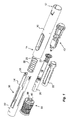
図面に示す薬剤送達装置は、遠位端部12および近位端部14を有する、略筒状で縦長の筐体10を備える(図1)。筐体10は、さらに、薬剤容器18を視認できる窓部または開口部16とともに構成されている。薬剤容器18は、可動性ストッパ20とともに構成されている。装置は、さらに、略筒形状を有する薬剤容器ホルダ22を備える(図1)。薬剤容器ホルダ22は、薬剤容器18を収納するように構成され、薬剤容器18は、近位端部を有し、当該近位端部では、薬剤送達部材24が薬剤容器18と一体成型または接続可能に構成されている(図2aおよび図2b)。薬剤送達部材24は、図示された実施形態では、いわゆる剛性針シールドまたはRNSである薬剤送達部材シールド26によって使用前に保護されていることが好ましい。しかし、当然ながら、その他の種類の薬剤送達部材シールドを用いて薬剤送達部材24を所望に保護してもよい。
The drug delivery device shown in the drawings comprises a generally cylindrical, vertically
筐体の近位端部は、アクティベータ30が伸長する中央通路28(図1)とともに構成されている。本実施形態において、アクティベータ30は、略筒状の薬剤送達部材ガードである。薬剤送達部材ガード30は、本実施形態では、薬剤送達装置に含まれる駆動機構のアクティベーション機構である。薬剤送達部材ガード30は、筐体10に対してスライド可能に、すなわち、線形に可動に構成されており、薬剤送達装置が薬剤送達部位に押し付けられたときに、薬剤容器18および薬剤送達部材24が装填された筐体10が近位方向に動くようになっている。これによって、薬剤送達部材が注射針である場合、薬剤送達部材24が露出して、貫入が行われる。
The proximal end of the housing is configured with a central passage 28 (FIG. 1) through which the
アクティベータ30は、近位の筒状パーツ32と、筒状パーツ32から延在する、遠位方向に向いた2つのアーム34とを備える。アクティベータ30の遠位方向に向いた周壁部分と筐体の近位方向に向いた周面との間には、薬剤送達部材ガード用ばね35が構成されている。アーム34は、薬剤容器ホルダ22に沿ってスライド可能に構成されている。アーム34の遠位端には、内向きの凸部36が構成されている。凸部36は、筐体に対してアクティベータ30が動かされたときに、薬剤送達装置に含まれる駆動機構の回転子38(図3および図4)と操作可能に相互に作用し合うように構成されており、回転子38は、薬剤容器18の遠位に位置する。
The
回転子38は、略筒形状を有し、案内隆起部42とともに構成されている(図4)。案内隆起部42は、アクティベータ30の凸部36と協働するためのものである。案内隆起部は、装置の長手方向の軸Lに対して傾斜した第1案内隆起部42iを備え、傾斜した第1案内隆起部42iは、図4からわかるように、丸みのある第2案内隆起部42rと相互に連結されており、第2案内隆起部42rは、長手方向の軸Lを概ね横断している。第2案内隆起部には第3案内隆起部42lが接続されており、第3案内隆起部42lは、長手方向に延在している。案内隆起部の機能については後述する。第3案内隆起部42lの近傍に位置するのは、近位方向に向いた舌部44であり、舌部44は、くさび形の外向きの突起46とともに構成されている。さらに、回転子は、遠位端の表面が切欠き48とともに構成されている。回転子の内部には、支持面50が構成されている。回転子38の内部には、さらに、方向付け要素が、縦溝51の形で、遠位端からほぼ近位端まで構成されている。しかし、溝51は、近位端からの距離をあけて終端をなしている。縦溝方向における近位端の端部には、停止凹部を形成する切欠き53が作られている。
The
アクチュエータ52(図3および図5)は、本実施形態では、薬剤送達装置に含まれる駆動機構の一部である。アクチュエータ52は、さらに、回転子38に対して操作可能に構成されている。アクチュエータ52は、回転子38の内径よりもわずかに小さい直径を有する、近位の筒状の第1部分54を備える。アクチュエータ52は、さらに、筐体10の遠位部に嵌め込まれて取り付けられるように構成された第2部分56を備える。後述するが、第2部分56には、回転子と相互に作用し合うように構成された、近位方向に向いた突起58が設けられている。第2部分は、さらに、近位方向に向いた停止面59とともに構成されている(図5)。
In this embodiment, the actuator 52 (FIGS. 3 and 5) is a part of a drive mechanism included in the drug delivery device. The
第1部分54は、さらに、保持部材60とともに構成されており、本実施形態では、保持部材60は、略径方向に可撓性を有するように構成された、近位方向に延在するアームである。後述するが、保持部材60の自由端部は、回転子38の支持面50と相互に作用し合う、外向きに延在する凸部62を有する。さらに、保持部材60の自由端部は、内向きに延在する凸部64とともに構成されており、凸部64は、略筒状のプランジャーロッド68の凹部66と相互に作用し合うようになっている(図3)。略筒状のプランジャーロッド68は、本実施形態では、薬剤送達装置に含まれる駆動機構の一部である。凸部64は、アクチュエータ52の中央通路70内まで延在し、通路70にはプランジャーロッド68が嵌合する。さらに、略くさび形の外向きの凸部71が、通路70の近傍に構成されている。
The
本実施形態では薬剤送達装置に含まれる駆動機構の一部である駆動用ばね72は、中空プランジャーロッド68の空洞内に載置され、駆動用ばね72は、近位端部がプランジャーロッド68の端壁74と接触した状態で配置されている(図2)。駆動用ばね72の遠位端は、略U形状の要素(以下、アクティベータ76と呼ぶ)と接触しており、基部78および2つのアーム80を有する(図3)。アクティベータ76のアーム80は、プランジャーロッド68の外面に沿って近位方向に向けられ、かつプランジャーロッド68の外面と接しており、アーム80の自由端部は、略径方向外向きの突起82とともに構成されている。これらの突起82は、近位方向に向いた表面84と接するように構成され(図5)、アクチュエータ52の中央通路70を取り囲んでいる。
In this embodiment, the
薬剤送達装置は、さらに、筐体の近位端に解放可能に取り付けられる形状を有する保護キャップ86とともに構成されている(図1および図2)。保護キャップ86は、さらに、薬剤送達部材シールド除去部材88とともに構成されており、図示された実施形態では、薬剤送達部材シールド除去部材88は、アクティベータの内部まで延在して薬剤送達部材シールド26を取り囲むような直径を有する略筒形状である。薬剤送達部材シールド除去部材88は、内向きに傾斜した把持要素90および近位方向に向いた舌部とともに構成されており、舌部は、保護キャップが薬剤送達装置に対して近位方向に引っ張られると、薬剤送達部材シールドの表面をしっかり掴めるようになっている。
The drug delivery device is further configured with a
装置は、以下のように機能するようになっている。薬剤送達装置がユーザに届けられたとき、薬剤容器18は、薬剤送達部材シールド26が取り付けられた状態で、薬剤容器ホルダ22内に載置されており、保護キャップは、薬剤送達装置の近位端に取り付けられている。駆動用ばね72は伸長状態であり、アクチュエータ52の保持部材60の内向きの凸部64がプランジャーロッド68の凹部66と係合するように、プランジャーロッド68がアクチュエータ52から遠位方向に押されており、プランジャーロッド68はこのようにして保持されている。
The device functions as follows. When the drug delivery device is delivered to the user, the
次に、回転子38が近位端からアクチュエータ52に対して軸方向に押される。アクチュエータ52に対して回転子が正しい回転方向になるために、方向付け要素、すなわち、凸部71が回転子38の縦溝51に嵌め込まれるように、回転子38が保持される。次に、凸部71が切欠き53に嵌め込まれるまで回転子38が軸方向に押される。これによって、回転子38が引き戻されるのを防ぐ。第1の位置と称するこの回転位置では、図6からわかるように、回転子38の遠位方向に向いた端部がアクチュエータ52の突起58に接触している。アクチュエータ52の保持部材60は、このとき、保持部材60の外向きの凸部62と接触している回転子38の支持面50による係合から外れないようになっている。
Next, the
1回の投与量の薬剤が送達されるとき、保護キャップ86は、近位方向に引っ張られることによって、薬剤送達装置の近位端から取り外される。舌部90が薬剤送達部材シールド26と係合しているため、薬剤送達部材シールド26も近位方向に引っ張られて、薬剤送達部材24から取り外される。次に、薬剤送達装置の近位端が投与量送達部位に押し付けられる。これによって、アクティベータ30が筐体10内で筐体10に対して動く。これによって今度は、アクティベータ30の凸部36が、回転子38の第1案内隆起部42iと接触するように、案内隆起部42に沿って動き、回転子38を装置の長手方向の軸Lを中心に回す、すなわち、回転させる。
When a single dose of drug is delivered, the
回転子38を回す/回転させることによって、図7からわかるように、凸部36が第2案内隆起部42rに到達するまで、回転子38の遠位方向に向いた端面が突起58に沿ってスライドする。同時に、この第2の位置において、回転子38の切欠き48が突起58に到達する(図8)ためアクティベータ30がさらに押されて、アクチュエータのアームの外向きの凸部に対して回転子38の支持面がスライドしながら、回転子38が軸方向に動かされる、すなわち、遠位方向に線形に転置される。回転子38の遠位方向に向いた端面がアクチュエータの近位方向に向いた停止面59に当接すると、回転子38の軸方向の動きが停止される。この第3位置において、アクチュエータ52の保持部材60の外向きの凸部62は、回転子38の近位端の表面(図9)を通り過ぎているため、凸部62の、回転子38の内面との接触が解除される。アクチュエータ52の保持部材60は、このとき、自由に外向きに撓むことができるため、保持部材60の内向きの凸部64の、プランジャーロッド68の凹部66との接触が解除される。
By the
保持部材60の撓みは素早く、保持部材60の外面が回転子38に当たることとなり、投与量送達シーケンスが開始されたことを示す聞き取り可能な触覚的合図を引き起こす。プランジャーロッド68は、このとき、駆動用ばね72の力によって近位方向に自由に動くことができるため、プランジャーロッド68の近位端が薬剤容器18内のストッパ20に作用し、1回の投与量の薬剤が薬剤送達部材24から押し出されるようにストッパ20を近位方向に動かす。
The deflection of the retaining
プランジャーロッド68によってストッパ20が薬剤容器18内でほぼ近位端まで動かされると、プランジャーロッド68の、合図要素76のアーム80との接触が解除される。したがって、合図要素76のアーム80は自由に内向きに撓むことができるようになり、突起82の、アクチュエータ52の面84との接触が解除される。合図要素76の基部78に接触して基部78に作用している駆動用ばね72の力によって、合図要素76は、遠位端部がアクチュエータの近位方向に向いた端壁に当たるまで、距離Dだけ遠位方向に急に動かされることになる。こうして、投与量送達シーケンスが完了したことと、薬剤送達装置を安全に部位から抜いてもよいこととを示す聞き取り可能な触覚的合図が与えられる。ここで、薬剤送達装置を安全に破棄することができる。
When the
上記に説明し、図に示した実施形態は、当然ながら、本発明の非限定例に過ぎず、特許請求の範囲内においていろいろな方法で変更されてもよい。 The embodiments described above and shown in the figures are, of course, only non-limiting examples of the invention and may be modified in various ways within the scope of the claims.
Claims (10)
プランジャーロッド(68)と、
前記プランジャーロッドに対して操作可能に構成された駆動用ばね(72)と、
伸長状態の前記駆動用ばね(72)を装填した前記プランジャーロッド(68)を保持するために前記プランジャーロッド(68)と解放可能に係合された保持部材(60)を備えるアクチュエータ(52)と、
前記アクチュエータ(52)に操作可能に接続され、前記アクチュエータ(52)に対して可動であり、前記保持部材を前記プランジャーロッドと係合した状態に保持するために、前記保持部材と相互に作用し合うように構成された回転子(38)と、
前記回転子(38)に操作可能に接続されるアクティベータ(30)とを備え、
前記アクティベータ(30)が長手方向に沿って移動することにより前記回転子(38)を第1の位置から第2の位置に前記長手方向の軸回りに回転させ、その後、前記アクティベータ(30)が前記長手方向に沿ってさらに移動することにより前記回転子(38)を前記アクチュエータ(52)に対して前記第2の位置から第3の位置に前記長手方向に沿って直線状に移動させるように前記アクティベータ(30)が構成され、
前記回転子(38)が前記第1の位置および前記第2の位置に配置されている状態では、前記保持部材(60)は前記プランジャーロッド(68)に係合しており、
前記回転子(38)が前記第3の位置に配置されている状態では、前記保持部材(60)は前記プランジャーロッド(68)との係合から解放されていることを特徴とする、駆動機構。 A drive mechanism for use in a drug delivery device comprising:
A plunger rod (68);
A drive spring (72) configured to be operable relative to the plunger rod;
An actuator (52) comprising a holding member (60) releasably engaged with the plunger rod (68) to hold the plunger rod (68) loaded with the drive spring (72) in an extended state. )When,
Operatively connected to the actuator (52), movable relative to the actuator (52), and interacting with the holding member to hold the holding member engaged with the plunger rod A rotor (38) configured to fit together;
An activator (30) operably connected to the rotor (38) ;
The activator (30) moves along the longitudinal direction to rotate the rotor (38) from a first position to a second position about the longitudinal axis , and then the activator (30). ) Further moves along the longitudinal direction to move the rotor (38) linearly along the longitudinal direction from the second position to the third position with respect to the actuator (52). The activator (30) is configured as follows :
In a state where the rotor (38) is disposed at the first position and the second position, the holding member (60) is engaged with the plunger rod (68),
In a state in which the rotor (38) is disposed in the third position, the retaining member (60) is characterized that you have been released from engagement with said plunger rod (68), the drive mechanism.
前記回転子(38)が前記第1の位置から前記第2の位置に回転される際、前記回転子(38)は前記突起(58)の上に載って回転している、請求項1に記載の駆動機構。 The actuator (52) has a protrusion (58) ,
The rotor (38) rests on the protrusion (58) and rotates when the rotor (38) is rotated from the first position to the second position. The drive mechanism described.
Applications Claiming Priority (3)
| Application Number | Priority Date | Filing Date | Title |
|---|---|---|---|
| SE1550496 | 2015-04-24 | ||
| SE1550496-2 | 2015-04-24 | ||
| PCT/EP2016/057342 WO2016169756A1 (en) | 2015-04-24 | 2016-04-04 | Drive mechanism for an autoinjector |
Publications (3)
| Publication Number | Publication Date |
|---|---|
| JP2018512973A JP2018512973A (en) | 2018-05-24 |
| JP2018512973A5 JP2018512973A5 (en) | 2018-07-05 |
| JP6567687B2 true JP6567687B2 (en) | 2019-08-28 |
Family
ID=55802341
Family Applications (1)
| Application Number | Title | Priority Date | Filing Date |
|---|---|---|---|
| JP2017555544A Active JP6567687B2 (en) | 2015-04-24 | 2016-04-04 | Automatic syringe drive mechanism |
Country Status (7)
| Country | Link |
|---|---|
| US (1) | US10881797B2 (en) |
| EP (1) | EP3285832A1 (en) |
| JP (1) | JP6567687B2 (en) |
| KR (1) | KR102016829B1 (en) |
| CN (1) | CN107635603B (en) |
| TW (1) | TWI630936B (en) |
| WO (1) | WO2016169756A1 (en) |
Families Citing this family (10)
| Publication number | Priority date | Publication date | Assignee | Title |
|---|---|---|---|---|
| EP2399635A1 (en) | 2010-06-28 | 2011-12-28 | Sanofi-Aventis Deutschland GmbH | Auto-injector |
| BR112022005836A2 (en) * | 2019-09-30 | 2022-06-21 | Amgen Inc | drug delivery device |
| US20220387719A1 (en) * | 2019-12-05 | 2022-12-08 | Shl Medical Ag | Feedback mechanisms |
| JP2023536501A (en) * | 2020-08-07 | 2023-08-25 | サノフイ | Apparatus for drug delivery device |
| CN118302212A (en) * | 2021-12-07 | 2024-07-05 | 艾斯曲尔医疗公司 | Sub-assembly of a medicament delivery device |
| WO2023151952A1 (en) * | 2022-02-08 | 2023-08-17 | Shl Medical Ag | A subassembly of a medicament delivery device |
| WO2024008491A1 (en) * | 2022-07-07 | 2024-01-11 | Shl Medical Ag | A sub-assembly of a medicament delivery device |
| WO2024022643A1 (en) * | 2022-07-26 | 2024-02-01 | Shl Medical Ag | Cap for medicament delivery device |
| KR102682087B1 (en) * | 2023-03-08 | 2024-07-05 | 주식회사 비에스엘 | Auto-injector |
| KR102694740B1 (en) * | 2023-03-29 | 2024-08-14 | 주식회사 비에스엘 | Auto-injector |
Family Cites Families (9)
| Publication number | Priority date | Publication date | Assignee | Title |
|---|---|---|---|---|
| GB2414402B (en) * | 2004-05-28 | 2009-04-22 | Cilag Ag Int | Injection device |
| JP5238804B2 (en) * | 2007-06-04 | 2013-07-17 | ベクトン・ディキンソン・アンド・カンパニー | Positive movement stopper for prefilled syringe |
| KR101724784B1 (en) * | 2010-03-31 | 2017-04-07 | 에스에이치엘 그룹 에이비 | Medicament delivery device |
| UA109548C2 (en) * | 2010-07-02 | 2015-09-10 | Ітеро Байофармасьютікалз, Інк. | Device for the self-injection of the solution of the follicle-stimulating hormone, which does not contain the preserving agent |
| GB201020472D0 (en) * | 2010-12-02 | 2011-01-19 | Oval Medical Technologies Ltd | A drive assembly for an autoinjector |
| EP2665503B1 (en) * | 2011-01-11 | 2024-01-24 | SHL Medical AG | Medicament delivery device |
| PL2694141T3 (en) * | 2011-04-05 | 2020-11-02 | Shl Medical Ag | Medicament delivery device comprising a locking mechanism having a lever |
| CH705345A2 (en) * | 2011-08-04 | 2013-02-15 | Tecpharma Licensing Ag | Injector with needle protection device. |
| CN112870489B (en) * | 2015-04-24 | 2022-12-06 | 艾斯曲尔医疗公司 | Sub-assembly of a medicament delivery device and medicament delivery device |
-
2016
- 2016-04-04 US US15/568,816 patent/US10881797B2/en active Active
- 2016-04-04 EP EP16717582.7A patent/EP3285832A1/en active Pending
- 2016-04-04 JP JP2017555544A patent/JP6567687B2/en active Active
- 2016-04-04 KR KR1020177033851A patent/KR102016829B1/en active IP Right Grant
- 2016-04-04 WO PCT/EP2016/057342 patent/WO2016169756A1/en active Application Filing
- 2016-04-04 CN CN201680028458.5A patent/CN107635603B/en active Active
- 2016-04-12 TW TW105111382A patent/TWI630936B/en active
Also Published As
| Publication number | Publication date |
|---|---|
| TW201707739A (en) | 2017-03-01 |
| KR102016829B1 (en) | 2019-08-30 |
| US10881797B2 (en) | 2021-01-05 |
| JP2018512973A (en) | 2018-05-24 |
| WO2016169756A1 (en) | 2016-10-27 |
| EP3285832A1 (en) | 2018-02-28 |
| CN107635603B (en) | 2020-09-01 |
| KR20170139636A (en) | 2017-12-19 |
| TWI630936B (en) | 2018-08-01 |
| US20180104415A1 (en) | 2018-04-19 |
| CN107635603A (en) | 2018-01-26 |
Similar Documents
| Publication | Publication Date | Title |
|---|---|---|
| JP6567687B2 (en) | Automatic syringe drive mechanism | |
| JP6774877B2 (en) | Automatic injection device | |
| JP5847316B2 (en) | Medical delivery device having an initial locked state, an intermediate starting ready state and a drug delivery state | |
| JP6100840B2 (en) | Injection device | |
| TWI569835B (en) | Medicament delivery device | |
| JP5531144B2 (en) | Drug delivery device with feedback signal transmission means | |
| US10525213B2 (en) | Medicament delivery device | |
| KR101976299B1 (en) | Dose setting mechanism and medicament delivery device comprising the dose setting mechanism | |
| JP2017517311A (en) | Drug delivery device having a rotating machine holding a plunger rod | |
| JP2018537251A (en) | Drug delivery device | |
| JP2019500991A (en) | Automatic syringe with cartridge retention system | |
| JP2007512932A (en) | Pharmaceutical supply device having air shot means | |
| JP2014526356A (en) | Needle safety device | |
| TWI646993B (en) | Power pack | |
| CN107427643B (en) | Drug delivery device | |
| US20170246400A1 (en) | Delivery Device | |
| JP2019535411A (en) | Drug delivery device suitable for long-term storage | |
| EP3423131B1 (en) | Automatic delivery device with end of injection indication device | |
| US11065390B2 (en) | Automatic delivery device with end of injection indication device | |
| TWI629080B (en) | Medicament delivery device | |
| US11612700B2 (en) | Delivery device |
Legal Events
| Date | Code | Title | Description |
|---|---|---|---|
| A621 | Written request for application examination |
Free format text: JAPANESE INTERMEDIATE CODE: A621 Effective date: 20171221 |
|
| A521 | Request for written amendment filed |
Free format text: JAPANESE INTERMEDIATE CODE: A523 Effective date: 20180410 |
|
| A977 | Report on retrieval |
Free format text: JAPANESE INTERMEDIATE CODE: A971007 Effective date: 20181119 |
|
| A131 | Notification of reasons for refusal |
Free format text: JAPANESE INTERMEDIATE CODE: A131 Effective date: 20181127 |
|
| A521 | Request for written amendment filed |
Free format text: JAPANESE INTERMEDIATE CODE: A523 Effective date: 20190227 |
|
| A711 | Notification of change in applicant |
Free format text: JAPANESE INTERMEDIATE CODE: A711 Effective date: 20190419 |
|
| TRDD | Decision of grant or rejection written | ||
| A01 | Written decision to grant a patent or to grant a registration (utility model) |
Free format text: JAPANESE INTERMEDIATE CODE: A01 Effective date: 20190709 |
|
| A61 | First payment of annual fees (during grant procedure) |
Free format text: JAPANESE INTERMEDIATE CODE: A61 Effective date: 20190731 |
|
| R150 | Certificate of patent or registration of utility model |
Ref document number: 6567687 Country of ref document: JP Free format text: JAPANESE INTERMEDIATE CODE: R150 |
|
| R250 | Receipt of annual fees |
Free format text: JAPANESE INTERMEDIATE CODE: R250 |
|
| R250 | Receipt of annual fees |
Free format text: JAPANESE INTERMEDIATE CODE: R250 |
|
| R250 | Receipt of annual fees |
Free format text: JAPANESE INTERMEDIATE CODE: R250 |