JP6567100B2 - Method, apparatus, and system for encoding and decoding transform unit of encoding unit - Google Patents
Method, apparatus, and system for encoding and decoding transform unit of encoding unit Download PDFInfo
- Publication number
- JP6567100B2 JP6567100B2 JP2018009529A JP2018009529A JP6567100B2 JP 6567100 B2 JP6567100 B2 JP 6567100B2 JP 2018009529 A JP2018009529 A JP 2018009529A JP 2018009529 A JP2018009529 A JP 2018009529A JP 6567100 B2 JP6567100 B2 JP 6567100B2
- Authority
- JP
- Japan
- Prior art keywords
- transform
- color difference
- chrominance
- unit
- residual
- Prior art date
- Legal status (The legal status is an assumption and is not a legal conclusion. Google has not performed a legal analysis and makes no representation as to the accuracy of the status listed.)
- Active
Links
Images


Classifications
-
- H—ELECTRICITY
- H04—ELECTRIC COMMUNICATION TECHNIQUE
- H04N—PICTORIAL COMMUNICATION, e.g. TELEVISION
- H04N19/00—Methods or arrangements for coding, decoding, compressing or decompressing digital video signals
- H04N19/10—Methods or arrangements for coding, decoding, compressing or decompressing digital video signals using adaptive coding
- H04N19/102—Methods or arrangements for coding, decoding, compressing or decompressing digital video signals using adaptive coding characterised by the element, parameter or selection affected or controlled by the adaptive coding
- H04N19/12—Selection from among a plurality of transforms or standards, e.g. selection between discrete cosine transform [DCT] and sub-band transform or selection between H.263 and H.264
- H04N19/122—Selection of transform size, e.g. 8x8 or 2x4x8 DCT; Selection of sub-band transforms of varying structure or type
-
- G—PHYSICS
- G06—COMPUTING; CALCULATING OR COUNTING
- G06T—IMAGE DATA PROCESSING OR GENERATION, IN GENERAL
- G06T9/00—Image coding
- G06T9/40—Tree coding, e.g. quadtree, octree
-
- H—ELECTRICITY
- H04—ELECTRIC COMMUNICATION TECHNIQUE
- H04N—PICTORIAL COMMUNICATION, e.g. TELEVISION
- H04N19/00—Methods or arrangements for coding, decoding, compressing or decompressing digital video signals
- H04N19/10—Methods or arrangements for coding, decoding, compressing or decompressing digital video signals using adaptive coding
- H04N19/102—Methods or arrangements for coding, decoding, compressing or decompressing digital video signals using adaptive coding characterised by the element, parameter or selection affected or controlled by the adaptive coding
- H04N19/119—Adaptive subdivision aspects, e.g. subdivision of a picture into rectangular or non-rectangular coding blocks
-
- H—ELECTRICITY
- H04—ELECTRIC COMMUNICATION TECHNIQUE
- H04N—PICTORIAL COMMUNICATION, e.g. TELEVISION
- H04N19/00—Methods or arrangements for coding, decoding, compressing or decompressing digital video signals
- H04N19/10—Methods or arrangements for coding, decoding, compressing or decompressing digital video signals using adaptive coding
- H04N19/134—Methods or arrangements for coding, decoding, compressing or decompressing digital video signals using adaptive coding characterised by the element, parameter or criterion affecting or controlling the adaptive coding
- H04N19/136—Incoming video signal characteristics or properties
-
- H—ELECTRICITY
- H04—ELECTRIC COMMUNICATION TECHNIQUE
- H04N—PICTORIAL COMMUNICATION, e.g. TELEVISION
- H04N19/00—Methods or arrangements for coding, decoding, compressing or decompressing digital video signals
- H04N19/10—Methods or arrangements for coding, decoding, compressing or decompressing digital video signals using adaptive coding
- H04N19/169—Methods or arrangements for coding, decoding, compressing or decompressing digital video signals using adaptive coding characterised by the coding unit, i.e. the structural portion or semantic portion of the video signal being the object or the subject of the adaptive coding
- H04N19/18—Methods or arrangements for coding, decoding, compressing or decompressing digital video signals using adaptive coding characterised by the coding unit, i.e. the structural portion or semantic portion of the video signal being the object or the subject of the adaptive coding the unit being a set of transform coefficients
-
- H—ELECTRICITY
- H04—ELECTRIC COMMUNICATION TECHNIQUE
- H04N—PICTORIAL COMMUNICATION, e.g. TELEVISION
- H04N19/00—Methods or arrangements for coding, decoding, compressing or decompressing digital video signals
- H04N19/10—Methods or arrangements for coding, decoding, compressing or decompressing digital video signals using adaptive coding
- H04N19/169—Methods or arrangements for coding, decoding, compressing or decompressing digital video signals using adaptive coding characterised by the coding unit, i.e. the structural portion or semantic portion of the video signal being the object or the subject of the adaptive coding
- H04N19/186—Methods or arrangements for coding, decoding, compressing or decompressing digital video signals using adaptive coding characterised by the coding unit, i.e. the structural portion or semantic portion of the video signal being the object or the subject of the adaptive coding the unit being a colour or a chrominance component
-
- H—ELECTRICITY
- H04—ELECTRIC COMMUNICATION TECHNIQUE
- H04N—PICTORIAL COMMUNICATION, e.g. TELEVISION
- H04N19/00—Methods or arrangements for coding, decoding, compressing or decompressing digital video signals
- H04N19/44—Decoders specially adapted therefor, e.g. video decoders which are asymmetric with respect to the encoder
-
- H—ELECTRICITY
- H04—ELECTRIC COMMUNICATION TECHNIQUE
- H04N—PICTORIAL COMMUNICATION, e.g. TELEVISION
- H04N19/00—Methods or arrangements for coding, decoding, compressing or decompressing digital video signals
- H04N19/60—Methods or arrangements for coding, decoding, compressing or decompressing digital video signals using transform coding
- H04N19/61—Methods or arrangements for coding, decoding, compressing or decompressing digital video signals using transform coding in combination with predictive coding
-
- H—ELECTRICITY
- H04—ELECTRIC COMMUNICATION TECHNIQUE
- H04N—PICTORIAL COMMUNICATION, e.g. TELEVISION
- H04N19/00—Methods or arrangements for coding, decoding, compressing or decompressing digital video signals
- H04N19/90—Methods or arrangements for coding, decoding, compressing or decompressing digital video signals using coding techniques not provided for in groups H04N19/10-H04N19/85, e.g. fractals
- H04N19/96—Tree coding, e.g. quad-tree coding
-
- H—ELECTRICITY
- H04—ELECTRIC COMMUNICATION TECHNIQUE
- H04N—PICTORIAL COMMUNICATION, e.g. TELEVISION
- H04N19/00—Methods or arrangements for coding, decoding, compressing or decompressing digital video signals
- H04N19/10—Methods or arrangements for coding, decoding, compressing or decompressing digital video signals using adaptive coding
- H04N19/169—Methods or arrangements for coding, decoding, compressing or decompressing digital video signals using adaptive coding characterised by the coding unit, i.e. the structural portion or semantic portion of the video signal being the object or the subject of the adaptive coding
- H04N19/17—Methods or arrangements for coding, decoding, compressing or decompressing digital video signals using adaptive coding characterised by the coding unit, i.e. the structural portion or semantic portion of the video signal being the object or the subject of the adaptive coding the unit being an image region, e.g. an object
- H04N19/176—Methods or arrangements for coding, decoding, compressing or decompressing digital video signals using adaptive coding characterised by the coding unit, i.e. the structural portion or semantic portion of the video signal being the object or the subject of the adaptive coding the unit being an image region, e.g. an object the region being a block, e.g. a macroblock
-
- H—ELECTRICITY
- H04—ELECTRIC COMMUNICATION TECHNIQUE
- H04N—PICTORIAL COMMUNICATION, e.g. TELEVISION
- H04N19/00—Methods or arrangements for coding, decoding, compressing or decompressing digital video signals
- H04N19/70—Methods or arrangements for coding, decoding, compressing or decompressing digital video signals characterised by syntax aspects related to video coding, e.g. related to compression standards
Description
本出願は、2012年9月28日に出願されたオーストラリア国特許出願第2012232992号の出願日の権利を米国特許法第119条の下で主張し、本明細書において十分に示されるようにその全体を参考文献として援用する。 This application claims the date of filing of Australian Patent Application No. 20121232992 filed on September 28, 2012 under 35 USC 119, as fully set forth herein. The whole is incorporated by reference.
本発明は、一般的に、デジタルビデオ信号処理に関し、特に、変換単位(TU)の残差係数を符号化し復号化するための方法、装置およびシステムに関する。ここで、変換単位(TU)は、1つ以上の変換単位(TU)を含み、4:2:2色差フォーマットを含む複数の色差フォーマット用に構成されてもよい。 The present invention relates generally to digital video signal processing, and more particularly to a method, apparatus and system for encoding and decoding transform unit (TU) residual coefficients. Here, the conversion unit (TU) includes one or more conversion units (TU), and may be configured for a plurality of color difference formats including a 4: 2: 2 color difference format.
現在、ビデオデータの伝送および記憶のためのアプリケーションを含む、ビデオ符号化のための多くのアプリケーションが存在する。多くのビデオ符号化規格も開発されていて、他の規格も現在開発中である。ビデオ符号化の規格化における最近の展開は、「映像符号化共同研究部会」(JCT−VC)と呼ばれるグループの形成に結びついた。映像符号化共同研究部会(JCT−VC)は、映像符号化専門家グループ(VCEG)として知られている国際電気通信連合(ITU)の電気通信標準化部門(ITU−T)の第16研究グループQuestion6(SG16/Q6)のメンバーと、動画専門家グループ(MPEG)として知られている国際標準化機構/国際電気標準会議第一合同技術委員会/小委員会29/作業部会11(ISO/IEC JTC1/SC29/WG11)のメンバーとを含む。
Currently, there are many applications for video encoding, including applications for transmission and storage of video data. Many video coding standards have been developed, and other standards are currently under development. Recent developments in the standardization of video coding have led to the formation of a group called the “Video Coding Joint Research Group” (JCT-VC). The Video Coding Joint Research Group (JCT-VC) is the 16th
映像符号化共同研究部会(JCT−VC)は、「H.264/MPEG−4 AVC」として知られている現存するビデオ符号化規格よりも著しく性能が優れている新規のビデオ符号化規格を生み出すことを目標とする。H.264/MPEG−4 AVC規格は、それ自体、従来のビデオ符号化規格(MPEG−4およびITU−T H.263)に対する大規模な改良である。開発中の新規のビデオ符号化規格は「高効率動画像符号化方式(HEVC)」と命名された。映像符号化共同研究部会JCT−VCは、また、リアルタイムまたは高フレームレートにおいて高分解能で動作する規格の実施態様をスケーリングする際に困難さが生じる高効率動画像符号化方式(HEVC)のために提案された技術から生じる実施課題を検討している。1つの実施課題は、周波数領域と空間領域との間でビデオデータを変換するための複数「変換」サイズサポートするために用いられるロジックの複雑性およびサイズである。 Video Coding Joint Research Group (JCT-VC) produces a new video coding standard that is significantly better than the existing video coding standard known as “H.264 / MPEG-4 AVC” The goal is to. H. The H.264 / MPEG-4 AVC standard is itself a major improvement over conventional video coding standards (MPEG-4 and ITU-T H.263). The new video coding standard under development has been named “Highly Efficient Video Coding (HEVC)”. The Video Coding Joint Research Group JCT-VC is also working for a high-efficiency video coding scheme (HEVC) that creates difficulties in scaling implementations of standards that operate at high resolution in real time or at high frame rates. Implementation issues arising from the proposed technology are being considered. One implementation challenge is the complexity and size of the logic used to support multiple “transform” sizes for transforming video data between the frequency domain and the spatial domain.
本発明は、既存の仕組みの1つ以上の短所を、実質的に克服するか、または少なくとも改善することを目的とする。
本開示の1つの態様によれば、ビデオビットストリームから、4:2:2フォーマットの符号化単位内の変換単位に含まれる、2つの色差チャネルにそれぞれ関連付けられた2つの色差残差係数配列を復号し、前記復号された色差残差係数配列を周波数領域から空間領域の色差残差サンプルへ変換する方法であって、
符号化単位のサイズおよび前記符号化単位内の変換単位の階層レベルに従って、正方形ブロックで表される前記変換単位の変換サイズを決定するステップと、
各色差チャンネルにおいて、
前記ビデオビットストリームから、前記変換単位が有する2つの色差残差係数配列のそれぞれに対応する2つの符号化ブロックフラグ値を復号するステップと、
前記2つの符号化ブロックフラグ値のうちの対応する符号化ブロックフラグ値に従って、前記2つの色差残差係数配列の各々を前記ビデオビットストリームから復号するステップと、
前記決定された変換サイズに対応する正方形ブロックのための変換を、前記復号された色差残差係数配列の各々に対して適用することにより、色差残差サンプルを生成するステップと、
を備え、
前記2つの色差残差係数配列の各々を前記ビデオビットストリームから復号するステップにおいて、前記2つの色差残差係数配列の各々に対して同じスキャンパターンを適用することにより、正方形ブロックで表される前記決定された変換サイズの変換単位を生成することを特徴とする方法が提供される。
他の態様も開示される。
The present invention aims to substantially overcome or at least ameliorate one or more disadvantages of existing mechanisms.
According to one aspect of the present disclosure, two color difference residual coefficient arrays respectively associated with two color difference channels included in a transform unit in a 4: 2: 2 format coding unit are obtained from a video bitstream. Decoding and transforming the decoded chrominance residual coefficient array from a frequency domain to a spatial domain chrominance residual sample, comprising:
Determining a transform size of the transform unit represented by a square block according to the size of the coding unit and the hierarchical level of the transform unit within the coding unit;
In each color difference channel
Decoding two encoded block flag values corresponding to each of the two color difference residual coefficient arrays of the transform unit from the video bitstream;
Decoding each of the two chrominance residual coefficient arrays from the video bitstream according to a corresponding encoded block flag value of the two encoded block flag values;
Generating a chrominance residual sample by applying a transform for a square block corresponding to the determined transform size to each of the decoded chrominance residual coefficient arrays;
With
In the step of decoding each of the two chrominance residual coefficient arrays from the video bitstream, by applying the same scan pattern to each of the two chrominance residual coefficient arrays, A method is provided that generates a transform unit of a determined transform size .
Other aspects are also disclosed.
ここで、本発明の少なくとも1つの実施形態が、以下の図面を参照しながら記載されることになる。
添付の図面のいずれか1つ以上において、同一の参照符号を有するステップおよび/または特徴を参照する場合、それらのステップおよび/または特徴は、別段の意図が示されている場合を除いて、この記述にとって同一の機能または動作を有する。 When reference is made to steps and / or features having the same reference sign in any one or more of the accompanying drawings, these steps and / or features are not indicated unless otherwise indicated. Has the same function or behavior for the description.
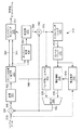
図1は、色差チャネルのために変換単位を複数の変換に暗黙的に細分割(inferred subdivision)することを表現するコード化構文要素のための技術を利用できるビデオ符号化/復号化システム100の関数モジュールを示す概略ブロック図である。システム100は、ソース装置110と宛先装置130とを含む。通信チャネル120は、ソース装置110から宛先装置130に符号化映像情報を通信するために用いられる。いくつかのケースにおいて、ソース装置110および宛先装置130は、それぞれの携帯電話ハンドセットを備えてもよく、その場合、通信チャネル120は、無線チャネルである。他のケースにおいて、ソース装置110および宛先装置130は、ビデオ会議装置を備えてもよく、その場合、通信チャネル120は、通常はインターネット接続などの有線チャネルである。さらに、ソース装置110および宛先装置130は、テレビ放送、ケーブルテレビアプリケーション、インターネットビデオアプリケーションをサポートする装置を含み、符号化ビデオがいくつかの記憶媒体またはファイルサーバ上で取り込まれるアプリケーションを含む、任意の広範囲の装置を備えてもよい。
FIG. 1 illustrates a video encoding /
図示するように、ソース装置110は、ビデオソース112と、ビデオエンコーダ114と、送信器116とを含む。ビデオソース112は、通常は、撮像センサ、非一時的な記録媒体に記憶された予め取り込まれたビデオシーケンス、またはリモート撮像センサから供給されたビデオなどの、取り込まれたビデオフレームデータのソースを備える。ビデオソース112のような撮像センサを含んでもよいソース装置110の例は、スマートフォン、ビデオカムコーダ、およびネットワークビデオカメラを含む。ビデオエンコーダ114は、ビデオソース112から取り込まれたフレームデータを符号化ビデオデータに変換し、図3を参照しながらさらに記述されることになる。符号化ビデオデータは、通常は、符号化ビデオ情報として通信チャネル120を通じて送信器116によって送信される。また、符号化ビデオデータは、後で通信チャネル120を通じて送信されるまでは、「フラッシュ」メモリまたはハードディスクドライブなどの何らかの記憶装置に記憶されることも可能である。
As shown,
宛先装置130は、受信器132と、ビデオデコーダ134と、ディスプレイ装置136とを含む。受信器132は、通信チャネル120から符号化ビデオ情報を受信し、受信されたビデオデータをビデオデコーダ134に渡す。その後、ビデオデコーダ134は、ディスプレイ装置136に対して復号化フレームデータを出力する。ディスプレイ装置136の例は、スマートフォン、タブレット型コンピュータ、コンピュータ用モニタ内の、またはスタンドアロン型テレビジョンセット内の、ブラウン管、液晶ディスプレイを含む。また、ソース装置110および宛先装置130の各々の機能性にとって、単一の装置で具体化されることも可能である。
The
上述の例示的な装置にもかかわらず、ソース装置110および宛先装置130の各々は、汎用コンピューティングシステム内で、通常は、ハードウェアおよびソフトウェアコンポーネントの組み合わせを通じて構成されてもよい。図2Aは、このようなコンピュータシステム200を図示しており、コンピュータシステム200は、コンピュータモジュール201と、キーボード202、マウスポインタ装置203、スキャナ226、ビデオソース112として構成されてもよいカメラ227、およびマイクロホン280などの入力装置と、およびプリンタ215、ディスプレイ装置136として構成されてもよいディスプレイ装置214、およびスピーカ217を含む出力装置とを含む。外部変調器復調器(モデム)トランシーバ装置216は、接続221を介して通信ネットワーク220間で通信するためにコンピュータモジュール201によって用いられてもよい。通信チャネル120に相当してもよい通信ネットワーク220は、インターネット、セルラ電気通信ネットワーク、またはプライベートWANなどのワイドエリアネットワーク(WAN)であってもよい。接続221が電話線である場合、モデム216は、従来の「ダイアルアップ」モデムであってもよい。または、接続221が高容量(例えばケーブル)接続である場合、モデム216は、ブロードバンドモデムであってもよい。無線モデムも、また、通信ネットワーク220に対する無線接続のために用いられてもよい。トランシーバ装置216は、送信器116および受信器132の機能性を提供してもよく。通信チャネル120は、接続221において具体化されてもよい。
Despite the exemplary devices described above, each of
コンピュータモジュール201は、通常は、少なくとも1つのプロセッサー205と、メモリユニット206とを含む。例えば、メモリユニット206は、半導体ランダムアクセスメモリ(RAM)と半導体読み取り専用メモリ(ROM)とを有してもよい。コンピュータモジュール201は、また、ビデオディスプレイ214、スピーカ217、およびマイクロホン280に連結されるオーディオビデオインタフェース207と、キーボード202、マウス203、スキャナ226、カメラ227、および必要に応じてジョイスティック、または他のヒューマンインタフェース装置(図示せず)に連結されるI/Oインタフェース213と、外部モデム216およびプリンタ215のためのインタフェース208とを含むいくつかの入出力(I/O)インタフェースを含む。いくつかの実施態様において、モデム216は、コンピュータモジュール201内に、例えばインタフェース208内に、組み込まれてもよい。コンピュータモジュール201は、また、ローカルエリアネットワーク(LAN)として知られているローカルエリア通信ネットワーク222に対する接続223を介してコンピュータシステム200の連結を可能にする、ローカルネットワークインタフェース211を有する。図2Aに図示されるように、ローカル通信ネットワーク222は、また、接続224を介してワイドネットワーク220に連結されてもよく、通常はいわゆる「ファイアウォール」装置または同様の機能性の装置を含むであろう。ローカルネットワークインタフェース211は、Ethernet(登録商標)回路カード、Bluetooth(登録商標)無線設備、またはIEEE802.11無線設備を備えてもよいが、但し、多数の他のタイプのインタフェースが、インタフェース211のために実施されてもよい。ローカルネットワークインタフェース211は、また、送信器116および受信器132の機能性を提供してもよく、通信チャネル120も、また、ローカル通信ネットワーク222において具体化されてもよい。
The
I/Oインタフェース208、213は、シリアル接続およびパラレル接続のいずれか一方若しくは双方を利用してもよく、前者は、通常は、ユニバーサルシリアルバス(USB)規格によって実施され、対応するUSBコネクタ(不図示)を有する。記憶装置209が設けられ、通常はハードディスクドライブ(HDD)210を含む。フロッピー(登録商標)ディスクドライブや磁気テープドライブ(不図示)などの他の記憶装置も、また、用いられてもよい。光ディスクドライブ212は、通常は、不揮発性のデータソースとして機能するために備えられる。ポータブルメモリ装置、このような光ディスク(例えばCD−ROM、DVD、ブルーレイディスク(商標))、USB−RAM、ポータブルな外部ハードドライブ、およびフロッピー(登録商標)ディスクは、例えば、コンピュータシステム200に対する適切なデータソースとして用いられてもよい。通常は、HDD210、光ドライブ212、ネットワーク220、222のいずれかは、ディスプレイ214を介した再生のために記憶された復号化ビデオデータのための、ビデオソース112として、または送信先として、動作するように構成されてもよい。
The I / O interfaces 208 and 213 may use either one or both of serial connection and parallel connection. The former is usually implemented by the universal serial bus (USB) standard and has a corresponding USB connector (not connected). As shown). A
コンピュータモジュール201のコンポーネント205〜213は、通常は、相互接続バス204を介して、および関連する当該技術分野のものに対して既知のコンピュータシステム200の従来のオペレーションモードをもたらす方式で、通信する。例えば、プロセッサー205は、接続218を用いて、システムバス204に連結される。同様に、メモリ206および光ディスクドライブ212は、接続219によってシステムバス204に連結される。記載の設備が実行され得るコンピュータの例は、IBM PCおよびその互換機、サン・マイクロシステムズのスパークステーション、アップル社のMac(商標)、または同様のコンピュータシステムを含む。
The components 205-213 of the
妥当若しくは所望の場合、ビデオエンコーダ114およびビデオデコーダ134は、下記の方法だけでなく、コンピュータシステム200を用いて実施されてもよく、ここで、ビデオエンコーダ114、ビデオデコーダ134、および後述の図10〜図13の処理は、コンピュータシステム200内で実行可能な1つ以上のソフトウェアアプリケーションプログラム233として実施されてもよい。特に、ビデオエンコーダ114、ビデオデコーダ134、および記載の方法のステップは、コンピュータシステム200内で実行されるソフトウェア233内の命令231(図2Bを参照)によって達成される。ソフトウェア命令231は、1つ以上の特定のタスクを各々実行するために、1つ以上のコードモジュールとして形成されてもよい。ソフトウェアは2つの部分に分かれていてもよく、第1の部分および対応するコードモジュールは、記載の方法を実行し、第2の一部および対応するコードモジュールは、第1の部分とユーザとの間のユーザインタフェースを管理する。
Where appropriate or desired,
ソフトウェアは、例えば下記の記憶装置を含むコンピュータ読み取り可能媒体内に記憶されてもよい。ソフトウェアは、コンピュータ読み取り可能媒体からコンピュータシステム200内にロードされ、その後、コンピュータシステム200によって実行される。コンピュータ読み取り可能媒体に記録されたこのようなソフトウェアまたはコンピュータプログラムを有するコンピュータ読み取り可能媒体は、コンピュータプログラムプロダクトである。コンピュータシステム200内のコンピュータプログラムプロダクトの使用は、ビデオエンコーダ114、ビデオデコーダ134、および記載の方法を実施するために有利な装置を好ましくはもたらす。
The software may be stored in a computer readable medium including, for example, the storage device described below. The software is loaded into
ソフトウェア233は、通常は、HDD210またはメモリ206内に記憶される。ソフトウェアは、コンピュータ読み取り可能媒体からコンピュータシステム200内にロードされ、コンピュータシステム200によって実行される。従って、例えば、ソフトウェア233は、光ディスクドライブ212によって読み取られる、光学的に読み取り可能なディスク記憶媒体(例えばCD−ROM)225に記憶されてもよい。
The
いくつかのの実例では、アプリケーションプログラム233は、ユーザに供給され、1つ以上のCD−ROM225上で符号化され、対応する駆動装置212を介して読み取られてもよいし、または、その代わりにユーザによってネットワーク220または222から読み込まれてもよい。さらにまた、ソフトウェアは、他のコンピュータ読み取り可能なディスク記憶媒体からコンピュータシステム200内にロードすることもできる。コンピュータ読み取り可能な記憶媒体は、実行および/または処理のために、コンピュータシステム200に対して、記録された命令および/またはデータを提供する、あらゆる非一時的な有形的記憶媒体を指す。このような記憶媒体の例は、フロッピー(登録商標)ディスク、磁気テープ、CD−ROM、DVD、ブルーレイディスク、ハードディスクドライブ、ROM、集積回路、USBメモリ、光磁気ディスク、またはPCMCIAカードおよびその他同種のものなどのコンピュータ読み取り可能なカードを含み、このような装置は、コンピュータモジュール201の内部にあるか外部にあるかを問わない。コンピュータモジュール401に対するソフトウェア、アプリケーションプログラム、命令および/またはビデオデータまたは符号化ビデオデータの提供にも関与してもよい一時的若しくは非有形的コンピュータ読み取り可能な伝送媒体の例は、別のコンピュータまたはネットワーク接続された装置に対するネットワーク接続だけでなく無線若しくは赤外線の送信チャネル、および電子メール送信並びにウェブサイトに記録された情報やその他同種のものを含むインターネットまたはイントラネットを含む。
In some instances, the
上述のアプリケーションプログラム233および対応するコードモジュールの第2の部分は、ディスプレイ214上に描画されるか、さもなければ表現される1つ以上のグラフィカルユーザインタフェース(GUI)を実施するために実行されてもよい。通常はキーボード202およびマウス203の操作を通じて、コンピュータシステム200およびアプリケーションのユーザは、GUIに関連するアプリケーションに対して制御コマンドを提供および/または入力する機能的に適応可能な方式で、インタフェースを操作してもよい。機能的に適応可能なユーザインタフェースの他の形式も、また、スピーカ217を介して出力される音声プロンプトおよびマイクロホン280を介して入力されるユーザ音声コマンドを利用するオーディオインタフェースなどにより、実施されてもよい。
The
図2Bは、プロセッサー205および「メモリ」234の詳細な概略ブロック図である。メモリ234は、図2Aのコンピュータモジュール201によってアクセスすることができる、(HDD209および半導体メモリ206を含む)すべてのメモリモジュールの論理的な集約を表現する。
FIG. 2B is a detailed schematic block diagram of the
コンピュータモジュール201が最初に起動されるとき、電源投入時自己診断テスト(POST)プログラム250が実行する。POSTプログラム250は、通常は図2Aの半導体メモリ206のROM249内に記憶される。ソフトウェアを記憶するROM249などのハードウェアデバイスは、時として、ファームウェアと呼ばれる。POSTプログラム250は、正常な機能を保証するためにコンピュータモジュール201内のハードウェアを検査し、通常は、プロセッサー205、メモリ234(209、206)、および通常はROM249内にも記憶される正常動作のための基本入出力システムソフトウェア(BIOS)モジュール251をチェックする。一旦POSTプログラム250の実行が成功すれば、BIOS251は、図2Aのハードディスクドライブ210を作動させる。ハードディスクドライブ210の起動は、ハードディスクドライブ210上に常駐するブートストラップローダプログラム252を、プロセッサー205を介して実行させる。これは、オペレーティングシステム253が動作を始めるRAMメモリ206内に、オペレーティングシステム253をロードする。オペレーティングシステム253はプロセッサー管理、メモリ管理、装置管理、記憶管理、ソフトウェアアプリケーションインタフェース、および総括的なユーザインタフェースを含む様々な高レベルの機能を実現する、プロセッサー205により実行可能な、システムレベルアプリケーションである。
When the
オペレーティングシステム253は、コンピュータモジュール201上で動作する各処理またはアプリケーションが、別の処理に対して割り当てられたメモリと衝突せずに実行するのに十分なメモリを有することを保証するためにメモリ234(209、206)を管理する。さらに、図2Aのコンピュータシステム200において利用可能な異なるタイプのメモリは、各処理が効率的に動作することができるように、適切に用いられなければならない。従って、集約されたメモリ234は、(特に断らない限り)メモリの特定のセグメントがどのように割り当てられるか示すのではなく、むしろ、コンピュータシステム200によってアクセス可能なメモリおよびこのようなものがどのように用いられるかの一般的概念を提供するように意図される。
The operating system 253 uses
図2Bにおいて示されるように、プロセッサー205は、制御部239と、算術論理演算ユニット(ALU)240と、時としてキャッシュメモリと呼ばれるローカルまたは内部メモリ248とを含む、いくつかの機能モジュールを含む。キャッシュメモリ248は、通常は、レジスタ部内にいくつかの記憶レジスタ244〜246を含む。1つ以上の内部バス241は、これらの機能モジュールを機能的に相互に連結する。また、プロセッサー205は、通常は、接続218を用いて、システムバス204を介して外部装置と通信するための1つ以上のインタフェース242を有する。メモリ234は、接続219を用いて、バス204に連結される。
As shown in FIG. 2B, the
アプリケーションプログラム233は、条件分岐およびループ命令を含んでもよい命令231のシーケンスを含む。プログラム233は、また、プログラム233の実行に用いられるデータ232を含んでもよい。命令231およびデータ232は、それぞれ、メモリ位置228、229、230および235、236、237に記憶される。命令231の相対的なサイズおよびメモリ位置228〜230に応じて、特定の命令は、メモリ位置230内に示される命令によって表現されるような単一のメモリ位置内に記憶されてもよい。交互に、メモリ位置228、229に示される命令セグメントによって表現されるように、命令は、各々が個別のメモリ位置に記憶されるいくつかの部分にセグメント化されてもよい。
一般的に、プロセッサー205は、プロセッサー205の中で実行される1セットの命令を与えられる。プロセッサー205は、別の命令のセットを実行することによってプロセッサー205が反応する、次の入力を待つ。各入力は、すべて図2Aに表現されている、入力装置202、203の1つ以上によって生成されたデータ、ネットワーク220、202の1つを介して外部ソースから受信されたデータ、記憶装置206、209の1つから検索されたデータ、または対応する読み取り装置212内に挿入された記憶媒体225から検索されたデータを含む、いくつかのソースの1つ以上から提供されてもよい。1セットの命令の実行は、いくつかのケースにおいてデータの出力をもたらしてもよい。実行は、また、データまたは変数をメモリ234に記憶することを含んでもよい。
Generally, the
ビデオエンコーダ114、ビデオデコーダ134および記載の方法は、対応するメモリ位置255、256、257のメモリ234内の記憶される入力変数254を用いてもよい。ビデオエンコーダ114、ビデオデコーダ134および記載の方法は、対応するメモリ位置262、263、264のメモリ234内に記憶される出力変数261を生成する。中間変数258は、メモリ位置259、260、266、267に記憶されてもよい。
図2Bのプロセッサー205を参照すると、レジスタ244、245、246、算術論理演算ユニット(ALU)240、および制御部239は、プログラム233を作成する命令セット内の命令ごとの「フェッチ、復号化、実行」サイクルを実行するために必要とされるマイクロオペレーションのシーケンスを実行するために相互に動作する。各々のフェッチ、復号化、および実行のサイクルは、以下の動作を備える。
Referring to the
(a)メモリ位置228、229、230から命令231をフェッチまたは読み込むフェッチ動作。
(b)どの命令がフェッチされたかを制御部239が判定する復号化動作。
(c)制御部239および/またはALU240が命令を実行する実行動作。
(A) A fetch operation that fetches or reads an
(B) Decoding operation in which the control unit 239 determines which instruction has been fetched.
(C) An execution operation in which the control unit 239 and / or the
その後、次の命令のためのさらなるフェッチ、復号化、および実行のサイクルが実行されてもよい。同様に、制御部239がメモリ位置232に対する値を記憶するまたは書き込む記憶サイクルが実行されてもよい。
Thereafter, further fetch, decode, and execute cycles for the next instruction may be performed. Similarly, a storage cycle may be performed in which the controller 239 stores or writes a value for the
後述する図10〜図13の処理の各ステップまたはサブ工程は、1つ以上のプログラム233のセグメントに関連づけられ、通常は、プログラム233の言及されたセグメントのために命令セット内の命令ごとにフェッチ、復号化、および実行サイクルを実行するために共動するプロセッサー205内のレジスタ部244、245、247、ALU240、および制御部239によって実行される。
Each step or sub-process of the processes of FIGS. 10-13 described below is associated with one or more segments of
図3は、ビデオエンコーダ114の機能モジュールを示す概略ブロック図である。図4は、ビデオデコーダ134の機能モジュールを示す概略ブロック図である。ビデオエンコーダ114およびビデオデコーダ134は、図2Aおよび図2Bに図示するように、汎用コンピュータシステム200を用いて実施されてもよく、ここではコンピュータシステム200内の専用ハードウェアによって実施されてもよいし、または、コンピュータシステム200内で実行可能なソフトウェア、例えば、ハードディスクドライブ205上に常駐し、且つプロセッサー205によって実行を制御されるソフトウェアアプリケーションプログラム233の1つ以上のソフトウェアコードモジュールなどの様々な機能モジュールによって実施されても良いし、または、コンピュータシステム200内で実行可能な専用ハードウェアおよびソフトウェアの組み合わせによって実施されても良い。ビデオエンコーダ114、ビデオデコーダ134および記載の方法は、代わりに、記載の方法の機能またはサブ機能を実行する1つ以上の集積回路などの専用ハードウェアにより実現されられてもよい。このような専用ハードウェアは、グラフィックプロセッサー、デジタル信号プロセッサー、特定用途向け集積回路(ASIC)、フィールドプログラマブルゲートアレイ(FPGA)または1つ以上のマイクロプロセッサーおよび関連メモリを含む。特に、ビデオエンコーダ114は、モジュール320〜344を備え、ビデオデコーダ134は、ソフトウェアアプリケーションプログラム233の1つ以上のソフトウェアコードモジュールとして各々実装されてもよいモジュール420〜434を備える。
FIG. 3 is a schematic block diagram showing functional modules of the
図3のビデオエンコーダ114は高効率動画像符号化方式(HEVC)ビデオ符号化パイプラインの例であるが、モジュール320−344によって実行される処理段階は、VC−1またはH.264/MPEG−4 AVCなどの他のビデオコーデックと共通である。ビデオエンコーダ114は、一連のフレームとして、取得されたフレームデータなどの取得されたフレームデータを受信し、各フレームは1つ以上の色チャネルを含む。各フレームは、色チャネルごとに1つのサンプルグリッドを備える。色情報は、勧告ITU−R BT.709(「YUV」))などの「色空間」を用いて表現されるが、他の色空間も可能である。YUV色空間が用いられる場合、色チャネルは、輝度チャネル(「Y」)および2つの色差チャネル(「U」および「V」)を含む。さらに、異なる情報量は、画像のサンプリングに応じて、または取得されたフレームデータを再サンプリングするフィルタリングアプリケーションを通じて、各色チャネルのサンプルグリッド内に含まれてもよい。「色差フォーマット」として知られているいくつかのサンプリングアプローチが存在し、そのうちのいくつかが、図5Aおよび図5Bを参照して説明する。
ビデオエンコーダ114は、フレームデータ310などの取得されたフレームデータの各フレームを、一般的に「符号化ツリーブロック」(CTB)と呼ばれる領域に分割する。各符号化ツリーブロック(CTB)は、「符号化単位」(CU)の集合への一部のフレームの階層的四分木細分割(hierarchical quad−tree subdivision)を含む。符号化ツリーブロック(CTB)は、一般的に、64×64輝度サンプルの領域を占めるが、16×16または32×32などの他のサイズも可能である。いくつかのケースにおいて、さらに大規模なサイズ(例えば128×128)が用いられてもよい。符号化ツリーブロック(CTB)は、新規の階層レベルを生成するために、4つの等しいサイズの領域への分割をへて、細分割されてもよい。分割は、再帰的に適用されても良く、その結果、四分木階層内をもたらす。符号化ツリーブロック(CTB)側の寸法が常に2の累乗であるので、四分木分割は、常に幅および高さの半値化するので、領域側寸法も、また、常に2の累乗である。それ以上分割領域が行われない場合、「符号化単位」(CU)は、領域内に存在すると言える。符号化ツリーブロックのトップレベルで分割が実行されない場合、符号化ツリーブロック全体を占有する領域は「最大符号化単位」(LCU)と一般的に呼ばれる1つの符号化単位(CU)を含む。最小サイズは、また、8×8輝度サンプルによって占められた領域などのように、各々の符号化単位ごとに存在するが、他の最小サイズも可能である。このサイズの符号化単位は、一般的に「最小符号化単位」(SCU)と呼ばれる。この四分木階層の結果として、符号化ツリーブロック(CTB)の全体は、1つ以上の符号化単位(CU)によって占有される。
ビデオエンコーダ114は、各符号化単位(CU)に対して、一般的に「予測単位」(PU)と呼ばれるサンプルの1つ以上の配列を生成する。各符号化単位(CU)における予測単位(PU)の様々な配列は、予測単位(PU)がオーバラップせず、符号化単位(CU)の全体が1つ以上の予測単位(PU)によって占有されるという要件によって可能である。このスキームは、予測単位(PU)がフレーム領域全体をカバーすることを保証する。
ビデオエンコーダ114は、マルチプレクサモジュール340、予測単位(PU)382からの出力によって動作する。差分モジュール344は、フレームデータ310の符号化ツリーブロック(CTB)の符号化単位(CU)から、予測単位(PU)382とデータサンプルの対応する2次元配列との間の差分を出力し、差分は「残差サンプル配列」360として知られている。差分モジュール344からの残差サンプル配列360は、変換モジュール320によって受信されるが、変換モジュール320は「順方向変換」を適用することによって残差サンプル配列360を空間表現から周波数領域表現に変換する(または「符号化」する)。変換モジュール320は、一般的に「変換ツリー」と呼ばれる1つ以上の変換単位(TU)への符号化単位(CU)の階層的細分割において変換単位(TU)における各変換のための変換係数362を生成する。開発中の高効率動画像符号化方式(HEVC)規格に関しては、周波数領域表現への変換は、修正離散コサイン変換(DCT)を用いて実行され、修正離散コサイン変換では、従来のDCTは、シフトおよび加算を用いて実施されるように修正される。残差サンプル配列360および変換係数362のための様々なサイズは、サポートされた変換サイズに従って可能である。開発中の高効率動画像符号化方式(HEVC)規格において、変換は、32×32、16×16、8×8、および4×4などの特定のサイズを有する2次元配列のサンプルに対して実行される。ビデオエンコーダ114に対して利用可能な変換サイズの所定のセットは、したがって、存在すると言える。さらに、以上に予示されるように、変換サイズのセットは、輝度チャネルと色差チャネルとの間で異なってもよい。2次元変換は一般的に「分離可能に」構成され、2次元配列のサンプル上の一方向(例えば行上)で動作する1次元変換の第1のセットとして、その後、他の方向(例えば列上)の1次元変換の第1のセットから出力される2次元配列のサンプル上で動作する1次元変換の第2のセットとして、実施を可能とすえる。同一の幅と高さを有する変換は、一般的に「正方形変換」と呼ばれる。さらに、異なる幅と高さを有する変換も、また可能であり、一般的に「非正方形変換」と呼ばれる。最適化された変換の実施態様は、4×4変換モジュールまたは8×8変換モジュールなどの特定のハードウェアまたはソフトウェアモジュールへの行および列の1次元変換を組み合わせてもよい。たとえそれらが頻繁に用いられなくても、より大きな寸法を有する変換は、実施するために多くの量の回路を要する。従って、32×32の最大変換サイズが、開発中の高効率動画像符号化方式(HEVC)規格内に存在する。変換の実施の統合的な本質は、また、通常は全体に新規のハードウェアが実施されることを要するので、対応する正方形変換から存在する既存の1次元変換ロジックを再使用する代わりに、サポートされた非正方形変換サイズの数を低減するための優先度を導入する。変換は、輝度チャネルおよび色差チャネルの両方に適用される。変換単位(TU)に関する輝度チャネルと色差チャネルとの取扱の差異が存在し、差異に関しては図5Aおよび図5Bを参照して以下に論じる。各変換ツリーは、1つの符号化単位(CU)を占有し、変換ツリー(四分木)階層の各リーフノードにおいて1つの変換単位(TU)、各変換単位(TU)は、サポートされた変換サイズの変換を利用することができる、を含む階層への符号化単位(CU)の四分木分解として定義される。符号化ツリーブロック(CTB)と同様に、符号化単位(CU)の全体は1つ以上の変換単位(TU)によって占有されることが必要である。変換ツリー四分木階層の各レベルにおいて、それ以上分割が存在しない場合は現在の階層レベルにおいて、「符号化ブロックフラグ値」は、各色チャネル内での変換の存在が有りうることを信号伝達し、または下位階層レベルが結果として生じる変換単位(TU)への少なくとも1つの変換を含んでもよいと信号伝達する。符号化ブロックフラグ値がゼロである場合、現在の階層レベルまたはより低い階層レベルにおける、変換ツリーのいかなる変換単位(TU)の対応する色チャネルに対しても、変換は実行されない。符号化ブロックフラグ値が1である場合、領域は、少なくとも1つのゼロでない残差係数を有しなければならない変換を含む。このように、各色チャネルに対して、ゼロまたはそれ以上の変換は、符号化単位(CU)なしから符号化単位(CU)全体まで変動する符号化単位(CU)の領域の一部をカバーしてもよい。個別の符号化ブロックフラグ値は、各色チャネルに存在する。1つの有りうる符号化ブロックフラグ値のみがあるケースが存在する場合、各符号化ブロックフラグ値は、符号化される必要がない。
その後、変換係数362は、スケール/量子化モジュール322に入力され、残差係数配列364を生成するために決定された量子化パラメータ384によって、スケールされ、量子化される。スケール/量子化処理は、決定された量子化パラメータ384値に依存して、精度の損失をもたらす。決定された量子化パラメータ384の高い値は、変換係数から大きな情報が失われる結果をもたらす。これにより、ビデオデコーダ134からの出力の視覚的品質を低減することを犠牲にして、ビデオエンコーダ114によって達成された圧縮を増大する。決定された量子化パラメータ384はフレームデータ310の各フレームの符号化の間に適応されてもよいし、または、全体のフレームなどフレームデータ310の一部に固定されてもよい。また、決定された量子化パラメータ384の他の適応は、個別の値による異なる残差係数の量子化などで、可能である。残差係数配列364および決定された量子化パラメータ384は、逆スケールモジュール326に対する入力として用いられるが、逆スケールモジュール326は、残差係数配列364のりスケールされたバージョンであるリスケールされた変換係数配列366を生成するためにスケール/量子化モジュール322によって実行されたスケール処理を反転させる。
The
残差係数配列364および決定された量子化パラメータ384も、符号化ビットストリーム312(または「ビデオビットストリーム」)内の残差係数を符号化するエントロピーエンコーダモジュール324に対する入力として使用される。各変換単位(TU)内の各変換の残差係数配列364は、「サブブロック」として一般的に知られているグループにおいて符号化される。これがサブブロック処理に関連するロジックの再使用を可能にするので、サブブロックは、好ましくは、変換のサイズに関わらず、同一の寸法を有するべきである。1つのサブブロック内の残差係数は、一般的に「係数グループ」と呼ばれ、各係数グループに対して、係数グループフラグは、一般的に、係数グループ内の少なくとも1つの残差係数がゼロでないか否かを示すために符号化される。いくつかのケースにおいて、係数グループフラグは、暗示され、したがって符号化されない。フラグは、残差係数がゼロでない(「有意」)か、ゼロである(「非有意」)か、を示すために1である係数グループフラグ値を有する係数グループに対する属する各残差係数に対して符号化される。スケール/量子化モジュール322から起因する精度の損失のために、スケール処理された変換係数配列366は、オリジナルの変換係数362と同一でない。逆スケールモジュール326からスケール処理された変換係数配列366は、その後、逆変換モジュール328に出力される。ビデオデコーダ134で生成される空間領域表現と同一のスケール変更された変換係数配列366の空間領域表現368を生成するために、逆変換モジュール328は、周波数領域から空間領域に対して逆変換を実行する。
The
動き推定モジュール338は、一般的にはメモリ206内に構成されているフレームバッファモジュール332内に記憶された1セット以上のフレームからの前フレームデータと、フレームデータ310とを比較することによって、運動ベクトル374を生成する。フレームのセットは「基準画像リスト」として知られている。運動ベクトル374は、その後、運動ベクトル374から派生した空間オフセットを考慮に入れて、フレームバッファモジュール332内に記憶されたサンプルをフィルタリングすることによって、インター予測された予測単位(PU)376を生成する動き補償モジュール334に入力される。図3には図示されないが、運動ベクトル374も、また、符号化ビットストリーム312内で符号化するためにエントロピーエンコーダモジュール324に対する構文要素として渡される。イントラフレーム予測モジュール336は、総和モジュール342から取得されたサンプル370を用いて、インター予測された予測単位(PU)378を生成する。総和モジュール342は、マルチプレクサモジュール340からの予測単位(PU)382と、逆変換モジュール328からの空間領域表現368とを総和する。イントラフレーム予測モジュール336は、また、符号化ビットストリーム312に符号化するためのエントロピーエンコーダ324に対して送信されるイントラ予測モード380を生成する。
The
予測単位(PU)は、イントラ予測方法またはインター予測方法のいずれかを用いて生成されてもよい。イントラ予測方法は、予測単位(PU)内の基準サンプルを生成するために(通常は、予測単位の上および左に)予め復号化された予測単位(PU)に隣接するサンプルを使用する。「イントラ予測モード」と呼ばれる、イントラ予測を様々な方向にすることは可能である。インター予測方法は、選択された基準フレームからブロックまで参照するために動きベクトルを利用する。ブロックがサブサンプル精度(例えばサンプルの8分の1)までのあらゆるアラインメントを有するので、フィルタリングは、予測単位(PU)のための基準サンプルのブロックを生成するのに必要となる。結果として生じる符号化ビットストリーム312の所望のビットレートと、イントラ予測またはインター予測方法のいずれかによって導入された画質歪みの量との間のレート歪みトレードオフに従って、用いる方法が決定される。イントラ予測が用いられる場合、1つのイントラ予測モードは、また、レート歪みトレードオフに従ってイントラ予測の可能なモードのセットから選択される。マルチプレクサモジュール340は、レート歪みアルゴリズムによって行なわれた決定に依存して、イントラフレーム予測モジュール336からインター予測された基準サンプル378を選択するか、または動き補償ブロック334からインター予測された予測単位(PU)376を選択する。総和モジュール342は、デブロッキングフィルタモジュール330に入力される総和370を生成する。デブロッキングフィルタモジュール330は、メモリ206内で構成されたフレームバッファモジュール332に対して書き込まれる、デブロッキングされたサンプル372を生成して、ブロック境界に沿ってフィルタリングを実行する。フレームバッファモジュール332は、基準画像リストの一部として将来の参考のための1つ以上の過去フレームからのデータを保持するのに十分な容量を有するバッファである。
The prediction unit (PU) may be generated using either an intra prediction method or an inter prediction method. Intra-prediction methods use samples adjacent to a previously decoded prediction unit (PU) (usually above and to the left of the prediction unit) to generate reference samples within the prediction unit (PU). It is possible to make the intra prediction in various directions called “intra prediction mode”. The inter prediction method uses a motion vector to reference from a selected reference frame to a block. Filtering is required to generate a block of reference samples for the prediction unit (PU) because the block has any alignment up to subsample accuracy (eg, 1/8 of the sample). The method to use is determined according to a rate distortion tradeoff between the desired bit rate of the resulting encoded
開発中の高効率動画像符号化方式(HEVC)規格に関しては、エントロピーエンコーダ324によって生成された符号化ビットストリーム312は、ネットワーク抽象化層(NAL)単位に描写される。一般的に、フレームの各スライスは、1つのNAL単位内に含まれる。エントロピーエンコーダ324は、コンテキスト適応可能な2進算術演算符号化(CABAC)アルゴリズムを実行することによって符号化ビットストリーム312内に残差係数配列364、イントラ予測モード380、動きベクトル、および他のパラメータ(まとめて「構文要素」と呼ばれる)を符号化する。構文要素は、「構文構造」にグループ化され、これらのグループ化は、階層構造を記載するために再帰を含んでもよい。イントラ予測モードなどの序数値、または動きベクトルなどの整数値に加えて、構文要素は、四分木分割などを示すために、フラグを含む。動き推定モジュール338および動き補償モジュール334は、フレームデータ310内のフレーム間の動きの高精度モデリングを可能にする、輝度サンプルの1/8の精度を有する、運動ベクトル374上で動作する。
With respect to the high-efficiency video coding scheme (HEVC) standard under development, the encoded
図4のビデオデコーダ134は、高効率動画像符号化方式(HEVC)ビデオ復号化パイプラインを参照して説明するが、モジュール420〜434によって実行される処理段階は、エントロピーコーディング(H.264/MPEG−4 AVC、MPEG2およびVC−1)を用いる他のビデオコーデックと共通である。符号化ビデオ情報は、また、メモリ206、ハードディスクドライブ210、CD−ROM、ブルーレイ(商標)ディスク、または他のコンピュータ読み取り可能記録媒体から読み取ってもよい。または、符号化ビデオ情報は、通信ネットワーク220に接続されたサーバまたは無線周波数受信器などの外部ソースから受信してもよい。
4 is described with reference to a high efficiency video coding scheme (HEVC) video decoding pipeline, the processing steps performed by modules 420-434 are entropy coding (H.264 / Common to other video codecs using MPEG-4 AVC, MPEG2 and VC-1). The encoded video information may also be read from
図4でわかるように、符号化ビットストリーム312などの受信されたビデオデータは、ビデオデコーダ134に入力される。符号化ビットストリーム312は、メモリ206、ハードディスクドライブ210、CD−ROM、ブルーレイ(商標)ディスク、または他のコンピュータ読み取り可能記録媒体から読み取ってもよい。または、符号化ビットストリーム312は、通信ネットワーク220に接続されたサーバまたは無線周波数受信器などの外部ソースから受信してもよい。符号化ビットストリーム312は、復号化される取得されたフレームデータを表現する、符号化された構文要素を含む。
As can be seen in FIG. 4, received video data, such as the encoded
符号化ビットストリーム312は、符号化ビットストリーム312から構文要素を抽出し、且つ構文要素の値をビデオデコーダ134内の他のブロックに渡す、エントロピーデコーダモジュール420に入力される。エントロピーデコーダモジュール420は、符号化ビットストリーム312から構文要素を復号化するためにコンテキスト適応可能な2進算術演算符号化(CABAC)アルゴリズムを適用する。復号化された構文要素は、ビデオデコーダ134内のパラメータを再製するために用いられる。パラメータは、0以上の残差係数配列450、動きベクトル452、および予測モード454を含む。残差係数配列450は、逆スケール/変換モジュール422に渡され、動きベクトル452は、動き補償モジュール434に渡され、予測モード454は、イントラフレーム予測モジュール426およびマルチプレクサ428に渡される。逆スケール/変換モジュール422は、再製された変換係数を生成するために残差係数データに逆スケール処理を実行する。逆スケール/変換モジュール422は、その後、再製された変換係数を周波数領域表現から空間領域表現に変換する(「または復号化する」)ために「逆変換」を適用して、残差サンプル配列456を生成する。逆スケール/変換モジュール422における逆変換は、逆変換328と同一の動作を実行する。そのため、逆スケール/変換モジュール422は、開発中の高効率動画像符号化方式(HEVC)規格に準拠した符号化ビットストリーム312を復号化するのに必要な変換サイズの所定のセットを提供するように、構成されなければならない。
The encoded
動き補償モジュール434は、出力復号化フレームデータの予測である、予測単位(PU)に対してインター予測された予測単位(PU)462を生成するためにメモリ206内で構成された、フレームバッファブロック432からの基準フレームデータ460に組み合わされた、エントロピーデコーダモジュール420からの動きベクトル452を用いる。現在の予測単位がイントラ予測を用いて符号化されたことを予測モード454が示す場合、イントラフレーム予測モジュール426は、予測モード454によって供給された予測単位(PU)および予測方向に隣接するサンプルを空間的に用いて予測単位(PU)に対してインター予測された予測単位(PU)464を生成する。空間的に近隣のサンプルは、総和モジュール424から出力された総和458から取得される。マルチプレクサモジュール428は、現在の予測モード454に基づいて、予測単位(PU)466に対してインター予測された予測単位(PU)464またはインター予測された予測単位(PU)462を選択する。マルチプレクサモジュール428から出力された予測単位(PU)466は、その後、デブロッキングフィルタモジュール430の各々に対して入力される総和458を生成する総和モジュール424およびイントラフレーム予測モジュール426によって、逆スケール/変換モジュール422から残差サンプル配列456に加えられる。デブロッキングフィルタモジュール430は、可視のアーチファクトを平滑化するために、変換単位(TU)境界などのデータブロック境界に沿ってフィルタリングを実行する。デブロッキングフィルタモジュール430の出力は、メモリ206内で構成されたフレームバッファモジュール432に書き込まれる。フレームバッファモジュール432は、将来の参考のための1つ以上の復号化フレームを保持するのに十分なストレージを提供する。復号化フレーム412も、また、フレームバッファモジュール432からディスプレイ装置136などのディスプレイ装置まで出力される。
The
図5Aおよび図5Bは、各々、それぞれ4:2:0および4:2:2色差フォーマットを用いて符号化されたフレーム部分500およびフレーム部分510のサンプルグリッドを示す。ビデオエンコーダ114に対して構成パラメータとして色差フォーマットが指定され、ビデオエンコーダ114は、色差フォーマットを指定する符号化ビットストリーム312に「chroma_format_idc」構文要素を符号化する。ビデオデコーダ134は、使用中の色差フォーマットを決定するために符号化ビットストリーム312から「chroma_format_idc」構文要素を復号化する。例えば、4:2:0色差フォーマットが使われている場合、chroma_format_idcの値は1であり、4:2:2色差フォーマットが使用中である場合、chroma_format_idcの値は2であり、4:4:4色差フォーマットが使用中である場合、chroma_format_idcの値は3である。図5Aおよび図5Bにおいて、輝度サンプル位置501などの輝度サンプル位置は「X」のシンボルを用いて図示され、色差サンプル位置502などの色差サンプル位置は「O」のシンボルを用いて図示される。示されたポイントでのフレーム部分500をサンプリングすることによって、4:2:0色差フォーマットが適用される場合、サンプルグリッドは、各色チャネルに対して取得される。各輝度サンプル位置Xにおいて、輝度チャネル(「Y」)がサンプリングされ、各々の色差サンプル位置Oにおいて、双方の色差チャネル(「U」および「V」)がサンプリングされる。図5Aに示されるように、各色差サンプル位置に対して輝度サンプル位置の2×2配置が存在する。フレーム部分510内に示された輝度サンプル位置での輝度サンプルおよび色差サンプル位置での色差サンプルをサンプリングすることによって、サンプルグリッドは、4:2:2色差フォーマットが適用される場合に、各色チャネルに対して取得される。色チャネルに対する同一のサンプル割り当ては、フレーム部分510に対して、フレーム部分500と同様に作成される。フレーム部分500とは対照的に、2倍の数の色差サンプル位置がフレーム部分510内に存在する。フレーム部分510において、色差サンプル位置は、2番目の輝度サンプル位置ごとに配置される。従って、図5Bにおいて、各色差サンプル位置に対して、2×1輝度サンプル位置の配置が存在する。
FIGS. 5A and 5B show sample grids of
以上、変換単位の様々な許容寸法を、輝度サンプルの単位において、説明した。輝度チャネルに対して適用された変換によってカバーされる領域は、したがって、変換単位寸法と同一の寸法を有することになる。変換単位も色差チャネルを符号化するので、各々の色差チャネルに対して適用される変換は、使用中の特定の色差フォーマットに従って適応された寸法を有することになる。例えば、4:2:0色差フォーマットが使用中である場合、16×16変換単位(TU)は、16×16変換を輝度チャネルに対して用い、8×8変換を各色差チャネルに対して用いることになる。4×4変換が輝度チャネルに対して用いられる1つの特殊なケースは、色差チャネルに対して用いることができた(4:2:0色差フォーマットが適用される場合に)利用可能な対応する2×2変換、または(4:2:2色差フォーマットが適用される場合に)利用可能な4×2変換が存在しないという場合である。この特殊なケースにおいては、各色差チャネルに対する4×4変換は、複数の輝度変換によって占有された領域をカバーしてもよい。 The various allowable dimensions of the conversion unit have been described above for the luminance sample unit. The area covered by the transform applied to the luminance channel will therefore have the same dimensions as the transform unit dimensions. Since the transform unit also encodes the chrominance channel, the transform applied to each chrominance channel will have dimensions adapted according to the particular chrominance format in use. For example, if the 4: 2: 0 color difference format is in use, the 16 × 16 conversion unit (TU) uses 16 × 16 conversion for the luminance channel and 8 × 8 conversion for each color difference channel. It will be. One special case where a 4 × 4 transform is used for the luminance channel could be used for the chrominance channel (when the 4: 2: 0 chrominance format is applied) and the corresponding 2 available. This is the case when there is no x2 conversion, or there is no 4x2 conversion available (when the 4: 2: 2 color difference format is applied). In this special case, the 4 × 4 transform for each color difference channel may cover the area occupied by multiple luminance transforms.
図6Aは、フレームの符号化ツリーブロック(CTB)600内の(太い境界線で表現された)符号化単位(CU)602の例示的な変換ツリーの概略図である。単一の四分木細分割は、符号化ツリーブロック(CTB)600を、符号化単位(CU)602などの4つの32×32符号化単位(CU)に分割する。例示的な変換ツリーは、符号化単位(CU)602内に存在する。例示的な変換ツリーは、図6A(例えば変換単位#9(TU)604)のように番号付けされた10個の変換単位(TU)をもたらす、いくつかの四分木細分割を含む。変換単位#1〜#10は、符号化単位(CU)602の全体をカバーする。各四分木細分割は、領域を4つの象限に空間的に分割し、4つのさらに小さな領域をもたらす。各変換単位(TU)は、変換ツリー内の変換単位(TU)の階層レベルに対応する変換深度値を有する。階層レベルは、四分木細分割の数が、終了した四分木細分割の前に実行され、結果として、対応する領域を占有する変換単位(TU)のインスタンスをもたらすことを示す。例えば変換単位#9(TU)604は、符号化単位(CU)602の4分の1の領域を占めており、そのため、1である変換深度を有する。各変換単位(TU)は、輝度サンプルグリッド上に変換単位(TU)を含む領域の寸法として一般的に記載される、関係付けられたサイズ(または「変換サイズ」)を有する。サイズは、符号化単位(CU)のサイズおよび変換深度に依存する。ゼロである変換深度を有する変換単位(TU)は、対応する符号化単位(CU)のサイズと同等サイズを有する。各変換深度のインクリメントは、所定の変換深度での変換ツリー内にある変換単位(TU)のサイズの半値をもたらす。フレームが一つの輝度チャネルおよび複数の色差チャネルを含むので、符号化単位(CU)602は、輝度サンプルグリッドおよび色差サンプルグリッドの両方の領域を占有し、したがって、各変換単位(TU)は、輝度サンプルグリッド上の輝度サンプルおよび色差サンプルグリッド上の色差サンプルの両方を記載する情報を含む。各変換単位(TU)に対する情報の性質は、ビデオエンコーダ114またはビデオデコーダ134の処理段階に依存する。変換モジュール320への入力および逆スケール/変換モジュール422の出力時、残差サンプル配列360、456は、それぞれ、空間領域内の各変換単位(TU)に対する情報を含んでいる。残差サンプル配列360、456は、輝度チャネルと色差チャネルとの間の処理時の差分に起因して、「色差残差サンプル配列」および「輝度残差サンプル配列」にさらに分割されてもよい。スケール/量子化モジュール322からの出力および逆スケール/変換モジュール422への入力時において、残差係数配列364、450は、それぞれ、周波数領域内の各変換単位(TU)に対する情報を含む。残差係数配列364、450は、輝度チャネルと色差チャネルとの間の処理の差分に起因して、「色差残差係数配列」および「輝度残差係数配列」にさらに分割されてもよい。
FIG. 6A is a schematic diagram of an exemplary transform tree of coding units (CU) 602 (represented by thick borders) in a frame coding tree block (CTB) 600. A single quadtree subdivision divides the coding tree block (CTB) 600 into four 32 × 32 coding units (CU), such as coding unit (CU) 602. An exemplary transform tree resides within a coding unit (CU) 602. An exemplary transformation tree includes a number of quadtree subdivisions that result in ten transformation units (TUs) numbered as in FIG. 6A (eg, transformation unit # 9 (TU) 604).
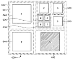
図6Bは、輝度サンプルグリッド上の32×32輝度サンプル配列を占有する、1セットの変換単位(TU)を含んで符号化単位(CU)602を占有する、32×32符号化単位(CU)の輝度チャネルに関して、図6Aの例示的な変換ツリーに対応する、例示的な変換ツリー630を図示する。図7は、例示的な変換ツリー630を表現するデータ構造700を図示する。図6Bにおいて、1〜10と番号付けられたボックスは、(いくつかの変換単位(TU)640によって例示された)領域632内に存在する変換単位を示し、各ボックスは、さらに細分割された(破線の境界線を有するボックスによって示された)領域内に含まれる。
FIG. 6B shows a 32 × 32 coding unit (CU) that occupies a coding unit (CU) 602 including a set of transform units (TU) that occupies a 32 × 32 luminance sample array on the luminance sample grid. FIG. 6B illustrates an
図6Bにおいて、1および9と番号付けられたボックスは、輝度チャネルに対する16×16変換を含み、2、3および8と番号付けられたボックスは、輝度チャネルに対する8×8変換を含む、4〜7と番号付けられたボックスは、輝度チャネルに対する4×4変換を含む。これらのボックスの各々に対応する領域(破線のボックス)は、変換の存在を示すために符号化ブロックフラグ値1を有する。 In FIG. 6B, the boxes numbered 1 and 9 include 16 × 16 transforms for the luminance channel, and the boxes numbered 2, 3, and 8 include 8 × 8 transforms for the luminance channel. The box numbered 7 contains a 4x4 transform for the luminance channel. The region corresponding to each of these boxes (dashed box) has a coded block flag value of 1 to indicate the presence of a transform.
各色チャネルに対する変換の有無は、以下に論じられるように、ビットストリームの各々の符号化/復号化に用いられるが、ビットストリームにおいては送信される必要はない、個別の符号化ブロックフラグ値によって指定される。結果的に、エントロピーデコーダ420から出力される残差係数配列450の数は、符号化ブロックフラグ値に依存する。どの色チャネル内にも有意係数がない場合、エントロピーデコーダ420から出力される残差係数配列450の数は、ゼロである。
The presence or absence of conversion for each color channel is specified by a separate encoded block flag value that is used to encode / decode each of the bitstreams, but need not be transmitted in the bitstream, as discussed below. Is done. As a result, the number of residual
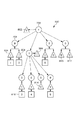
図7において、円は、対応する円の内部に示される分割変換フラグ値とともに分割変換フラグ値を表現する。図7において、三角形は、対応する三角形の内部に示される符号化ブロックフラグ値とともに符号化ブロックフラグ値を表現する。正方形は、図6Bにある変換番号に一致するように番号付けされた各変換とともに変換単位を表現する。 In FIG. 7, a circle expresses a division conversion flag value together with a division conversion flag value indicated inside the corresponding circle. In FIG. 7, a triangle represents an encoded block flag value together with an encoded block flag value shown inside the corresponding triangle. The square represents a conversion unit with each conversion numbered to match the conversion number in FIG. 6B.
例示的な変換ツリー630の最上部の階層レベルは、32×32符号化単位(CU)を占有する領域632を含んでいる。分割変換フラグ値702は、領域632が4つの16×16領域(例えば領域634)に細分割されることを示し、したがって例示的な変換ツリー630の「非リーフ」ノードを定義する。各16×16領域に関しては、分割変換フラグ値704などのさらなる分割変換フラグ値は、それぞれの16×16領域が4つの8×8領域にさらに細分割されるべきであることを示す。例えば、ゼロである分割変換フラグ値704によって示されるように、領域634はさらに細分割されず、したがって例示的な変換ツリー630の「リーフ」ノードを定義する。対照的に、1である分割変換フラグ値712によって示されるように、領域638は、領域636などの4つの4×4領域にさらに細分割される。変換ツリー630内に存在する再帰的な分割構造は、符号化ツリーブロック(CTB)内にある四分木分割に類似する。輝度チャネルに関しては、四分木の「リーフ」ノードにおいて、変換単位(TU)内の変換の有無が符号化ブロックフラグ値によって信号伝達され、例えば、1である符号化ブロックフラグ値708は、領域634内の変換710の有無を示す。
The top hierarchical level of the
変換が各領域内の残差データを表現するために用いられてもよいので、輝度チャネルに対して4×4輝度サンプルなど、領域がサポートされた最小変換サイズより小さくなることを許可しない。その上、利用可能な最大変換サイズより大きな領域に関しては、1である分割変換フラグ値が暗示される。例えば、64×64符号化単位のトップレベルを有する変換ツリーに関しては、サポートされた最大変換サイズが32×32輝度サンプルである場合、4つの32×32領域への自動細分割(すなわち:符号化ビットストリーム312内で信号伝達されない)が発生する。 Since a transform may be used to represent the residual data in each region, it does not allow the region to be smaller than the supported minimum transform size, such as 4 × 4 luminance samples for the luminance channel. In addition, for regions larger than the maximum conversion size that can be used, a division conversion flag value of 1 is implied. For example, for a transform tree with a top level of 64 × 64 coding units, if the maximum supported transform size is 32 × 32 luminance samples, automatic subdivision into four 32 × 32 regions (ie: coding) Is not signaled in the bitstream 312).
右下の16×16領域642は、輝度チャネルに対する変換がない変換単位(TU)(10と番号付けされ、網掛けされている)を含んでおり、そのため、対応するゼロである符号化ブロックフラグ値716を有する。
The lower right 16 × 16
図6Cおよび図8は、4:2:2色差フォーマットに構成され、輝度チャネルに対する変換ツリー630に対応し且つデータ構造800によって表現された色差チャネルに対する1セットの変換を含む、色差チャネルに対する、図6Aの例示的な変換ツリーに対応する例示的な変換ツリー630を図示する。変換ツリー階層が輝度チャネルと色差チャネルとの間の図6Aの構造によって共通するので、分割変換フラグ値は、データ構造700と800との間で共有される。データ構造700とは対照的に、データ構造800は、1である各変換分割フラグ値を有する符号化ブロックフラグ値を含む(すなわち変換ツリーの非リーフノード上に)。例えば、1である符号化ブロックフラグ値802は、変換分割フラグ702に関連づけられる。変換ツリーの非リーフノード上の符号化ブロックフラグ値がゼロである場合、子ノード上の符号化ブロックフラグ値は、ゼロとして暗示される(および、対応する符号化ブロックフラグは、符号化ビットストリーム312内で符号化されない)。非リーフ領域における符号化ブロックフラグ値は、たとえ大幅な残差係数が輝度チャネル内にあり得るとしても、大幅な残差係数が子領域のどれにもなければ、各色差チャネルに対する変換ツリーの下位レベルでの符号化ブロックフラグの符号化を終了することを可能にする。大部分の情報が輝度チャネル内にあるので、これは典型的な取得されたフレームデータに共通の状態である。
FIGS. 6C and 8 are diagrams for a chrominance channel configured in a 4: 2: 2 chrominance format and corresponding to the
ビデオエンコーダ114およびビデオデコーダ134が4:4:4色差フォーマット用に構成される場合、変換単位(TU)サイズの所定のセットの1つでないサイズの任意の変換単位(TU)の各色差チャネルの色差領域は、所定の変換単位(TU)の輝度領域と同一の寸法を有する(すなわち、暗黙的分割が行なわない場合)。ビデオエンコーダ114およびビデオデコーダ134が4:4:4色差フォーマットに構成される場合、変換単位(TU)サイズの所定のセットの1つであるサイズの任意の変換単位(TU)の各色差チャネルの色差領域は、所定の変換単位(TU)の輝度領域よりも小さな寸法を有する(すなわち、暗黙的分割が行なれる場合)。
If
4:2:2色差フォーマットが使用されている場合、これは、各色差チャネルに対して図6Cの色差サンプルの16×32領域662を含み、したがって、色差サンプルグリッド上の16×32領域を占有する、符号化単位(CU)602をもたらす。図6Cは、(図5Bとは対照的に)水平および垂直に等間隔に配置された各色差サンプルとともに、色差サンプルの配列として描画された、色差サンプルグリッド上の領域を図示する。4:2:2色差フォーマットの使用に起因して、図6Cの各色差領域は、図6Bの対応する輝度領域に対して水平に圧縮されたように見える。1である分割変換フラグ値702は、符号化単位(CU)602に対応する、16×32領域662を、8×16領域664などの4つの8×16領域に分割する。8×16領域664は、非正方形形状を有し、また、4×8領域670などの図6Cに図示された他の非正方形領域のサイズより大きい。各8×16領域に関しては、分割変換フラグ値704などの分割変換フラグ値は、輝度サンプル配列に対する変換ツリー630内にある四分木分割に類似した方式で、対応する8×16領域が4つのより小さな4×8領域にさらに細分割されるべきか否かを示す。右上の8×16領域672は、4つの4×8領域にさらに細分割される。1である符号化ブロックフラグ値804は、4つの4×8領域の各々が大幅な残差係数を含むかもしれないことを示す。各4×8領域に対する符号化ブロックフラグは、したがって、対応する領域に対する変換の有無を示すように要求される。これらの4つの4×8領域のうち、(網掛けされた)左下の4×8領域674は、変換単位(TU)を含むが、変換を含んでおらず、そのため、ゼロである符号化ブロックフラグ値814を有する。残りの4×8領域(領域670)は、各々、変換を有し、そのため、対応する1である符号化ブロックフラグ値を有する。左上の8×16領域は、2つの等しいサイズの8×8領域に細分割される。四分木細分割とは対照的に、対応する分割変換フラグは、符号化ビットストリーム312内にない。
If a 4: 2: 2 chrominance format is used, this includes the 16 × 32
符号化ビットストリーム312内にある信号伝達を行わずに、複数の領域(その各々は変換を有してもよい)への、変換単位(TU)の色差チャネルなどのチャネルの領域の分割は、「暗黙的分割」と呼ばれる。暗黙的分割は、このケース(8×16)のための非正方形変換をサポートするハードウェアを導入する必要を省く。その代わりに、第1の8×8変換666などの変換が用いられる。暗黙的分割から起因する領域の各々にとって、ゼロ残差情報をすべて含むことが可能であるので、暗黙的分割から起因する各領域内の変換の有無を指定することが必要である。従って、個別の符号化ブロックフラグ値は、暗黙的分割から起因する各領域に必要である。この場合、符号化ブロックフラグ値806および808は、第1の8×8変換666および第2の8×8変換668にそれぞれ対応する。暗黙的分割が行なわない変換単位(TU)に関しては、各色差チャネルに対する符号化ブロックフラグ値は、色差チャネルに対する変換単位(TU)によって占有された領域に対する変換の有無を指定する。暗黙的分割を行なう場合、個別の符号化ブロックフラグ値(図8には図示せず)は、結果として生じる領域の各々に対して必要であるが、しかしながら、実施態様は、全体の変換単位(TU)に帰着可能な符号化ブロックフラグ値を保持してもよい。すべてのケースのうちの「1つ」として個別の符号化ブロックフラグ値を暗示することができるかもしれないし、または、分割から起因する各領域の符号化ブロックフラグ値に対する論理的「OR」動作を実行することによって、個別の符号化ブロックフラグ値を決定することができるかもしれない。個別の符号化ブロックフラグ値が分割に起因する各領域の符号化ブロックフラグ値から決定される場合、個別の符号化ブロックフラグ値は、エントロピーエンコーダ324によって符号化ビットストリーム312内で符号化され、付加的な符号化ブロックフラグ(図9には図示せず)としてエントロピーデコーダ420によって符号化ビットストリーム312から復号化されてもよい。このようなケースにおいて、個別の符号化ブロックフラグ値がゼロである場合、分割から各領域の符号化ブロックフラグ値はゼロであると推論されてもよく、個別の符号化ブロックフラグ値が1である場合、分割から各々の領域に対する符号化ブロックフラグは、エントロピーエンコーダ324によって符号化ビットストリーム312内で符号化され、エントロピーデコーダ420によって符号化ビットストリーム312から復号化される。
Division of a channel region, such as a color difference channel of a transform unit (TU), into multiple regions (each of which may have a transform) without signaling within the encoded
16×32領域662の左下の8×16領域680は、8×8変換が上部の8×8暗示領域682内にあるが、8×8変換が下の8×8暗示領域684内にない暗黙的分割を図示する。右下の(網掛けされた)8×16配列676は、変換単位(TU)を含むが、暗黙的分割から起因する一方の正方形の8×8領域内の変換を含まず、そのため、ゼロである符号化ブロックフラグ値810、812を有する。
The lower left 8 × 16
2つの色差チャネルの有無は、各色差チャネルに対する変換の有無を指定するために用いられる個別の符号化ブロックフラグ値により、図6Cに表現された構造の複製をもたらす。この実施態様において、分割は、サイズ4×8以外の色差に対する領域サイズに対して推測され、結果として、(領域670内に含まれる)4×8変換816などの4×8の長方形変換を用いて他のケース(例えば8×8、16×16)における既存の正方形変換の再使用を可能にする。従って、8×16および16×32などの1セットの所定の領域サイズは、2つの領域への分割のために存在すると言ってもよく、したがって、(サイズ8×8および16×16の)2つの変換を用いることができる。また、推測分割が発生する領域サイズの所定のセットの個別の定義が可能であり、既存の正方形変換および長方形変換の個別の組み合わせが用いられることを可能にすることになる。また、分割を常に推測することはある実施態様にとって可能であり、その場合には、長方形変換は、色差4:2:2色チャネルに対して導入されない。このようなケースにおいて、推測分割が発生する領域サイズの所定のセットは、あらゆる色差領域サイズ(例えば、4:2:2色差フォーマットに対する4×8、8×16、および16×32、または4:4:4色差フォーマットに対する4×4、8×8、16×16、および32×32)を含んでいる。
4:2:0色差フォーマットが使用中である場合、推測分割は、変換単位(TU)内のいずれの色差領域に対しても行なわれないので、各色差チャネルに対する最大変換数は、常に1である(各色差チャネルに対する符号化ブロックフラグ値は、色差変換が発生するか否かをコントロールする)。
The presence or absence of two chrominance channels results in a copy of the structure depicted in FIG. 6C, with the individual coded block flag values used to specify the presence or absence of conversion for each chrominance channel. In this embodiment, the partitioning is inferred for region sizes for color differences other than
When the 4: 2: 0 color difference format is in use, the speculative division is not performed for any color difference region in the conversion unit (TU), so the maximum number of conversions for each color difference channel is always 1. Yes (the coding block flag value for each color difference channel controls whether color difference conversion occurs).
ビデオエンコーダ114およびビデオデコーダ134は、輝度と色差チャネルとの間の差分と無関係に記載され、色差フォーマットから起因する、異なるサンプルグリッドは、モジュール内の差分の必要性を要する。実際的な実施態様は、輝度チャネルおよび色差チャネルに対する個別の「処理経路」を有してもよい。このような実施態様は、したがって、輝度サンプルおよび色差サンプルの処理を分離してもよい。符号化ビットストリーム312が輝度チャネルおよび色差チャネルの両方に対して単一のビットストリームであるので、エントロピーエンコーダ324およびエントロピーデコーダ420は分離されない。その上、フレームバッファ332、432などの単一のフレームバッファは、輝度サンプルおよび色差サンプルを保持しており、したがって分離されない。但し、モジュール322〜330および334〜340、モジュール422〜430および434は、実施態様が分離された輝度処理および色差処理を有し、輝度および色差に対して個別のロジックを有することを可能にして、それにより、「輝度処理経路」および「色差処理経路」を生成してもよい。
ある実施態様は、2つの16×16領域への変換単位(TU)の色差チャネルの16×32領域に対する分割を推測してもよいが、8×16および4×8のケースに対する分割を推測しなくてもよい。このような実施態様は、当該技術分野において確立された4、8または16ポイントの変換ロジックに頼ることができる代わりに、色差処理経路に対して32ポイントの変換ロジックを導入する必要性を回避する。 Some implementations may infer the division for the 16 × 32 region of the color difference channel of the transform unit (TU) into two 16 × 16 regions, but infer the division for the 8 × 16 and 4 × 8 cases. It does not have to be. Such an implementation avoids the need to introduce 32 point conversion logic for the chrominance processing path instead of relying on 4, 8 or 16 point conversion logic established in the art. .
図9Aおよび図9Bは、変換ツリーの階層レベルを符号化するか、さもなければ表現するために用いることができる構文構造を図示する。変換ツリーの非リーフノードにおいて、変換ツリーに対応する符号化ビットストリーム312の一部にある構文要素を定義するために、構文構造900は、データ構造700、800などのデータ構造によって再帰的に拡大される。変換ツリーのリーフノード(変換ツリー内で細分割が行なわれない)において、構文構造930は、符号化ビットストリーム312の一部にある構文要素を定義する。通常は、付加データ構造は、アルファチャネルまたは深度マップを符号化するためなどに可能であるが、輝度のための1つのデータ構造および色差のための2つのデータ構造がある。または、少数のデータ構造は、単一のデータ構造が色差チャネルによって共有され、符号化ブロックフラグ値が色差チャネルの間で共有されることができるケースなどで利用されてもよい。変換ツリーの非リーフノード構文構造902は、変換ツリー630などの変換ツリーの1つの階層レベルの符号化を定義する。分割変換フラグ910は、分割変換フラグ値702などの、1である分割変換フラグ値を符号化する。この値は、変換ツリー非リーフノード構文構造902が変換ツリー非リーフノード構文構造902または変換ツリーリーフノード構文構造932の付加的な実例を含む低階層レベル、または「子ノード」を含むことを示す。符号化ブロックフラグ912は、「U」色差チャネルに対して1つの符号化ブロックフラグ値802を符号化し、符号化ブロックフラグ914は、「V」色差チャネルに対するさらなる符号化ブロックフラグ値を符号化する。変換ツリー非リーフノード構文構造902が変換ツリー階層のトップレベルを定義しているのであれば、符号化ブロックフラグ912、914が存在する。変換ツリー非リーフノード構文構造902が変換ツリー階層のトップレベルを定義していないのであれば、符号化ブロックフラグ912、914は、変換ツリー階層の親レベル内に対応する符号化ブロックフラグが存在して一価であれば、単に存在するだけである。(最上部の階層レベルに比べて)より低い階層レベルが変換ツリー630内に存在するとき、四分木細分割は行なわれる。この細分割は、変換ツリー非リーフノード構文構造902内に含まれる4つの変換ツリー構文構造916、918、920、922をもたらす。
9A and 9B illustrate a syntax structure that can be used to encode or otherwise represent the hierarchical levels of the transformation tree. In order to define syntax elements that are part of the encoded
構文構造930は、変換ツリーリーフノード932のリーフノードの符号化を定義する(すなわち、それ以上細分割が行なわない場合)。分割変換フラグ940は、分割変換フラグ値704などの0である分割変換フラグ値を符号化する。
The
対応する領域が最小サイズより大きい場合、分割変換フラグは、単に符号化される。例えば、領域636は、(サポートされた最小輝度変換サイズに対応する)4×4輝度サンプルの領域に対する容認できる最小サイズを有する。従って、変換分割フラグ値714は、ゼロとして推測され、分割変換フラグは、対応する変換ツリー構文構造に対して符号化されない。
If the corresponding region is larger than the minimum size, the split conversion flag is simply encoded. For example,
領域636に関しては、色差残差サンプルは、4×8色差変換を用いて変換され、従って、推測された変換分割は存在しない。符号化ブロックフラグ942および符号化ブロックフラグ946などの符号化ブロックフラグは、色差チャネルの各々に対する変換の有無を信号伝達するために存在してもよい。符号化ブロックフラグ950は、輝度チャネルに対する変換の有無を信号伝達する。輝度チャネルおよび色差チャネルのための残差係数(もし存在すれば)は、変換単位(TU)構文構造952内に存在する。符号化ブロックフラグ950の値が1であるならば、輝度残差ブロック954は、符号化ビットストリーム312内にある。各色差チャネルに対する符号化ブロックフラグの値が1であるならば、対応する色差残差ブロック956、960は、符号化ビットストリーム312内に存在する。
For
領域664に関しては、色差残差サンプルが2つの8×8色差変換を用いて変換され、従って、推測された変換分割は存在する。符号化ブロックフラグ942、946は、もし存在すれば、第1の8×8変換666の各色差チャネルに対して8×8変換の有無を信号伝達する。符号化ブロックフラグ944、符号化ブロックフラグ948は、もし存在すれば、第2の8×8変換668の各色差チャネルに対して8×8変換の有無を信号伝達する。符号化ブロックフラグ944の値が1であるならば、色差残差ブロック958は、符号化ビットストリーム312内に存在する。符号化ブロックフラグ948の値が1であるならば、色差残差ブロック962は、符号化ビットストリーム312内に存在する。
図9Bに図示されるような構文構造930は、推測された変換分割に隣接して符号化された各色差チャネルの第1および第2の変換を示す。隣接する各色差チャネルに対して構文要素を符号化するか、または他の構文要素とともに散在した各色差チャネルに対して構文要素を符号化する他の配列が、または用いられてもよい。
For
The
図9Cおよび図9Dは、変換ツリーの階層レベルを符号化するか、さもなければ表現するために用いることができる、代替的な構文構造9100を図示する。変換ツリーの非リーフノードにおいて、変換ツリーに対応する符号化ビットストリーム312の一部内にある構文要素を定義するために、代替的な構文構造9100は、データ構造700、800などのデータ構造に従って再帰的に拡大される。代替的な構文構造9100のインスタンスは、各変換単位(TU)を含む、リーフノードを含む変換ツリー内の各々のノードごとに存在する。各色差チャネルに対する変換単位(TU)を細分化するために「推測分割」が発生する場合、構文構造9130は、符号化ビットストリーム312の一部内にある構文要素を定義する。通常は、付加データ構造は、アルファチャネルまたは深度マップを符号化するためなどに可能であるが、輝度のための1つのデータ構造および色差のための2つのデータ構造がある。または、少数のデータ構造は、単一のデータ構造が色差チャネルによって共有され、符号化ブロックフラグ値が色差チャネルの間で共有されることができるケースなどで利用されてもよい。変換ツリー構文構造9102は、変換ツリー630などの変換ツリーの1つの階層レベルの符号化を定義する。
9C and 9D illustrate an
変換ツリー630などの変換ツリーの非リーフノードにおける変換ツリー構文構造9102のインスタンスに関しては、分割変換フラグ9110は、分割変換フラグ値702などの1である分割変換フラグ値を符号化する。この値は、変換ツリー構文構造9102のインスタンスが変換ツリー構文構造9102または「子ノード」の付加的な実例を含む、低い階層レベルを含むことを示す。符号化ブロックフラグ9112は、符号化ブロックフラグ912の記述によって符号化ブロックフラグ値を符号化する。符号化ブロックフラグ9114は、符号化ブロックフラグ914の記述によって符号化ブロックフラグ値を符号化する。(最上部の階層レベルに比べて)より低い階層レベルが変換ツリー630内に存在するとき、四分木細分割は行なわれる。この細分割は、変換ツリーノード構文構造9102内に含まれている、4つの変換ツリー構文構造9116、9118、9120、9122をもたらす。変換ツリー構文構造9116、9118、9120、9122の各々は、変換ツリー構文構造9102の別のインスタンスである。符号化ブロックフラグ9124および輝度変換単位部分9126は、変換ツリー構文構造9102から存在しないことになる。
For an instance of the conversion
実施態様は、また、変換ツリー構文構造9102を符号化ブロックフラグ9124および輝度変換単位部分9126(もし存在すれば)が、符号化ブロックフラグ9114と変換ツリー構文構造9116との間などの、変換ツリー構文構造9102内に初期に配置されるように配置してもよい。
Embodiments also include a transform
変換ツリー630などの変換ツリーのリーフノードにおける変換ツリー構文構造9102のインスタンスに関しては、分割変換フラグ9110は、分割変換フラグ値704などのゼロである分割変換フラグ値を符号化する。変換ツリー構文構造9102のインスタンスは、したがって、変換ツリー930内の変換単位(TU)に対応する。変換単位(TU)は、符号化単位(CU)602などの変換単位(CU)および変換深度を含む符号化単位(CU)によって決定されたサイズを有する。符号化ブロックフラグ9112は、「U」色差チャネルに対する推測分割に起因するあらゆる色差領域が1である符号化ブロックフラグ値を有してもよいことを示すために、1である符号化ブロックフラグ値を符号化する。符号化ブロックフラグ9112がゼロの値を符号化するならば、「U」色差チャネルに対する推測分割に起因する各色差領域に対する符号化ブロックフラグ値は、ゼロとして推測された符号化ブロックフラグ値を有する。符号ブロックフラグ9112が1である値を符号化する場合でさえ、実施態様は、推測分割から起因する各色差領域に対してゼロである値を有する符号化ブロックフラグをさらに符号化してもよい。そのため、実施態様は、符号化ビットストリーム312から符号化ブロックフラグ9112を省略してもよいが、その代り、省略された符号化ブロックフラグ9112に対して1つの符号化ブロックフラグ値を常に推測する。符号化ブロックフラグ9114は、符号化ブロックフラグ9112と同様の方式で「V」色差チャネルに対してさらなる符号化ブロックフラグ値を符号化する。4つの色差領域への推測分割が発生するものに一致する変換単位(TU)サイズに関して(色差残差係数配列の最大数は4である)、4つの変換ツリー構文構造9116、9118、9120、9122は、変換ツリーノード構文構造9102内に含まれる。2つの色差領域への推測分割が発生するものに一致する変換単位(TU)サイズに関して(色差残差係数配列の最大数は2である)、変換ツリー構文構造9116、9118などの2つの変換ツリー構文構造は、変換ツリーノード構文構造9102内に含まれる。変換ツリー構文構造9116、9118、9120、9122の各々は、色差構文構造9132に対する変換ツリーのインスタンスである。符号化ブロックフラグ9124は、変換単位(TU)の輝度チャネルに対する変換の欠如の有無を指定する、符号化ブロックフラグ値708などの符号化ブロックフラグ値を符号化する。変換単位9126の輝度部分は、輝度残差構文要素9128として輝度残差係数配列を符号化する。
For an instance of the transformation
推測分割が行なわれる場合に各色差領域対して存在するのみの、色差構文構造9132に対する変換ツリーは、変換ツリー構文構造930の構文の縮小されたセットを含む。符号化ブロックフラグ9142は、色差領域の「U」色差チャネルに対する符号化ブロックフラグ値を符号化する。符号化ブロックフラグ9144は、色差領域の「V」色差チャネルに対する符号化ブロックフラグ値を符号化する。変換単位(TU)9146の色差部分は、変換単位(TU)構文構造952のサブセットを符号化する。符号化ブロックフラグ9142の値が1であるならば、変換単位(TU)9146の色差部分は、「U」色差チャネルに対する色差残差構文要素9150として色差残差係数配列を符号化する。符号化ブロックフラグ9144の値が1であるならば、変換単位(TU)9146の色差部分は、「V」色差チャネルに対する色差残差構文要素9152として色差残差係数配列を符号化する。
The transformation tree for the
図9Dに図示されるような構文構造9130は、隣接して符号化された第1および第2の符号化ブロックフラグに続く、推測された変換分割に対する各色差チャネルの第1および第2の色差残差係数配列を示す。各色差チャネルに隣接して符号化ブロックフラグおよび色差残差係数配列を符号化するなどの他の配列が、代わりに用いられてもよい。
推測された変換分割は、2つの8×8領域への8×16領域664分割により図示されるが、代替的な実施態様は、他の領域に対する分割を実行してもよい。例えば、いくつかの実施態様は、2つの16×16領域への16×32領域の分割を推測してもよい。このような実施態様は、色差処理経路内の32ポイントの1次元変換に対する必要性を有利に回避する。4:2:0色差フォーマットが適用される場合、32ポイントの1次元変換が色差処理経路には必要でないので、32ポイントの1次元変換に対する要件は、色差処理経路から全体に取り除かれる。輝度および色差チャネルを分離する個別の処理回路を用いる実施態様は、したがって、色差処理回路の低実装コストを達成することができる。
The
Although the inferred transform partition is illustrated by an 8 × 16
各輝度サンプル位置に対する1つの色差サンプル位置があるところに、4:4:4色差フォーマットは存在する。従って、この形式により、色差チャネルおよび輝度チャネルに対する変換は、同一のサイズを有してもよい。輝度処理経路内の32×32の最大変換サイズにより、これは、分離された実装に対して色差処理経路内の32×32変換を導入することを要するだろう。特定の実施態様は、色差処理経路内の現存の16×16変換の再使用を可能にする、4つの16×16領域に、32×32領域を分割するために各色差チャネルに対する分割を推測してもよい。32×32変換が4:4:4色差フォーマットに対して色差処理経路においてのみ用いられるので、4つの16×16領域への32×32領域を分割する各々の色差チャネルに対する分割の推測は、必要とされる処理回路を低減して、32×32変換が色差処理経路から取り除かれるのを可能にする。このような実施態様は、各色差チャネルに対する4つの符号化ブロックフラグ値、したがって、符号化ビットストリーム312内の各色差チャネルに対して構文構造930内で符号化された4つの符号化ブロックフラグまで、を必要とするだろう。
The 4: 4: 4 color difference format exists where there is one color difference sample position for each luminance sample position. Thus, with this format, the transforms for the chrominance channel and the luminance channel may have the same size. With a maximum transform size of 32x32 in the luminance processing path, this would require the introduction of a 32x32 transform in the chrominance processing path for a separate implementation. Certain implementations infer a partition for each chrominance channel to divide a 32 × 32 region into four 16 × 16 regions, which allows reuse of existing 16 × 16 transforms in the chrominance processing path. May be. Since the 32x32 transform is used only in the chrominance processing path for the 4: 4: 4 chrominance format, an inference of division for each chrominance channel that divides the 32x32 region into four 16x16 regions is necessary Reducing the processing circuitry taken to allow 32 × 32 conversions to be removed from the color difference processing path. Such an implementation can have up to four encoded block flag values for each chrominance channel, and thus four encoded block flags encoded in the
4:2:2色差フォーマットをサポートする実施態様は、また、各色差チャネルが4つの8×16領域に32×16領域を分岐するために分割を推測してもよい。このような実施態様は、各色差チャネルに対する4つの符号化ブロックフラグ値を要し、したがって、符号化ビットストリーム312内の各色差チャネルに対して構文構造930内で符号化された4つの符号化ブロックフラグ、したがって「CU3」、「CU4」、「CV3」および「CV4」符号化ブロックフラグ(図9Bには図示せず)は、変換単位(TU)構文構造952内に導入されてもよい。このような実施態様は、色差処理経路への32ポイントの変換ロジックの導入を回避するとともに、8×16領域が細分割されない場合には、色差チャネルに対してサイズ8×16の変換を要する(輝度チャネル内の)サイズ16×16の変換単位(TU)に必要な8×16変換ロジックを再使用してもよい。
Implementations that support the 4: 2: 2 chrominance format may also infer splitting because each chrominance channel branches the 32 × 16 region into four 8 × 16 regions. Such an implementation requires four encoded block flag values for each chrominance channel, and thus the four encodings encoded in
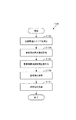
図10は、変換ツリー非リーフノード構文構造902および変換ツリーリーフノード構文構造932の符号化によって、変換単位(TU)を符号化する方法1000を示す概略フロー図である。方法1000は、変換単位(TU)の色差チャネルを参照しながら説明するが、方法1000は、変換単位(TU)のあらゆる色差チャネルに適用されてもよい。変換ツリー非リーフノード構文構造902および変換ツリーリーフノード構文構造932が、変換ツリー内の1つのノードを記載するため、方法1000は、符号化ビットストリーム312への変換ツリーの1つのノードを符号化する。例えば、方法1000は、ハードウェアにおいて、またはプロセッサー205上で実行可能なソフトウェアによって、実施されてもよい。方法1000は、変換ツリーのトップレベルに対して最初に起動され、変換ツリーの子ノードを符号化するためにそれ自体(再帰的に)起動することができる。変換単位サイズを決定するステップ1002は、変換ツリーおよび変換単位(TU)の変換深度値を含む符号化単位(CU)サイズに従って変換ツリーにおける変換単位(TU)のサイズを決定する。方法1000が変換ツリーのトップレベルで起動される場合、変換深度値は、ゼロに設定される。さもなければ、変換深度値は、方法1000の親インスタンスによって提供される。分割変換フラグ値702などの分割変換フラグ値は、変換深度値が変換深度を可能にする最大値未満であれば、分割変換フラグ910として符号化ビットストリーム312内で符号化される。
FIG. 10 is a schematic flow diagram illustrating a
分割変換フラグ値が1である場合、変換ツリー階層の親ノードが、1である対応する符号化ブロックフラグ値を有する場合にのみ、色差符号化ブロックフラグ912、914は、各色差チャネルに対して符号化される。方法1000は、その後、変換ツリーの(変換ツリー構文構造916、918、920、922によって符号化ビットストリーム312の部分において表現された)各子ノードに対して方法1000の新規のインスタンスを起動する。子ノードに対して起動された方法1000の各インスタンスには、1インクリメントした現在の方法1000インスタンス変換深度値に等しい変換深度値が提供される。
If the split transform flag value is 1, the chrominance coded block flags 912 and 914 are for each chrominance channel only if the parent node of the transform tree hierarchy has a corresponding coded block flag value of 1. Encoded.
分割変換フラグ値がゼロである場合、順方向変換の最大数を識別するステップ1004は、符号化されている領域の各色差チャネルに対して変換最大数(n)を決定する。推測分割が行なわれない場合、この数nは1になる。4:2:2色差フォーマットが使用され、8×16領域664などの色差チャネルの長方形領域に接触し、領域サイズが所定の領域サイズ(例えば16×32、8×16など)のセットの1つである場合、推測分割は行なわれ、最大変換数は2になるだろう(さもなければ、変換数は1になる)。さもなければ(領域サイズが所定の領域サイズのセットの1つではない場合)最大変換数は1になる。例えば、4×8が所定の領域サイズのセットの1つでなければ、最大変換数は1になる。4:4:4色差フォーマットが使用され、接触した領域サイズが所定の領域サイズ(例えば32×32領域など)のセットの1つである場合、推測分割は行なわれ、最大変換数は4になる。さもなければ(領域サイズが所定の領域サイズのセットの1つではない場合)最大数は1になる。例えば、8×8が所定の領域サイズのセットの1つでなければ、最大変換数は1になる。所定の領域サイズのセットは8×16を含むが、他の所定の領域サイズのセットは、4:2:2色差フォーマットが使用中のある場合に16×32、または4:4:4色差フォーマットが使用中のある場合に32×32などの場合のみに可能である。
If the split conversion flag value is zero,
各々の色差チャネルに対して、親ノードが1つの符号化ブロックフラグ値を有する場合、nの各々に対して、符号化ブロックフラグは、符号化ビットストリーム312内で符号化される。例えば、変換数が2に等しい場合、符号化ブロックフラグ942、944は、分割によって推測された2つの領域の各々に対する変換の有無を示す。順方向変換を選択するステップ1006は、変換深度に順番に依存し、したがって、最大符号化単位内の変換単位の階層レベルに関係する、変換単位(TU)のサイズに基づいて、最大変換数の各々に対して、所定の順方向変換のセットから順方向変換を選択する。変換深度がゼロに等しい場合、変換単位(TU)サイズは、符号化単位(CU)サイズに等しい。変換深度の各インクリメントに対して、変換単位(TU)サイズは半分になる。32×32符号化単位(CU)のサイズ、ゼロである変換深度、および4:2:2色差フォーマットを用いることに関しては、変換単位(TU)サイズは、したがって32×32になり、色差に対する変換サイズは、したがって16×32になる。例えば、最大変換数が2で、色差に対する領域サイズが16×32である場合、16×16順方向変換は、推測分割に起因する色差に対して16×16領域の各々に対して選択される。
For each chrominance channel, if the parent node has one encoded block flag value, for each n, the encoded block flag is encoded in the encoded
順方向変換を適用するステップ1008は、1である符号化ブロックフラグ値を有する、対応する領域上で最大変換数の各々に対して順方向変換を実行する。色差残差サンプル配列を符号化するステップ1008は、一般的に、変換モジュール320によって実行される。これは、色差残差係数配列(周波数領域表現)への各色差残差サンプル配列(空間領域表現)の変換をもたらす。
色差残差係数配列を符号化するステップ1010は、1である符号化ブロックフラグ値を有する各色差チャネルの変換領域の最大数の各々に対して、色差残差係数配列を符号化ビットストリーム312に符号化する。所定の色差チャネルについて所定の変換単位に対して符号化された色差残差係数配列の数は、各変換の符号化ブロックフラグ値に依存し、したがって、ゼロから(多くても)最大変換数まで変化することになる。例えば、変換数が2であり、双方の色差チャネルがカウント値の各々に対して1である符号化ブロックフラグ値を有する場合、色差残差ブロック956、958、960、962は、符号化ビットストリーム312内で符号化される。所定の色差チャネルに関して各変換に対する符号化ブロックフラグ値がゼロであるならば、色差残差ブロックは、その色差チャネルに対する符号化ビットストリーム312内で符号化されない。色差残差係数配列を符号化するステップ1010は、一般的に、エントロピーエンコーダ324によって実行される。
図11は、変換ツリー非リーフノード構文構造902および変換ツリーリーフノード構文構造932の復号化によって、変換単位(TU)を復号化する方法1100を示す概略フロー図である。方法1100は、変換単位(TU)の色差チャネルを参照して説明するが、方法1100は、変換単位(TU)のあらゆる色差チャネルに適用されてもよい。変換ツリー非リーフノード構文構造902および変換ツリーリーフノード構文構造932が、変換ツリー内の1つのノードを記載するため、方法1100は、符号化ビットストリーム312から変換ツリーの1つのノードを復号化する。方法1100は、適切なハードウェア、または代わりに例えばプロセッサー205によって実行可能なソフトウェアにおいて、実行されてもよい。方法1100は、変換ツリーのトップレベルに対して最初に起動され、変換ツリーの子ノードを復号化するためにそれ自体(再帰的に)起動することができる。変換単位(TU)サイズを決定するステップ1102は、変換単位サイズを決定するステップ1002と同一の方式で変換単位(TU)サイズを決定する。変換単位サイズを決定するステップ1102は、変換ツリーおよび変換単位(TU)の変換深度値を含む符号化単位(CU)サイズに従って変換ツリーにおける変換単位(TU)のサイズを決定する。方法1100が変換ツリーのトップレベルで起動される場合、変換深度値は、ゼロに設定されるか、さもなければ、変換深度値は、方法1100の親インスタンスによって提供される。分割変換フラグ値702などの分割変換フラグ値は、変換深度値が変換深度を可能にする最大値未満であれば、分割変換フラグ910として符号化ビットストリーム312から復号化される。
The
FIG. 11 is a schematic flow diagram illustrating a
分割変換フラグ値が1である場合、変換ツリー階層の親ノードが、1である対応する符号化ブロックフラグ値を有する場合にのみ、色差符号化ブロックフラグ912、914は、各色差チャネルに対して復号化される。方法1100は、その後、変換ツリーの(変換ツリー構文構造916、918、920、922によって符号化ビットストリーム312の部分において表現された)各子ノードに対して方法1100の新規のインスタンスを起動する。子ノードに対して起動された方法1100の各インスタンスには、1インクリメントした現在の方法1100インスタンス変換深度値に等しい変換深度値が提供される。
If the split transform flag value is 1, the chrominance coded block flags 912 and 914 are for each chrominance channel only if the parent node of the transform tree hierarchy has a corresponding coded block flag value of 1. Decrypted.
分割変換フラグ値がゼロである場合、逆変換の最大数を識別するステップ1104は、順方向変換の最大数(n)を識別するステップ1004と同一の方式で、復号化されている領域の各色差チャネル内にある少なくとも1つの色差残差係数配列の各々に対して(最大)変換数(n)を決定する。推測分割が行なわれない場合、この数nは1になる。4:2:2色差フォーマットが使用されており、8×16領域664などの色差チャネルの長方形領域に接触し、領域サイズが所定の領域サイズ(例えば16×32、8×16など)のセットの1つである場合、推測分割は行なわれ、最大変換数は2なる(さもなければ、変換数は1になる)。さもなければ(領域サイズが所定の領域サイズのセットの1つではない場合)最大変換数は1になる。例えば、4×8が所定の領域サイズのセットの1つでなければ、最大変換数は1になる。4:4:4色差フォーマットが使用されており、接触した領域サイズが所定の領域サイズ(例えば32×32領域など)のセットの1つである場合、推測分割は行なわれ、最大変換数は4になる。さもなければ(領域サイズが所定の領域サイズのセットの1つではない場合)最大数は1になる。例えば、8×8が所定の領域サイズのセットの1つでなければ、最大変換数は1になる。所定の領域サイズのセットは8×16を含むが、他の所定の領域サイズのセットは、4:2:2色差フォーマットが使用されている場合は16×32、または4:4:4色差フォーマットが使用されている場合は32×32などの場合のみに可能である。各々の色差チャネルに対して、親ノードが符号化ブロックフラグ値1を有する場合、(n個)の変換各々に対して、符号化ブロックフラグは、符号化ビットストリーム312内で復号化される。例えば、最大変換数が2に等しい場合、符号化ブロックフラグ942、944は、分割によって推測された2つの領域の各々に対する変換の有無を示す。
If the division transform flag value is zero,
色差残差係数配列を復号化するステップ1106は、その後、符号化ブロックフラグ値1を有する符号化ビットストリーム312から各色差チャネルの最大変換数領域の各々に対して残差係数配列を復号化する。所定の色差チャネルについて所定の変換単位に対して復号化された色差残差係数配列の数は、各変換の符号化ブロックフラグ値に依存し、したがって、ゼロから(多くても)「変換数(n)」まで変化することになる。例えば、変換数が2であり、双方の色差チャネルがカウント値の各々に対して1である符号化ブロックフラグを有する場合、色差残差ブロック956、958、960、962は、符号化ビットストリーム312から復号化される。色差残差係数配列を復号化するステップ1106は、一般的に、1である符号化ブロックフラグ値を有する各色差残差係数配列についてエントロピーデコーダ420によって実行される。
The
逆変換を選択するステップ1108は、その後、各色差チャネルに対して1である符号化ブロックフラグ値を有する最大変換数の各々に対して、所定の逆変換のセットから逆変換を選択する。例えば、最大変換数が2であり、領域サイズが16×32であり、2つの変換の各々に対する符号化ブロックフラグ値が1である場合、16×16逆変換が、推測分割から起因する16×16領域の各々に対して選択される。
逆変換を適用するステップ1110は、符号化ブロックフラグ値1を有する、対応する領域上の最大変換数の各々に対して逆変換を実行する。これは、復号化されたビデオフレームを表現する色差残差サンプル配列(空間領域表現)への各色差残差係数配列(周波数領域表現)の変換をもたらす。逆変換を適用するステップ1110は、一般的に、逆スケール/変換モジュール422によって実行される。
図12Aは、対角スキャンパターン1201を示し、図12Bは、水平スキャンパターン1202を示し、図12Cは、垂直走査パターン1203を示しており、各々は4×8変換単位1200に対するスキャンパターンを示す。図示されたスキャンパターンを用いて4×8変換単位1200をスキャンするそれらの実施態様は、残差係数が「サブブロック」として知られている4×4ブロックにおいてグループ化される特性を有する。そのため、符号化ビットストリーム312内にある「係数グループ」フラグは、各サブブロックに対して、少なくとも1つの有意な(ゼロでない)残差係数の有無を示すために用いられてもよい。4×8変換に対する4×4サブブロックサイズの適用は、係数がサブブロックに常にグループ化される、他の変換サイズ中のスキャンパターンとの整合性を実現する。
12A shows a
特定の実施態様は、各サブブロック内の少なくとも1つのゼロでない残差係数の有無を信号伝達するために係数グループフラグを適用してもよい。有利なことに、これらのスキャンパターンは、すべての変換サイズに対してサブブロック処理を再使用することによって、残差係数を処理する制御ソフトウェアまたはデジタル回路の再使用を可能にする。用いられる特定のスキャンパターンは、配置された予測単位(PU)のイントラ予測方向などの基準に従って選択されてもよい。変換によりが4:2:2色差フォーマットサンプルグリッド上の色差サンプルを符号化する場合、各色差サンプルが、輝度サンプルの非正方形(2×1)配列にマッピングされるためイントラ予測モードの「方向」または角度に影響を与えるので、イントラ予測方向とスキャンパターンとの間の関連性が変更される。スキャニングは、変換単位(TU)の左上隅に配置された、DC係数にて終了する「逆」方向に示される。さらに、スキャニングは、変換単位(TU)の右下コーナーから開始するようにする必要はない。変換単位(TU)の左上領域内のゼロでない残差係数の優位性に起因して、スキャニングは、「最後の有意係数位置」から開始して、左上係数に達する方向で逆方向に進んでもよい。 Particular implementations may apply a coefficient group flag to signal the presence or absence of at least one non-zero residual coefficient in each sub-block. Advantageously, these scan patterns allow reuse of control software or digital circuitry that processes residual coefficients by reusing sub-block processing for all transform sizes. The particular scan pattern used may be selected according to criteria such as the intra prediction direction of the arranged prediction units (PU). When encoding chrominance samples on a 4: 2: 2 chrominance format sample grid by transformation, each chrominance sample is mapped to a non-square (2 × 1) array of luminance samples, so the “direction” of the intra prediction mode Or, since the angle is affected, the relationship between the intra prediction direction and the scan pattern is changed. Scanning is shown in the “reverse” direction ending with a DC coefficient, located in the upper left corner of the transform unit (TU). Furthermore, the scanning need not start from the lower right corner of the transform unit (TU). Due to the superiority of the non-zero residual coefficient in the upper left region of the transform unit (TU), the scanning may start in the reverse direction, starting from the “last significant coefficient position” and reaching the upper left coefficient. .
他の実施態様は、残差係数を符号化するために所定の領域に対して単一のスキャンを適用し、その後、これらの残差係数に対して1つ以上の変換を適用してもよい。この場合、1つの符号化ブロックフラグのみが領域に対して、従ってスキャンパターンによってカバーされるすべての変換に対して、用いられる。少なくとも1つの有意な残差係数がいずれかのスキャン内に存在する場合、符号化ブロックフラグは1に設定される。例えば、図12A〜図12Cの4×8スキャンパターンは、2つの4×4変換の残差係数を符号化するために適用されてもよい。残差係数の2つの4×4配列は、スキャンパターンに適している4×8配列を形成するために連結されてもよい。単一のスキャンが配列を通じて実行されるので、単一の「最後の有意係数」の位置は、スキャンパターンに対してビットストリーム内で符号化され、単一の符号化ブロックフラグ値は、配列にとって十分である。修正離散コサイン変換(DCT)のエネルギー圧縮性は、長方形の係数配列へのスキャンパターンの経路に沿って各正方形変換の係数を交互配置するなどの他のスキームに対する有利性を与える。これは、各4×4残差係数配列内の残差係数値の密度が、エントロピーデコーダ420による後続の復号化に対して、高圧縮効率がエントロピーエンコーダ324によって生成されることを可能にする、組み合わされた4×8配列とほぼ等しくなるという有利性を与える。
Other embodiments may apply a single scan to a given region to encode the residual coefficients, and then apply one or more transforms to these residual coefficients. . In this case, only one coding block flag is used for the region and thus for all transforms covered by the scan pattern. The encoded block flag is set to 1 if at least one significant residual coefficient is present in any scan. For example, the 4 × 8 scan pattern of FIGS. 12A-12C may be applied to encode the residual coefficients of two 4 × 4 transforms. Two 4 × 4 arrays of residual coefficients may be concatenated to form a 4 × 8 array suitable for the scan pattern. Since a single scan is performed through the array, a single “last significant coefficient” position is encoded in the bitstream for the scan pattern, and a single encoded block flag value is assigned to the array. It is enough. The energy compressibility of the modified discrete cosine transform (DCT) provides an advantage over other schemes, such as interleaving the coefficients of each square transform along the path of the scan pattern to a rectangular coefficient array. This allows the density of residual coefficient values in each 4 × 4 residual coefficient array to allow a high compression efficiency to be generated by entropy encoder 324 for subsequent decoding by
色差の色チャネルを符号化するある実施態様は、4:2:0色差サンプルグリッドに対応する色差サンプル位置で残差サンプルを符号化する第1の変換と、4:2:0色差サンプルグリッドに対して、4:2:2色差サンプルグリッド内に導入された付加的な色差サンプル位置で残差サンプルを符号化する第2の変換とを用いてもよい。このような実施態様は、第2の変換の出力が第1の変換にたいして、第2の変換に対する残差サンプルを生成するために残差サンプルに加えられる(さもなければ組み合わされる)、アダマール変換などの、第2の変換に対して単純化された変換を有利に用いてもよい。有利には、ハール変換などの変換を実施する前処理段階は、4:2:0色差フォーマットに対する色差サンプルグリッドに、4:2:2色差フォーマットに対する色差サンプルグリッドをサンプリングするために用いられてもよい。このような構成はサイド情報として前処理段階から付加的な残差係数を伝送しなければならない。このような残差は、前処理変換が最大符号化単位(LCU)レベルで適用されるケースにおいて各最大符号化単位(LCU)に適用される。 One embodiment of encoding the color channel of the chrominance includes a first transform that encodes the residual sample at a chrominance sample location corresponding to the 4: 2: 0 chrominance sample grid, and a 4: 2: 0 chrominance sample grid. In contrast, a second transform that encodes the residual sample with additional chrominance sample locations introduced into the 4: 2: 2 chrominance sample grid may be used. Such an embodiment is such that the output of the second transform is added (otherwise combined) to the residual sample to produce a residual sample for the second transform relative to the first transform, etc. A simplified transformation of the second transformation may be advantageously used. Advantageously, a pre-processing stage that performs a transformation, such as a Haar transform, may be used to sample the chrominance sample grid for the 4: 2: 0 chrominance format and the chrominance sample grid for the 4: 2: 2 chrominance format. Good. In such a configuration, an additional residual coefficient must be transmitted as side information from the preprocessing stage. Such a residual is applied to each maximum coding unit (LCU) in the case where the pre-processing transform is applied at the maximum coding unit (LCU) level.
所定の領域に対する複数の変換を有する実施態様は、全体領域をカバーする単一の組み合わされたスキャンまたは個別のスキャンのいずれかを各々の変換に対して用いてもよい。複数の変換に対するスキャニングが単一のスキャンに組み合わされた場合、1つの符号化ブロックフラグのみが、スキャンされる各領域に必要である。単一の組み合わされたスキャンを用いるそれら実施態様は、同様の分光特性を有する各変換から残差係数を配置するために、係数ごとに基づいて交互配置するなど、各変換の残差係数を交互配置することによって、残差係数の高圧縮を実現してもよい。 Embodiments having multiple transforms for a given region may use either a single combined scan or individual scans covering the entire region for each transform. If scanning for multiple transforms is combined into a single scan, only one encoded block flag is required for each region scanned. Those embodiments that use a single combined scan alternate the residual coefficients of each transform, such as interleaving on a per-coefficient basis to place residual coefficients from each transform with similar spectral characteristics. By arranging, high compression of the residual coefficient may be realized.
付録Aは、構文構造900および構文構造930に関連する開発中の高効率動画像符号化方式(HEVC)規格にありうる「テキスト」を図示する。付録Aにおけるtransform_tree()関数の各インスタンスは、図9Aおよび図9Cにおいて「TT」とラベルづけされた構文構造の一部として表現され、付録Aにおけるtransform_unit()関数の各インスタンスは、図9Aおよび図9Bにおいて「TU」とラベルづけされた構文構造の一部として表現される。付録A内に提示されるテキストは、構文構造900、930に対応するテキストの一例であり、他の例も可能である。構文構造900、930に対応するテキストは、ビデオエンコーダ114がビットストリームを符号化する方法1000を実行し、ビデオデコーダ134がビットストリームを復号化する方法1100を実行する、ということを暗に示す。
Appendix A illustrates “text” that may be in the developing High Efficiency Video Coding (HEVC) standard associated with
付録Bは、構文構造9100および構文構造9130に関連する開発中の高効率動画像符号化方式(HEVC)規格にありうる「テキスト」を図示する。付録Bにおけるtransform_tree()関数の各インスタンスは、図9Cおよび図9Dにおいて「TT」とラベルづけされた構文構造の一部として表現され、付録Aにおけるtransform_unit()関数の各インスタンスは、図9Cおよび図9Dにおいて「TU」とラベルづけされた構文構造の一部として表現される。付録B内に提示されるテキストは、構文構造9100、9130に一致するテキストの一例であり、他の例も可能である。構文構造9100、9130に対応するテキストは、ビデオエンコーダ114がビットストリームを符号化する方法1000を実行し、ビデオデコーダ134がビットストリームを復号化する方法1100を実行する、ということを暗に示す。
Appendix B illustrates “text” that may be in the developing High Efficiency Video Coding (HEVC) standard related to
付録Aおよび付録B内のテキストは、結果として実装され、それによって、4:4:4色差フォーマットに対して構成されたサイズ32×32の変換単位(TU)において接する32×32色差領域は、適用される(最大数の)4つの16×16色差変換をもたらし、4:2:2色差フォーマットに対して構成されたサイズ32×32の変換単位(TU)において接する16×32色差領域は、適用される(最大数の)2つの16×16色差変換をもたらす。付録Aおよび付録B内のテキストに起因する実装は、より小さなサイズの変換単位(TU)に適用されて4:2:2色差フォーマットに対して構成された場合、(最大の)1つの色差変換が適用される。例えば、8×16変換は、8×16色差領域に適用され、4×8変換は、4×8色差領域に対する適用される。 The text in Appendix A and Appendix B is implemented as a result, so that the 32 × 32 color difference region that touches in a size 32 × 32 transform unit (TU) configured for the 4: 4: 4 color difference format is The resulting 16 × 16 color difference transforms (maximum number) are applied, and the 16 × 32 color difference regions tangent in a size 32 × 32 transform unit (TU) configured for the 4: 2: 2 color difference format are This results in two (16) 16 color difference transformations (maximum number) applied. The implementation resulting from the text in Appendix A and Appendix B is applied to a smaller size conversion unit (TU) and configured for a 4: 2: 2 color difference format (maximum) one color difference conversion. Applies. For example, an 8 × 16 transform is applied to an 8 × 16 color difference region, and a 4 × 8 transform is applied to a 4 × 8 color difference region.
記載の構成は、コンピュータおよび情報処理産業に適用可能であり、特にビデオ信号などの信号の符号化および復号化のためのデジタル信号処理に適用可能である。
前述のものは、本発明のいくつかの実施形態のみを記載しており、変形および/または変更は、本発明の範囲および精神、例示的であり限定的でない実施形態から逸脱せずに行なうことができる。
The described arrangement is applicable to the computer and information processing industries, and in particular to digital signal processing for encoding and decoding signals such as video signals.
The foregoing describes only some embodiments of the invention, and variations and / or modifications may be made without departing from the scope and spirit of the invention, which are exemplary and not limiting. Can do.
(オーストラリアのみ)この明細書との関連において、単語「備える(comprising)」は、「主として但し必ずではなく単に含む(including )」または「有する(having)」または「含む(including)」ことを意味し、「だけから構成される(consisting only of)」ことは意味しない。「備える(comprise)」および「備える(comprises)」などの単語「備える」の多様性は、対応する多様の意味を有する。 (Australia only) In the context of this specification, the word “comprising” means “including, but not necessarily, simply” or “having” or “including”. However, it does not mean “consisting only of”. The diversity of the word “comprise”, such as “comprise” and “comprises”, has a corresponding variety of meanings.
[付録A]
transform_tree ()およびtransform_unit()は、ループ構成体を用いて推測された色差分割を実施する
7.3.11 変換ツリー構文

transform_tree () and transform_unit () perform color difference partitioning estimated using a loop construct. 7.3.11 Transformation Tree Syntax
7.3.12 変換単位構文
7.4.8.1 概略の符号化単位セマンティックス
変数TrafoCrCbHorCntおよびTrafoCrCbVertCntは、以下の通りに導き出される:
・log2TrafoSizeが5に等しく、split_transform_flagが0に等しい場合、TransformIdxMaxは、以下のように導き出される:
・chroma_format_idcが1に等しい場合、TrafoCrCbHorCntおよびTrafoCrCbVertCntは、1に等しい。
・chroma_format_idcが2に等しい場合、TrafoCrCbHorCntは、1に等しく、TrafoCrCbVertCntは、2に等しい。
・さもなければ、chroma_format_idcが3に等しい場合、TrafoCrCbHorCntおよびTrafoCrCbVertCntは、2に等しい。
・さもなければ、TrafoCrCbHorCntおよびTrafoCrCbVertCntは、1に等しい。
変数TrafoCrCbCntは、TrafoCrCbHorCnt×TrafoCrCbVertCntとして導き出される。
変数log2CrCbTrafoHorSizeおよびlog2CrCbTrafoVertSizeは、以下の通りに導き出される:
・chroma_format_idcが1に等しい場合、log2CrCbTrafoHorSizeおよびlog2CrCbTrafoVertSizeは、log2TrafoSize−1に等しい。
・さもなければ、chroma_format_idcが2に等しい場合、log2CrCbTrafoHorSizeは、log2TrafoSizeに等しく、log2CrCbTrafoVertSizeは、min(log2TrafoSize−1,4)に等しい。
・さもなければ、chroma_format_idcが3に等しい場合、log2CrCbTrafoHorSizeおよびlog2CrCbTrafoVertSizeは、min(log2TrafoSize,4)に等しい。
付録Aの終了
7.4.8.1 The approximate coding unit semantic variables TrafoCrCbHorCnt and TrafoCrCbVertCnt are derived as follows:
If log2TrafoSize is equal to 5 and split_transform_flag is equal to 0, then TransIdIdMax is derived as follows:
If chroma_format_idc is equal to 1, then TrafoCrCbHorCnt and TrafoCrCbVertCnt are equal to 1.
If chroma_format_idc is equal to 2, then TrafoCrCbHorCnt is equal to 1 and TrafoCrCbVertCnt is equal to 2.
Otherwise, if chroma_format_idc is equal to 3, then TrafoCrCbHorCnt and TrafoCrCbVertCnt are equal to 2.
Otherwise, TrafoCrCbHorCnt and TrafoCrCbVertCnt are equal to 1.
The variable TrafoCrCbCnt is derived as TrafoCrCbHorCnt × TrafoCrCbVertCnt.
The variables log2CrCbTrafoHorSize and log2CrCbTrafoVertSize are derived as follows:
If chroma_format_idc is equal to 1, log2CrCbTrafoHorSize and log2CrCbTrafoVertSize are equal to log2TrafoSize-1.
Otherwise, if chroma_format_idc is equal to 2, log2CrCbTrafoHorSize is equal to log2TrafoSize and log2CrCbTrafoVertSize is equal to min (log2TrafoSize-1,4).
Otherwise, if chroma_format_idc is equal to 3, log2CrCbTrafoHorSize and log2CrCbTrafoVertSize are equal to min (log2TrafoSize, 4).
End of Appendix A
[付録B]
transform_tree()を、推測分割から起因する各色差変換に対する色差チャネルのペアにつき一度起動する。
7.3.11 変換ツリー構文
transform_tree () is activated once for each pair of color difference channels for each color difference conversion resulting from the speculative partitioning.
7.3.11. Transformation tree syntax
7.3.12 変換単位構文
7.4.8.1 概略の符号化単位セマンティックス
変数TrafoCrCbHorCntおよびTrafoCrCbVertCntは、以下の通りに導き出される:
・log2TrafoSizeが5に等しく、split_transform_flagが0に等しい場合、TransformIdxMaxは、以下のように導き出される:
・chroma_format_idcが1に等しい場合、TrafoCrCbHorCntおよびTrafoCrCbVertCntは、1に等しい。
・chroma_format_idcが2等しい場合、TrafoCrCbHorCntは、1に等しく、TrafoCrCbVertCntは、2に等しい。
・他の場合には、chroma_format_idcが3に等しい場合、TrafoCrCbHorCntおよびTrafoCrCbVertCntは、2に等しい。
・他の場合には、TrafoCrCbHorCntおよびTrafoCrCbVertCntは、1に等しい。
変数TrafoCrCbCntは、TrafoCrCbHorCnt×TrafoCrCbVertCntとして導き出される。
付録Bの終了
7.4.8.1 The approximate coding unit semantic variables TrafoCrCbHorCnt and TrafoCrCbVertCnt are derived as follows:
If log2TrafoSize is equal to 5 and split_transform_flag is equal to 0, then TransIdIdMax is derived as follows:
If chroma_format_idc is equal to 1, then TrafoCrCbHorCnt and TrafoCrCbVertCnt are equal to 1.
If chroma_format_idc is equal to 2, then TrafoCrCbHorCnt is equal to 1 and TrafoCrCbVertCnt is equal to 2.
-Otherwise, if chroma_format_idc is equal to 3, then TrafoCrCbHorCnt and TrafoCrCbVertCnt are equal to 2.
In other cases, TrafoCrCbHorCnt and TrafoCrCbVertCnt are equal to 1.
The variable TrafoCrCbCnt is derived as TrafoCrCbHorCnt × TrafoCrCbVertCnt.
End of Appendix B
Claims (12)
符号化単位のサイズおよび前記符号化単位内の変換単位の階層レベルに従って、正方形ブロックで表される前記変換単位の変換サイズを決定するステップと、
各色差チャンネルにおいて、
前記ビデオビットストリームから、前記変換単位が有する2つの色差残差係数配列のそれぞれに対応する2つの符号化ブロックフラグ値を復号するステップと、
前記2つの符号化ブロックフラグ値のうちの対応する符号化ブロックフラグ値に従って、前記2つの色差残差係数配列の各々を前記ビデオビットストリームから復号するステップと、
前記決定された変換サイズに対応する正方形ブロックのための変換を、前記復号された色差残差係数配列の各々に対して適用することにより、色差残差サンプルを生成するステップと、
を備え、
前記2つの色差残差係数配列の各々を前記ビデオビットストリームから復号するステップにおいて、前記2つの色差残差係数配列の各々に対して同じスキャンパターンを適用することにより、正方形ブロックで表される前記決定された変換サイズの変換単位を生成することを特徴とする方法。 From the video bitstream , two chrominance residual coefficient arrays respectively associated with two chrominance channels included in a transform unit in a 4: 2: 2 format encoding unit are decoded, and the decoded chrominance residual is decoded. A method for converting a coefficient array from a frequency domain to a spatial domain color difference residual sample, comprising:
Determining a transform size of the transform unit represented by a square block according to the size of the coding unit and the hierarchical level of the transform unit within the coding unit;
In each color difference channel
Decoding two encoded block flag values corresponding to each of the two color difference residual coefficient arrays of the transform unit from the video bitstream;
Decoding each of the two chrominance residual coefficient arrays from the video bitstream according to a corresponding encoded block flag value of the two encoded block flag values;
Generating a chrominance residual sample by applying a transform for a square block corresponding to the determined transform size to each of the decoded chrominance residual coefficient arrays;
With
In the step of decoding each of the two chrominance residual coefficient arrays from the video bitstream, by applying the same scan pattern to each of the two chrominance residual coefficient arrays, wherein that you generate the determined transform units transform size.
各色差チャンネルにおいて、
前記符号化単位のサイズおよび前記符号化単位内の前記変換単位の階層レベルに従って決定されるサイズの正方形ブロックのための変換を、前記変換単位の2セットの色差残差サンプルの少なくとも1つに対して適用することにより、前記2つの周波数領域の色差残差係数配列を生成するステップと、
前記変換単位の2つの色差残差係数配列にそれぞれ対応する2つの符号化ブロックフラグ値および前記2つの色差残差係数配列を前記ビデオビットストリームに符号化するステップと、を備え、
前記2つの色差残差係数配列を生成するステップにおいて、前記変換によって生成される2セットの残差係数に対して同じスキャンパターンを適用することにより、前記2つの色差残差係数配列を生成することを特徴とする方法。 Two color difference residual coefficient arrays included in the conversion unit in the 4: 2: 2 format encoding unit in each of the two color difference channels by converting the color difference residual sample in the spatial domain to the frequency domain As a bitstream encoding method,
In each color difference channel
Transform for at least one of the two sets of color difference residual samples of the transform unit for a square block of a size determined according to the size of the coding unit and the hierarchical level of the transform unit within the coding unit; Generating a color difference residual coefficient array of the two frequency regions by applying
Encoding the two encoded block flag values respectively corresponding to the two color difference residual coefficient arrays of the transform unit and the two color difference residual coefficient arrays into the video bitstream;
In the step of generating the two color difference residual coefficients sequence by applying the same scan patterns for residual coefficients of the two sets that are generated by the conversion, that generates the two chrominance residual coefficients sequence A method characterized by that.
符号化単位のサイズおよび前記符号化単位内の変換単位の階層レベルに従って、正方形ブロックで表される前記変換単位の変換サイズを決定するステップと、
各色差チャンネルにおいて、
前記ビデオビットストリームから、前記変換単位が有する2つの色差残差係数配列のそれぞれに対応する2つの符号化ブロックフラグ値を復号する手段と、
前記2つの符号化ブロックフラグ値のうちの対応する符号化ブロックフラグ値に従って、前記2つの色差残差係数配列の各々を前記ビデオビットストリームから復号する手段と、
前記決定された変換サイズに対応する正方形ブロックのための変換を、前記復号された色差残差係数配列の各々に対して適用することにより、色差残差サンプルを生成する手段と、
を備え、
前記2つの色差残差係数配列の各々を前記ビデオビットストリームから復号する手段において、前記2つの色差残差係数配列の各々に対して同じスキャンパターンを適用することにより、正方形ブロックで表される前記決定された変換サイズの変換単位を生成することを特徴とする復号装置。 A plurality of decoded color difference residuals are decoded from the video bitstream by decoding two color difference residual coefficient arrays respectively associated with two color difference channels included in a conversion unit in a 4: 2: 2 format encoding unit. A decoding device for converting a coefficient array from a frequency domain to a spatial domain color difference residual sample,
Determining a transform size of the transform unit represented by a square block according to the size of the coding unit and the hierarchical level of the transform unit within the coding unit;
In each color difference channel
Means for decoding two encoded block flag values corresponding to each of the two color difference residual coefficient arrays of the transform unit from the video bitstream;
Means for decoding each of the two chrominance residual coefficient arrays from the video bitstream according to a corresponding encoded block flag value of the two encoded block flag values;
Means for generating a color difference residual sample by applying a transform for a square block corresponding to the determined transform size to each of the decoded color difference residual coefficient arrays;
Equipped with a,
In the means for decoding each of the two chrominance residual coefficient arrays from the video bitstream, by applying the same scan pattern to each of the two chrominance residual coefficient arrays, decoding apparatus characterized that you generate the determined transform units transform size.
各色差チャンネルにおいて、
前記符号化単位のサイズおよび前記符号化単位内の前記変換単位の階層レベルに従って決定されるサイズの正方形ブロックのための変換を、前記変換単位の2セットの色差残差サンプルの少なくとも1つに対して適用することにより、前記2つの周波数領域の色差残差係数配列を生成する手段と、
前記変換単位の2つの色差残差係数配列にそれぞれ対応する2つの符号化ブロックフラグ値および前記2つの色差残差係数配列を前記ビデオビットストリームに符号化する手段と、を備え、前記2つの色差残差係数配列を生成する手段において、前記変換によって生成される2セットの残差係数に対して同じスキャンパターンを適用することにより、前記2つの色差残差係数配列を生成することを特徴とする符号化装置。 Two color difference residual coefficient arrays included in the conversion unit in the 4: 2: 2 format encoding unit in each of the two color difference channels by converting the color difference residual sample in the spatial domain to the frequency domain An encoding device that encodes a bitstream as
In each color difference channel
Transform for at least one of the two sets of color difference residual samples of the transform unit for a square block of a size determined according to the size of the coding unit and the hierarchical level of the transform unit within the coding unit; Means for generating a color difference residual coefficient array of the two frequency regions,
Means for encoding the two encoded block flag values respectively corresponding to the two color difference residual coefficient arrays of the transform unit and the two color difference residual coefficient arrays into the video bitstream, the two color differences in means for generating a residual coefficient array, by applying the same scan patterns for residual coefficients of the two sets that are generated by the conversion, a feature that you generate said two color difference residual coefficients sequence Encoding device .
Applications Claiming Priority (2)
| Application Number | Priority Date | Filing Date | Title |
|---|---|---|---|
| AU2012232992 | 2012-09-28 | ||
| AU2012232992A AU2012232992A1 (en) | 2012-09-28 | 2012-09-28 | Method, apparatus and system for encoding and decoding the transform units of a coding unit |
Related Parent Applications (1)
| Application Number | Title | Priority Date | Filing Date |
|---|---|---|---|
| JP2015533379A Division JP6282278B2 (en) | 2012-09-28 | 2013-09-27 | Method, apparatus, and system for encoding and decoding transform unit of encoding unit |
Publications (2)
| Publication Number | Publication Date |
|---|---|
| JP2018101984A JP2018101984A (en) | 2018-06-28 |
| JP6567100B2 true JP6567100B2 (en) | 2019-08-28 |
Family
ID=50386719
Family Applications (3)
| Application Number | Title | Priority Date | Filing Date |
|---|---|---|---|
| JP2015533379A Active JP6282278B2 (en) | 2012-09-28 | 2013-09-27 | Method, apparatus, and system for encoding and decoding transform unit of encoding unit |
| JP2017248473A Pending JP2018085738A (en) | 2012-09-28 | 2017-12-25 | Method for encoding and decoding residual coefficients, method for encoding residual coefficients from residual samples, apparatus, program, and computer readable storage medium |
| JP2018009529A Active JP6567100B2 (en) | 2012-09-28 | 2018-01-24 | Method, apparatus, and system for encoding and decoding transform unit of encoding unit |
Family Applications Before (2)
| Application Number | Title | Priority Date | Filing Date |
|---|---|---|---|
| JP2015533379A Active JP6282278B2 (en) | 2012-09-28 | 2013-09-27 | Method, apparatus, and system for encoding and decoding transform unit of encoding unit |
| JP2017248473A Pending JP2018085738A (en) | 2012-09-28 | 2017-12-25 | Method for encoding and decoding residual coefficients, method for encoding residual coefficients from residual samples, apparatus, program, and computer readable storage medium |
Country Status (11)
| Country | Link |
|---|---|
| US (4) | US9854241B2 (en) |
| EP (2) | EP3684057B1 (en) |
| JP (3) | JP6282278B2 (en) |
| KR (5) | KR101911200B1 (en) |
| CN (5) | CN108683914B (en) |
| AU (4) | AU2012232992A1 (en) |
| BR (2) | BR112015006767B1 (en) |
| ES (1) | ES2788757T3 (en) |
| PL (1) | PL2901673T3 (en) |
| RU (3) | RU2642825C1 (en) |
| WO (1) | WO2014047693A1 (en) |
Families Citing this family (101)
| Publication number | Priority date | Publication date | Assignee | Title |
|---|---|---|---|---|
| US9609353B2 (en) * | 2010-12-14 | 2017-03-28 | M&K Holdings Inc. | Apparatus for encoding a moving picture |
| CN107105282B (en) * | 2010-12-14 | 2019-11-12 | M&K控股株式会社 | Equipment for decoding moving pictures |
| US9473789B2 (en) * | 2010-12-14 | 2016-10-18 | M&K Holdings Inc. | Apparatus for decoding a moving picture |
| WO2013109026A1 (en) * | 2012-01-18 | 2013-07-25 | 엘지전자 주식회사 | Method and device for entropy coding/decoding |
| US10616581B2 (en) | 2012-01-19 | 2020-04-07 | Huawei Technologies Co., Ltd. | Modified coding for a transform skipped block for CABAC in HEVC |
| US9654139B2 (en) | 2012-01-19 | 2017-05-16 | Huawei Technologies Co., Ltd. | High throughput binarization (HTB) method for CABAC in HEVC |
| US9860527B2 (en) | 2012-01-19 | 2018-01-02 | Huawei Technologies Co., Ltd. | High throughput residual coding for a transform skipped block for CABAC in HEVC |
| US20130188736A1 (en) | 2012-01-19 | 2013-07-25 | Sharp Laboratories Of America, Inc. | High throughput significance map processing for cabac in hevc |
| US9743116B2 (en) | 2012-01-19 | 2017-08-22 | Huawei Technologies Co., Ltd. | High throughput coding for CABAC in HEVC |
| CN108712652A (en) | 2012-06-29 | 2018-10-26 | 韩国电子通信研究院 | Method for video coding and computer-readable medium |
| AU2012232992A1 (en) | 2012-09-28 | 2014-04-17 | Canon Kabushiki Kaisha | Method, apparatus and system for encoding and decoding the transform units of a coding unit |
| US9332257B2 (en) * | 2012-10-01 | 2016-05-03 | Qualcomm Incorporated | Coded black flag coding for 4:2:2 sample format in video coding |
| JP6270861B2 (en) * | 2012-11-08 | 2018-01-31 | キヤノン株式会社 | Method, apparatus and system for encoding and decoding transform units of a coding unit |
| GB2512825A (en) * | 2013-04-05 | 2014-10-15 | British Broadcasting Corp | Transmitting and receiving a composite image |
| GB2512658B (en) * | 2013-04-05 | 2020-04-01 | British Broadcasting Corp | Transmitting and receiving a composite image |
| US9686561B2 (en) * | 2013-06-17 | 2017-06-20 | Qualcomm Incorporated | Inter-component filtering |
| WO2015056566A1 (en) * | 2013-10-15 | 2015-04-23 | ソニー株式会社 | Image processing device and method |
| JP6066945B2 (en) * | 2014-02-21 | 2017-01-25 | キヤノン株式会社 | Image decoding apparatus, image decoding method and program |
| AU2015228999B2 (en) * | 2014-03-14 | 2018-02-01 | Vid Scale, Inc. | Systems and methods for RGB video coding enhancement |
| WO2016054774A1 (en) * | 2014-10-08 | 2016-04-14 | Mediatek Singapore Pte. Ltd. | A method for the co-existence of color-space transform and cross-component prediction |
| WO2016206590A1 (en) * | 2015-06-23 | 2016-12-29 | Mediatek Singapore Pte. Ltd. | Method and apparatus for transform coefficient coding of non-square blocks |
| US11076153B2 (en) * | 2015-07-31 | 2021-07-27 | Stc.Unm | System and methods for joint and adaptive control of rate, quality, and computational complexity for video coding and video delivery |
| US10491922B2 (en) | 2015-09-29 | 2019-11-26 | Qualcomm Incorporated | Non-separable secondary transform for video coding |
| US10674146B2 (en) | 2015-09-30 | 2020-06-02 | Lg Electronics Inc. | Method and device for coding residual signal in video coding system |
| US10277896B2 (en) | 2016-01-22 | 2019-04-30 | Apple Inc. | Intra-frame prediction systems and methods |
| WO2017135759A1 (en) * | 2016-02-04 | 2017-08-10 | 삼성전자 주식회사 | Video decoding method and apparatus by chroma-multi-transform, and video encoding method and apparatus by chroma-multi-transform |
| EP3430808A4 (en) * | 2016-03-16 | 2020-01-15 | Mediatek Inc. | Method and apparatus of video data processing with restricted block size in video coding |
| CN108886613B (en) * | 2016-03-28 | 2022-04-19 | 株式会社Kt | Method and apparatus for processing video signal |
| CN116647680A (en) * | 2016-10-28 | 2023-08-25 | 韩国电子通信研究院 | Video encoding/decoding method and apparatus, and recording medium storing bit stream |
| CN116847069A (en) | 2016-11-25 | 2023-10-03 | 株式会社Kt | Method for encoding and decoding video |
| US10666937B2 (en) | 2016-12-21 | 2020-05-26 | Qualcomm Incorporated | Low-complexity sign prediction for video coding |
| EP3565249A4 (en) * | 2016-12-28 | 2019-12-18 | Sony Corporation | Image processing apparatus and method |
| WO2018174457A1 (en) * | 2017-03-22 | 2018-09-27 | 엘지전자(주) | Image processing method and device therefor |
| US10779007B2 (en) * | 2017-03-23 | 2020-09-15 | Mediatek Inc. | Transform coding of video data |
| JP6680260B2 (en) * | 2017-04-28 | 2020-04-15 | 株式会社Jvcケンウッド | IMAGE ENCODING DEVICE, IMAGE ENCODING METHOD, IMAGE ENCODING PROGRAM, IMAGE DECODING DEVICE, IMAGE DECODING METHOD, AND IMAGE DECODING PROGRAM |
| EP3451663A1 (en) * | 2017-08-31 | 2019-03-06 | Thomson Licensing | Pools of transforms for local selection of a set of transforms in video coding |
| US20190116374A1 (en) * | 2017-10-17 | 2019-04-18 | Qualcomm Incorporated | Coding motion information of video data using coding structure-based candidate list construction |
| US10368071B2 (en) * | 2017-11-03 | 2019-07-30 | Arm Limited | Encoding data arrays |
| CN115002459A (en) | 2018-01-05 | 2022-09-02 | Sk电信有限公司 | Video decoding apparatus, video encoding apparatus, and non-transitory computer readable medium |
| KR102524628B1 (en) | 2018-01-05 | 2023-04-21 | 에스케이텔레콤 주식회사 | Method and Apparatus for Video Encoding or Decoding |
| US10812797B2 (en) * | 2018-02-05 | 2020-10-20 | Tencent America LLC | Method, apparatus and medium for decoding or encoding using a low-complexity transform |
| CN116600141A (en) * | 2018-03-27 | 2023-08-15 | 株式会社Kt | Method for decoding or encoding image and method for transmitting image data |
| CN111971958B (en) * | 2018-04-18 | 2023-01-13 | 华为技术有限公司 | Block segmentation method and apparatus in video coding |
| US10798382B2 (en) * | 2018-04-26 | 2020-10-06 | Tencent America LLC | Sub-block transform |
| US10630748B1 (en) * | 2018-05-01 | 2020-04-21 | Amazon Technologies, Inc. | Video-based encoder alignment |
| US10958987B1 (en) | 2018-05-01 | 2021-03-23 | Amazon Technologies, Inc. | Matching based on video data |
| US10630990B1 (en) | 2018-05-01 | 2020-04-21 | Amazon Technologies, Inc. | Encoder output responsive to quality metric information |
| JP2021502771A (en) * | 2018-05-03 | 2021-01-28 | エルジー エレクトロニクス インコーポレイティド | Image decoding methods and devices that use block size conversion in image coding systems |
| US11449256B2 (en) | 2018-05-15 | 2022-09-20 | Samsung Electronics Co., Ltd. | Method for accelerating image storing and retrieving differential latency storage devices based on access rates |
| US10949087B2 (en) | 2018-05-15 | 2021-03-16 | Samsung Electronics Co., Ltd. | Method for rapid reference object storage format for chroma subsampled images |
| WO2019219685A1 (en) | 2018-05-17 | 2019-11-21 | Telefonaktiebolaget Lm Ericsson (Publ) | Deblocking of implicit transform unit boundaries |
| KR20210016581A (en) | 2018-06-05 | 2021-02-16 | 베이징 바이트댄스 네트워크 테크놀로지 컴퍼니, 리미티드 | Interaction between IBC and ATMVP |
| WO2019244117A1 (en) | 2018-06-21 | 2019-12-26 | Beijing Bytedance Network Technology Co., Ltd. | Unified constrains for the merge affine mode and the non-merge affine mode |
| JP7096374B2 (en) * | 2018-06-21 | 2022-07-05 | 北京字節跳動網絡技術有限公司 | Subblock motion vector inheritance between color components |
| WO2020003268A2 (en) * | 2018-06-29 | 2020-01-02 | Beijing Bytedance Network Technology Co., Ltd. | Definition of zero unit |
| WO2020003264A2 (en) * | 2018-06-29 | 2020-01-02 | Beijing Bytedance Network Technology Co., Ltd. | Filtering of zero unit |
| WO2020018267A1 (en) * | 2018-07-17 | 2020-01-23 | Futurewei Technologies, Inc. | Constrained coding tree for video coding |
| AU2018217333A1 (en) * | 2018-08-17 | 2020-03-05 | Canon Kabushiki Kaisha | Method, apparatus and system for encoding and decoding a transformed block of video samples |
| KR20210142779A (en) * | 2018-08-24 | 2021-11-25 | 삼성전자주식회사 | A method and an apparatus for video decoding, a method and an apparatus for video encoding |
| AU2018233042A1 (en) | 2018-09-21 | 2020-04-09 | Canon Kabushiki Kaisha | Method, apparatus and system for encoding and decoding a tree of blocks of video samples |
| WO2020065517A1 (en) | 2018-09-24 | 2020-04-02 | Beijing Bytedance Network Technology Co., Ltd. | Simplified history based motion vector prediction |
| KR20210089155A (en) | 2018-11-10 | 2021-07-15 | 베이징 바이트댄스 네트워크 테크놀로지 컴퍼니, 리미티드 | Rounding in the fairwise average candidate calculation |
| US11064219B2 (en) * | 2018-12-03 | 2021-07-13 | Cloudinary Ltd. | Image format, systems and methods of implementation thereof, and image processing |
| PH12019000380A1 (en) * | 2018-12-17 | 2020-09-28 | Nokia Technologies Oy | An apparatus, a method and a computer program for video coding and decoding |
| WO2020141908A1 (en) * | 2019-01-01 | 2020-07-09 | 엘지전자 주식회사 | Image coding method and apparatus using transform skip flag |
| WO2020141159A2 (en) * | 2019-01-02 | 2020-07-09 | Fraunhofer-Gesellschaft zur Förderung der angewandten Forschung e.V. | Unified transform type signaling and transform type dependent transform coefficient level coding |
| WO2020145798A1 (en) * | 2019-01-13 | 2020-07-16 | 엘지전자 주식회사 | Video encoding method and apparatus using transform skip flag |
| CN113545049B (en) | 2019-03-08 | 2024-04-19 | 北京字节跳动网络技术有限公司 | Constraints on model-based shaping in video processing |
| AU2019201653A1 (en) * | 2019-03-11 | 2020-10-01 | Canon Kabushiki Kaisha | Method, apparatus and system for encoding and decoding a tree of blocks of video samples |
| CN117692640A (en) * | 2019-03-22 | 2024-03-12 | 华为技术有限公司 | Transform unit partitioning method for video coding |
| US11451826B2 (en) * | 2019-04-15 | 2022-09-20 | Tencent America LLC | Lossless coding mode and switchable residual coding |
| WO2020211862A1 (en) | 2019-04-18 | 2020-10-22 | Beijing Bytedance Network Technology Co., Ltd. | Restriction on applicability of cross component mode |
| WO2020216176A1 (en) * | 2019-04-20 | 2020-10-29 | Beijing Bytedance Network Technology Co., Ltd. | Signaling of chroma syntax elements in video coding |
| AU2020263199B2 (en) | 2019-04-23 | 2023-10-19 | Beijing Bytedance Network Technology Co., Ltd. | Methods for cross component dependency reduction |
| WO2020223496A1 (en) * | 2019-04-30 | 2020-11-05 | Beijing Dajia Internet Informationtechnology Co., Ltd. | Methods and apparatus of joint coding of chroma residuals |
| CN117499641A (en) | 2019-05-10 | 2024-02-02 | 北京字节跳动网络技术有限公司 | Conditional use of simplified quadratic transforms for video processing |
| US11381847B2 (en) * | 2019-05-31 | 2022-07-05 | Qualcomm Incorporated | Coefficient coding for transform skip mode in video coding |
| KR20220016844A (en) | 2019-06-07 | 2022-02-10 | 베이징 바이트댄스 네트워크 테크놀로지 컴퍼니, 리미티드 | Conditional signaling of reduced quadratic transform in video bitstreams |
| EP3977728A4 (en) * | 2019-06-21 | 2022-08-17 | Huawei Technologies Co., Ltd. | Method and apparatus of still picture and video coding |
| CN113994697A (en) | 2019-06-22 | 2022-01-28 | 北京字节跳动网络技术有限公司 | Syntax element for chroma residual scaling |
| BR112021026544A2 (en) * | 2019-06-24 | 2022-02-15 | Lg Electronics Inc | Image encoding/decoding method, apparatus and method for transmitting bit stream using chroma block maximum transform size adjustment |
| US11202054B2 (en) * | 2019-07-05 | 2021-12-14 | Tencent America LLC | Method and apparatus for inter-channel prediction and transform for point-cloud attribute coding |
| WO2021004445A1 (en) | 2019-07-07 | 2021-01-14 | Beijing Bytedance Network Technology Co., Ltd. | Signaling of chroma residual scaling |
| US11232599B2 (en) * | 2019-07-11 | 2022-01-25 | Tencent America LLC | Method and apparatus for inter-channel prediction and transform for point cloud attribute coding |
| KR20220038682A (en) | 2019-08-03 | 2022-03-29 | 베이징 바이트댄스 네트워크 테크놀로지 컴퍼니, 리미티드 | Selection of matrices for reduced quadratic transformation in video coding |
| CN114223208B (en) | 2019-08-17 | 2023-12-29 | 北京字节跳动网络技术有限公司 | Context modeling for side information of reduced secondary transforms in video |
| WO2021047540A1 (en) * | 2019-09-09 | 2021-03-18 | Beijing Bytedance Network Technology Co., Ltd. | Coefficient scaling for high precision image and video coding |
| CN114402547A (en) * | 2019-09-13 | 2022-04-26 | 阿里巴巴集团控股有限公司 | Method and device for identifying subblock transformation information |
| CN114731392A (en) | 2019-09-21 | 2022-07-08 | 北京字节跳动网络技术有限公司 | High precision transform and quantization for image and video coding |
| CN114503566A (en) * | 2019-10-10 | 2022-05-13 | 韩国电子通信研究院 | Image encoding/decoding method and apparatus, and recording medium storing bit stream |
| KR102192631B1 (en) * | 2019-11-28 | 2020-12-17 | 주식회사우경정보기술 | Parallel forensic marking device and forensic marking mehod |
| AU2019275553B2 (en) * | 2019-12-03 | 2022-10-06 | Canon Kabushiki Kaisha | Method, apparatus and system for encoding and decoding a coding tree unit |
| AU2019275552B2 (en) * | 2019-12-03 | 2022-10-13 | Canon Kabushiki Kaisha | Method, apparatus and system for encoding and decoding a coding tree unit |
| WO2021112950A1 (en) * | 2019-12-05 | 2021-06-10 | Alibaba Group Holding Limited | Method and apparatus for chroma sampling |
| EP4107951A4 (en) * | 2020-02-21 | 2023-07-26 | Alibaba Group Holding Limited | Signaling of maximum transform size and residual coding method |
| WO2021167421A1 (en) * | 2020-02-21 | 2021-08-26 | 엘지전자 주식회사 | Image coding method based on transform, and device therefor |
| US20230019471A1 (en) * | 2020-02-25 | 2023-01-19 | Lg Electronics Inc. | Image decoding method related to residual coding, and device therefor |
| EP4158893A4 (en) * | 2020-06-12 | 2023-11-22 | Beijing Dajia Internet Information Technology Co., Ltd. | Methods and apparatus of video coding in 4:4:4 color format |
| US20220279185A1 (en) * | 2021-02-26 | 2022-09-01 | Lemon Inc. | Methods of coding images/videos with alpha channels |
| WO2023057487A2 (en) * | 2021-10-05 | 2023-04-13 | Interdigital Vc Holdings France, Sas | Transform unit partitioning for cloud gaming video coding |
| US20230388544A1 (en) * | 2022-05-27 | 2023-11-30 | Tencent America LLC | Dynamic mesh compression using inter and intra prediction |
Family Cites Families (33)
| Publication number | Priority date | Publication date | Assignee | Title |
|---|---|---|---|---|
| US5196946A (en) * | 1990-03-14 | 1993-03-23 | C-Cube Microsystems | System for compression and decompression of video data using discrete cosine transform and coding techniques |
| US5278647A (en) * | 1992-08-05 | 1994-01-11 | At&T Bell Laboratories | Video decoder using adaptive macroblock leak signals |
| JP3423835B2 (en) | 1996-05-01 | 2003-07-07 | 沖電気工業株式会社 | Compression encoding device with scramble and decompression reproduction device thereof |
| JP3203659B2 (en) * | 1996-06-06 | 2001-08-27 | 松下電器産業株式会社 | Recording device, playback device, and conversion device |
| JP2002521884A (en) | 1998-07-15 | 2002-07-16 | コーニンクレッカ フィリップス エレクトロニクス エヌ ヴィ | HDTV signal recording and editing |
| KR100838902B1 (en) * | 2000-11-29 | 2008-06-16 | 소니 가부시끼 가이샤 | Stream processor |
| JP4217398B2 (en) * | 2001-09-12 | 2009-01-28 | キヤノン株式会社 | Image data processing method, image data processing apparatus, storage medium, and program |
| CN100499810C (en) * | 2001-11-16 | 2009-06-10 | 株式会社Ntt都科摩 | Image encoding method, image decoding method, image encoder, image decode, and image transmission system |
| KR100884402B1 (en) * | 2002-06-20 | 2009-02-17 | 삼성전자주식회사 | Digital Broadcasting system for inserting pilot tone of the diferencial number according to data priority of data |
| US7292634B2 (en) * | 2002-09-24 | 2007-11-06 | Matsushita Electric Industrial Co., Ltd. | Image coding method and apparatus |
| JP4617644B2 (en) | 2003-07-18 | 2011-01-26 | ソニー株式会社 | Encoding apparatus and method |
| RU2368095C1 (en) | 2005-07-22 | 2009-09-20 | Мицубиси Электрик Корпорейшн | Image coder and image decoder, method of image coding and method of image decoding, program of image coding and program of image decoding and computer-readable record medium, on which image coding program is recorded, and computer-readable record medium, on which image decoding program is recorded |
| US7933337B2 (en) | 2005-08-12 | 2011-04-26 | Microsoft Corporation | Prediction of transform coefficients for image compression |
| JP5026092B2 (en) * | 2007-01-12 | 2012-09-12 | 三菱電機株式会社 | Moving picture decoding apparatus and moving picture decoding method |
| US20100014584A1 (en) * | 2008-07-17 | 2010-01-21 | Meir Feder | Methods circuits and systems for transmission and reconstruction of a video block |
| US8483285B2 (en) * | 2008-10-03 | 2013-07-09 | Qualcomm Incorporated | Video coding using transforms bigger than 4×4 and 8×8 |
| WO2010041858A2 (en) | 2008-10-06 | 2010-04-15 | Lg Electronics Inc. | A method and an apparatus for decoding a video signal |
| JP5234368B2 (en) | 2009-09-30 | 2013-07-10 | ソニー株式会社 | Image processing apparatus and method |
| KR101703327B1 (en) * | 2010-01-14 | 2017-02-06 | 삼성전자 주식회사 | Method and apparatus for video encoding using pattern information of hierarchical data unit, and method and apparatus for video decoding using pattern information of hierarchical data unit |
| US8942282B2 (en) * | 2010-04-12 | 2015-01-27 | Qualcomm Incorporated | Variable length coding of coded block pattern (CBP) in video compression |
| US9172963B2 (en) | 2010-11-01 | 2015-10-27 | Qualcomm Incorporated | Joint coding of syntax elements for video coding |
| WO2012090504A1 (en) * | 2010-12-28 | 2012-07-05 | Panasonic Corporation | Methods and apparatuses for coding and decoding video stream |
| US9210442B2 (en) * | 2011-01-12 | 2015-12-08 | Google Technology Holdings LLC | Efficient transform unit representation |
| US8948271B2 (en) * | 2011-01-13 | 2015-02-03 | Texas Instruments Incorporated | Method and apparatus for a low complexity transform unit partitioning structure for HEVC |
| US9848197B2 (en) | 2011-03-10 | 2017-12-19 | Qualcomm Incorporated | Transforms in video coding |
| US9807426B2 (en) * | 2011-07-01 | 2017-10-31 | Qualcomm Incorporated | Applying non-square transforms to video data |
| US9807401B2 (en) * | 2011-11-01 | 2017-10-31 | Qualcomm Incorporated | Transform unit partitioning for chroma components in video coding |
| US9237358B2 (en) * | 2011-11-08 | 2016-01-12 | Qualcomm Incorporated | Context reduction for context adaptive binary arithmetic coding |
| US20130128971A1 (en) * | 2011-11-23 | 2013-05-23 | Qualcomm Incorporated | Transforms in video coding |
| US9912944B2 (en) * | 2012-04-16 | 2018-03-06 | Qualcomm Incorporated | Simplified non-square quadtree transforms for video coding |
| GB2501535A (en) | 2012-04-26 | 2013-10-30 | Sony Corp | Chrominance Processing in High Efficiency Video Codecs |
| AU2012232992A1 (en) | 2012-09-28 | 2014-04-17 | Canon Kabushiki Kaisha | Method, apparatus and system for encoding and decoding the transform units of a coding unit |
| US9332257B2 (en) * | 2012-10-01 | 2016-05-03 | Qualcomm Incorporated | Coded black flag coding for 4:2:2 sample format in video coding |
-
2012
- 2012-09-28 AU AU2012232992A patent/AU2012232992A1/en not_active Abandoned
- 2012-11-08 AU AU2012247040A patent/AU2012247040A1/en not_active Abandoned
-
2013
- 2013-09-27 KR KR1020177033755A patent/KR101911200B1/en active IP Right Grant
- 2013-09-27 KR KR1020157005799A patent/KR101969620B1/en active IP Right Grant
- 2013-09-27 EP EP20156165.1A patent/EP3684057B1/en active Active
- 2013-09-27 CN CN201810750914.8A patent/CN108683914B/en active Active
- 2013-09-27 EP EP13841668.0A patent/EP2901673B1/en active Active
- 2013-09-27 CN CN201810750830.4A patent/CN108683913B/en active Active
- 2013-09-27 US US14/431,724 patent/US9854241B2/en active Active
- 2013-09-27 PL PL13841668T patent/PL2901673T3/en unknown
- 2013-09-27 RU RU2016143994A patent/RU2642825C1/en active
- 2013-09-27 CN CN201810750800.3A patent/CN108769676B/en active Active
- 2013-09-27 CN CN201380050888.3A patent/CN104685872B/en active Active
- 2013-09-27 WO PCT/AU2013/001116 patent/WO2014047693A1/en active Application Filing
- 2013-09-27 KR KR1020177012164A patent/KR20170054558A/en active Search and Examination
- 2013-09-27 KR KR1020177024785A patent/KR20170104646A/en not_active Application Discontinuation
- 2013-09-27 US US14/440,861 patent/US10075713B2/en active Active
- 2013-09-27 RU RU2015115514/08A patent/RU2604986C2/en active
- 2013-09-27 JP JP2015533379A patent/JP6282278B2/en active Active
- 2013-09-27 AU AU2013325121A patent/AU2013325121B2/en active Active
- 2013-09-27 CN CN201810750515.1A patent/CN108683912B/en active Active
- 2013-09-27 BR BR112015006767-0A patent/BR112015006767B1/en active IP Right Grant
- 2013-09-27 KR KR1020167035829A patent/KR101802322B1/en active IP Right Grant
- 2013-09-27 RU RU2017144172A patent/RU2673704C1/en active
- 2013-09-27 ES ES13841668T patent/ES2788757T3/en active Active
- 2013-09-27 BR BR112015004116-7A patent/BR112015004116B1/en active IP Right Grant
-
2017
- 2017-02-22 AU AU2017201208A patent/AU2017201208B2/en active Active
- 2017-11-21 US US15/819,585 patent/US10382756B2/en active Active
- 2017-12-25 JP JP2017248473A patent/JP2018085738A/en active Pending
-
2018
- 2018-01-24 JP JP2018009529A patent/JP6567100B2/en active Active
- 2018-05-22 US US15/986,087 patent/US20180270481A1/en not_active Abandoned
Also Published As
Similar Documents
| Publication | Publication Date | Title |
|---|---|---|
| JP6567100B2 (en) | Method, apparatus, and system for encoding and decoding transform unit of encoding unit | |
| RU2714108C1 (en) | Method, apparatus and system for encoding and decoding a significance map for transformation unit residual coefficients | |
| RU2641223C2 (en) | Method, device and system for coding and decoding units of coding unit conversion | |
| KR101822765B1 (en) | Method, apparatus and system for encoding and decoding video data | |
| JP2016518761A (en) | Method, apparatus, and system for generating intra-predicted samples |
Legal Events
| Date | Code | Title | Description |
|---|---|---|---|
| A621 | Written request for application examination |
Free format text: JAPANESE INTERMEDIATE CODE: A621 Effective date: 20180124 |
|
| A977 | Report on retrieval |
Free format text: JAPANESE INTERMEDIATE CODE: A971007 Effective date: 20181113 |
|
| A131 | Notification of reasons for refusal |
Free format text: JAPANESE INTERMEDIATE CODE: A131 Effective date: 20181120 |
|
| A521 | Request for written amendment filed |
Free format text: JAPANESE INTERMEDIATE CODE: A523 Effective date: 20190118 |
|
| TRDD | Decision of grant or rejection written | ||
| A01 | Written decision to grant a patent or to grant a registration (utility model) |
Free format text: JAPANESE INTERMEDIATE CODE: A01 Effective date: 20190702 |
|
| A61 | First payment of annual fees (during grant procedure) |
Free format text: JAPANESE INTERMEDIATE CODE: A61 Effective date: 20190730 |
|
| R151 | Written notification of patent or utility model registration |
Ref document number: 6567100 Country of ref document: JP Free format text: JAPANESE INTERMEDIATE CODE: R151 |