JP6566433B2 - Variable speed gearbox - Google Patents
Variable speed gearbox Download PDFInfo
- Publication number
- JP6566433B2 JP6566433B2 JP2018528140A JP2018528140A JP6566433B2 JP 6566433 B2 JP6566433 B2 JP 6566433B2 JP 2018528140 A JP2018528140 A JP 2018528140A JP 2018528140 A JP2018528140 A JP 2018528140A JP 6566433 B2 JP6566433 B2 JP 6566433B2
- Authority
- JP
- Japan
- Prior art keywords
- variable speed
- shaft
- oil supply
- gear carrier
- internal gear
- Prior art date
- Legal status (The legal status is an assumption and is not a legal conclusion. Google has not performed a legal analysis and makes no representation as to the accuracy of the status listed.)
- Active
Links
Images


Classifications
-
- F—MECHANICAL ENGINEERING; LIGHTING; HEATING; WEAPONS; BLASTING
- F16—ENGINEERING ELEMENTS AND UNITS; GENERAL MEASURES FOR PRODUCING AND MAINTAINING EFFECTIVE FUNCTIONING OF MACHINES OR INSTALLATIONS; THERMAL INSULATION IN GENERAL
- F16H—GEARING
- F16H57/00—General details of gearing
- F16H57/04—Features relating to lubrication or cooling or heating
- F16H57/042—Guidance of lubricant
- F16H57/043—Guidance of lubricant within rotary parts, e.g. axial channels or radial openings in shafts
-
- F—MECHANICAL ENGINEERING; LIGHTING; HEATING; WEAPONS; BLASTING
- F16—ENGINEERING ELEMENTS AND UNITS; GENERAL MEASURES FOR PRODUCING AND MAINTAINING EFFECTIVE FUNCTIONING OF MACHINES OR INSTALLATIONS; THERMAL INSULATION IN GENERAL
- F16H—GEARING
- F16H3/00—Toothed gearings for conveying rotary motion with variable gear ratio or for reversing rotary motion
- F16H3/44—Toothed gearings for conveying rotary motion with variable gear ratio or for reversing rotary motion using gears having orbital motion
- F16H3/72—Toothed gearings for conveying rotary motion with variable gear ratio or for reversing rotary motion using gears having orbital motion with a secondary drive, e.g. regulating motor, in order to vary speed continuously
- F16H3/724—Toothed gearings for conveying rotary motion with variable gear ratio or for reversing rotary motion using gears having orbital motion with a secondary drive, e.g. regulating motor, in order to vary speed continuously using external powered electric machines
-
- F—MECHANICAL ENGINEERING; LIGHTING; HEATING; WEAPONS; BLASTING
- F16—ENGINEERING ELEMENTS AND UNITS; GENERAL MEASURES FOR PRODUCING AND MAINTAINING EFFECTIVE FUNCTIONING OF MACHINES OR INSTALLATIONS; THERMAL INSULATION IN GENERAL
- F16D—COUPLINGS FOR TRANSMITTING ROTATION; CLUTCHES; BRAKES
- F16D25/00—Fluid-actuated clutches
- F16D25/06—Fluid-actuated clutches in which the fluid actuates a piston incorporated in, i.e. rotating with the clutch
- F16D25/061—Fluid-actuated clutches in which the fluid actuates a piston incorporated in, i.e. rotating with the clutch the clutch having interengaging clutch members
-
- F—MECHANICAL ENGINEERING; LIGHTING; HEATING; WEAPONS; BLASTING
- F16—ENGINEERING ELEMENTS AND UNITS; GENERAL MEASURES FOR PRODUCING AND MAINTAINING EFFECTIVE FUNCTIONING OF MACHINES OR INSTALLATIONS; THERMAL INSULATION IN GENERAL
- F16H—GEARING
- F16H3/00—Toothed gearings for conveying rotary motion with variable gear ratio or for reversing rotary motion
- F16H3/44—Toothed gearings for conveying rotary motion with variable gear ratio or for reversing rotary motion using gears having orbital motion
- F16H3/72—Toothed gearings for conveying rotary motion with variable gear ratio or for reversing rotary motion using gears having orbital motion with a secondary drive, e.g. regulating motor, in order to vary speed continuously
-
- F—MECHANICAL ENGINEERING; LIGHTING; HEATING; WEAPONS; BLASTING
- F16—ENGINEERING ELEMENTS AND UNITS; GENERAL MEASURES FOR PRODUCING AND MAINTAINING EFFECTIVE FUNCTIONING OF MACHINES OR INSTALLATIONS; THERMAL INSULATION IN GENERAL
- F16H—GEARING
- F16H57/00—General details of gearing
- F16H57/04—Features relating to lubrication or cooling or heating
- F16H57/048—Type of gearings to be lubricated, cooled or heated
- F16H57/0482—Gearings with gears having orbital motion
- F16H57/0484—Gearings with gears having orbital motion with variable gear ratio or for reversing rotary motion
-
- H—ELECTRICITY
- H02—GENERATION; CONVERSION OR DISTRIBUTION OF ELECTRIC POWER
- H02K—DYNAMO-ELECTRIC MACHINES
- H02K7/00—Arrangements for handling mechanical energy structurally associated with dynamo-electric machines, e.g. structural association with mechanical driving motors or auxiliary dynamo-electric machines
- H02K7/10—Structural association with clutches, brakes, gears, pulleys or mechanical starters
- H02K7/108—Structural association with clutches, brakes, gears, pulleys or mechanical starters with friction clutches
-
- H—ELECTRICITY
- H02—GENERATION; CONVERSION OR DISTRIBUTION OF ELECTRIC POWER
- H02K—DYNAMO-ELECTRIC MACHINES
- H02K7/00—Arrangements for handling mechanical energy structurally associated with dynamo-electric machines, e.g. structural association with mechanical driving motors or auxiliary dynamo-electric machines
- H02K7/10—Structural association with clutches, brakes, gears, pulleys or mechanical starters
- H02K7/116—Structural association with clutches, brakes, gears, pulleys or mechanical starters with gears
-
- H—ELECTRICITY
- H02—GENERATION; CONVERSION OR DISTRIBUTION OF ELECTRIC POWER
- H02K—DYNAMO-ELECTRIC MACHINES
- H02K9/00—Arrangements for cooling or ventilating
- H02K9/02—Arrangements for cooling or ventilating by ambient air flowing through the machine
- H02K9/04—Arrangements for cooling or ventilating by ambient air flowing through the machine having means for generating a flow of cooling medium
- H02K9/06—Arrangements for cooling or ventilating by ambient air flowing through the machine having means for generating a flow of cooling medium with fans or impellers driven by the machine shaft
-
- F—MECHANICAL ENGINEERING; LIGHTING; HEATING; WEAPONS; BLASTING
- F16—ENGINEERING ELEMENTS AND UNITS; GENERAL MEASURES FOR PRODUCING AND MAINTAINING EFFECTIVE FUNCTIONING OF MACHINES OR INSTALLATIONS; THERMAL INSULATION IN GENERAL
- F16D—COUPLINGS FOR TRANSMITTING ROTATION; CLUTCHES; BRAKES
- F16D11/00—Clutches in which the members have interengaging parts
- F16D11/14—Clutches in which the members have interengaging parts with clutching members movable only axially
Landscapes
- Engineering & Computer Science (AREA)
- General Engineering & Computer Science (AREA)
- Mechanical Engineering (AREA)
- Power Engineering (AREA)
- Structure Of Transmissions (AREA)
- Retarders (AREA)
- General Details Of Gearings (AREA)
- Connection Of Motors, Electrical Generators, Mechanical Devices, And The Like (AREA)
- Hydraulic Clutches, Magnetic Clutches, Fluid Clutches, And Fluid Joints (AREA)
- Mechanical Operated Clutches (AREA)
Description
本発明は、定速電動機と可変速電動機とからなる電動装置と、電動装置で発生した回転駆動力を変速させて駆動対象に伝える遊星歯車変速装置とを備える可変速増速機に関する。 The present invention relates to a variable speed step-up gear provided with an electric device composed of a constant speed motor and a variable speed electric motor, and a planetary gear transmission that changes the rotational driving force generated by the electric device and transmits it to an object to be driven.
圧縮機等の回転機械を駆動する装置としては、回転駆動力を発生する電動装置と、電動装置で発生した回転駆動力を変速させて回転機械に伝える変速装置と、を備えているものがある。
特許文献1には、変速比を正確に制御するために、電動装置として定速電動機と変速用の可変速電動機とを用い、変速装置として遊星歯車変速装置を用いたものが記載されている。この装置では、可変速電動機の回転数を変えることで、回転機械に接続される遊星歯車変速装置の出力軸の回転数を変えることができる。As an apparatus for driving a rotary machine such as a compressor, there is an apparatus provided with an electric device that generates a rotational driving force and a transmission device that shifts the rotational driving force generated by the electric device and transmits it to the rotating machine. .
Japanese Patent Application Laid-Open No. H10-228561 describes a device using a constant speed motor and a variable speed motor for shifting as an electric device and using a planetary gear transmission as a transmission device in order to accurately control the gear ratio. In this device, the rotational speed of the output shaft of the planetary gear transmission connected to the rotating machine can be changed by changing the rotational speed of the variable speed electric motor.
上記可変速増速機において、例えば、過電圧、過電流などが原因で電動機への電力供給が遮断されることがある。このような場合は、定速電動機及び可変速電動機の両方を停止させる。この際、変速装置を介して定速電動機と接続されている可変速電動機や駆動対象である圧縮機は、定速電動機の回転数や圧縮機の慣性によって過回転する可能性がある。 In the variable speed gear, the power supply to the motor may be interrupted due to, for example, overvoltage or overcurrent. In such a case, both the constant speed motor and the variable speed motor are stopped. At this time, the variable speed motor connected to the constant speed motor via the transmission and the compressor to be driven may over-rotate depending on the rotation speed of the constant speed motor and the inertia of the compressor.
本発明は、定速電動機と可変速電動機とからなる電動装置と、電動装置で発生した回転駆動力を変速させて駆動対象に伝える遊星歯車変速装置とを備える可変速増速機において、可変速電動機や駆動対象の過回転を防止することができる可変速増速機を提供することを目的とする。 The present invention relates to a variable speed step-up gear including an electric device including a constant speed motor and a variable speed motor, and a planetary gear transmission that shifts the rotational driving force generated by the electric device and transmits the rotational driving force to a drive target. It is an object of the present invention to provide a variable speed step-up gear capable of preventing over-rotation of an electric motor or a driven object.
本発明の第一の態様によれば、可変速増速機は、回転駆動力を発生する電動装置と、前記電動装置で発生した回転駆動力を変速させて駆動対象に伝える変速装置と、を備え、前記変速装置は、軸線を中心として自転する太陽歯車と、前記太陽歯車に固定され、前記軸線を中心として、軸方向に延びる太陽歯車軸と、前記太陽歯車と噛み合い、前記軸線を中心として公転すると共に自身の中心線を中心として自転する遊星歯車と、前記軸線を中心として環状に複数の歯が並び、前記遊星歯車と噛み合う内歯車と、前記軸線を中心として軸方向に延びる遊星歯車キャリア軸を有し、前記遊星歯車を、前記軸線を中心として公転可能に且つ前記遊星歯車自身の中心線を中心として自転可能に支持する遊星歯車キャリアと、前記軸線を中心として軸方向に延びる内歯車キャリア軸を有し、前記内歯車を、前記軸線を中心として自転可能に支持する内歯車キャリアと、を有し、前記太陽歯車軸が前記駆動対象に接続される出力軸を成し、前記内歯車キャリア軸が定速入力軸を成し、前記遊星歯車キャリア軸が可変速入力軸を成し、前記電動装置は、前記変速装置の前記定速入力軸を回転させる定速ロータを有する定速電動機と、前記変速装置の前記可変速入力軸に接続されている可変速ロータを有する可変速電動機と、を有し、前記内歯車キャリアは、前記内歯車に接続された円筒部と前記内歯車キャリア軸とを接続するクラッチ機構を備え、前記クラッチ機構は、前記円筒部と前記内歯車キャリア軸との一方に軸方向に移動可能に接続されている移動部と、前記移動部を軸方向に駆動する駆動部と、前記円筒部と前記内歯車キャリア軸との他方に固定されている固定部と、前記移動部が軸方向に移動することにより、前記移動部と前記固定部とを係合させる係合部と、を有する。 According to the first aspect of the present invention, a variable speed step-up gear includes: an electric device that generates rotational driving force; and a transmission that shifts the rotational driving force generated by the electric device and transmits the rotational driving force to a drive target. The transmission includes a sun gear that rotates about an axis, a sun gear shaft that is fixed to the sun gear, extends in the axial direction about the axis, meshes with the sun gear, and is centered on the axis. A planetary gear that revolves and rotates about its own center line, a plurality of teeth arranged in an annular shape centering on the axis, and meshing with the planetary gear, and a planetary gear carrier extending in the axial direction about the axis A planetary gear carrier having a shaft and supporting the planetary gear so that it can revolve around the axis and can rotate around the centerline of the planetary gear itself; and an axial direction around the axis And an internal gear carrier that supports the internal gear so that it can rotate about the axis, and the sun gear shaft forms an output shaft connected to the drive target. The internal gear carrier shaft forms a constant speed input shaft, the planetary gear carrier shaft forms a variable speed input shaft, and the electric device rotates the constant speed input shaft of the transmission. A constant speed motor having a variable speed motor having a variable speed rotor connected to the variable speed input shaft of the transmission, and the internal gear carrier is a cylindrical portion connected to the internal gear And a clutch mechanism that connects the internal gear carrier shaft, and the clutch mechanism is connected to one of the cylindrical portion and the internal gear carrier shaft so as to be axially movable, and the movable portion To drive in the axial direction A fixed portion fixed to the other of the cylindrical portion and the internal gear carrier shaft, and an engagement for engaging the moving portion and the fixed portion by moving the moving portion in the axial direction. Part.
このような構成によれば、可変速増速機において、例えば、過電圧、過電流などが原因で電動機への電力供給が遮断される場合に、変速装置に伝達される定速電動機の駆動力を切断することができる。これにより、定速ロータの回転が伝達することにより、可変速電動機や駆動対象が過回転するのを防止することができる。 According to such a configuration, in the variable speed gearbox, for example, when the power supply to the motor is interrupted due to overvoltage, overcurrent, etc., the driving force of the constant speed motor transmitted to the transmission is reduced. Can be cut. Thereby, it is possible to prevent the variable speed electric motor and the driven object from over-rotating by transmitting the rotation of the constant speed rotor.
上記可変速増速機において、前記駆動部は、前記円筒部と前記内歯車キャリア軸との他方に前記移動部に対し軸方向に対向するように固定され、前記移動部との間に油供給空間を形成するディスクと、前記油供給空間に油を供給する油供給部と、前記油供給空間から油を排出する油排出部と、を有してよい。 In the variable speed gearbox, the drive unit is fixed to the other of the cylindrical unit and the internal gear carrier shaft so as to face the moving unit in the axial direction, and supplies oil between the moving unit and the moving unit. You may have a disk which forms space, an oil supply part which supplies oil to the oil supply space, and an oil discharge part which discharges oil from the oil supply space.
このような構成によれば、油圧により移動部を移動させる構成とすることによって、軸受に供給する油を用いて移動部を移動させることができる。また、油供給空間から油を排出することによって、係合部による係合を解除することができる。 According to such a configuration, the moving unit can be moved using the oil supplied to the bearing by moving the moving unit with hydraulic pressure. Moreover, the engagement by the engagement portion can be released by discharging the oil from the oil supply space.
上記可変速増速機において、前記油供給部は、前記固定部と前記ディスクの少なくとも一方に形成されている油供給路と、前記油供給路に供給された油を前記油供給空間に供給するノズルと、を有してよい。 In the variable speed gearbox, the oil supply unit supplies an oil supply path formed in at least one of the fixed part and the disk, and supplies oil supplied to the oil supply path to the oil supply space. And a nozzle.
上記可変速増速機において、前記油供給空間は、前記移動部と前記ディスクとの間に形成されている第一油供給空間と、前記第一油供給空間と連通し、前記定速ロータの内部に形成された第二油供給空間と、を有し、前記油供給部は、前記第二油供給空間に油を供給してよい。 In the variable speed step-up gear, the oil supply space communicates with a first oil supply space formed between the moving portion and the disk, the first oil supply space, and the constant speed rotor. A second oil supply space formed therein, and the oil supply unit may supply oil to the second oil supply space.
このような構成によれば、油にかかる遠心力により、圧力が高くなる第一油供給空間ではなく、より圧力が低い第二油供給空間に油が供給される。これにより、容易に油供給空間に油を供給することができる。 According to such a configuration, the oil is supplied not to the first oil supply space where the pressure is increased but to the second oil supply space where the pressure is lower due to the centrifugal force applied to the oil. Thereby, oil can be easily supplied to the oil supply space.
上記可変速増速機において、前記可変速ロータは、前記軸線を中心として円筒状をなし、軸方向に貫通した軸挿通孔に前記定速入力軸が挿通されてよい。 In the variable speed step-up gear, the variable speed rotor may have a cylindrical shape centered on the axis, and the constant speed input shaft may be inserted into a shaft insertion hole penetrating in the axial direction.
本発明によれば、可変速増速機において、例えば、過電圧、過電流などが原因で電動機への電力供給が遮断される場合に、変速装置に伝達される定速電動機の駆動力を切断することができる。これにより、定速ロータの回転が伝達することにより、可変速電動機や駆動対象が過回転するのを防止することができる。 According to the present invention, in the variable speed step-up gear, for example, when the power supply to the motor is interrupted due to overvoltage, overcurrent, etc., the driving force of the constant speed motor transmitted to the transmission is cut off. be able to. Thereby, it is possible to prevent the variable speed electric motor and the driven object from over-rotating by transmitting the rotation of the constant speed rotor.
[第一実施形態]
以下、本発明の第一実施形態の可変速増速機について、図面を参照して詳細に説明する。
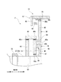
図1に示すように、本実施形態の可変速増速機1は、回転駆動力を発生する電動装置50と、電動装置50で発生した回転駆動力を変速させて駆動対象に伝える変速装置10と、を備えている。可変速増速機1は、例えば、圧縮機システム等の流体機械システムに適用することができる。
本実施形態の可変速増速機1の駆動対象は圧縮機Cである。[First embodiment]
Hereinafter, a variable speed step-up gear according to a first embodiment of the present invention will be described in detail with reference to the drawings.
As shown in FIG. 1, the variable speed step-up
The driving target of the variable speed increaser 1 of the present embodiment is the compressor C.
変速装置10は、遊星歯車変速装置である。
電動装置50は、定速で回転する定速ロータ52を有する定速電動機51と、任意の回転数で回転する可変速ロータ72を有する可変速電動機71とを有している。定速ロータ52と可変速ロータ72は、それぞれ変速装置10と接続されている。The
The
電動装置50は、電動装置支持部50Sによって架台90に支持されている。変速装置10は、変速装置支持部10Sによって架台90に支持されている。これら支持部により、重量物である電動装置50及び変速装置10の確実な固定が可能となる。
The
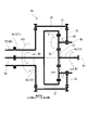
変速装置10は、図2に示すように、水平方向に延在する軸線Arを中心として自転する太陽歯車11と、太陽歯車11に固定されている太陽歯車軸12と、太陽歯車11と噛み合い、軸線Arを中心として公転すると共に自身の中心線Apを中心として自転する複数の遊星歯車15と、軸線Arを中心として環状に複数の歯が並び、複数の遊星歯車15と噛み合う内歯車17と、複数の遊星歯車15を、軸線Arを中心として公転可能に且つ遊星歯車15自身の中心線Apを中心として自転可能に支持する遊星歯車キャリア21と、内歯車17を軸線Arを中心として自転可能に支持する内歯車キャリア31と、これらを覆う変速ケーシング41と、を有している。
As shown in FIG. 2, the
以下、軸線Arが延びている方向を軸方向とし、軸方向の一方側を出力側、出力側の反対側を入力側とする。また、軸線Arを中心とする径方向を単に径方向という。本実施形態の可変速増速機1は、軸線方向の入力側に電動装置50が配置され、電動装置50の出力側に変速装置10が配置されている。圧縮機Cは、可変速増速機1の出力側に配置されている。
Hereinafter, the direction in which the axis Ar extends is defined as the axial direction, one side in the axial direction is defined as the output side, and the opposite side of the output side is defined as the input side. The radial direction centered on the axis Ar is simply referred to as the radial direction. In the
太陽歯車軸12は、軸線Arを中心として円柱状を成し、太陽歯車11から軸方向の出力側に延びている。この太陽歯車軸12の出力側端部には、フランジ13が形成されている。このフランジ13には、例えば、駆動対象としての圧縮機Cのロータが接続される。太陽歯車軸12は、太陽歯車11の出力側に配置されている太陽歯車軸受42により、軸線Arを中心として自転可能に支持されている。太陽歯車軸受42は、変速ケーシング41に取り付けられている。
The
遊星歯車キャリア21は、複数の遊星歯車15毎に設けられている遊星歯車軸22と、複数の遊星歯車軸22相互の位置を固定するキャリア本体23と、軸線Arを中心として軸方向に延びる出力側遊星歯車キャリア軸27oと、を有している。出力側遊星歯車キャリア軸27oは、キャリア本体23の径方向内側に固定されている。
The
遊星歯車軸22は、遊星歯車15の中心線Apを軸方向に貫通し、遊星歯車15をその中心線を中心として自転可能に支持する。キャリア本体23は、複数の遊星歯車軸22から径方向外側に延在している。
The
出力側遊星歯車キャリア軸27oは、キャリア本体23から出力側に延在している。出力側遊星歯車キャリア軸27oは、軸線Arを中心として円筒状を成している。
出力側遊星歯車キャリア軸27oは、遊星歯車キャリア軸受43により、軸線Arを中心として自転可能に支持されている。遊星歯車キャリア軸受43は、変速ケーシング41に取り付けられている。出力側遊星歯車キャリア軸27oの内周側には、太陽歯車軸12が挿通されている。The output-side planetary gear carrier shaft 27o extends from the
The output side planetary gear carrier shaft 27o is supported by a planetary gear carrier bearing 43 so as to be capable of rotating about the axis Ar. The planetary gear carrier bearing 43 is attached to the
変速装置10は、可変速電動機71の可変速ロータ72に接続される入力側遊星歯車キャリア軸27iと、入力側遊星歯車キャリア軸27iの回転を遊星歯車キャリア21に伝達する伝達軸25とを、有している。
入力側遊星歯車キャリア軸27iは、軸線Arを中心として円筒状を成している。入力側遊星歯車キャリア軸27iは、変速装置10の入力側に配置されており、遊星歯車キャリア軸受44により、軸線Arを中心として自転可能に支持されている。遊星歯車キャリア軸受44は、変速ケーシング41に取り付けられている。入力側遊星歯車キャリア軸27iの内周側には、変速装置10の内歯車キャリア31を駆動する内歯車キャリア軸37が挿通されている。
入力側遊星歯車キャリア軸27iの入力側端には、径方向外側に向かって広がる環状のフランジ28が形成されている。入力側遊星歯車キャリア軸27iの出力側端には、径方向外側に向かって延びる入力側アーム部26が形成されている。The
The input side planetary
An
伝達軸25は、軸線Atを中心として自転可能に支持されている。伝達軸25は、軸受(図示せず)を介して変速ケーシング41に取り付けられている。伝達軸25の両端には、入力側伝達歯車29iと出力側伝達歯車29oが固定されている。
入力側伝達歯車29iは、入力側アーム部26の外周に形成されている歯車と噛み合っている。出力側伝達歯車29oは、キャリア本体23の外周に形成されている歯車と噛み合っている。これにより、入力側遊星歯車キャリア軸27iの回転は、伝達軸25を介して遊星歯車キャリア21に伝達される。The
The input side transmission gear 29 i meshes with a gear formed on the outer periphery of the input
内歯車キャリア31は、内歯車17が固定されているキャリア本体33と、キャリア本体33に固定され軸線Arを中心として軸方向に延びる内歯車キャリア軸37と、を有している。
The
キャリア本体33は、軸線Arを中心として円筒状を成し、内周側に内歯車17が固定されている円筒部35と、円筒部35の入力側端と内歯車キャリア軸37の出力側端とを接続するクラッチ機構2と、を有している。
クラッチ機構2は、内歯車キャリア軸37(定速ロータ52)の回転を円筒部35に伝達したり、遮断したりする機構である。The
The
軸線Arを中心として円柱状を成す内歯車キャリア軸37は、軸線Arを中心として円柱状を成す太陽歯車軸12(図2参照)の入力側に配置されている。内歯車キャリア軸37は、円筒状の入力側遊星歯車キャリア軸27i(図2参照)の内周側に挿通されている。
内歯車キャリア軸37の出力側は、内歯車キャリア軸受77によって支持されている。内歯車キャリア軸受77は、ラジアル荷重を受けるラジアル軸受と、スラスト荷重を受けるスラスト軸受とを一体化した複合型軸受である。
内歯車キャリア軸37には、内歯車キャリア軸受77を軸線方向から支持するスラストカラー37aを有している。スラストカラー37aは内歯車キャリア軸37の外周面から径方向外側に突出している。An internal
The output side of the internal
The internal
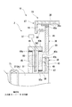
クラッチ機構2は、円筒部35に軸方向に移動可能に接続されている移動部36と、移動部36を軸方向に駆動する駆動部38と、内歯車キャリア軸37(定速ロータ52)に固定されている固定部39と、移動部36が軸方向に移動することにより、移動部36と固定部39とを係合させるハースカップリング40(係合部)と、を有している。
The
駆動部38は、移動部36の入力側に移動部36に対し軸方向に対向するように配置され、移動部36との間に第一油供給空間S1を形成する第一ディスク部45(ディスク)と、第一ディスク部45及び移動部36と協働して第一油供給空間S1を形成する固定シール部49と、第一油供給空間S1に作動油を供給する油供給部57と、を有している。固定シール部49は、円筒形状をなし、変速ケーシング41(図2参照)に固定されている。
The
固定シール部49と第一ディスク45の内部には、径方向に延在する油供給路78が形成されている。油供給路78の径方向外側の端部は、固定シール部49に開口されている。油供給路78の径方向内側の端部は、第一油供給空間S1に油を導入するためのノズル79と接続されている。
An
油供給部57は、変速ケーシング41の内部または外部に設けられており、配管57a及び油供給路78を介して作動油を第一油供給空間S1に供給する。第一油供給空間S1に作動油が供給されることによって、作動油の油圧により、移動部36の第二ディスク部46が入力側から押圧される。第二ディスク部46が入力側から押圧されることによって、移動部36が出力側に移動する。
油供給部57は、内歯車キャリア軸37を支持する軸受に油を供給する油供給装置であってよい。The
The
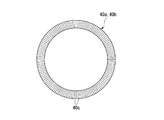
図5に示すように、ハースカップリング40は、移動部36に固定されている第一ハースカップリング40aと、固定部39に固定されている第二ハースカップリング40bと、から構成されている。
移動部36が出力側に移動することにより、第一ハースカップリング40aと第二ハースカップリング40bとが係合する。第一ハースカップリング40aと第二ハースカップリング40bとが係合することによって、内歯車キャリア軸37の回転が固定部39及び移動部36を介して円筒部35に伝達される。
第一ハースカップリング40aと第二ハースカップリング40bとが係合していない状態では、内歯車キャリア軸37の回転は円筒部35に伝達されない。即ち、移動部36が入力側に配置されてハースカップリング40が係合していない状態では、定速ロータ52の駆動力は変速装置10に伝達されない。As shown in FIG. 5, the
When the moving
In a state where the
図6、及び図7に示すように、第一ハースカップリング40a、及び第二ハースカップリング40bは、穴あき円板状の部材である。第一ハースカップリング40a、及び第二ハースカップリング40bの一面には、断面形状が角形(台形状、矩形波状)の爪40cが形成されている。各々の爪40cは、放射状に延在している。複数の爪40cは、周方向に等間隔に形成されている。
第一ハースカップリング40a、及び第二ハースカップリング40bがこのような形状であることによって、例えば、断面形状が三角形の爪と比較して、より強い駆動力の伝達が可能となる。As shown in FIGS. 6 and 7, the
Since the
固定部39は、中心部に貫通孔が形成された円板状の第三ディスク部47と、第三ディスク部47の径方向内側に設けられた円筒形状のボス部58と、を有している。第三ディスク部47の入力側を向く面には、第二ハースカップリング40bが固定されている。
ボス部58の内周面は、内歯車キャリア軸37の外周面に固定されている。固定部39は、第三ディスク部47の主面が軸線Arと直交するように、内歯車キャリア軸37の出力側端に固定されている。The fixed
The inner peripheral surface of the
移動部36は、中心部に貫通孔が形成された円板状の第二ディスク部46と、第二ディスク部46の径方向外側に配置された第四ディスク部48と、第二ディスク部46の径方向外側の端部と、第四ディスク部48の径方向内側の端部とを接続する接続部59と、有している。
第二ディスク部46は、固定部39の第三ディスク部47の入力側に、第二ディスク部46の主面と第三ディスク部47の主面とが互いに平行となるように配置されている。
第二ディスク部46の内周面と、ボス部58の外周面との間には、シール部材60aが設けられている。シール部材60aは、作動油が第一油供給空間S1から流出するのを制限する機能を有する、例えば、グランドパッキンである。The moving
The
A
第二ディスク部46の出力側を向く面には、第一ハースカップリング40aが固定されている。第二ディスク部46の外周面と固定シール部49の内周面との間にはシール部材60bが設けられている。
接続部59は、第二ディスク部46の径方向外側の端部から出力側に突出している。第四ディスク部48の外周面は、円筒部35の内周面に軸方向に移動可能に接続されている。
第四ディスク部48と円筒部35とは、周方向に相対移動不能に接続されている。具体的には、第四ディスク部48の外周面には、軸線Arと平行な直線歯である第一平歯車48aが形成され、円筒部35の内周面には、第四ディスク部48の第一平歯車48aと噛み合う第二平歯車35aが形成されている。第四ディスク部48(移動部36)は、第二平歯車35a上を第一平歯車48aが移動することによって、軸方向に移動する。A
The connecting
The
移動部36は、付勢機構67によって入力側に付勢されている。付勢機構67は、円筒部35の入力側の端部に固定されている複数のばね固定部材68と、複数の引張コイルばね69とを有している。バネ固定部材68は、周方向に間隔を開けて複数固定されている。
バネ固定部材68は、円筒部35の内周面から径方向内側に突出している。バネ固定部材68は、第四ディスク部48の入力側に配置されている。引張コイルばね69は、ばね固定部材68と、第四ディスク部48とを接続している。引張コイルばね69によって移動部36は、入力側に付勢される。The moving
The
第一ディスク部45は、移動部36の第二ディスク部46の入力側に、第一ディスク部45の主面と第二ディスク部46の主面とが互いに平行となるように配置されている。第一ディスク部45の外周面は、固定シール部49の内周面に固定されている。
第一ディスク部45の内周面と内歯車キャリア軸37の外周面との間にはシール部材60cが設けられている。The
A
第一油供給空間S1は、第一ディスク部45と第二ディスク部46と固定シール部49によって形成される密閉空間である。移動部36が軸方向に移動することにより、第一油供給空間S1の容積は増加したり減少したりする。即ち、移動部36が、入力側に移動することにより、第一油供給空間S1の容積は増加し、移動部36が、出力側に移動することにより、第一油供給空間S1の容積は減少する。
The first oil supply space S <b> 1 is a sealed space formed by the
図4に示すように、固定シール部49の下端には、第一油供給空間S1内の作動油を排出するための油排出機構70(油排出部)が設けられている。油排出機構70は、制御装置3によって制御可能な弁を有している。
As shown in FIG. 4, an oil discharge mechanism 70 (oil discharge portion) for discharging the working oil in the first oil supply space S <b> 1 is provided at the lower end of the fixed
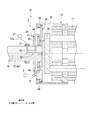
図3に示すように、定速電動機51は、変速装置10の内歯車キャリア軸37を回転駆動させる。可変速電動機71は、変速装置10の入力側遊星歯車キャリア軸27iを回転駆動させる。電動装置50は、定速電動機51を冷却するための冷却ファン91と、冷却ファン91を覆うファンカバー92と、を有する。
As shown in FIG. 3, the
内歯車キャリア軸37は、定速電動機51の駆動力によって定速で回転する定速入力軸Acである。入力側遊星歯車キャリア軸27iは、可変速電動機71の駆動力によって任意の回転数で回転する可変速入力軸Avである。
可変速増速機1は、可変速電動機71の回転数を変えることによって、駆動対象に接続される変速装置10の出力軸Aoの回転数を変えることができる。The internal
The
本実施形態において、定速電動機51は、例えば、4極の三相誘導電動機である。また、可変速電動機71は、極数が定速電動機51よりも多い8極の三相誘導電動機である。なお、定速電動機51及び可変速電動機71の仕様はこれに限ることはなく、適宜仕様を変更することができる。
In the present embodiment, the
定速電動機51は、軸線Arを中心として自転し、変速装置10の定速入力軸Acである内歯車キャリア軸37に接続される定速ロータ52と、定速ロータ52の外周側に配置されている定速ステータ66と、定速ステータ66が内周側に固定されている定速電動機ケーシング61と、を有している。
The
定速ロータ52は、軸線Arを中心として円柱状を成す定速ロータ軸53と、定速ロータ軸53の外周に固定されている導体56と、を有する。定速ロータ軸53の入力側端には、冷却ファン91が固定されている。
The constant-
定速ステータ66は、定速ロータ52の導体56の径方向外側に配置されている。この定速ステータ66は、複数のコイルで形成されている。
The
定速電動機ケーシング61は、軸線Arを中心として円筒状を成し、内周側に定速ステータ66が固定されているケーシング本体62と、円筒状のケーシング本体62の軸方向の両端を塞ぐ蓋63i,63oとを有している。各々の蓋63i,63oには、定速ロータ軸53を、軸線Arを中心として自転可能に支持する定速ロータ軸受65i,65oが取り付けられている。各々の蓋63i,63oには、定速ロータ軸受65iよりも径方向外側の位置で、軸方向に貫通する複数の開口64が形成されている。
The constant-
定速ロータ軸53の入力側端は、定速電動機ケーシング61の入力側の蓋63iから、入力側に突出している。定速ロータ軸53の入力側端に、冷却ファン91が固定されている。
定速ロータ52が回転すると、冷却ファン91も定速ロータ52と一体的に回転する。ファンカバー92は、冷却ファン91の外周側に配置されている円筒状のカバー本体93と、カバー本体93の入口側の開口に取り付けられ、複数の空気孔が形成されている空気流通板94と、を有する。ファンカバー92は、定速電動機ケーシング61の入力側の蓋63iに固定されている。The input side end of the constant
When the
可変速電動機71は、軸線Arを中心として自転し、可変速入力軸Avである入力側遊星歯車キャリア軸27iに接続される可変速ロータ72と、可変速ロータ72の外周側に配置されている可変速ステータ86と、可変速ステータ86が内周側に固定されている可変速電動機ケーシング81と、を有している。
The
可変速ロータ72は、可変速ロータ軸73と、可変速ロータ軸73の外周に固定されている導体76と、を有している。可変速ロータ軸73は、軸線Arを中心として円筒状を成し、軸方向に貫通した軸挿通孔74を有している。可変速ロータ軸73の軸挿通孔74には、定速入力軸Acである内歯車キャリア軸37が挿通されている。可変速ロータ軸73の出力側端には、径方向外側に向かって広がる環状のフランジ73oが形成されている。
The
可変速ステータ86は、可変速ロータ72の導体76の径方向外側に配置されている。可変速ステータ86は、複数のコイルで形成されている。
The
可変速電動機ケーシング81は、軸線Arを中心として円筒状を成し、内周側に可変速ステータ86が固定されているケーシング本体82と、円筒状のケーシング本体82の出力側端を塞ぐ出力側蓋83oと、可変速ステータ86よりも入力側に配置され円筒状のケーシング本体82の内周側に固定されている入口側蓋83iと、を有している。各々の蓋83i,83oには、可変速ロータ軸73を、軸線Arを中心として自転可能に支持する可変速ロータ軸受85i,85oが取り付けられている。各々の蓋83i,83oには、可変速ロータ軸受85i,85oよりも径方向外側の位置で、軸方向に貫通する複数の開口84が形成されている。
The variable
可変速電動機ケーシング81の各々の蓋83i,83oに形成されている複数の開口84、及び、定速電動機ケーシング61の各蓋63i,63oに形成されている複数の開口64により、可変速電動機ケーシング81内の空間と定速電動機ケーシング61内の空間とが連通している。
A plurality of
本実施形態の可変速増速機1は、可変速入力軸Avである入力側遊星歯車キャリア軸27iと可変速ロータ72との間に配置され、両者を接続する可変速用フレキシブルカップリング95を備えている。
また、本実施形態の可変速増速機1において、定速ロータ52と、可変速ロータ72と、太陽歯車軸12とは同一の軸線上に配置されている。The
In the
図8に示すように、定速電動機51は、定速電動機51に電力を供給することによって定速ロータ52(内歯車17)を軸線Arの周方向の第二方向R2に回転させるように設定されている。定速ロータ52が第二方向R2に回転することによって、内歯車キャリア軸37及び内歯車キャリア31は、第二方向R2に回転する。
As shown in FIG. 8, the
変速装置10の出力軸Aoは、定速電動機51の定速ロータ52が第二方向R2に最大回転数で回転することにより、第二方向R2とは逆方向の第一方向R1に回転するように設定されている。即ち、定速電動機51の正回転は第二方向R2であり、変速装置10の出力軸Aoの正回転は、第一方向R1である。圧縮機Cは、出力軸Aoが正回転することにより、正常に作動する。
なお、以下の説明においては、第一方向R1の回転方向をプラスの回転方向とし、第二方向R2の回転方向をマイナスの回転方向とする。例えば、定速電動機51の最大回転数は、−1800rpmである。The output shaft Ao of the
In the following description, the rotation direction of the first direction R1 is a positive rotation direction, and the rotation direction of the second direction R2 is a negative rotation direction. For example, the maximum rotation speed of the
可変速電動機71は、可変速ロータ72(遊星歯車キャリア21)を軸線Arの周方向の第一方向R1及び第二方向R2に回転駆動させることができる。即ち、可変速電動機71は、正回転及び逆回転が可能である。
可変速電動機71は、可変速ロータ72を外部の力で回転させることによって発電機として機能する。可変速電動機71が発電機として機能する状態を発電機モードと呼ぶ。
可変速電動機71は、電力が供給されることによって電動機として機能する。可変速電動機71が電動機として機能する状態を電動機モードと呼ぶ。
可変速ロータ72が第一方向R1に回転することによって、遊星歯車キャリア21は、第一方向R1に回転する。The variable speed
The
The
As the
本実施形態の可変速増速機1は、可変速電動機71の回転数を制御する回転数制御装置100と、可変速電動機71を電力供給状態と電力断状態とにする可変速電動機スイッチ111と、定速電動機51を電力供給状態と電力断状態とにする定速電動機スイッチ112と、回転数制御装置100、可変速電動機スイッチ111及び定速電動機スイッチ112の動作を制御する制御部120と、を備えている。
The
制御部120は、コンピュータで構成されている。制御部120は、オペレータからの指示を直接受け付ける又は上位制御装置からの指示を受け付ける受付部121と、可変速電動機スイッチ111及び回転数制御装置100、定速電動機スイッチ112に指示を与えるインタフェース122と、受付部121で受け付けた指示等に応じて、可変速電動機スイッチ111、定速電動機スイッチ112及び回転数制御装置100に対する指示を作成する演算部123と、を有している。
The
可変速電動機スイッチ111は、電源線110と回転数制御装置100とに電気的に接続されている。回転数制御装置100は、可変速電動機71と電気的に接続されている。定速電動機スイッチ112は、電源線110と定速電動機51とに電気的に接続されている。
The variable
可変速電動機スイッチ111は、制御部120からのオン指示でオンになり、制御部120からのオフ指示でオフになる。可変速電動機スイッチ111がオンになると、電源線110からの電力が回転数制御装置100を介して可変速電動機71に供給され、可変速電動機71は電力供給状態になる。可変速電動機スイッチ111がオフになると、電源線110から回転数制御装置100及び可変速電動機71への電力供給が断たれ、可変速電動機71は電力断状態になる。
The variable
定速電動機スイッチ112は、制御部120からのオン指示でオンになり、制御部120からのオフ指示でオフになる。定速電動機スイッチ112がオンになると、電源線110からの電力が定速電動機51に供給され、定速電動機51は電力供給状態になる。定速電動機スイッチ112がオフになると、電源線110から定速電動機51への電力供給が断たれ、定速電動機51は電力断状態になる。
The constant
回転数制御装置100は、電源線110から供給される電力の周波数を変える周波数変換部101と、可変速電動機71の回転方向を変更する回転方向変更部102と、を備えている。
周波数変換部101は、制御部120から指示された周波数の電力を可変速電動機71に供給する。可変速電動機71の可変速ロータ72は、この周波数に応じた回転数で回転する。このように、可変速ロータ72の回転数が変化するため、可変速ロータ72に接続されている変速装置10の遊星歯車キャリア21の回転数も変化する。この結果、変速装置10の出力軸Aoである太陽歯車軸12の回転数も変化する。
回転方向変更部102は、可変速電動機71に接続されている複数(本実施形態の場合3本)の電源線を入れ替える回路を用いることによって、可変速電動機71の回転方向を変更する装置である。即ち、回転方向変更部102は、可変速ロータ72を正回転、及び逆回転させることができる。The rotation
The
The rotation
ここで、変速装置10の各歯車の歯数と、変速装置10の各軸の回転数との関係について、図8を用いて説明する。
Here, the relationship between the number of teeth of each gear of the
出力軸Aoとしての太陽歯車軸12の回転数をωs、定速入力軸Acとしての内歯車キャリア軸37(定速電動機51)の回転数をωi、可変速入力軸Avとしての入力側遊星歯車キャリア軸27i(可変速電動機71)の回転数をωhとする。また、太陽歯車11の歯数をZs、内歯車17の歯数をZiとする。
また、出力軸Aoの回転数ωsと定速電動機51の回転数ωiの比ωs/ωiをUとする。出力軸Aoの回転数ωsと定速電動機51の回転数ωiの比Uは、内歯車17の歯数Ziと太陽歯車11の歯数Zsの比Zi/Zsと同じである。
また、遊星歯車キャリア21の回転数ωcと可変速電動機71の回転数ωhの比ωc/ωhをPとする。The rotational speed of the
Further, U is the ratio ωs / ωi between the rotational speed ωs of the output shaft Ao and the rotational speed ωi of the
Also, let P be the ratio ωc / ωh of the rotational speed ωc of the
各歯車の歯数と、変速装置10の各軸の回転数との関係は、以下の式(1)で表すことができる。
ωs/ωi=P×ωh/ωi−(1−P×ωh/ωi )×U ・・・(1)The relationship between the number of teeth of each gear and the number of rotations of each shaft of the
ωs / ωi = P × ωh / ωi− (1−P × ωh / ωi) × U (1)
仮に、定速電動機51が4極の誘導電動機で、電源周波数が60Hzの場合、定速ロータ52(定速入力軸Ac)の回転数ωi(定格回転数)は−1800rpmとなる。また、可変速電動機71が8極の誘導電動機で、電源周波数が60Hzの場合、可変速ロータ72(可変速入力軸Av)の最高回転数ωh(定格回転数)は900rpmとなる。
また、仮に、出力軸Aoの回転数ωsと定速電動機51の回転数ωiの比U(太陽歯車11の歯数Zsと内歯車17の歯数Ziと比Zi/Zs)を4とする。
また、遊星歯車キャリア21の回転数ωcと可変速電動機71の回転数ωhの比Pを0.3とする。If the
Further, it is assumed that the ratio U (the number of teeth Zs of the
Further, a ratio P between the rotational speed ωc of the
この場合、定速ロータ52(内歯車17)の回転の向きを第二方向R2の回転(−1800rpm)とし、可変速ロータ72(遊星歯車キャリア21)の回転の向きが定速ロータ52の回転と逆向き(第一方向R1の回転)の最高回転数(900rpm)であると、出力軸Aoである太陽歯車軸12の回転数ωsは、11700rpmとなる。この回転数(11700rpm)は、太陽歯車軸12の最高回転数である。
即ち、本実施形態の変速装置10においては、定速入力軸Acに対応する内歯車17を−1800rpmで回転させ、可変速入力軸Avに対応する遊星歯車キャリア21を900rpmで回転させることによって、出力軸Aoの回転数ωsが最高回転数となる。
可変速入力軸Avの可変速範囲が−900rpmから+900rpmであるとすると、可変速入力軸Avの回転数が−900rpmに近づくに従って、出力軸Aoの回転数ωsは低くなる。In this case, the rotation direction of the constant speed rotor 52 (internal gear 17) is the rotation in the second direction R2 (−1800 rpm), and the rotation direction of the variable speed rotor 72 (the planetary gear carrier 21) is the rotation of the
That is, in the
Assuming that the variable speed range of the variable speed input shaft Av is from −900 rpm to +900 rpm, the rotational speed ωs of the output shaft Ao decreases as the rotational speed of the variable speed input shaft Av approaches −900 rpm.
次に、本実施形態の可変速増速機1の動作について説明する。
本実施形態の可変速増速機1は、クラッチ機構2を用いて、定速電動機51の駆動力を変速装置10に伝達させないようにすることができる。
図5に示すように、通常運転の際は、クラッチ機構2によって定速電動機51(図1参照)の駆動力は、変速装置10に伝達される。通常運転の際は、油供給部57(図4参照)から第一油供給空間S1に作動油が供給されて移動部36が出力側に移動している。移動部36が出力側に移動することによって、ハースカップリング40を構成する第一ハースカップリング40aと第二ハースカップリング40bとが係合する。これにより、定速電動機51の駆動力は、定速ロータ52(図1参照)、内歯車キャリア軸37、固定部39、及び移動部36を介して円筒部35に伝達される。Next, operation | movement of the
The variable speed step-up
As shown in FIG. 5, during normal operation, the driving force of the constant speed motor 51 (see FIG. 1) is transmitted to the
図9に示すように、クラッチ機構2を用いて、定速電動機51の駆動力を変速装置10に伝達させないようにする場合は、制御装置3は、油排出機構70(図4参照)を制御して第一油供給空間S1内の作動油を排出する。これにより、移動部36が入力側に移動する。移動部36が入力側に移動することによって、第一ハースカップリング40aと第二ハースカップリング40bとが離間して、定速ロータ52側の駆動力が円筒部35に伝達されなくなる。
As shown in FIG. 9, when the
上記実施形態によれば、可変速増速機1において、例えば、過電圧、過電流などが原因で電動機への電力供給が遮断される場合に、変速装置10に伝達される定速電動機51の駆動力を切断することができる。
これにより、定速ロータ52の回転が伝達することにより、可変速電動機71や駆動対象である圧縮機Cが過回転するのを防止することができる。According to the above embodiment, in the
As a result, the rotation of the
また、油圧により移動部36を移動させる構成とすることによって、軸受に供給する油を用いて移動部36を移動させることができる。また、第一油供給空間S1から油を排出することによって、ハースカップリング40による係合を解除することができる。
Further, by adopting a configuration in which the moving
また、本実施形態では、軸挿通孔74が形成された円筒状の軸である可変速ロータ軸73に棒状の軸である内歯車キャリア軸37が挿通されている。即ち、出力の大きな定速入力軸Acが定速電動機51よりも出力の小さい可変速電動機71の可変速ロータ軸73に挿通されている。これにより、定速電動機51としてより大きな出力(馬力)のあるものを採用することができる。
また、本実施形態では、定速電動機51、可変速電動機71、変速装置、圧縮機Cの順に直線状に配置していることにより、装置全体をよりコンパクトにすることができる。In the present embodiment, the internal
Moreover, in this embodiment, since the
[第二実施形態]
以下、本発明の第二実施形態の可変速増速機について図面を参照して詳細に説明する。なお、本実施形態では、上述した第一実施形態との相違点を中心に述べ、同様の部分についてはその説明を省略する。
本実施形態の可変速増速機の第一ディスク部45は、移動部36と同様に、軸方向に移動可能である。[Second Embodiment]
Hereinafter, the variable speed step-up gear according to the second embodiment of the present invention will be described in detail with reference to the drawings. In the present embodiment, differences from the first embodiment described above will be mainly described, and description of similar parts will be omitted.
Similar to the moving
第一ディスク部45は、図示しないレールを介して変速ケーシング41(図2参照)に接続されている。第一ディスク部は、レールに沿って軸方向に移動する。
The
内歯車キャリア軸37には、スラストカラー37bが形成されており、第一ディスク部45の入力側を向く面45aは、スラスト軸受87を介してスラストカラー37bに支持されている。
A
油供給路78の径方向内側の開口(ノズル)は第一ディスク部45の内周面に設けられている。第一ディスク部45の外周面と固定シール部49の内周面との間には、シール部材60dが設けられている。
An opening (nozzle) on the radially inner side of the
上記実施形態によれば、第一ディスク部45を軸方向に移動可能な部品とすることによって、第一油供給空間S1にかかる油圧力をスラスト軸受87及びスラストカラー37bにて受けることができる。これにより、固定部39が受ける力とスラストカラー37bが受ける力とが打ち消し合うことで、内歯車キャリア軸37にかかる力をキャンセルすることができる。
According to the above embodiment, by making the
[第三実施形態]
以下、本発明の第三実施形態の可変速増速機について図面を参照して詳細に説明する。なお、本実施形態では、上述した第一実施形態との相違点を中心に述べ、同様の部分についてはその説明を省略する。
図11に示すように、本実施形態の第一ディスク部45の内周面は、内歯車キャリア軸37の外周面に固定されている。即ち、本実施形態の第一ディスク部45は、内歯車キャリア軸37とともに回転する。[Third embodiment]
Hereinafter, a variable speed step-up gear according to a third embodiment of the present invention will be described in detail with reference to the drawings. In the present embodiment, differences from the first embodiment described above will be mainly described, and description of similar parts will be omitted.
As shown in FIG. 11, the inner peripheral surface of the
第一ディスク部45の外周面と固定シール部49の内周面との間にはシール部材60eが設けられている。
本実施形態の油供給路78Cは、固定シール部49のみに形成されている。
第一油供給空間S1の内部には、給油ノズル88が設けられている。給油ノズル88は、固定シール部49と同様に、静止部材である。
給油ノズル88は円筒状をなしており、径方向に延在している。給油ノズル88の径方向外側の端部は、固定シール部49の内周面に形成されている油供給路78Cの開口と接続されている。給油ノズル88は、内歯車キャリア軸37の外周面の近傍まで延在している。A
The
An
The
上記実施形態によれば、給油ノズル88を用いて、油にかかる遠心力により圧力が高くなる径方向外側ではなく、より圧力が低い径方向内側から油を供給することができる。
According to the above embodiment, the
[第四実施形態]
以下、本発明の第四実施形態の可変速増速機について図面を参照して詳細に説明する。なお、本実施形態では、上述した第三実施形態との相違点を中心に述べ、同様の部分についてはその説明を省略する。
図12に示すように、本実施形態の内歯車キャリア軸37の内部には、第二油供給空間S2が形成されている。第二油供給空間S2は、内歯車キャリア軸37の出力側端部に形成されている密閉空間である。第一油供給空間S1と第二油供給空間S2とは、連通路S3によって連通されている。[Fourth embodiment]
Hereinafter, a variable speed step-up gear according to a fourth embodiment of the present invention will be described in detail with reference to the drawings. In this embodiment, the difference from the above-described third embodiment will be mainly described, and the description of the same parts will be omitted.
As shown in FIG. 12, a second oil supply space S2 is formed inside the internal
油供給部57は、変速ケーシング41の内部または外部に設けられており、配管57aを介して作動油を第二油供給空間S2に供給する。油供給部57より、第二油供給空間S2に作動油が供給されることによって、連通路S3を介して第一油供給空間S1に径方向内側から作動油が供給される。第一油供給空間S1に作動油が供給されることによって、作動油の油圧により、移動部36の第二ディスク部46が入力側から押圧される。第二ディスク部46が入力側から押圧されることによって、移動部36が出力側に移動する。
油供給部57は、内歯車キャリア軸37を支持する軸受に油を供給する油供給装置であってよい。The
The
図13に示すように、通常運転の際は、クラッチ機構2によって定速電動機51(図1参照)の駆動力は、変速装置10に伝達される。通常運転の際は、油供給部57(図4参照)から第二油供給空間S2及び連通路S3を介して第一油供給空間S1に作動油が供給されて移動部36が出力側に移動している。
As shown in FIG. 13, during normal operation, the driving force of the constant speed motor 51 (see FIG. 1) is transmitted to the
上記実施形態によれば、油にかかる遠心力により圧力が高くなる第一油供給空間S1ではなく、より圧力が低い第二油供給空間S2から油を供給する構成としたことによって、容易に油供給空間S1,S2に油を供給することができる。 According to the above-described embodiment, the oil is easily supplied from the second oil supply space S2 having a lower pressure rather than the first oil supply space S1 in which the pressure is increased by the centrifugal force applied to the oil. Oil can be supplied to the supply spaces S1, S2.
なお、上記実施形態では、移動部36を、円筒部35に軸方向に移動可能に接続する構成としているがこれに限ることはなく、移動部36を、内歯車キャリア軸37に軸方向に移動可能に接続する構成としてもよい。この場合、固定部39は、円筒部35に固定される。
In the above embodiment, the moving
また、上記実施形態では、圧縮機Cを高速回転させるために好適な定速電動機51として、4極の三相誘導電動機を例示し、圧縮機Cの回転数を一定の範囲内で可変速させるために好適な可変速電動機71として、8極の三相誘導電動機を例示している。しかしながら、駆動対象を高速回転させる必要がない場合には、定速電動機51や可変速電動機71として他のタイプの電動機を用いてもよい。
In the above-described embodiment, a four-pole three-phase induction motor is exemplified as the constant-
1 可変速増速機
2 クラッチ機構
10 変速装置
10S 変速装置支持部
11 太陽歯車
12 太陽歯車軸
15 遊星歯車
17 内歯車
21 遊星歯車キャリア
22 遊星歯車軸
25 伝達軸
27 遊星歯車キャリア軸
27i 入力側遊星歯車キャリア軸
27o 出力側遊星歯車キャリア軸
28 フランジ
31 内歯車キャリア
33 キャリア本体
35 円筒部
35a 第二平歯車
36 移動部
37 内歯車キャリア軸
38 駆動部
39 固定部
40 ハースカップリング(係合部)
40a 第一ハースカップリング
40b 第二ハースカップリング
40c 爪(ハースカップリング)
41 変速ケーシング
42 太陽歯車軸受
45 第一ディスク部
46 第二ディスク部
47 第三ディスク部
48 第四ディスク部
48a 第一平歯車
49 固定シール部
50 電動装置
50S 電動装置支持部
51 定速電動機
52 定速ロータ
53 定速ロータ軸
56 導体
57 油供給部
57a 配管
58 ボス部
59 接続部
60a シール部材
60b シール部材(第二ディスク部)
60c シール部材(第一ディスク部)
60d シール部材(第一ディスク部)
60e シール部材(第一ディスク部)
61 定速電動機ケーシング
64 開口(定速電動機ケーシング)
66 定速ステータ
67 付勢機構
68 ばね固定部材
69 引張コイルばね
70 油排出機構(油排出部)
71 可変速電動機
72 可変速ロータ
73 可変速ロータ軸
74 軸挿通孔
76 導体
77 内歯車キャリア軸受
78,78C 油供給路
79 ノズル
81 可変速電動機ケーシング
84 開口(可変速電動機ケーシング)
86 可変速ステータ
87 スラスト軸受
88 給油ノズル
90 架台
91 冷却ファン
100 回転数制御装置
101 周波数変換部
102 回転方向変更部
110 電源線
111 可変速電動機スイッチ
112 定速電動機スイッチ
120 制御部(制御装置)
121 受付部
122 インタフェース
123 演算部
Ac 定速入力軸
Ao 出力軸
Ap 中心線(遊星歯車軸)
Ar 軸線
Av 可変速入力軸
C 圧縮機
R1 第一方向
R2 第二方向
S1 第一油供給空間
S2 第二油供給空間
S3 連通路DESCRIPTION OF
40a
41
60c Seal member (first disk part)
60d Seal member (first disk part)
60e Seal member (first disk part)
61 Constant
66 Constant-
DESCRIPTION OF
86
121
Ar Axis line Av Variable speed input shaft C Compressor R1 First direction R2 Second direction S1 First oil supply space S2 Second oil supply space S3 Communication path
Claims (5)
前記電動装置で発生した回転駆動力を変速させて駆動対象に伝える変速装置と、
を備え、
前記変速装置は、
軸線を中心として自転する太陽歯車と、
前記太陽歯車に固定され、前記軸線を中心として、軸方向に延びる太陽歯車軸と、
前記太陽歯車と噛み合い、前記軸線を中心として公転すると共に自身の中心線を中心として自転する遊星歯車と、
前記軸線を中心として環状に複数の歯が並び、前記遊星歯車と噛み合う内歯車と、
前記軸線を中心として軸方向に延びる遊星歯車キャリア軸を有し、前記遊星歯車を、前記軸線を中心として公転可能に且つ前記遊星歯車自身の中心線を中心として自転可能に支持する遊星歯車キャリアと、
前記軸線を中心として軸方向に延びる内歯車キャリア軸を有し、前記内歯車を、前記軸線を中心として自転可能に支持する内歯車キャリアと、
を有し、
前記太陽歯車軸が前記駆動対象に接続される出力軸を成し、前記内歯車キャリア軸が定速入力軸を成し、前記遊星歯車キャリア軸が可変速入力軸を成し、
前記電動装置は、
前記変速装置の前記定速入力軸を回転させる定速ロータを有する定速電動機と、
前記変速装置の前記可変速入力軸に接続されている可変速ロータを有する可変速電動機と、を有し、
前記内歯車キャリアは、前記内歯車に接続された円筒部と前記内歯車キャリア軸とを接続するクラッチ機構を備え、
前記クラッチ機構は、前記円筒部と前記内歯車キャリア軸との一方に軸方向に移動可能に接続されている移動部と、
前記移動部を軸方向に駆動する駆動部と、
前記円筒部と前記内歯車キャリア軸との他方に固定されている固定部と、
前記移動部が軸方向に移動することにより、前記移動部と前記固定部とを係合させる係合部と、を有する可変速増速機。An electric device that generates rotational driving force;
A transmission that shifts the rotational driving force generated by the electric device and transmits it to a drive target;
With
The transmission is
A sun gear that rotates about its axis,
A sun gear shaft fixed to the sun gear and extending in the axial direction around the axis;
A planetary gear that meshes with the sun gear, revolves around the axis and rotates around its centerline;
A plurality of teeth arranged in a ring around the axis, and an internal gear meshing with the planetary gear,
A planetary gear carrier having a planetary gear carrier shaft extending in the axial direction about the axis, and supporting the planetary gear so that it can revolve around the axis and rotate around the centerline of the planetary gear itself; ,
An internal gear carrier shaft that extends in the axial direction about the axis, and supports the internal gear so that it can rotate about the axis; and
Have
The sun gear shaft forms an output shaft connected to the drive target, the internal gear carrier shaft forms a constant speed input shaft, the planetary gear carrier shaft forms a variable speed input shaft,
The electric device is
A constant speed motor having a constant speed rotor for rotating the constant speed input shaft of the transmission;
A variable speed motor having a variable speed rotor connected to the variable speed input shaft of the transmission,
The internal gear carrier includes a clutch mechanism that connects the cylindrical portion connected to the internal gear and the internal gear carrier shaft,
The clutch mechanism includes a moving part connected to one of the cylindrical part and the internal gear carrier shaft so as to be movable in the axial direction;
A drive unit for driving the moving unit in an axial direction;
A fixed portion fixed to the other of the cylindrical portion and the internal gear carrier shaft;
A variable speed step-up gear having an engaging portion that engages the moving portion and the fixed portion by moving the moving portion in the axial direction.
前記円筒部と前記内歯車キャリア軸との他方に前記移動部に対し軸方向に対向するように固定され、前記移動部との間に油供給空間を形成するディスクと、
前記油供給空間に油を供給する油供給部と、
前記油供給空間から油を排出する油排出部と、を有する請求項1に記載の可変速増速機。The drive unit is
A disk that is fixed to the other of the cylindrical portion and the internal gear carrier shaft so as to face the moving portion in the axial direction, and that forms an oil supply space between the moving portion;
An oil supply section for supplying oil to the oil supply space;
The variable speed gearbox according to claim 1, further comprising: an oil discharge unit that discharges oil from the oil supply space.
前記第一油供給空間と連通し、前記定速ロータの内部に形成された第二油供給空間と、を有し、
前記油供給部は、前記第二油供給空間に油を供給する請求項2に記載の可変速増速機。The oil supply space is a first oil supply space formed between the moving part and the disk;
A second oil supply space that communicates with the first oil supply space and is formed inside the constant speed rotor;
The variable speed gearbox according to claim 2, wherein the oil supply unit supplies oil to the second oil supply space.
Applications Claiming Priority (1)
| Application Number | Priority Date | Filing Date | Title |
|---|---|---|---|
| PCT/JP2016/071248 WO2018016021A1 (en) | 2016-07-20 | 2016-07-20 | Variable speed gearbox |
Publications (2)
| Publication Number | Publication Date |
|---|---|
| JPWO2018016021A1 JPWO2018016021A1 (en) | 2019-04-04 |
| JP6566433B2 true JP6566433B2 (en) | 2019-08-28 |
Family
ID=60993263
Family Applications (2)
| Application Number | Title | Priority Date | Filing Date |
|---|---|---|---|
| JP2018528140A Active JP6566433B2 (en) | 2016-07-20 | 2016-07-20 | Variable speed gearbox |
| JP2018528190A Active JP6635622B2 (en) | 2016-07-20 | 2016-11-17 | Variable speed gearbox, control device for variable speed gearbox, and control method for variable speed gearbox |
Family Applications After (1)
| Application Number | Title | Priority Date | Filing Date |
|---|---|---|---|
| JP2018528190A Active JP6635622B2 (en) | 2016-07-20 | 2016-11-17 | Variable speed gearbox, control device for variable speed gearbox, and control method for variable speed gearbox |
Country Status (4)
| Country | Link |
|---|---|
| US (2) | US20200318714A1 (en) |
| JP (2) | JP6566433B2 (en) |
| DE (1) | DE112016006959B4 (en) |
| WO (2) | WO2018016021A1 (en) |
Families Citing this family (10)
| Publication number | Priority date | Publication date | Assignee | Title |
|---|---|---|---|---|
| US10605338B2 (en) * | 2016-02-26 | 2020-03-31 | Mitsubishi Heavy Industries Compressor Corporation | Variable-speed speed increaser |
| WO2017145367A1 (en) * | 2016-02-26 | 2017-08-31 | 三菱重工コンプレッサ株式会社 | Variable speed accelerator |
| JP6627184B2 (en) | 2016-06-15 | 2020-01-08 | 三菱重工コンプレッサ株式会社 | Variable speed gearbox |
| DE112016006977B4 (en) * | 2016-06-15 | 2022-05-25 | Mitsubishi Heavy Industries Compressor Corporation | VARIABLE SPEED ACCELERATOR WITH TWO MOTORS AND SUPERFERENCE GEARING AND METHOD OF OPERATING SUCH |
| WO2017216888A1 (en) * | 2016-06-15 | 2017-12-21 | 三菱重工コンプレッサ株式会社 | Variable speed accelerator and method for starting variable speed accelerator |
| WO2018016021A1 (en) | 2016-07-20 | 2018-01-25 | 三菱重工コンプレッサ株式会社 | Variable speed gearbox |
| WO2018029804A1 (en) * | 2016-08-10 | 2018-02-15 | 三菱重工コンプレッサ株式会社 | Variable speed-increaser |
| DE102019102881B4 (en) * | 2019-02-06 | 2022-06-02 | Renk Gmbh | Method and control device for operating a drive train with a main and auxiliary drive and superimposed gear |
| JP2023122881A (en) * | 2022-02-24 | 2023-09-05 | 三菱重工コンプレッサ株式会社 | Rotating machine system and maintenance method of rotating machine |
| DE102022109970A1 (en) * | 2022-04-26 | 2023-10-26 | Audi Aktiengesellschaft | Geared motor for a motor vehicle and motor vehicle with a geared motor |
Family Cites Families (30)
| Publication number | Priority date | Publication date | Assignee | Title |
|---|---|---|---|---|
| US2519042A (en) | 1948-10-07 | 1950-08-15 | Sundstrand Machine Tool Co | Automatic positive stop and dwell arrangement for machine tools |
| JPH0646064B2 (en) * | 1984-09-18 | 1994-06-15 | 石川島播磨重工業株式会社 | Fitting device |
| JP2888938B2 (en) | 1990-06-29 | 1999-05-10 | マツダ株式会社 | Automatic transmission |
| JP4046297B2 (en) | 1996-02-01 | 2008-02-13 | 多摩川精機株式会社 | Differential planetary double speed sensor |
| JPH10238381A (en) | 1997-02-25 | 1998-09-08 | Denso Corp | Hybrid vehicle control device |
| US6018694A (en) | 1996-07-30 | 2000-01-25 | Denso Corporation | Controller for hybrid vehicle |
| US7004868B2 (en) * | 2001-07-23 | 2006-02-28 | Nissan Motor Co., Ltd. | Drivetrain for a vehicle |
| DE60334605D1 (en) * | 2002-02-21 | 2010-12-02 | Ebara Corp | Starting device comprising a planetary differential gear device and starting method for a planetary differential gear device |
| JP4183481B2 (en) | 2002-11-01 | 2008-11-19 | 有限会社クチダギアリング | Transmission |
| JP4779341B2 (en) | 2004-11-18 | 2011-09-28 | トヨタ自動車株式会社 | Piston for automatic transmission |
| US7559415B2 (en) | 2006-02-03 | 2009-07-14 | Borgwarner Inc. | Hydraulic synchronizer |
| JP2010242811A (en) | 2009-04-02 | 2010-10-28 | Kuchida Gearing:Kk | Transmission |
| US10454394B2 (en) * | 2014-07-18 | 2019-10-22 | Mitsubishi Heavy Industries Compressor Corporation | Rotational driving force imparting device and electric motor device for the same |
| AT517170B1 (en) | 2015-04-27 | 2019-07-15 | Set Sustainable Energy Tech Gmbh | Method for starting a drive train |
| DE102015107934A1 (en) | 2015-05-20 | 2016-11-24 | Voith Patent Gmbh | Variable speed drive system and method for starting and / or operating a speed changeable drive system |
| FR3038595A1 (en) * | 2015-07-06 | 2017-01-13 | Saint Gobain | GLAZING COMPRISING A FUNCTIONAL COATING BASED ON SILVER AND INDIUM |
| US10465774B2 (en) * | 2015-09-04 | 2019-11-05 | Mitsubishi Heavy Industries Compressor Corporation | Starting method for variable speed accelerator and starting control device for variable speed accelerator |
| WO2017037939A1 (en) * | 2015-09-04 | 2017-03-09 | 三菱重工コンプレッサ株式会社 | Starting method for variable speed accelerator and starting control device for variable speed accelerator |
| EP3330569B1 (en) * | 2015-09-04 | 2020-11-04 | Mitsubishi Heavy Industries Compressor Corporation | Control method for variable speed electric motor system and control device for variable speed electric motor system |
| WO2017145367A1 (en) * | 2016-02-26 | 2017-08-31 | 三菱重工コンプレッサ株式会社 | Variable speed accelerator |
| US10680539B2 (en) * | 2016-02-26 | 2020-06-09 | Mitsubishi Heavy Industries Compressor Corporation | Variable-speed speed increaser |
| US10605339B2 (en) * | 2016-02-26 | 2020-03-31 | Mitsubishi Heavy Industries Compressor Corporation | Variable speed accelerator and control method for variable speed accelerator |
| US10605338B2 (en) * | 2016-02-26 | 2020-03-31 | Mitsubishi Heavy Industries Compressor Corporation | Variable-speed speed increaser |
| JP6627184B2 (en) * | 2016-06-15 | 2020-01-08 | 三菱重工コンプレッサ株式会社 | Variable speed gearbox |
| DE112016006977B4 (en) * | 2016-06-15 | 2022-05-25 | Mitsubishi Heavy Industries Compressor Corporation | VARIABLE SPEED ACCELERATOR WITH TWO MOTORS AND SUPERFERENCE GEARING AND METHOD OF OPERATING SUCH |
| WO2017216888A1 (en) * | 2016-06-15 | 2017-12-21 | 三菱重工コンプレッサ株式会社 | Variable speed accelerator and method for starting variable speed accelerator |
| WO2018016019A1 (en) * | 2016-07-20 | 2018-01-25 | 三菱重工コンプレッサ株式会社 | Method for designing transmission device, method for manufacturing transmission device, and method for manufacturing variable speed increaser |
| WO2018016021A1 (en) | 2016-07-20 | 2018-01-25 | 三菱重工コンプレッサ株式会社 | Variable speed gearbox |
| WO2018029804A1 (en) * | 2016-08-10 | 2018-02-15 | 三菱重工コンプレッサ株式会社 | Variable speed-increaser |
| JP7014638B2 (en) * | 2018-02-27 | 2022-02-01 | 三菱重工コンプレッサ株式会社 | Control method of variable speed increaser and variable speed increaser |
-
2016
- 2016-07-20 WO PCT/JP2016/071248 patent/WO2018016021A1/en active Application Filing
- 2016-07-20 DE DE112016006959.6T patent/DE112016006959B4/en active Active
- 2016-07-20 US US16/300,931 patent/US20200318714A1/en not_active Abandoned
- 2016-07-20 JP JP2018528140A patent/JP6566433B2/en active Active
- 2016-11-17 JP JP2018528190A patent/JP6635622B2/en active Active
- 2016-11-17 US US16/099,619 patent/US10738858B2/en active Active
- 2016-11-17 WO PCT/JP2016/084090 patent/WO2018016097A1/en active Application Filing
Also Published As
| Publication number | Publication date |
|---|---|
| WO2018016097A1 (en) | 2018-01-25 |
| JPWO2018016021A1 (en) | 2019-04-04 |
| US20190186600A1 (en) | 2019-06-20 |
| WO2018016021A1 (en) | 2018-01-25 |
| US10738858B2 (en) | 2020-08-11 |
| DE112016006959B4 (en) | 2022-03-31 |
| JPWO2018016097A1 (en) | 2019-03-28 |
| JP6635622B2 (en) | 2020-01-29 |
| US20200318714A1 (en) | 2020-10-08 |
| DE112016006959T5 (en) | 2019-02-21 |
Similar Documents
| Publication | Publication Date | Title |
|---|---|---|
| JP6566433B2 (en) | Variable speed gearbox | |
| JP6676164B2 (en) | Variable speed gearbox and method for starting variable speed gearbox | |
| WO2016009668A1 (en) | Variable electric motor system and electrically powered device thereof | |
| WO2017145350A1 (en) | Variable-speed speed increaser | |
| JP6566285B2 (en) | Variable speed step-up gear and control method of variable speed step-up gear | |
| JP6548101B2 (en) | Variable speed gearbox | |
| WO2017145377A1 (en) | Variable speed accelerator and control method for variable speed accelerator | |
| JP6582350B2 (en) | Variable speed gearbox start method and variable speed gearbox start control device | |
| WO2017037939A1 (en) | Starting method for variable speed accelerator and starting control device for variable speed accelerator | |
| JP6627182B2 (en) | Variable speed gearbox | |
| JP6489628B2 (en) | Control method for variable speed motor system and control device for variable speed motor system | |
| WO2017216897A1 (en) | Variable speed accelerator | |
| JP7014638B2 (en) | Control method of variable speed increaser and variable speed increaser | |
| WO2017145367A1 (en) | Variable speed accelerator | |
| JP6777741B2 (en) | How to design a transmission, how to manufacture a transmission, and how to manufacture a variable speed gearbox | |
| JP6590174B2 (en) | Variable speed gearbox | |
| WO2018042485A1 (en) | Variable-speed speed-up gear | |
| WO2017195321A1 (en) | Variable-speed speed-up mechanism |
Legal Events
| Date | Code | Title | Description |
|---|---|---|---|
| A621 | Written request for application examination |
Free format text: JAPANESE INTERMEDIATE CODE: A621 Effective date: 20181025 |
|
| TRDD | Decision of grant or rejection written | ||
| A01 | Written decision to grant a patent or to grant a registration (utility model) |
Free format text: JAPANESE INTERMEDIATE CODE: A01 Effective date: 20190702 |
|
| A61 | First payment of annual fees (during grant procedure) |
Free format text: JAPANESE INTERMEDIATE CODE: A61 Effective date: 20190723 |
|
| R150 | Certificate of patent or registration of utility model |
Ref document number: 6566433 Country of ref document: JP Free format text: JAPANESE INTERMEDIATE CODE: R150 |