JP6565645B2 - Raw material gas supply apparatus, raw material gas supply method and storage medium - Google Patents
Raw material gas supply apparatus, raw material gas supply method and storage medium Download PDFInfo
- Publication number
- JP6565645B2 JP6565645B2 JP2015235846A JP2015235846A JP6565645B2 JP 6565645 B2 JP6565645 B2 JP 6565645B2 JP 2015235846 A JP2015235846 A JP 2015235846A JP 2015235846 A JP2015235846 A JP 2015235846A JP 6565645 B2 JP6565645 B2 JP 6565645B2
- Authority
- JP
- Japan
- Prior art keywords
- raw material
- gas
- gas supply
- carrier gas
- value
- Prior art date
- Legal status (The legal status is an assumption and is not a legal conclusion. Google has not performed a legal analysis and makes no representation as to the accuracy of the status listed.)
- Active
Links
Images


Classifications
-
- C—CHEMISTRY; METALLURGY
- C23—COATING METALLIC MATERIAL; COATING MATERIAL WITH METALLIC MATERIAL; CHEMICAL SURFACE TREATMENT; DIFFUSION TREATMENT OF METALLIC MATERIAL; COATING BY VACUUM EVAPORATION, BY SPUTTERING, BY ION IMPLANTATION OR BY CHEMICAL VAPOUR DEPOSITION, IN GENERAL; INHIBITING CORROSION OF METALLIC MATERIAL OR INCRUSTATION IN GENERAL
- C23C—COATING METALLIC MATERIAL; COATING MATERIAL WITH METALLIC MATERIAL; SURFACE TREATMENT OF METALLIC MATERIAL BY DIFFUSION INTO THE SURFACE, BY CHEMICAL CONVERSION OR SUBSTITUTION; COATING BY VACUUM EVAPORATION, BY SPUTTERING, BY ION IMPLANTATION OR BY CHEMICAL VAPOUR DEPOSITION, IN GENERAL
- C23C16/00—Chemical coating by decomposition of gaseous compounds, without leaving reaction products of surface material in the coating, i.e. chemical vapour deposition [CVD] processes
- C23C16/44—Chemical coating by decomposition of gaseous compounds, without leaving reaction products of surface material in the coating, i.e. chemical vapour deposition [CVD] processes characterised by the method of coating
- C23C16/455—Chemical coating by decomposition of gaseous compounds, without leaving reaction products of surface material in the coating, i.e. chemical vapour deposition [CVD] processes characterised by the method of coating characterised by the method used for introducing gases into reaction chamber or for modifying gas flows in reaction chamber
- C23C16/45523—Pulsed gas flow or change of composition over time
- C23C16/45525—Atomic layer deposition [ALD]
- C23C16/45544—Atomic layer deposition [ALD] characterized by the apparatus
-
- C—CHEMISTRY; METALLURGY
- C23—COATING METALLIC MATERIAL; COATING MATERIAL WITH METALLIC MATERIAL; CHEMICAL SURFACE TREATMENT; DIFFUSION TREATMENT OF METALLIC MATERIAL; COATING BY VACUUM EVAPORATION, BY SPUTTERING, BY ION IMPLANTATION OR BY CHEMICAL VAPOUR DEPOSITION, IN GENERAL; INHIBITING CORROSION OF METALLIC MATERIAL OR INCRUSTATION IN GENERAL
- C23C—COATING METALLIC MATERIAL; COATING MATERIAL WITH METALLIC MATERIAL; SURFACE TREATMENT OF METALLIC MATERIAL BY DIFFUSION INTO THE SURFACE, BY CHEMICAL CONVERSION OR SUBSTITUTION; COATING BY VACUUM EVAPORATION, BY SPUTTERING, BY ION IMPLANTATION OR BY CHEMICAL VAPOUR DEPOSITION, IN GENERAL
- C23C16/00—Chemical coating by decomposition of gaseous compounds, without leaving reaction products of surface material in the coating, i.e. chemical vapour deposition [CVD] processes
- C23C16/44—Chemical coating by decomposition of gaseous compounds, without leaving reaction products of surface material in the coating, i.e. chemical vapour deposition [CVD] processes characterised by the method of coating
- C23C16/52—Controlling or regulating the coating process
-
- C—CHEMISTRY; METALLURGY
- C23—COATING METALLIC MATERIAL; COATING MATERIAL WITH METALLIC MATERIAL; CHEMICAL SURFACE TREATMENT; DIFFUSION TREATMENT OF METALLIC MATERIAL; COATING BY VACUUM EVAPORATION, BY SPUTTERING, BY ION IMPLANTATION OR BY CHEMICAL VAPOUR DEPOSITION, IN GENERAL; INHIBITING CORROSION OF METALLIC MATERIAL OR INCRUSTATION IN GENERAL
- C23C—COATING METALLIC MATERIAL; COATING MATERIAL WITH METALLIC MATERIAL; SURFACE TREATMENT OF METALLIC MATERIAL BY DIFFUSION INTO THE SURFACE, BY CHEMICAL CONVERSION OR SUBSTITUTION; COATING BY VACUUM EVAPORATION, BY SPUTTERING, BY ION IMPLANTATION OR BY CHEMICAL VAPOUR DEPOSITION, IN GENERAL
- C23C16/00—Chemical coating by decomposition of gaseous compounds, without leaving reaction products of surface material in the coating, i.e. chemical vapour deposition [CVD] processes
- C23C16/44—Chemical coating by decomposition of gaseous compounds, without leaving reaction products of surface material in the coating, i.e. chemical vapour deposition [CVD] processes characterised by the method of coating
- C23C16/448—Chemical coating by decomposition of gaseous compounds, without leaving reaction products of surface material in the coating, i.e. chemical vapour deposition [CVD] processes characterised by the method of coating characterised by the method used for generating reactive gas streams, e.g. by evaporation or sublimation of precursor materials
- C23C16/4481—Chemical coating by decomposition of gaseous compounds, without leaving reaction products of surface material in the coating, i.e. chemical vapour deposition [CVD] processes characterised by the method of coating characterised by the method used for generating reactive gas streams, e.g. by evaporation or sublimation of precursor materials by evaporation using carrier gas in contact with the source material
-
- C—CHEMISTRY; METALLURGY
- C23—COATING METALLIC MATERIAL; COATING MATERIAL WITH METALLIC MATERIAL; CHEMICAL SURFACE TREATMENT; DIFFUSION TREATMENT OF METALLIC MATERIAL; COATING BY VACUUM EVAPORATION, BY SPUTTERING, BY ION IMPLANTATION OR BY CHEMICAL VAPOUR DEPOSITION, IN GENERAL; INHIBITING CORROSION OF METALLIC MATERIAL OR INCRUSTATION IN GENERAL
- C23C—COATING METALLIC MATERIAL; COATING MATERIAL WITH METALLIC MATERIAL; SURFACE TREATMENT OF METALLIC MATERIAL BY DIFFUSION INTO THE SURFACE, BY CHEMICAL CONVERSION OR SUBSTITUTION; COATING BY VACUUM EVAPORATION, BY SPUTTERING, BY ION IMPLANTATION OR BY CHEMICAL VAPOUR DEPOSITION, IN GENERAL
- C23C16/00—Chemical coating by decomposition of gaseous compounds, without leaving reaction products of surface material in the coating, i.e. chemical vapour deposition [CVD] processes
- C23C16/44—Chemical coating by decomposition of gaseous compounds, without leaving reaction products of surface material in the coating, i.e. chemical vapour deposition [CVD] processes characterised by the method of coating
- C23C16/455—Chemical coating by decomposition of gaseous compounds, without leaving reaction products of surface material in the coating, i.e. chemical vapour deposition [CVD] processes characterised by the method of coating characterised by the method used for introducing gases into reaction chamber or for modifying gas flows in reaction chamber
- C23C16/45561—Gas plumbing upstream of the reaction chamber
Landscapes
- Chemical & Material Sciences (AREA)
- General Chemical & Material Sciences (AREA)
- Chemical Kinetics & Catalysis (AREA)
- Engineering & Computer Science (AREA)
- Materials Engineering (AREA)
- Mechanical Engineering (AREA)
- Metallurgy (AREA)
- Organic Chemistry (AREA)
- Chemical Vapour Deposition (AREA)
Description
本発明は、原料容器内の固体原料または液体原料を気化させて、キャリアガスと共に成膜処理部に供給する技術に関する。 The present invention relates to a technique for vaporizing a solid material or a liquid material in a material container and supplying the vaporized material together with a carrier gas.
半導体製造プロセスの一つである成膜処理としては、原料ガスと原料ガスを例えば酸化、窒化あるいは還元する反応ガスと交互に供給するALD(Atomic Layer Deposition)や原料ガスを気相中で分解あるいは反応ガスと反応させるCVD(Chemical Vapor Deposition)などがある。このような成膜処理に用いられる原料ガスとしては、成膜後の結晶の緻密度を高めると共に基板に取り込まれる不純物の量を極力減らすために、原料を昇華させたガスを用いることがあり、例えば高誘電体膜をALDで成膜する成膜装置に用いられる。 As a film forming process which is one of semiconductor manufacturing processes, ALD (Atomic Layer Deposition) in which a source gas and a source gas are alternately supplied with a reaction gas that is oxidized, nitrided or reduced, for example, or a source gas is decomposed in a gas phase Examples include CVD (Chemical Vapor Deposition) that reacts with the reaction gas. As a raw material gas used for such a film formation process, a gas obtained by sublimating the raw material may be used in order to increase the density of crystals after film formation and reduce the amount of impurities taken into the substrate as much as possible. For example, it is used in a film forming apparatus for forming a high dielectric film by ALD.
ところで近年では、半導体ウエハ(以下「ウエハ」という)に形成される配線パターンの微細化に伴い、膜厚や膜質の安定性を図る手法が要望されており、原料の流量の安定化が求められている。原料容器内にて気化した原料をキャリアガスと共に成膜処理部に供給するにあたって、原料容器内における原料の充填量により原料の気化量は変化し、原料の流量が異なってしまう。そのため、原料容器内の原料の残量を正確に把握し、原料の供給量を安定させる必要がある。 By the way, in recent years, with the miniaturization of wiring patterns formed on semiconductor wafers (hereinafter referred to as “wafers”), a method for improving the film thickness and film quality has been demanded, and stabilization of the flow rate of raw materials has been demanded. ing. When the raw material vaporized in the raw material container is supplied to the film forming unit together with the carrier gas, the vaporization amount of the raw material varies depending on the amount of the raw material charged in the raw material container, and the flow rate of the raw material differs. Therefore, it is necessary to accurately grasp the remaining amount of the raw material in the raw material container and stabilize the supply amount of the raw material.
また原料容器の交換には、長い時間を要し、原料容器内がロットのウエハの処理中に空にならないように、ウエハの処理計画を立て、例えば成膜装置のメンテナンスに合わせて原料容器の交換を行うことが好ましい。このときロットの処理中の成膜装置の停止を防ぐため、原料容器内が空になる前に原料容器の交換を行う必要があるが、原料容器内の原料の残量が正確にわからない場合には、マージンを大きくとる必要があり、原料容器の交換のときに廃棄される原料が多くなってしまう。 In addition, it takes a long time to replace the raw material container, and make a wafer processing plan so that the inside of the raw material container is not emptied during the processing of the wafers in the lot. It is preferable to perform the exchange. At this time, it is necessary to replace the raw material container before the raw material container is emptied in order to prevent the film forming apparatus from being stopped during the lot processing, but when the remaining amount of raw material in the raw material container is not accurately known. Requires a large margin, and the amount of raw material discarded when the raw material container is replaced increases.
原料容器の原料の残量の測定を行うにあたって、原料容器を装置から取り外さずにロードセルなどにより測定を行う手法が知られている。しかしながら固体原料を気化させて原料ガスとして用いる場合には、原料ガスが温度低下により再固化しやすいため、配管や原料容器を加熱装置により加熱することが必要である。そのため、原料容器が原料ガス供給装置に固定されてしまい、ロードセルにより重量測定を行う手法は採用しにくい。 In measuring the remaining amount of raw material in a raw material container, a technique is known in which measurement is performed with a load cell or the like without removing the raw material container from the apparatus. However, when the solid raw material is vaporized and used as the raw material gas, the raw material gas is likely to be re-solidified due to a decrease in temperature. For this reason, the raw material container is fixed to the raw material gas supply device, and it is difficult to adopt a method of measuring the weight with the load cell.
特許文献1には、液体原料において、原料容器に供給されるキャリアガスの流量を調整して、原料容器内の圧力を調整して、原料ガス中の原料濃度を一定にし、原料ガスの原料濃度と原料ガス供給路を流れる原料ガスの総流量から原料容器から持ち出した原料の量を測定する技術が記載されている。この時原料の量は、原料ガス供給路を流れる総流量と、キャリアガスの流量とから求めるが、総流量を制御する流量制御部と、キャリアガスの流量を制御する流量制御部との装置間の誤差がある。そのため持ち出し量を積算することにより原料の残量を測定したときに、装置間の誤差に起因する測定値の誤差が問題となる。
In
本発明はこのような事情の下になされたものであり、その目的は、原料容器に収容された固体または液体である原料を気化したガスを含む原料ガスを成膜処理部に供給するにあたり、原料容器内の原料の残量を高い精度で測定することのできる技術を提供することにある。 The present invention has been made under such circumstances, and the purpose thereof is to supply a raw material gas containing a gas obtained by vaporizing a solid or liquid raw material contained in a raw material container to the film forming unit. An object of the present invention is to provide a technique capable of measuring the remaining amount of the raw material in the raw material container with high accuracy.
本発明の原料ガス供給装置は、原料容器内の固体または液体である原料を気化させて、キャリアガスと共に原料ガスとして原料ガス供給路を介して基板を成膜処理する成膜処理部に供給する原料ガス供給装置において、
前記原料容器にキャリアガスを供給するためのキャリアガス供給路と、
前記キャリアガス供給路から分岐し、前記原料容器を迂回して原料ガス供給路に接続されたバイパス流路と、
前記原料ガス供給路における前記バイパス流路の接続部位よりも下流側に接続され、希釈ガスを原料ガスに合流させるための希釈ガス供給路と、
前記キャリアガス供給路及び前記希釈ガス供給路に夫々接続された第1のマスフローコントローラ及び第2のマスフローコントローラと、
前記原料ガス供給路における希釈ガス供給路の合流部位の下流側に設けられたマスフローメータと、
前記キャリアガス供給路から原料ガス供給路に至るキャリアガス流路を、前記原料容器内とバイパス流路との間で切り替える切替え機構と、
前記キャリアガス流路を前記原料容器内に切り替えた状態で、原料ガスをキャリアガス及び希釈ガスと共に前記成膜処理部内の基板に供給する原料供給ステップと、新品の原料容器内の原料の充填量から、前記原料供給ステップ時における原料ガスの実流量に基づいて計算される原料の消費量を含む累積消費量を差し引いて原料容器の残量を求める残量算出ステップと、を実行する制御部とを備え、
前記原料ガスの実流量は、前記第1のマスフローコントローラ、第2のマスフローコントローラ及びマスフローメータの流量の各測定値を夫々m1、m2及びm3とすると、前記キャリアガス流路をバイパス流路側に切り替えた状態で、キャリアガス及び希釈ガスを流して{m3−(m1+m2)}の演算値であるオフセット値を求める第1のステップと、前記キャリアガス流路を原料容器側に切り替えた状態で、キャリアガス及び希釈ガスを流して{m3−(m1+m2)}の演算値を求め、この演算値から前記オフセット値を差し引いて原料の流量の実測値を求める第2のステップと、により求められることを特徴とする。
The raw material gas supply apparatus of the present invention vaporizes a solid or liquid raw material in a raw material container and supplies the raw material gas together with a carrier gas as a raw material gas to a film forming processing unit for forming a film through a raw material gas supply path. In the raw material gas supply device,
A carrier gas supply path for supplying a carrier gas to the raw material container;
A bypass flow path branched from the carrier gas supply path and bypassing the raw material container and connected to the raw material gas supply path;
A dilution gas supply path that is connected to the downstream side of the connection portion of the bypass flow path in the source gas supply path, and for joining the dilution gas to the source gas,
A first mass flow controller and a second mass flow controller respectively connected to the carrier gas supply path and the dilution gas supply path;
A mass flow meter provided on the downstream side of the confluence portion of the dilution gas supply path in the source gas supply path;
A switching mechanism for switching the carrier gas flow path from the carrier gas supply path to the raw material gas supply path between the raw material container and the bypass flow path;
A raw material supply step for supplying the raw material gas together with the carrier gas and the dilution gas to the substrate in the film forming unit while the carrier gas flow path is switched into the raw material container, and a filling amount of the raw material in the new raw material container A remaining amount calculating step for calculating a remaining amount of the raw material container by subtracting a cumulative consumption amount including a raw material consumption amount calculated based on an actual flow rate of the raw material gas at the time of the raw material supply step; With
The actual flow rate of the source gas is switched to the bypass flow channel side when the measured values of the flow rates of the first mass flow controller, the second mass flow controller and the mass flow meter are m1, m2 and m3, respectively. In a state where the carrier gas and the dilution gas are flown and the carrier gas channel and the diluent gas are flown, the carrier gas flow path is switched to the raw material container side in the first step for obtaining the offset value which is the calculated value of {m3- (m1 + m2)}. The calculated value of {m3− (m1 + m2)} is obtained by flowing a gas and a dilution gas, and the second step of calculating the actual value of the flow rate of the raw material by subtracting the offset value from the calculated value. And
本発明の原料ガス供給方法は、原料容器内の固体または液体である原料を気化させて、キャリアガスと共に原料ガスとして原料ガス供給路を介して基板を成膜処理する成膜処理部に供給する原料ガス供給方法において、
前記原料容器にキャリアガスを供給するためのキャリアガス供給路と、前記キャリアガス供給路から分岐し、前記原料容器を迂回して原料ガス供給路に接続されたバイパス流路と、前記原料ガス供給路における前記バイパス流路の接続部位よりも下流側に接続され、希釈ガスを原料ガスに合流させるための希釈ガス供給路と、前記キャリアガス供給路及び前記希釈ガス供給路に夫々接続された第1のマスフローコントローラ及び第2のマスフローコントローラと、前記原料ガス供給路における希釈ガス供給路の合流部位の下流側に設けられたマスフローメータと、前記キャリアガス供給路から原料ガス供給路に至るキャリアガス流路を、前記原料容器内とバイパス流路との間で切り替える切替え機構と、を備えた原料ガス供給装置を用い、
前記キャリアガス流路を原料容器側に切り替えた状態で、原料ガスをキャリアガス及び希釈ガスと共に前記成膜処理部内の基板に供給する工程と、
新品の原料容器内の原料の充填量から、原料を成膜処理部内の基板に供給したときの原料の実流量に基づいて計算される原料の消費量を含む累積消費量を差し引いて、原料容器の残量を求める工程と、を含み、
前記実流量は、前記第1のマスフローコントローラ、第2のマスフローコントローラ及びマスフローメータの流量の各測定値を夫々m1、m2及びm3とすると、前記キャリアガス流路をバイパス流路側に切り替えた状態で、キャリアガス及び希釈ガスを流して{m3−(m1+m2)}の演算値であるオフセット値を求める工程と、前記キャリアガス流路を原料容器側に切り替えた状態で、キャリアガス及び希釈ガスを流して{m3−(m1+m2)}の演算値を求め、この演算値から前記オフセット値を差し引いて原料の流量の実測値を求める工程と、により求められることを特徴とする。
In the raw material gas supply method of the present invention, a raw material that is solid or liquid in a raw material container is vaporized and supplied as a raw material gas together with a carrier gas to a film formation processing unit that forms a substrate through a raw material gas supply path. In the raw material gas supply method,
A carrier gas supply path for supplying a carrier gas to the source container; a bypass channel branched from the carrier gas supply path and bypassing the source container and connected to the source gas supply path; and the source gas supply Connected to the downstream side of the connection part of the bypass flow path in the channel, and connected to the dilution gas supply path for joining the dilution gas to the source gas, the carrier gas supply path and the dilution gas supply path, respectively. A first mass flow controller, a second mass flow controller, a mass flow meter provided on the downstream side of the confluence portion of the dilution gas supply path in the source gas supply path, and a carrier gas from the carrier gas supply path to the source gas supply path Using a source gas supply device comprising a switching mechanism for switching the flow path between the inside of the raw material container and the bypass flow path,
Supplying the source gas together with the carrier gas and the dilution gas to the substrate in the film forming unit in a state where the carrier gas channel is switched to the source container side;
Subtract the cumulative consumption amount including the consumption amount of the raw material calculated based on the actual flow rate of the raw material when the raw material is supplied to the substrate in the film forming unit from the filling amount of the raw material in the new raw material container. And a step of determining the remaining amount of
When the measured values of the flow rates of the first mass flow controller, the second mass flow controller, and the mass flow meter are m1, m2, and m3, respectively, the actual flow rate is in a state in which the carrier gas channel is switched to the bypass channel side. Then, the carrier gas and the dilution gas are flowed, and the carrier gas and the dilution gas are flowed in the state where the offset value which is the calculated value of {m3- (m1 + m2)} is obtained and the carrier gas flow path is switched to the raw material container side. And calculating a calculated value of {m3- (m1 + m2)} and subtracting the offset value from the calculated value to obtain an actual measured value of the flow rate of the raw material.
本発明の記憶媒体は、原料容器内の固体または液体である原料を気化させて、キャリアガスと共に原料ガスとして原料ガス供給路を介して基板を成膜処理する成膜処理部に供給する原料ガス供給装置に用いられるコンピュータプログラムを記憶した記憶媒体であって、
前記コンピュータプログラムは、上述の原料ガス供給方法を実行するようにステップ群が組まれていることを特徴とする記憶媒体。
The storage medium of the present invention vaporizes a solid or liquid raw material in a raw material container, and supplies the raw material gas together with a carrier gas as a raw material gas to a film forming processing unit that forms a substrate through a raw material gas supply path A storage medium storing a computer program used for a supply device,
A storage medium characterized in that the computer program includes a group of steps so as to execute the above-described source gas supply method.
本発明は、原料容器内の固体または液体である原料を気化させて、キャリアガスと共に原料ガスとして原料ガス供給路を介して成膜処理部に供給するにあたり、キャリアガス供給路及び原料ガス供給路に夫々第1のマスフローコントローラ及びマスフローメータを設けている。更に原料ガス供給路に希釈ガスを供給するための希釈ガス供給路に第2のマスフローコントローラを設けている。そしてマスフローメータの測定値から第1のマスフローコントローラの測定値と、第2のマスフローコントローラの測定値と、の合計値を差し引いたオフセット値を求める。更に成膜処理部に原料ガスを供給するときに、マスフローメータの測定値から第1のマスフローコントローラの測定値と、第2のマスフローコントローラの測定値と、の合計値を差し引いた値から、オフセット値を差し引き、原料の流量の実測値を求めている。そして原料容器内の初期の充填量(新品の原料容器の充填量)から原料の流量の実測値の積算値を差し引いて、原料の残量を測定している。従って各測定機器の個体誤差がキャンセルされるので、原料の残量を高い精度で測定することができる。 The present invention vaporizes a solid or liquid raw material in a raw material container and supplies it as a raw material gas together with a carrier gas to a film forming processing section via a raw material gas supply passage. Are provided with a first mass flow controller and a mass flow meter, respectively. Further, a second mass flow controller is provided in the dilution gas supply path for supplying the dilution gas to the source gas supply path. Then, an offset value obtained by subtracting the total value of the measurement value of the first mass flow controller and the measurement value of the second mass flow controller from the measurement value of the mass flow meter is obtained. Further, when the source gas is supplied to the film forming unit, the offset is obtained by subtracting the total value of the measurement value of the first mass flow controller and the measurement value of the second mass flow controller from the measurement value of the mass flow meter. The actual value of the flow rate of the raw material is obtained by subtracting the value. Then, the remaining amount of the raw material is measured by subtracting the integrated value of the actual measured flow rate of the raw material from the initial filling amount in the raw material container (filling amount of the new raw material container). Therefore, since the individual error of each measuring device is canceled, the remaining amount of the raw material can be measured with high accuracy.
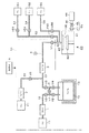
本発明の原料ガス供給装置を成膜装置に適用した構成例について説明する。図1に示すように成膜装置は、基板であるウエハ100に対してALD法による成膜処理を行なうための成膜処理部40を備え、この成膜処理部40に原料ガスを供給するため原料ガス供給装置で構成された原料ガス供給部10を備えている。なお明細書中においては、キャリアガスと、キャリアガスと共に流れる(昇華した)原料と、を併せたガスを原料ガスとする。
A configuration example in which the raw material gas supply apparatus of the present invention is applied to a film forming apparatus will be described. As shown in FIG. 1, the film forming apparatus includes a film forming
原料ガス供給部10は、液体又は固体原料、例えば固体原料のWCl6を収容した原料容器14を備えている。原料容器14は、常温では固体のWCl6を収容した容器であり、抵抗発熱体を備えたジャケット状の加熱部13により覆われている。この原料容器14は、図示しない温度検出部にて検出した原料容器14内の気相部の温度に基づいて、図示しない給電部から供給される給電量を増減することにより、原料容器14内の温度を調節できるように構成されている。加熱部13の設定温度は、固体原料が昇華し、且つWCl6が分解しない範囲の温度、例えば160℃に設定される。
The source
原料容器14内における固体原料の上方側の気相部には、例えばキャリアガス供給路12の下流端部と、原料ガス供給路32の上流端部と、が挿入されている。キャリアガス供給路12の上流端には、キャリアガス、例えばN2ガスの供給源であるキャリアガス供給源11が設けられ、キャリアガス供給路12には、上流側から第1のマスフローコントローラ(MFC)1、バルブV3、バルブV2がこの順序で介設されている。
For example, a downstream end portion of the carrier
一方、原料ガス供給路32には、上流側からバルブV4、バルブV5、流量測定部であるマスフローメータ(MFM)3及びバルブV1が設けられている。図中8は原料ガス供給路32から供給されるガスの圧力を測定するための圧力計である。原料ガス供給路32の下流端付近は、後述の反応ガスや置換ガスも流れることから、ガス供給路45として表示している。また原料ガス供給路32におけるMFM3の上流側には、希釈ガスを供給する希釈ガス供給路22の下流側端部が合流している。希釈ガス供給路22の上流側端部には、希釈ガス、例えばN2ガスの供給源である希釈ガス供給源21が設けられている。希釈ガス供給路22には、上流側から第2のマスフローコントローラ(MFC)2と、バルブV6と、が介設されている。キャリアガス供給路12におけるバルブV2とバルブV3との間と、原料ガス供給路32におけるバルブV4とバルブV5との間と、は、バルブV7を備えたバイパス流路7にて接続されている。バルブV2、V4及びV7は、切り替え機構に相当する。キャリアガス供給路12、原料ガス供給路32及びバイパス流路7及びバルブV2〜5、V7は、例えば抵抗発熱体を備えたジャケット状のマントルヒータで覆われている。
On the other hand, the raw material
続いて成膜処理部40について説明する。成膜処理部40は、例えば真空容器41内に、ウエハ100を水平保持すると共に、不図示のヒータを備えた載置台42と、原料ガス等を真空容器41内に導入するガス導入部43と、を備えている。ガス導入部43には、ガス供給路45が接続され、原料ガス供給部10から供給されるガスが、ガス導入部を介して、真空容器41内に供給されるように構成されている。更に真空容器41には、排気管46を介して、真空排気部44が接続されている。排気管46には、成膜処理部40内の圧力を調整する圧力調整部94を構成する圧力調整バルブ47と、バルブ48とが設けられている。
Next, the film
またガス供給路45には、原料ガスと反応する反応ガスを供給する反応ガス供給管50及び置換ガスを供給する置換ガス供給管56が合流されている。反応ガス供給管50の他端側は、反応ガス例えば水素(H2)ガスの供給源52に接続されたH2ガス供給管54と、不活性ガス例えば窒素(N2)ガスの供給源53に接続された不活性ガス供給管51とに分岐されている。また置換ガス供給管56の他端側は置換ガス、例えばN2ガスの供給源55に接続されている。図中のV50、V51、V54及びV56は、夫々反応ガス供給管50、不活性ガス供給管51、H2ガス供給管54及び置換ガス供給管56に設けられたバルブである。
In addition, a reaction
後述するように、成膜処理部40にて行なわれるW(タングステン)膜の成膜では、WCl6を含む原料ガスと、反応ガスであるH2ガスとが交互に繰り返して供給されると共に、これら原料ガス及び反応ガスの供給の間には、真空容器41内の雰囲気を置換するために置換ガスが供給される。このように原料ガスは、成膜処理部40に供給期間、休止期間を交互に繰り返して断続的に供給され、この原料ガスの供給制御はバルブV1をオン、オフ制御することにより実行される。このバルブV1は、後述する制御部9により開閉制御されるように構成されおり、「オン」とは、バルブV1を開いた状態、「オフ」とはバルブV1を閉じた状態である。
As will be described later, in the film formation of the W (tungsten) film performed in the film
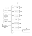
原料ガス供給部10には、制御部9が設けられている。図2に示すように制御部9は、CPU91、プログラム格納部92及びメモリ93を備えている。なお図中90はバスである。また制御部9は、各バルブ群V1〜V7、MFC1、MFC2、MFM3、及び成膜処理部40に接続された圧力調整部94に接続されている。また制御部9は上位コンピュータ99に接続されている。上位コンピュータ99からは、例えば成膜装置に搬入されるウエハ100のロットの成膜処理の処理レシピが送られて、メモリ93に記憶される。また制御部9には、ワークメモリ95が設けられ、原料容器14内の原料の残量が記憶される。また制御部9は、入力部97を備え、後述するように原料容器14の交換のときに例えばメーカーより伝えられる原料容器14内に充填された原料の充填量がワークメモリ95に書き込めるように構成されている。また制御部9には、アラーム発生部96が接続されている。更に制御部9は図示しないモニターなどの出力部に接続されており、ワークメモリ95に記臆されている原料の残量やアラームの発生の有無などがモニターに表示されるように構成されている。
The source
処理レシピは、各ロットごとに設定されたウエハ100の成膜処理の手順が処理条件と共に作成された情報である。処理条件としては、プロセス圧力、ALD法における成膜処理部40に供給されるガスの供給、休止のタイミング及び原料ガスの流量などが挙げられる。ALD法について簡単に説明すると、まず原料ガスであるWCl6ガスを例えば1秒間供給してバルブV1を閉じ、ウエハ100表面にWCl6を吸着させる。次いで置換ガス(N2ガス)を真空容器41に供給して、真空容器41内を置換する。続いて反応ガス(H2ガス)希釈ガス(N2ガス)と共に真空容器41に供給すると加水分解及び脱塩化反応によりW(タングステン)膜の原子膜がウエハ100の表面に形成される。この後、置換ガスを真空容器41に供給して、真空容器41を置換する。こうして真空容器41内に、WCl6を含む原料ガス→置換ガス→反応ガス→置換ガスを供給するサイクルを複数回繰り返すことにより、W膜の成膜を行う。
The processing recipe is information in which the film forming process procedure of the
ALD法は、原料ガス、置換ガス、反応ガス、置換ガスをこの順番で供給するサイクルを複数回実行するものであることから、このサイクルを規定したレシピにより、オン信号、オフ信号のタイミングが決定される。例えば原料ガスの給断はバルブV1により行われるためバルブV1のオン信号からオフ信号までの期間が原料ガスの供給時間であり、バルブV1のオフ信号からオン信号までの期間が、原料ガスの休止期間である。このようにMFC1、MFC2及びMFM3において原料の流量の測定値を求めるにあたって、ALD法を行う場合、原料ガスが間欠的に供給され、その供給時間が短いので、流量測定値が立ち上がって安定する前に立ち下がり、このため不安定になるおそれがある。このためMFC1、MFC2、MFM3の各測定値は、この例では後で詳述するようにバルブV1のオン、オフの1周期分の流量の測定値の積分値を1周期の時間で除算した値を測定出力値(指示値)として用いている(評価している)。 In the ALD method, the cycle of supplying the source gas, the replacement gas, the reaction gas, and the replacement gas in this order is executed a plurality of times, so the timing of the on signal and the off signal is determined by the recipe that defines this cycle. Is done. For example, since the supply / disconnection of the raw material gas is performed by the valve V1, the period from the on signal to the off signal of the valve V1 is the supply time of the raw material gas, and the period from the off signal of the valve V1 to the on signal is the rest of the raw material gas It is a period. Thus, when the ALD method is used to obtain the measured value of the raw material flow rate in the MFC1, MFC2, and MFM3, since the raw material gas is intermittently supplied and the supply time is short, before the flow rate measured value rises and stabilizes. And may become unstable. Therefore, the measured values of MFC1, MFC2, and MFM3 are values obtained by dividing the integrated value of the measured values of the flow rate for one cycle of on / off of the valve V1 by the time of one cycle, as will be described in detail later. Is used (evaluated) as a measured output value (indicated value).
プログラム格納部92に格納されているプログラムには、原料ガス供給部10の動作を実行するためのステップ群と、原料容器14内の残量を監視する動作を実行するためのステップ群と、が含まれている。なおプログラムという用語は、プロセスレシピなどのソフトウエアも含む意味として使用している。原料容器14内の残量を監視する動作を実行するためのステップ群の中には、MFC1、MFC2及びMFM3の各流量の測定出力を供給時間の間積分し、その積分値を供給期間の流量値として取り扱って演算するステップが含まれる。なお積分の演算処理については、時定数回路を用いたハード構成を用いてもよい。プログラムは、例えばハードディスク、コンパクトディスク、マグネットオプティカルディスク、メモリーカード等の記憶媒体に格納され、コンピュータにインストールされる。
The program stored in the
本発明の実施の形態の作用について図3に示すフローチャートを用いて説明する。今ステップS1に示すように原料容器14を原料が充填された新品の原料容器14に交換して、キャリアガス供給路12及び原料ガス供給路32に接続したものとすると、オペレータが当該原料容器14内の充填量(初期重量)を原料の残量の初期値R0として、入力部97を介して、メモリ93に記憶する(ステップS2)。新品の原料容器14の充填量は、例えば原料のメーカーから報告された値が用いられる。なお新品の原料容器14とは、原料の充填処理が行われた原料容器14を示し、原料が再充填された原料容器14を含む。
The operation of the embodiment of the present invention will be described with reference to the flowchart shown in FIG. As shown in step S1, if the
続いて先頭のロットのウエハ100が例えば25枚収められたキャリアがキャリアステージに運び込まれる。この場合ステップS3、ステップS4を介してステップS6に進み、先頭のロットの処理レシピの条件にてオフセット値が取得される。
Subsequently, a carrier containing, for example, 25
ここでオフセット値について説明する。図4は、原料ガス供給部10を用い、キャリアガス供給源11及び希釈ガス供給源21から夫々キャリアガス及び希釈ガスを供給し、MFM3を通過させた後、成膜処理部40にガスを供給したときのMFM3の測定値m3から、MFC1の測定値m1とMFC2の測定値m2との合計値を差し引いた値を示す。時刻t0からt100までは、キャリアガスを原料容器14を通過させずにバイパス流路7を介して、原料ガス供給路32に供給したときの(m3−(m1+m2))の値を示す。
Here, the offset value will be described. In FIG. 4, the source
時刻t0からt100の間は、MFM3を通過するガスは、キャリアガス供給路12から供給されるキャリアガスと、希釈ガス供給路22から供給される希釈ガスとを合わせたガスになる。しかしながらMFM3の測定値m3と、MFC1の測定値m1と、MFC2の測定値m2と、の合計値(m1+m2)と、差分は、図4に示すように0にならず誤差が生じる。この誤差分の値がオフセット値に相当する。この誤差分は、MFM3と、MFC1及びMFC2との各機器の個体誤差により生じる。
From time t 0 to t 100 , the gas passing through the
続いてオフセット値を取得する工程について説明する。オフセット値を求める作業は、MFC1及びMFC2の設定値を、処理レシピに書き込まれている、原料ガスの流量の目標値に応じて、決められたキャリアガスの流量値及び希釈ガスの流量値に設定して行われる。更に処理レシピにおける成膜処理部40に供給される原料ガスの供給、休止の周期におけるバルブV1の開閉のスケジュールと同じスケジュールにてバルブV1の開閉を行うように設定され、オフセット値を取得する工程における圧力は、処理レシピにより決められた圧力に設定されて作業が行われる。また成膜処理部40の温度調整には時間がかかることに加え気化した原料が低温の部位に付着し固化する可能性がある。従って成膜処理部40の温度は、例えば予め成膜処理における温度である170℃に設定されている。
Next, the process for acquiring the offset value will be described. The work to obtain the offset value is to set the set values of MFC1 and MFC2 to the carrier gas flow rate value and dilution gas flow rate value determined according to the target value of the raw material gas flow rate written in the processing recipe. Done. Further, a process of acquiring the offset value, which is set to open and close the valve V1 according to the same schedule as the opening and closing schedule of the supply of the source gas supplied to the film
このMFC1の設定値は、例えば原料が未使用の新品の原料容器14の状態において、目標値の流量の原料を供給することができるキャリアガスの流量に基づいて決定され、原料の流量の増減量とキャリアガスの流量の増減量との関係は、例えばメモリ93に記憶されている。また圧力調整部94により、成膜処理部40の圧力が処理レシピにおける設定圧力に設定される。
The set value of the
希釈ガスの流量の設定については、原料の流量が小さいため、例えば希釈ガスにより希釈された原料ガスの総流量をキャリアガス及び希釈ガスの合計流量として決めている場合には、総流量からキャリアガスの流量設定値を差し引いた値として決められる。また原料の流量も総流量に含める場合には、原料の供給量の目標値は、例えば単位時間当たりの重量として取り扱われることから、プロセス圧力と原料の供給量の目標値とに基づいて、総流量と原料を供給するためのキャリアガスの流量が求まる。従って、総流量から原料の供給量と、キャリアガスの流量と、の合計値を差し引いた値が希釈ガスの流量の設定値となる。 Regarding the setting of the flow rate of the dilution gas, since the flow rate of the raw material is small, for example, when the total flow rate of the source gas diluted with the dilution gas is determined as the total flow rate of the carrier gas and the dilution gas, the carrier gas is calculated from the total flow rate. It is determined as a value obtained by subtracting the flow rate setting value. In addition, when the raw material flow rate is included in the total flow rate, the target value of the raw material supply amount is handled as, for example, the weight per unit time, and therefore, based on the process pressure and the target value of the raw material supply amount, The flow rate and the flow rate of the carrier gas for supplying the raw material are obtained. Therefore, a value obtained by subtracting the total value of the supply amount of the raw material and the flow rate of the carrier gas from the total flow rate becomes the set value of the flow rate of the dilution gas.
次いでバルブV3、V5、V6、V7を開き、時刻t0以降にて、処理レシピにおけるバルブV1の開閉のタイミングと同じ周期でバルブV1の開閉を行う。ここでは、例えば時刻t0から時刻t100までの間にバルブV1を1秒間開き、1秒間閉じる動作を100回くり返す。なお真空容器41内は、既に真空排気されている。これにより、キャリアガス供給源11から、キャリアガスがMFC1の設定値に対応する流量でキャリアガス供給路12、バイパス流路7の順に流れて、原料ガス供給路32を流れる。その後原料ガス供給路32において、希釈ガス供給路22から供給される希釈ガスと混合されてMFM3を流れ、こうしてキャリアガスと希釈ガスとの混合ガスが成膜処理部40に間欠的に流れ込む。
Then opening the valve V3, V5, V6, V7, at time t 0 after, to open and close the valve V1 in the same cycle as the timing of the opening and closing of the valve V1 in the process recipe. Here, for example, the valve V1 during the period from the time t 0 to time t 100 to open 1 sec, repeated 100 times to close one second operation. Note that the
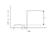
そしてt0〜t100におけるMFC1、MFC2及びMFM3の各々における流量の測定値を求める。図5(a)は、原料ガスの給断を行うバルブV1の状態を示しており、オンの時間帯が原料ガスの供給期間に相当し、オフの時間帯が原料ガスの休止期間に相当する。図5(b)は、時刻t0〜t100の間において、MFM3にて計測される原料ガスの流量の測定出力(指示値)の推移を示す。このようにバルブV1を開いている時間が短いため、MFM3にて計測される原料ガスの流量の測定出力はバルブV1のオン指令の後、急激に立ち上がり、バルブV1のオフ指令の後直ぐに立ち下がるパターンとなる。なお図5(a)における供給期間と休止期間との比率は便宜上のものである。
And determining the flow rate measurement of the respective t 0 ~t 100 in MFC1, MFC2 and MFM3. FIG. 5 (a) shows the state of the valve V1 that performs the supply and disconnection of the source gas. The ON time zone corresponds to the source gas supply period, and the OFF time zone corresponds to the source gas pause period. . FIG. 5B shows the transition of the measurement output (indicated value) of the flow rate of the raw material gas measured by the
そのためMFM3、MFC1及びMFC2の各流量測定出力を制御部9により各々原料ガスの供給、休止の1周期の間積分し、その積分値を1周期の時間Tで割った値を流量の測定値とする。ここでは、図5(a)に示すバルブV1のオン指令に基づいて、例えば時刻t0にガスの流量の積分動作を開始し、次のバルブV1のオン指令が出力される時刻t1に当該積分動作が終了する。このt0からt1までを1周期とする。
Therefore, the flow rate measurement outputs of MFM3, MFC1, and MFC2 are integrated by the
そしてMFC1、MFC2及びMFM3の各々においてt0からt1までの流量を積分した積分値を1周期の時間T、即ち時刻t0からt1までの時間(t1−t0)で割った値(積分値/(t1−t0))を夫々時刻t0からt1におけるMFC1の測定値m1、MFC2の測定値m2及びMFMの測定値m3とする。
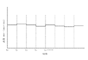
このようにt0からt1、t1からt2…の各周期において、m1、m2及びm3の各値を求め、図6に示すように各周期における(m3−(m1+m2))の値を求める。そして例えばt0から100周期分の(m3−(m1+m2))の値の平均値をオフセット値とする。
Then MFC1, MFC2 and an integrated value of the flow rate obtained by integrating from t 0 to t 1 1 period of time in each T of MFM3, i.e. from time t 0 to t 1 time (t 1 -t 0) divided by the value and (integrated value / (
Thus, in t 2 ... each period from t 0 from t 1, t 1, obtains the values of m1, m2 and m3, in each cycle as shown in FIG. 6 the value of (m3- (m1 + m2)) Ask. The example t 0 from 100 cycles of the average value of (m3- (m1 + m2)) and the offset value.
図3に戻ってステップS6にてオフセット値を取得した後、当該オフセット値が許容範囲内である場合には、ステップS7にて「YES」となり、ステップS8に進み、N=1に設定される。続いてステップS9においては、成膜処理部40にウエハ100を搬入し、1枚目のウエハ100の処理を開始する。
Returning to FIG. 3, after the offset value is acquired in step S6, if the offset value is within the allowable range, “YES” is determined in step S7, the process proceeds to step S8, and N = 1 is set. . Subsequently, in step S <b> 9, the
またステップS7にてオフセット値が許容範囲内にあるかを判断しているが、上述のようにオフセット値は、機器間の測定出力の差により生じる誤差を示す。そのためオフセット値があまりにも大きいときには、MFM3と、MFC1及びMFC2と、の個体誤差以外の要因による誤差が生じている可能性がある。従ってオフセット値を取得したときに、オフセット値が許容範囲内から外れてしまった場合には、ステップS7にて「NO」となり、ステップS15に進みアラーム発生部96により、アラームを鳴らした後、終了しメンテナンスを行う。
In step S7, it is determined whether the offset value is within the allowable range. As described above, the offset value indicates an error caused by a difference in measurement output between devices. Therefore, when the offset value is too large, there is a possibility that an error due to a factor other than the individual error between MFM3 and MFC1 and MFC2 may occur. Therefore, when obtaining the offset value, if the offset value is come off from the permissible range, "NO" in step S7, the
予め原料容器14の加熱部13はオンにされており、原料容器14が例えば160℃に加熱され、固体原料が昇華され、原料容器14内の原料の濃度が飽和濃度に近い濃度まで高められている。そして成膜処理部40にウエハ100を搬入し、処理レシピに基づいてウエハ100の処理を行い、後述の原料の流量の実測値mを取得する。即ち処理レシピに書き込まれているキャリアガスの流量値及び希釈ガスの流量値に設定し、さらに成膜処理部40の圧力を処理レシピにより決められた圧力に設定して、時刻taにおいて、バルブV7を閉じバルブV2及びV4を開く。これによりキャリアガス供給路12から原料容器14にMFC1により設定された流量でキャリアガスが供給され、原料容器14内において気化した原料がキャリアガスと共に原料ガス供給路32に流れる。更に希釈ガス供給路22から原料ガス供給路32に流れ込む希釈ガスが合流する。そして時刻taから処理レシピにおけるバルブV1の開閉の周期で、バルブV1の開閉を行う。ここではバルブV1を1秒間開き、1秒間閉じる動作をくり返す。これにより希釈ガスと混合された原料ガスが成膜処理部40に送られる。従ってキャリアガスの流量値及び希釈ガスの流量値、成膜処理部40の圧力、バルブV1の開閉の周期をオフセット値を取得する工程と同じ設定値として、キャリアガスを原料容器14に供給して、原料ガスを成膜処理部40に供給することになる。
この結果図5(c)に示すように原料ガスは、バルブV1のオン指令の後、急激に立ち上がり、時刻t0からt100までにおける測定値より大きな値まで上昇し、バルブV1のオフ指令の後直ぐに立ち下がるパターンとなる。
The
Material gas As a result, as shown in FIG. 5 (c), after the ON command of the valve V1, rising rapidly, rising from time t 0 to a value greater than the measured value at up to t 100, the OFF command of the valve V1 It becomes a pattern that falls immediately afterwards.
そして1枚目のウエハ100の処理において、時刻t0からt100までと同様にMFC1、MFC2及びMFM3の各々においてtaからta+1までの流量を積分した積分値を1周期の時間T、即ち時刻taからta+1までの時間(ta+1−ta)で割った値(積分値/(ta+1−ta))を算出し、夫々時刻taからta+1におけるMFC1の測定値m1、MFC2の測定値m2及びMFMの測定値m3とする。さらにガスの供給周期の1周期ごとにMFM3の測定値m3からMFC1の測定値m1とMFC2の測定値m2との合計値を差し引き、各周期の(m3−(m1+m2))の値を求める。時刻ta以降における各周期の(m3−(m1+m2))の値は、図4に示すように希釈ガスにより希釈され、成膜処理部40に供給される原料ガスの総流量からキャリアガスの流量と、希釈ガスの流量の合計値を差し引いた値、即ち原料の流量になるはずである。
And in the processing of the
しかしながら前述のように、MFM3の測定値と、MFC1の測定値m1とMFC2の測定値m2との合計値との間に、MFM3と、MFC1及びMFC2との機器間の測定出力の差により生じる誤差が含まれている。この誤差分に相当する値が上述したオフセット値であるため、図4及び図5(c)中に示す時刻ta以降における原料ガス供給の各周期の(m3−(m1+m2))の値の平均値を求め、時刻t0からt100におけるオフセット値を差し引くことにより、成膜処理部40に供給される原料の流量の実測値m(実流量)が求まる。実測値mは、下記の(1)式により原料(mg/分)の値に変換される。
原料(mg/分)=原料の流量(sccm)×0.2(Conversion Factor)/22400×原料の分子量(WCl6:396.6)×1000・・・(1)
ここでは、原料ガスの供給、休止の一周期の流量の積算値を平均化して原料の流量としている。従って原料の供給時間は、例えば1枚目のウエハ100の処理において、最初にバルブV1を開く時刻taから1枚目のウエハの処理を終え、バルブV1を閉じるまでの時間なる。この原料の供給時間を原料の流量の実測値mを(1)式により変換した値に乗算することにより、原料容器14から供給された原料の重量の実測値Mが算出される。
However, as described above, the error caused by the difference in the measured output between the devices of MFM3 and MFC1 and MFC2 between the measured value of MFM3 and the total value of measured value m1 of MFC1 and measured value m2 of MFC2. It is included. This average for a value corresponding to the error component is the offset value described above, the value of each cycle of the raw material gas supply in after time t a shown in FIG. 4 and FIG. 5 (c) (m3- (m1 + m2)) The actual value m (actual flow rate) of the flow rate of the raw material supplied to the
Raw material (mg / min) = raw material flow rate (sccm) × 0.2 (Conversion Factor) / 22400 × raw material molecular weight (WCl 6 : 396.6) × 1000 (1)
Here, the integrated value of the flow rate of the supply and stop of the raw material gas is averaged to obtain the raw material flow rate. Thus the raw material supply time, for example in the processing of the
次いでステップS10にて、1枚目のウエハ100を処理する前の原料の残量から原料の消費量である原料の重量の実測値Mを差し引く。これにより、1枚目のウエハ100の処理を終えた後の原料容器14内の原料の残量が求まる。この例では、新品の原料容器14をセットした後、初めて行われる成膜処理であることから、1枚目のウエハ100を処理する前の原料の残量は、既述の初期重量R0である。続いてステップS11においては、原料容器14内の原料の残量が第1の閾値以上の量であるか否かが判定される。第1の閾値は、例えば続く1枚のウエハ100の成膜処理を行った時にウエハ100の処理の間に原料容器14内の原料が空にならない値に設定される。従って予め1枚のウエハ100の処理に必要な量の原料の重量を測定し、当該原料の重量にマージンとなる量の原料の量を加算した量を算出し、マージンを含めた原料の量に相当する値を第1の閾値として設定する。
Next, in step S10, the actual measured value M of the raw material weight, which is the amount of the raw material consumed, is subtracted from the remaining amount of the raw material before processing the
原料容器14内の原料の残量が第1の閾値以上である場合には、ステップS12に進み、1枚目のウエハ100は、最終ウエハ100でないので「NO」となり、ステップS14にて、N=2に設定して、ステップS9に戻る。そしてステップS9にて、2枚目のウエハ100の成膜処理を行い、原料の流量の実測値mを取得し、原料容器14から供給された、即ち原料の重量の実測値Mを取得する。そしてステップS10にて、2枚目のウエハ100の成膜処理を終える前の原料容器14内の原料の残量から、当該ウエハ100の成膜処理により消費した原料の重量(実測値M)を差し引いて、当該ウエハの成膜処理を終えた後の原料容器14内の原料の残量が算出される。
If the remaining amount of the raw material in the
このようにステップS9からステップS12及びステップS14の工程を繰りかえし、ロットの全ウエハ100に対して順次の処理が行われ、各ウエハ100の成膜処理毎に原料容器14内の初期重量R0からウエハ100の成膜処理により消費された原料の累積消費量(累積使用量)を差し引いて原料容器14内の原料の残量を算出している。そして最後のウエハ100、ここでは25枚目のウエハ100においては、ステップS12において「YES」となりステップS13に進む。
In this way, the processes from step S9 to step S12 and step S14 are repeated, and all the
またロットのウエハ100の処理を行っているときに原料容器14内の原料の残量が第1の閾値を下回った場合には、ステップS11にて「NO」となりステップS15に進み、アラーム発生部96により、アラームを発した後、終了する。上述のように第1の閾値は、1枚のウエハ100の処理に必要な量の原料の重量にマージンとなる量の原料の量を加算した量に基づいて算出されている。そのため第1の閾値を下回ったときに原料容器14の交換を行うこととし、第1の閾値を下回っていない状態にて成膜処理を行うことにより、次のウエハ100の処理中における原料の枯渇を防ぐことができる。
If the remaining amount of the raw material in the
最終のウエハ100の成膜処理が終了して、当該ロットの処理が終了した後、ステップS13にて、原料容器14内の原料の残量が第2の閾値以上か否かが判断される。第2の閾値は、例えば1のロットの最大枚数(25枚)のウエハ100の処理を行うことができる原料の残量に設定される。従って1枚のウエハ100の処理に必要な原料の重量にウエハ100の最大枚数を乗算し、その乗算値にマージンを乗せた値を第2の閾値として設定する。
After the film formation process of the
原料の残量が第2の閾値以上である時には、続いてステップS3に戻り、後続のロットがキャリアステージに搬入されると、ステップS3を介してステップS4に進む。現在のロットは先頭のロットではないためステップS4において「NO」となり、ステップS5に進む。そしてステップS5において後続のロットのウエハ100に対する処理レシピが先のロット(1つ前のロット)における処理レシピと異なるかが判定される。具体的には、例えば処理レシピにおける原料の流量(原料の流量の目標値)、成膜処理部40の設定圧力及び成膜処理における原料ガスの供給、休止の周期の3つの項目が同一か否かが判定され、少なくとも一つの項目が異なる場合には、「YES」となり、ステップS6に進む。そしてステップS6において、現在のロット(当該後続のロット)のウエハ100に対する処理レシピに基づいて、原料の流量の目標値、成膜処理部40の設定圧力及び成膜処理における原料ガスの供給、休止の周期が設定される。そして、先のロットと同様にオフセット値が取得され、続くステップS7以降の工程を行う。
When the remaining amount of the raw material is equal to or greater than the second threshold value, the process returns to step S3. When the subsequent lot is loaded on the carrier stage, the process proceeds to step S4 via step S3. Since the current lot is not the first lot, “NO” is determined in the step S4, and the process proceeds to the step S5. In step S5, it is determined whether the processing recipe for the
また後続のロットにおける処理レシピが先のロットの(1つ前のロット)における処理レシピ、具体的には、例えば処理レシピにおける原料の流量(原料の流量の目標値)、成膜処理部40の設定圧力及び成膜処理における原料ガスの供給、休止の周期の3つの項目が同一である場合には、ステップS5にて「NO」となり、ステップS8に進み、先のロットで用いたオフセット値を用いて、続くステップS8以降の工程を行う。
後続のロットの処理においては、メモリ93に直前のロットにおける最後のウエハ100の処理を行った後の原料の残量が記憶されている。そのためステップS8に進み、N=1と設定した後、ステップS9以降の処理は、直前のロットにおける最後のウエハ100の処理を行った後の原料の残量から、順次1枚当たりのウエハ100における原料の消費量を差し引いて、残量の算出が行われる。
Further, the processing recipe in the subsequent lot is the processing recipe in the previous lot (the previous lot), specifically, for example, the raw material flow rate (target value of the raw material flow rate) in the processing recipe, If the three items of the set pressure, the supply of the source gas in the film forming process, and the period of pause are the same, “NO” is determined in the step S5, the process proceeds to a step S8, and the offset value used in the previous lot is set. Then, the subsequent steps after step S8 are performed.
In the subsequent lot processing, the memory 93 stores the remaining amount of raw material after processing the
さらに各ロットの最終ウエハ100の処理を行った後、原料容器14内の原料の残量が第2の閾値を下回った場合には、ステップS13にて「NO」となりステップS15に進みアラーム発生部96によりアラームを発した後、終了する。第2の閾値は、1ロットの最大枚数のウエハ100の処理に必要な量の原料の重量にマージンとなる量の原料の量を加算した量に基づいて算出されている。そのため第2の閾値を下回わったときに装置を停止して原料容器14の交換を行うように設定し、第2の閾値を下回っていない状態にて成膜処理を行うことにより、次のロットの処理中における原料の枯渇を防ぐことができる。
Further, after the processing of the
また第2の閾値以上であれば、次のロットのウエハ100の成膜処理ができるはずであるが、ステップS11において、第1の閾値を以上の原料が残っているかを確認することで、何らかの装置の不具合の発生により、ロットのすべてのウエハ100の処理を終える前に、原料が枯渇した場合であっても、より確実にウエハ100の処理中の原料の枯渇を防ぐことができる。
If it is equal to or greater than the second threshold value, it should be possible to form a film on the
また例えば成膜装置において真空容器41内のクリーニング処理の後に、真空容器41に成膜ガスを供給して、成膜処理部41の内壁に成膜の対象となっている薄膜を形成し、真空容器41のコンディションの状態を整えるプリコートを行う場合がある。この場合はプリコートを行うために成膜処理部40に供給された原料の重量の実測値Mを同様に求め、原料の初期重量R0から差し引かれる原料の重量の実測値Mの累積値の中にプリコート時の原料の消費量が加わることになる。
さらに1枚目のウエハ100の処理の前にウエハ100を搬入していない成膜処理部400に原料を供給して行うダミー処理を行う場合においては、同様に成膜処理部40に供給された原料の重量の実測値Mを求め、原料の初期重量R0から差し引かれる原料の重量の実測値Mの累積値の中にダミー処理時の原料の消費量が加わることになる。
Further, for example, after the cleaning process in the
Further, in the case where dummy processing is performed by supplying a raw material to the film formation processing unit 400 that has not carried the
上述の実施形態では、キャリアガスを原料容器14に供給して、気化した原料をキャリアガスと共に原料容器14から流出させ、更に希釈ガスで希釈した後、成膜処理部40に供給するにあたり、気化した原料、キャリアガス及び希釈ガスの各流量の合計の測定値からキャリアガス及び希釈ガスの各流量の測定値の合計を差し引いた差分値に対して、更に各測定機器の個体間の誤差に基づくオフセット値を差し引いて、原料の流量の実測値として取り扱っている。そして原料の流量の実測値と、原料の供給時間とから供給された原料の重量の実測値を求め、原料容器14に収容されていた原料の量から原料の重量の実測値Mを差し引いて、原料容器14内の原料の残量を求めている。従って各測定機器の個体間の誤差分が相殺され、原料の残量を正確に求めることができる。
In the above-described embodiment, the carrier gas is supplied to the
さらにALD法を実施するにあたり、各測定機器において原料ガスの供給、休止の1周期における測定出力の積分値を流量測定値として取り扱っているため、短時間でのガスの流量の立ち上がり、立ち下りに起因する測定の不安定性を避けることができ、ガス流量の測定値を安定して求めることができる。 Furthermore, when carrying out the ALD method, each measuring instrument handles the integrated value of the measured output during one cycle of supply and pause of the raw material gas as the flow rate measurement value, so that the gas flow rate rises and falls in a short time. The resulting measurement instability can be avoided, and the measured value of the gas flow rate can be obtained stably.
さらに流量測定値を算出するにあたって、MFM3、MFC1及びMFC2の各流量測定出力を制御部9により各々原料ガスの供給、休止の周期n(2以上)の周期の間積分し、その積分値をn周期の時間nTで割った値を流量の測定値m1、m2及びm3としてもよい。
Further, in calculating the flow rate measurement value, the flow rate measurement outputs of MFM3, MFC1 and MFC2 are integrated by the
またステップS9にて取得した原料の流量を用いて、原料の流量と原料の目標値とに誤差が生じているときには、キャリアガスの流量を調整して、原料の供給量を調整するようにしてもよく、さらに原料の流量と原料の目標値との誤差が大きいときには、アラームを鳴らして終了するようにしてもよい。ステップS9にて取得している原料の流量は、オフセット値を差し引いている。そのため各測定機器の個体間の誤差分が相殺され、原料の量の正確な実測値を求めることができ、実測値に基づいてキャリアガスの供給量を調整することで、ウエハ100毎の原料の供給量を安定させることができる。
Further, when there is an error between the raw material flow rate and the raw material target value using the raw material flow rate obtained in step S9, the carrier gas flow rate is adjusted to adjust the raw material supply amount. Alternatively, when the error between the raw material flow rate and the raw material target value is large, an alarm may be sounded to end the processing. The flow rate of the raw material acquired in step S9 is obtained by subtracting the offset value. Therefore, the error between the individual measuring devices is offset, and an accurate actual measurement value of the raw material amount can be obtained. By adjusting the supply amount of the carrier gas based on the actual measurement value, the raw material amount for each
また例えばウエハ100をALD法により処理するにあたって、原料の給断を100サイクル行い成膜処理を行うとして、前半の50サイクルにおける原料の流量及び原料ガスの供給時間と、前半の50サイクルにおける原料の流量及び原料ガスの供給時間と、が異なる処理レシピを用いる場合がある。その場合には、ステップS6のオフセット値を取得する工程において、前半の50サイクルにおける前半のオフセット値と、後半の50サイクルにおける後半のオフセット値とを取得する。
Further, for example, when processing the
そしてステップS9において、原料容器14から供給された原料の重量の実測値Mを取得するときに、各ウエハ100の成膜処理において、前半の50サイクルにおける成膜処理においては、前半のオフセット値を用いて、前半の原料の流量の実測値mを求める。そして、前半の50サイクルにおける原料の供給時間を乗算することにより、前半の50サイクルおける原料の重量の実測値M1を取得する。次いで後半の50サイクルにおける成膜処理においては、後半のオフセット値を用いて、後半の50サイクルおける原料の重量の実測値M2を取得する。そして前半の50サイクルおける原料の重量の実測値M1と後半の50サイクルおける原料の重量の実測値M2を加算することにより原料容器14から供給された原料の重量の実測値Mとすればよい。
In step S9, when the measured value M of the weight of the raw material supplied from the
本発明はCVD法により成膜処理を行う成膜装置に用いてもよい。CVD法においては原料ガスを成膜処理部40に連続的に供給すると共に、反応ガスを供給してウエハ100に成膜を行う。CVD法においては、原料ガスの流量が安定した状態におけるMFM3、MFC1及びMFC2の各流量測定出力を夫々MFM3、MFC1及びMFC2の測定値m1、m2及びm3としてもよい。
The present invention may be used in a film forming apparatus that performs a film forming process by a CVD method. In the CVD method, a raw material gas is continuously supplied to the film
1 MFM
2、3 MFC
7 バイパス流路
9 制御部
12 キャリアガス供給路
14 原料容器
22 希釈ガス供給路
32 ガス供給路
40 真空処理部
44 真空排気部
47 圧力調整バルブ
48 バルブ
100 ウエハ
V1〜V7 バルブ
1 MFM
2, 3 MFC
7
Claims (9)
前記原料容器にキャリアガスを供給するためのキャリアガス供給路と、
前記キャリアガス供給路から分岐し、前記原料容器を迂回して原料ガス供給路に接続されたバイパス流路と、
前記原料ガス供給路における前記バイパス流路の接続部位よりも下流側に接続され、希釈ガスを原料ガスに合流させるための希釈ガス供給路と、
前記キャリアガス供給路及び前記希釈ガス供給路に夫々接続された第1のマスフローコントローラ及び第2のマスフローコントローラと、
前記原料ガス供給路における希釈ガス供給路の合流部位の下流側に設けられたマスフローメータと、
前記キャリアガス供給路から原料ガス供給路に至るキャリアガス流路を、前記原料容器内とバイパス流路との間で切り替える切替え機構と、
前記キャリアガス流路を前記原料容器内に切り替えた状態で、原料ガスをキャリアガス及び希釈ガスと共に前記成膜処理部内の基板に供給する原料供給ステップと、新品の原料容器内の原料の充填量から、前記原料供給ステップ時における原料ガスの実流量に基づいて計算される原料の消費量を含む累積消費量を差し引いて原料容器の残量を求める残量算出ステップと、を実行する制御部とを備え、
前記原料ガスの実流量は、前記第1のマスフローコントローラ、第2のマスフローコントローラ及びマスフローメータの流量の各測定値を夫々m1、m2及びm3とすると、前記キャリアガス流路をバイパス流路側に切り替えた状態で、キャリアガス及び希釈ガスを流して{m3−(m1+m2)}の演算値であるオフセット値を求める第1のステップと、前記キャリアガス流路を原料容器側に切り替えた状態で、キャリアガス及び希釈ガスを流して{m3−(m1+m2)}の演算値を求め、この演算値から前記オフセット値を差し引いて原料の流量の実測値を求める第2のステップと、により求められることを特徴とする原料ガス供給装置。 In a raw material gas supply apparatus that vaporizes a solid or liquid raw material in a raw material container and supplies the substrate as a raw material gas together with a carrier gas to a film formation processing unit that forms a substrate through a raw material gas supply path.
A carrier gas supply path for supplying a carrier gas to the raw material container;
A bypass flow path branched from the carrier gas supply path and bypassing the raw material container and connected to the raw material gas supply path;
A dilution gas supply path that is connected to the downstream side of the connection portion of the bypass flow path in the source gas supply path, and for joining the dilution gas to the source gas,
A first mass flow controller and a second mass flow controller respectively connected to the carrier gas supply path and the dilution gas supply path;
A mass flow meter provided on the downstream side of the confluence portion of the dilution gas supply path in the source gas supply path;
A switching mechanism for switching the carrier gas flow path from the carrier gas supply path to the raw material gas supply path between the raw material container and the bypass flow path;
A raw material supply step for supplying the raw material gas together with the carrier gas and the dilution gas to the substrate in the film forming unit while the carrier gas flow path is switched into the raw material container, and a filling amount of the raw material in the new raw material container A remaining amount calculating step for calculating a remaining amount of the raw material container by subtracting a cumulative consumption amount including a raw material consumption amount calculated based on an actual flow rate of the raw material gas at the time of the raw material supply step; With
The actual flow rate of the source gas is switched to the bypass flow channel side when the measured values of the flow rates of the first mass flow controller, the second mass flow controller and the mass flow meter are m1, m2 and m3, respectively. In a state where the carrier gas and the dilution gas are flown and the carrier gas channel and the diluent gas are flown, the carrier gas flow path is switched to the raw material container side in the first step for obtaining the offset value which is the calculated value of {m3- (m1 + m2)}. The calculated value of {m3− (m1 + m2)} is obtained by flowing a gas and a dilution gas, and the second step of calculating the actual value of the flow rate of the raw material by subtracting the offset value from the calculated value. Raw material gas supply device.
前記残量算出ステップにおける累積消費量は、ダミー供給ステップにおける原料ガスの実流量に基づいて計算される原料の消費量を含むことを特徴とする請求項1に記載の原料ガス供給装置。 The control unit executes a dummy supply step of supplying the carrier gas and the dilution gas to the film forming unit in a state where the carrier gas channel is switched to the raw material container side before the film forming process of the first substrate of the lot. And
2. The raw material gas supply apparatus according to claim 1, wherein the cumulative consumption amount in the remaining amount calculation step includes a raw material consumption amount calculated based on an actual flow rate of the raw material gas in the dummy supply step.
前記残量算出ステップにおける累積消費量は、プリコートステップにおける原料ガスの実流量に基づいて計算される原料の消費量を含むことを特徴とする請求項1または2に記載の原料ガス供給装置。 The control unit supplies the carrier gas and the dilution gas to the film forming unit in a state where the carrier gas channel is switched to the material container side before the film forming process of the substrate, and supplies the raw material to the inner surface of the film forming unit. Performing a pre-coating step to form a layer of a reaction product obtained by reacting the gas and the reaction gas;
The raw material gas supply apparatus according to claim 1, wherein the cumulative consumption amount in the remaining amount calculation step includes a raw material consumption amount calculated based on an actual flow rate of the raw material gas in the precoat step.
前記第2のステップにおける測定値m1、m2及びm3は、原料ガスの供給、休止の周期をTとすると、n(nは1以上の整数)周期における流量の積分値を周期Tで除算した値であることを特徴とする請求項1ないし3のいずれか一項に記載の原料ガス供給装置。 The film forming process performed in the film forming processing unit alternately supplies a source gas and a reaction gas that reacts with the source gas to the substrate, and a replacement gas is supplied between the source gas supply and the reaction gas supply. A film forming process performed by supplying a gas;
The measured values m1, m2, and m3 in the second step are values obtained by dividing the integral value of the flow rate in the period of n (n is an integer of 1 or more) by the period T, where T is the period of supplying and stopping the source gas. The raw material gas supply apparatus according to any one of claims 1 to 3, wherein
前記第1のステップにおける測定値m1、m2及びm3は、n周期における流量の積分値を周期Tで除算した値であることを特徴とする請求項4に記載の原料ガス供給装置。 Before processing the first substrate of a lot of substrates, the control unit reads the supply gas cycle and pause period T from the processing recipe of the lot,
5. The raw material gas supply apparatus according to claim 4, wherein the measured values m1, m2, and m3 in the first step are values obtained by dividing the integral value of the flow rate in the n period by the period T.
前記原料容器にキャリアガスを供給するためのキャリアガス供給路と、前記キャリアガス供給路から分岐し、前記原料容器を迂回して原料ガス供給路に接続されたバイパス流路と、前記原料ガス供給路における前記バイパス流路の接続部位よりも下流側に接続され、希釈ガスを原料ガスに合流させるための希釈ガス供給路と、前記キャリアガス供給路及び前記希釈ガス供給路に夫々接続された第1のマスフローコントローラ及び第2のマスフローコントローラと、前記原料ガス供給路における希釈ガス供給路の合流部位の下流側に設けられたマスフローメータと、前記キャリアガス供給路から原料ガス供給路に至るキャリアガス流路を、前記原料容器内とバイパス流路との間で切り替える切替え機構と、を備えた原料ガス供給装置を用い、
前記キャリアガス流路を原料容器側に切り替えた状態で、原料ガスをキャリアガス及び希釈ガスと共に前記成膜処理部内の基板に供給する工程と、
新品の原料容器内の原料の充填量から、原料を成膜処理部内の基板に供給したときの原料の実流量に基づいて計算される原料の消費量を含む累積消費量を差し引いて、原料容器の残量を求める工程と、を含み、
前記実流量は、前記第1のマスフローコントローラ、第2のマスフローコントローラ及びマスフローメータの流量の各測定値を夫々m1、m2及びm3とすると、前記キャリアガス流路をバイパス流路側に切り替えた状態で、キャリアガス及び希釈ガスを流して{m3−(m1+m2)}の演算値であるオフセット値を求める工程と、前記キャリアガス流路を原料容器側に切り替えた状態で、キャリアガス及び希釈ガスを流して{m3−(m1+m2)}の演算値を求め、この演算値から前記オフセット値を差し引いて原料の流量の実測値を求める工程と、により求められることを特徴とする原料ガス供給方法。 In a raw material gas supply method for vaporizing a solid or liquid raw material in a raw material container and supplying the substrate as a raw material gas together with a carrier gas through a raw material gas supply path to a film formation processing unit,
A carrier gas supply path for supplying a carrier gas to the source container; a bypass channel branched from the carrier gas supply path and bypassing the source container and connected to the source gas supply path; and the source gas supply Connected to the downstream side of the connection part of the bypass flow path in the channel, and connected to the dilution gas supply path for joining the dilution gas to the source gas, the carrier gas supply path and the dilution gas supply path, respectively. A first mass flow controller, a second mass flow controller, a mass flow meter provided on the downstream side of the confluence portion of the dilution gas supply path in the source gas supply path, and a carrier gas from the carrier gas supply path to the source gas supply path Using a source gas supply device comprising a switching mechanism for switching the flow path between the inside of the raw material container and the bypass flow path,
Supplying the source gas together with the carrier gas and the dilution gas to the substrate in the film forming unit in a state where the carrier gas channel is switched to the source container side;
Subtract the cumulative consumption amount including the consumption amount of the raw material calculated based on the actual flow rate of the raw material when the raw material is supplied to the substrate in the film forming unit from the filling amount of the raw material in the new raw material container. And a step of determining the remaining amount of
When the measured values of the flow rates of the first mass flow controller, the second mass flow controller, and the mass flow meter are m1, m2, and m3, respectively, the actual flow rate is in a state in which the carrier gas channel is switched to the bypass channel side. Then, the carrier gas and the dilution gas are flowed, and the carrier gas and the dilution gas are flowed in the state where the offset value which is the calculated value of {m3- (m1 + m2)} is obtained and the carrier gas flow path is switched to the raw material container side. And obtaining a calculated value of {m3- (m1 + m2)} and subtracting the offset value from the calculated value to obtain an actual measured value of the flow rate of the raw material.
前記キャリアガス流路を原料容器側に切り替えた状態で、キャリアガス及び希釈ガスを流して{m3−(m1+m2)}の演算値を求める工程における測定値m1、m2及びm3は、原料ガスの供給、休止の周期をTとすると、n(nは1以上の整数)周期における流量の積分値を周期Tで除算した値であることを特徴とする請求項6に記載の原料ガス供給方法。 The film forming process performed in the film forming processing unit alternately supplies a source gas and a reaction gas that reacts with the source gas to the substrate, and a replacement gas is supplied between the source gas supply and the reaction gas supply. A film forming process performed by supplying a gas;
The measured values m1, m2, and m3 in the step of obtaining the calculated value of {m3- (m1 + m2)} by flowing the carrier gas and the dilution gas while the carrier gas flow path is switched to the raw material container side are the supply of the raw material gas The raw material gas supply method according to claim 6, wherein an integral value of a flow rate in a cycle of n (n is an integer of 1 or more) is divided by a cycle T, where T is a pause cycle.
前記コンピュータプログラムは、請求項6ないし8のいずれか一項に記載の原料ガス供給方法を実行するようにステップ群が組まれていることを特徴とする記憶媒体。 A computer program used for a raw material gas supply apparatus that vaporizes a solid or liquid raw material in a raw material container and supplies the raw material gas together with a carrier gas as a raw material gas through a raw material gas supply path to a film forming processing unit A storage medium storing
A storage medium, wherein the computer program includes a set of steps so as to execute the raw material gas supply method according to any one of claims 6 to 8.
Priority Applications (6)
| Application Number | Priority Date | Filing Date | Title |
|---|---|---|---|
| JP2015235846A JP6565645B2 (en) | 2015-12-02 | 2015-12-02 | Raw material gas supply apparatus, raw material gas supply method and storage medium |
| TW105138271A TWI696723B (en) | 2015-12-02 | 2016-11-22 | Raw material gas supply device, raw material gas supply method and memory medium |
| US15/367,096 US10385457B2 (en) | 2015-12-02 | 2016-12-01 | Raw material gas supply apparatus, raw material gas supply method and storage medium |
| KR1020160162797A KR101988090B1 (en) | 2015-12-02 | 2016-12-01 | Raw material gas supply apparatus, raw material gas supply method and storage medium |
| CN201611095814.3A CN106987824B (en) | 2015-12-02 | 2016-12-02 | Raw material gas supply device and raw material gas supply method |
| KR1020190021214A KR20190022596A (en) | 2015-12-02 | 2019-02-22 | Raw material gas supply apparatus, raw material gas supply method and storage medium |
Applications Claiming Priority (1)
| Application Number | Priority Date | Filing Date | Title |
|---|---|---|---|
| JP2015235846A JP6565645B2 (en) | 2015-12-02 | 2015-12-02 | Raw material gas supply apparatus, raw material gas supply method and storage medium |
Publications (3)
| Publication Number | Publication Date |
|---|---|
| JP2017101295A JP2017101295A (en) | 2017-06-08 |
| JP2017101295A5 JP2017101295A5 (en) | 2018-12-13 |
| JP6565645B2 true JP6565645B2 (en) | 2019-08-28 |
Family
ID=58798924
Family Applications (1)
| Application Number | Title | Priority Date | Filing Date |
|---|---|---|---|
| JP2015235846A Active JP6565645B2 (en) | 2015-12-02 | 2015-12-02 | Raw material gas supply apparatus, raw material gas supply method and storage medium |
Country Status (5)
| Country | Link |
|---|---|
| US (1) | US10385457B2 (en) |
| JP (1) | JP6565645B2 (en) |
| KR (2) | KR101988090B1 (en) |
| CN (1) | CN106987824B (en) |
| TW (1) | TWI696723B (en) |
Families Citing this family (17)
| Publication number | Priority date | Publication date | Assignee | Title |
|---|---|---|---|---|
| DE102014115497A1 (en) * | 2014-10-24 | 2016-05-12 | Aixtron Se | Tempered gas supply with diluent gas streams fed in at several points |
| WO2018025713A1 (en) * | 2016-08-05 | 2018-02-08 | 株式会社堀場エステック | Gas control system and film formation device provided with gas control system |
| JP6904231B2 (en) * | 2017-12-13 | 2021-07-14 | 東京エレクトロン株式会社 | Substrate processing method, storage medium and raw material gas supply device |
| US11685998B2 (en) | 2018-06-21 | 2023-06-27 | Asm Ip Holding B.V. | Substrate processing apparatus, storage medium and substrate processing method |
| JP7094172B2 (en) | 2018-07-20 | 2022-07-01 | 東京エレクトロン株式会社 | Film forming equipment, raw material supply equipment and film forming method |
| TWI821363B (en) * | 2018-08-31 | 2023-11-11 | 美商應用材料股份有限公司 | Precursor delivery system |
| JP7281285B2 (en) | 2019-01-28 | 2023-05-25 | 株式会社堀場エステック | DENSITY CONTROLLER, ZERO POINT ADJUSTMENT METHOD, AND PROGRAM FOR DENSITY CONTROLLER |
| JP7356237B2 (en) | 2019-03-12 | 2023-10-04 | 株式会社堀場エステック | Concentration control device, raw material consumption estimation method, and program for concentration control device |
| CN112144038B (en) * | 2019-06-27 | 2023-06-27 | 张家港恩达通讯科技有限公司 | GaAs-based epitaxial doping source supply system for MOCVD equipment |
| JP2021042445A (en) * | 2019-09-12 | 2021-03-18 | 東京エレクトロン株式会社 | Control method of gas supply device, substrate processing device and gas supply device |
| TWI846960B (en) * | 2019-10-04 | 2024-07-01 | 法商液態空氣喬治斯克勞帝方法研究開發股份有限公司 | Supply system for low volatility precursors |
| JP7413120B2 (en) * | 2020-03-27 | 2024-01-15 | 東京エレクトロン株式会社 | Gas supply amount calculation method and semiconductor device manufacturing method |
| JP7635529B2 (en) * | 2020-09-30 | 2025-02-26 | 東京エレクトロン株式会社 | Method for estimating remaining amount of solid source material, method for forming film, device for supplying source gas, and device for forming film |
| US11735447B2 (en) * | 2020-10-20 | 2023-08-22 | Applied Materials, Inc. | Enhanced process and hardware architecture to detect and correct realtime product substrates |
| US12191214B2 (en) * | 2021-03-05 | 2025-01-07 | Taiwan Semiconductor Manufacturing Company Limited | System and methods for controlling an amount of primer in a primer application gas |
| US20230029724A1 (en) * | 2021-07-27 | 2023-02-02 | Asm Ip Holding B.V. | System and method for monitoring precursor delivery to a process chamber |
| JP7799242B2 (en) * | 2022-03-28 | 2026-01-15 | 株式会社島津製作所 | Gas analyzer and calibration gas supply method |
Family Cites Families (12)
| Publication number | Priority date | Publication date | Assignee | Title |
|---|---|---|---|---|
| JPH10147871A (en) * | 1996-11-15 | 1998-06-02 | Daido Steel Co Ltd | Vaporization equipment for vapor phase growth equipment |
| JP3973605B2 (en) * | 2002-07-10 | 2007-09-12 | 東京エレクトロン株式会社 | Film forming apparatus, raw material supply apparatus used therefor, and film forming method |
| US20050095859A1 (en) * | 2003-11-03 | 2005-05-05 | Applied Materials, Inc. | Precursor delivery system with rate control |
| JP2006222133A (en) * | 2005-02-08 | 2006-08-24 | Hitachi Cable Ltd | Raw material gas supply method and apparatus |
| US20080141937A1 (en) * | 2006-12-19 | 2008-06-19 | Tokyo Electron Limited | Method and system for controlling a vapor delivery system |
| JP5103983B2 (en) * | 2007-03-28 | 2012-12-19 | 東京エレクトロン株式会社 | Gas supply method, gas supply apparatus, semiconductor manufacturing apparatus, and storage medium |
| JP5703114B2 (en) | 2011-04-28 | 2015-04-15 | 株式会社フジキン | Raw material vaporizer |
| KR102245759B1 (en) * | 2011-07-22 | 2021-04-27 | 어플라이드 머티어리얼스, 인코포레이티드 | Reactant delivery system for ald/cvd processes |
| JP5895712B2 (en) * | 2012-05-31 | 2016-03-30 | 東京エレクトロン株式会社 | Source gas supply apparatus, film forming apparatus, source gas supply method, and storage medium |
| JP2014145115A (en) * | 2013-01-29 | 2014-08-14 | Tokyo Electron Ltd | Raw gas supply apparatus, film deposition apparatus, flow rate measuring method, and memory medium |
| JP6142629B2 (en) * | 2013-03-29 | 2017-06-07 | 東京エレクトロン株式会社 | Source gas supply apparatus, film forming apparatus, and source gas supply method |
| JP6135475B2 (en) * | 2013-11-20 | 2017-05-31 | 東京エレクトロン株式会社 | Gas supply apparatus, film forming apparatus, gas supply method, and storage medium |
-
2015
- 2015-12-02 JP JP2015235846A patent/JP6565645B2/en active Active
-
2016
- 2016-11-22 TW TW105138271A patent/TWI696723B/en active
- 2016-12-01 KR KR1020160162797A patent/KR101988090B1/en active Active
- 2016-12-01 US US15/367,096 patent/US10385457B2/en active Active
- 2016-12-02 CN CN201611095814.3A patent/CN106987824B/en active Active
-
2019
- 2019-02-22 KR KR1020190021214A patent/KR20190022596A/en not_active Withdrawn
Also Published As
| Publication number | Publication date |
|---|---|
| JP2017101295A (en) | 2017-06-08 |
| KR101988090B1 (en) | 2019-06-11 |
| KR20190022596A (en) | 2019-03-06 |
| US10385457B2 (en) | 2019-08-20 |
| US20170159175A1 (en) | 2017-06-08 |
| TWI696723B (en) | 2020-06-21 |
| KR20170065007A (en) | 2017-06-12 |
| CN106987824A (en) | 2017-07-28 |
| CN106987824B (en) | 2019-09-03 |
| TW201738406A (en) | 2017-11-01 |
Similar Documents
| Publication | Publication Date | Title |
|---|---|---|
| JP6565645B2 (en) | Raw material gas supply apparatus, raw material gas supply method and storage medium | |
| JP6627474B2 (en) | Source gas supply device, source gas supply method, and storage medium | |
| KR102109287B1 (en) | Method of processing substrate, storage medium, and raw material gas supply device | |
| US10113235B2 (en) | Source gas supply unit, film forming apparatus and source gas supply method | |
| US9725808B2 (en) | Raw material gas supply apparatus | |
| TWI557264B (en) | Raw material gas supply device, film formation device, raw material gas supply method, and non-transitory memory medium | |
| JP6678489B2 (en) | Substrate processing equipment | |
| US20170092549A1 (en) | Raw material gas supply apparatus, raw material gas supply method and storage medium | |
| JP2014145115A (en) | Raw gas supply apparatus, film deposition apparatus, flow rate measuring method, and memory medium | |
| KR20200001531A (en) | Method of manufacturing semiconductor device, method of managing parts, substrate processing apparatus and substrate processing program | |
| JP2017053039A (en) | Raw material gas supply apparatus, film deposition apparatus, method for measuring flow rate, and storage medium | |
| JP2016186126A (en) | Raw material supply apparatus, raw material supply method, and storage medium | |
| JP7635529B2 (en) | Method for estimating remaining amount of solid source material, method for forming film, device for supplying source gas, and device for forming film | |
| JP2026508997A (en) | Flow-over vapor precursor supply |
Legal Events
| Date | Code | Title | Description |
|---|---|---|---|
| RD02 | Notification of acceptance of power of attorney |
Free format text: JAPANESE INTERMEDIATE CODE: A7422 Effective date: 20180112 |
|
| A521 | Request for written amendment filed |
Free format text: JAPANESE INTERMEDIATE CODE: A523 Effective date: 20180921 |
|
| A621 | Written request for application examination |
Free format text: JAPANESE INTERMEDIATE CODE: A621 Effective date: 20180921 |
|
| A521 | Request for written amendment filed |
Free format text: JAPANESE INTERMEDIATE CODE: A523 Effective date: 20181030 |
|
| A977 | Report on retrieval |
Free format text: JAPANESE INTERMEDIATE CODE: A971007 Effective date: 20190531 |
|
| TRDD | Decision of grant or rejection written | ||
| A01 | Written decision to grant a patent or to grant a registration (utility model) |
Free format text: JAPANESE INTERMEDIATE CODE: A01 Effective date: 20190702 |
|
| A61 | First payment of annual fees (during grant procedure) |
Free format text: JAPANESE INTERMEDIATE CODE: A61 Effective date: 20190715 |
|
| R150 | Certificate of patent or registration of utility model |
Ref document number: 6565645 Country of ref document: JP Free format text: JAPANESE INTERMEDIATE CODE: R150 |
|
| R250 | Receipt of annual fees |
Free format text: JAPANESE INTERMEDIATE CODE: R250 |
|
| R250 | Receipt of annual fees |
Free format text: JAPANESE INTERMEDIATE CODE: R250 |
|
| R250 | Receipt of annual fees |
Free format text: JAPANESE INTERMEDIATE CODE: R250 |
|
| R250 | Receipt of annual fees |
Free format text: JAPANESE INTERMEDIATE CODE: R250 |