JP6564970B2 - Control of product dispenser energy storage device - Google Patents
Control of product dispenser energy storage device Download PDFInfo
- Publication number
- JP6564970B2 JP6564970B2 JP2016560957A JP2016560957A JP6564970B2 JP 6564970 B2 JP6564970 B2 JP 6564970B2 JP 2016560957 A JP2016560957 A JP 2016560957A JP 2016560957 A JP2016560957 A JP 2016560957A JP 6564970 B2 JP6564970 B2 JP 6564970B2
- Authority
- JP
- Japan
- Prior art keywords
- storage device
- energy storage
- motor
- product
- controller
- Prior art date
- Legal status (The legal status is an assumption and is not a legal conclusion. Google has not performed a legal analysis and makes no representation as to the accuracy of the status listed.)
- Active
Links
Images


Classifications
-
- A—HUMAN NECESSITIES
- A47—FURNITURE; DOMESTIC ARTICLES OR APPLIANCES; COFFEE MILLS; SPICE MILLS; SUCTION CLEANERS IN GENERAL
- A47K—SANITARY EQUIPMENT NOT OTHERWISE PROVIDED FOR; TOILET ACCESSORIES
- A47K5/00—Holders or dispensers for soap, toothpaste, or the like
- A47K5/06—Dispensers for soap
- A47K5/12—Dispensers for soap for liquid or pasty soap
- A47K5/1217—Electrical control means for the dispensing mechanism
-
- A—HUMAN NECESSITIES
- A47—FURNITURE; DOMESTIC ARTICLES OR APPLIANCES; COFFEE MILLS; SPICE MILLS; SUCTION CLEANERS IN GENERAL
- A47K—SANITARY EQUIPMENT NOT OTHERWISE PROVIDED FOR; TOILET ACCESSORIES
- A47K5/00—Holders or dispensers for soap, toothpaste, or the like
- A47K5/06—Dispensers for soap
- A47K5/12—Dispensers for soap for liquid or pasty soap
- A47K5/1211—Dispensers for soap for liquid or pasty soap using pressure on soap, e.g. with piston
-
- H—ELECTRICITY
- H02—GENERATION; CONVERSION OR DISTRIBUTION OF ELECTRIC POWER
- H02J—CIRCUIT ARRANGEMENTS OR SYSTEMS FOR SUPPLYING OR DISTRIBUTING ELECTRIC POWER; SYSTEMS FOR STORING ELECTRIC ENERGY
- H02J7/00—Circuit arrangements for charging or depolarising batteries or for supplying loads from batteries
- H02J7/007—Regulation of charging or discharging current or voltage
- H02J7/00712—Regulation of charging or discharging current or voltage the cycle being controlled or terminated in response to electric parameters
- H02J7/007182—Regulation of charging or discharging current or voltage the cycle being controlled or terminated in response to electric parameters in response to battery voltage
-
- H—ELECTRICITY
- H02—GENERATION; CONVERSION OR DISTRIBUTION OF ELECTRIC POWER
- H02J—CIRCUIT ARRANGEMENTS OR SYSTEMS FOR SUPPLYING OR DISTRIBUTING ELECTRIC POWER; SYSTEMS FOR STORING ELECTRIC ENERGY
- H02J7/00—Circuit arrangements for charging or depolarising batteries or for supplying loads from batteries
- H02J7/34—Parallel operation in networks using both storage and other dc sources, e.g. providing buffering
- H02J7/345—Parallel operation in networks using both storage and other dc sources, e.g. providing buffering using capacitors as storage or buffering devices
-
- A—HUMAN NECESSITIES
- A47—FURNITURE; DOMESTIC ARTICLES OR APPLIANCES; COFFEE MILLS; SPICE MILLS; SUCTION CLEANERS IN GENERAL
- A47K—SANITARY EQUIPMENT NOT OTHERWISE PROVIDED FOR; TOILET ACCESSORIES
- A47K5/00—Holders or dispensers for soap, toothpaste, or the like
- A47K5/06—Dispensers for soap
- A47K5/12—Dispensers for soap for liquid or pasty soap
- A47K5/1202—Dispensers for soap for liquid or pasty soap dispensing dosed volume
- A47K5/1204—Dispensers for soap for liquid or pasty soap dispensing dosed volume by means of a rigid dispensing chamber and pistons
- A47K5/1207—Dispensing from the bottom of the dispenser with a vertical piston
-
- H—ELECTRICITY
- H02—GENERATION; CONVERSION OR DISTRIBUTION OF ELECTRIC POWER
- H02J—CIRCUIT ARRANGEMENTS OR SYSTEMS FOR SUPPLYING OR DISTRIBUTING ELECTRIC POWER; SYSTEMS FOR STORING ELECTRIC ENERGY
- H02J7/00—Circuit arrangements for charging or depolarising batteries or for supplying loads from batteries
- H02J7/0063—Circuit arrangements for charging or depolarising batteries or for supplying loads from batteries with circuits adapted for supplying loads from the battery
-
- H—ELECTRICITY
- H02—GENERATION; CONVERSION OR DISTRIBUTION OF ELECTRIC POWER
- H02J—CIRCUIT ARRANGEMENTS OR SYSTEMS FOR SUPPLYING OR DISTRIBUTING ELECTRIC POWER; SYSTEMS FOR STORING ELECTRIC ENERGY
- H02J7/00—Circuit arrangements for charging or depolarising batteries or for supplying loads from batteries
- H02J7/007—Regulation of charging or discharging current or voltage
- H02J7/007188—Regulation of charging or discharging current or voltage the charge cycle being controlled or terminated in response to non-electric parameters
-
- Y—GENERAL TAGGING OF NEW TECHNOLOGICAL DEVELOPMENTS; GENERAL TAGGING OF CROSS-SECTIONAL TECHNOLOGIES SPANNING OVER SEVERAL SECTIONS OF THE IPC; TECHNICAL SUBJECTS COVERED BY FORMER USPC CROSS-REFERENCE ART COLLECTIONS [XRACs] AND DIGESTS
- Y02—TECHNOLOGIES OR APPLICATIONS FOR MITIGATION OR ADAPTATION AGAINST CLIMATE CHANGE
- Y02E—REDUCTION OF GREENHOUSE GAS [GHG] EMISSIONS, RELATED TO ENERGY GENERATION, TRANSMISSION OR DISTRIBUTION
- Y02E60/00—Enabling technologies; Technologies with a potential or indirect contribution to GHG emissions mitigation
- Y02E60/10—Energy storage using batteries
Description
本PCT特許出願は、2014年4月10日に出願された米国特許仮出願第61/977、962号、発明の名称「プロダクトディスペンサエネルギー蓄積装置のための放出率コントロール」及び米国特許出願第14/682、664号、2015年4月9日に出願された発明の名称「プロダクトディスペンサエネルギー蓄積装置のコントロール」の優先権とその利益を主張し、これら両方の出願の内容はその全体が、これらの出願番号の引用により、本明細書に組み込まれたものとする。 This PCT patent application is filed in US Provisional Application No. 61 / 977,962, filed April 10, 2014, entitled “Release Rate Control for Product Dispenser Energy Storage Devices” and US Patent Application No. 14 / 682,664, claiming the priority and benefit of the title "Control of Product Dispenser Energy Storage Device" filed on April 9, 2015, the contents of both of these applications are entirely Is incorporated herein by reference.
本発明は、概して、流体プロダクトディスペンサに関し、具体的には、タッチフリーディスペンサで使用される詰め替えリザーバに関する。より特定すれば、本発明は、流体ディスペンサに給電するエネルギー源を含む詰め替えリザーバとそのエネルギーを放出する方法に関する。 The present invention relates generally to fluid product dispensers, and in particular to refill reservoirs used in touch-free dispensers. More particularly, the present invention relates to a refill reservoir that includes an energy source for powering a fluid dispenser and a method for releasing that energy.
公的にアクセス可能な施設では一般的にソープディスペンサを洗面所及び他の場所で提供する。衛生的な環境で製造された使い捨て可能な詰め替えユニットを受け入れるように設計されているシステムもある。プロダクトが空になったとき、リザーバ全体が付属ノズル及びポンプと一緒に交換される。この場合、ソープによって濡れた部品はすべて、ディスペンサが保全されるときに処分される。これは、生物膜の発生を減少させ、及び/又は、除去し、施設の衛生に寄与する。 Publicly accessible facilities typically provide soap dispensers in washrooms and other locations. Some systems are designed to accept disposable refill units manufactured in a sanitary environment. When the product is emptied, the entire reservoir is replaced with the attached nozzle and pump. In this case, all parts wetted by the soap are disposed of when the dispenser is maintained. This reduces and / or eliminates biofilm generation and contributes to facility hygiene.
多くの場合、ソープディスペンサはハンズフリー操作を提供するように自動化されている。これらの種類のディスペンサはユーザーによる直接接触をなくし、それによって細菌の伝染可能性を減少させる。センサは典型的には流体プロダクトが吐出されるノズルの近くの位置に設置される。ユーザーがセンサ近くに手を近づけると、流体ディスペンサは定量の流体プロダクトを自動的に吐出する。リザーバに流体的に接続されているポンプをモータが動作する。当然、モータを動作する電力が必要とされ、施設の主電源への直接接続で供給される場合もある。しかし、エネルギー源を内蔵するディスペンサを設置する方が極めて容易である。 In many cases, soap dispensers are automated to provide hands-free operation. These types of dispensers eliminate direct contact by the user, thereby reducing the potential for bacterial transmission. The sensor is typically installed at a location near the nozzle from which the fluid product is dispensed. When the user brings his hand close to the sensor, the fluid dispenser automatically dispenses a metered fluid product. A motor operates a pump that is fluidly connected to the reservoir. Of course, the power to operate the motor is required and may be supplied by direct connection to the main power source of the facility. However, it is much easier to install a dispenser incorporating an energy source.
電源搭載ディスペンサでは、電気エネルギーがディスペンサハウジング内に設置されたバッテリーの形態でよく提供される。しかし、この種類のディスペンサにおける問題はバッテリーのメンテナンスと交換に関係する。ディスペンサのバッテリーに電力がどれだけ残っているか、あるいは、急激な使用がバッテリーに残っている電力をどれほど消耗するかを知るのは困難又は不可能である。ディスペンサの故障を防止するために、サービス担当者は、繰り返しバッテリーをチェックするか、バッテリーが完全に放電する前に交換するかしなければならないが、いずれも費用効率は高くない。 In a power supply dispenser, electrical energy is often provided in the form of a battery installed within the dispenser housing. However, problems with this type of dispenser are related to battery maintenance and replacement. It is difficult or impossible to know how much power is left in the dispenser's battery, or how much power is consumed by rapid use. To prevent a dispenser failure, the service representative must check the battery repeatedly or replace it before it is fully discharged, neither of which is cost effective.
この問題を軽減するために、追加のバッテリーを詰め替えユニット内へ組み込むことが可能である。この方法では、ディスペンサリザーバ交換の度に新しいバッテリーが供給される。その上、ディスペンサ内のバッテリーのサイズと最大出力はディスペンサ詰め替え1回分のデューティサイクルに合わせ、縮小及びサイズ調整され得る。詰め替えユニットバッテリーは、時計のバッテリーとしても知られる「コイン電池」の形態で提供され得て、小さく、比較的安価である。しかし、コイン電池は、急速にエネルギーを放出できない。コイン電池からあまりにも急速に電力が引き出された場合、バッテリーの耐用期間はかなり短縮する可能性がある。 To alleviate this problem, an additional battery can be incorporated into the refill unit. In this method, a new battery is supplied for each dispenser reservoir change. In addition, the size and maximum power of the battery in the dispenser can be reduced and sized to match the duty cycle of one dispenser refill. The refill unit battery can be provided in the form of a “coin battery”, also known as a watch battery, and is small and relatively inexpensive. However, a coin battery cannot release energy rapidly. If power is drawn too quickly from the coin cell, the battery life can be significantly reduced.
コインバッテリーの耐用期間を最大化するために、例えば、コンデンサのようなエネルギー蓄積装置を組み込み、ディスペンサモータに電力を供給するディスペンサもある。コンデンサはエネルギーをモータに一気に供給することが可能である。一回又は複数回の吐出サイクルの後、コンデンサはコイン電池によりゆっくりと再充填され得る。しかし、コンデンサは蓄積容量に限りがあり、繰り返し使用で急速に消耗する。使用頻度の高い環境では、コンデンサは吐出活動に追いつけないかもしれない。したがって、その場合、コントローラーは搭載バッテリーから電力を引き出さなければならない。それより使用頻度の低い環境では、コンデンサに蓄えられているエネルギーは時間経過で消散してしまう場合もある。たとえコンデンサが搭載バッテリーから再充填され得たとしても、流体プロダクトは吐出されていないのに、エネルギーは使われ続ける。この場合、リザーバ内のプロダクトが空になるずっと前にバッテリーは激減する可能性がある。 In order to maximize the life of the coin battery, some dispensers incorporate an energy storage device such as a capacitor and supply power to the dispenser motor. Capacitors can supply energy to the motor at once. After one or more dispensing cycles, the capacitor can be slowly refilled with a coin cell. However, the capacitor has a limited storage capacity and is quickly consumed after repeated use. In high-use environments, the capacitor may not be able to keep up with the discharge activity. Therefore, in that case, the controller must draw power from the onboard battery. In an environment where the frequency of use is lower than that, the energy stored in the capacitor may be dissipated over time. Even if the capacitor can be refilled from the onboard battery, the energy will continue to be used even though the fluid product has not been dispensed. In this case, the battery can be depleted long before the product in the reservoir is empty.
必要となるのは、流体プロダクトディスペンサーの使用頻度に応じて搭載電源からエネルギーを動的に引き出す方法である。本発明の実施形態は上述の問題を未然に防ぐ。 What is needed is a method of dynamically extracting energy from the onboard power source according to the frequency of use of the fluid product dispenser. Embodiments of the present invention obviate the above problems.
本発明の一実施形態では、ディスペンサシステムは交換可能な詰め替えリザーバを支持するように設計されているハウジングを含む。リザーバは、一体のユニットとして組み立てられたポンプと吐出ノズルを含み得る。ディスペンサシステム内に設置されているモータはリザーバポンプを作動させる。詰め替えリザーバ内に組み込まれた一又は複数のバッテリーは、モータを動作させるための電力を供給する。コンデンサは、制御された率でバッテリーから電力を引き出すコントロール回路中に含まれる。コントローラーがバッテリーから電力を引き出す率は、どれだけ素早くディスペンサシステムが駆動されるかにより変動する。 In one embodiment of the present invention, the dispenser system includes a housing designed to support a replaceable refill reservoir. The reservoir may include a pump and a discharge nozzle assembled as an integral unit. A motor installed in the dispenser system activates the reservoir pump. One or more batteries incorporated in the refill reservoir provide power to operate the motor. The capacitor is included in a control circuit that draws power from the battery at a controlled rate. The rate at which the controller draws power from the battery varies depending on how quickly the dispenser system is driven.
本発明の他の実施形態では、コントローラーがバッテリーから電力を引き出す率は、詰め替えリザーバに残存する流体プロダクトがどれだけであるかにより変動する。 In other embodiments of the present invention, the rate at which the controller draws power from the battery varies depending on how much fluid product remains in the refill reservoir.
本発明のさらなる他の実施形態では、少なくとも第1のバッテリーが詰め替えリザーバに組み込まれ、少なくとも第2のバッテリーがディスペンサシステムのハウジング内に組み込まれている。 In yet another embodiment of the invention, at least a first battery is incorporated into the refill reservoir and at least a second battery is incorporated into the housing of the dispenser system.
一実施形態では、プロダクトディスペンサは、ディスペンサハウジング、ハンドケアプロダクトであり得るプロダクトを貯蔵するための交換容易なプロダクトリザーバ、交換容易なプロダクトリザーバと一体化したバッテリー、交換容易なプロダクトリザーバに流体的に接続されている入口を含むポンプであり、プロダクトを吐出するための出口を含むポンプ、ポンプを作動させるために連結されている低電圧電動モータ(an electrically powered, low-voltage motor)、モータへ動作電力を供給するために電気的に接続されている中間エネルギー蓄積装置又は超コンデンサ(supercapacitor)であり、所定のエネルギーレベルまたは複数の駆動サイクルでモータを駆動するのに十分な所定の上位閾値レベルのエネルギーを蓄えるように構成されている中間エネルギー蓄積装置、ユーザーにより開始された吐出動作に応じてモータを駆動するよう接続されているコントローラーであり、バッテリー及び中間エネルギー蓄積装置に接続されているコントローラーを含む。
このプロダクトディスペンサにおいて、コントローラーは、中間エネルギー蓄積装置を所定のエネルギーレベルに至るまで再充填するために、駆動されているモータに応じて、バッテリーからエネルギー放出を開始し、コントローラーは、実質的に異なる複数の放出率のうち所定の放電率で、バッテリーからのエネルギー放出を選択的に開始するように機能し、モータ駆動時、コントローラーは、中間エネルギー蓄積装置が再充填されて所定のエネルギーレベルに実質的に至らなかった場合、バッテリーから放出されるエネルギーの放出率を変化させる。
In one embodiment, the product dispenser is fluidly connected to a dispenser housing, a replaceable product reservoir for storing a product that can be a hand care product, a battery integrated with the replaceable product reservoir, and a replaceable product reservoir. A pump including an inlet, a pump including an outlet for discharging the product, an electrically powered, low-voltage motor connected to operate the pump, and operating power to the motor An intermediate energy storage device or supercapacitor that is electrically connected to supply a predetermined energy level or a predetermined upper threshold level energy sufficient to drive the motor in multiple drive cycles Is configured to store Energy storage device, a controller that is connected to drive the motor in accordance with the discharge operation initiated by a user, comprising a controller connected to the battery and the intermediate energy storage device.
In this product dispenser, the controller begins to release energy from the battery, depending on the motor being driven, in order to refill the intermediate energy storage device to a predetermined energy level, and the controller is substantially different. It functions to selectively start the energy release from the battery at a predetermined discharge rate among a plurality of release rates, and when the motor is driven, the controller effectively recharges the intermediate energy storage device to a predetermined energy level. If not achieved, the rate of energy released from the battery is changed.
本発明の一態様では、モータを駆動するのに応じて、コントローラは、第1の放出率でバッテリーからのエネルギー放出を開始し、第1の時間間隔内に中間エネルギー蓄積装置を再充填する。そして、第1の時間間隔内にモータを再駆動するのに応じて、コントローラは、第1の放出率をより大きな第2の放出率へ上昇させる。 In one aspect of the invention, in response to driving the motor, the controller initiates energy release from the battery at a first release rate and refills the intermediate energy storage device within a first time interval. Then, in response to re-driving the motor within the first time interval, the controller increases the first release rate to a larger second release rate.
本発明の他の態様では、エネルギー源がディスペンサハウジングに備え付けられ、中間エネルギー蓄積装置へ選択的に接続されている。そしてコントローラは、中間エネルギー蓄積装置を再充填するために、交換容易なプロダクトリザーバに一体的に組み込まれたバッテリー、及び、ディスペンサハウジングへ操作可能に備え付けられたエネルギー源のうちの一方又は両方から、エネルギー放出を選択的に開始するよう機能する。 In another aspect of the invention, an energy source is provided in the dispenser housing and is selectively connected to the intermediate energy storage device. The controller can then either recharge the intermediate energy storage device from one or both of a battery integrated into the replaceable product reservoir and an energy source operably provided to the dispenser housing, It functions to selectively initiate energy release.
本発明のさらなる他の態様では、中間エネルギー蓄積装置でのエネルギーレベルが、エネルギーレベルの下位閾値又は臨界的な低エネルギーレベルを下回った時、コントローラは、ディスペンサハウジングに動作可能に備え付けられたエネルギー源からのエネルギー放出を開始し、中間エネルギー蓄積装置を再充填する。 In yet another aspect of the present invention, when the energy level at the intermediate energy storage device falls below a lower threshold of energy level or a critical low energy level, the controller is an energy source operably provided in the dispenser housing. Begin to release energy from and refill the intermediate energy storage device.
本発明のまた他の態様では、中間エネルギー蓄積装置でのエネルギーレベルが、エネルギーレベルの下位閾値又は臨界的な低エネルギーレベルを下回った時、コントローラは、交換容易なプロダクトリザーバに一体化したバッテリーからのエネルギーの流れを停止する。 In yet another aspect of the present invention, when the energy level at the intermediate energy storage device falls below the lower threshold of the energy level or a critical low energy level, the controller removes from the battery integrated in the replaceable product reservoir. Stop the flow of energy.
本発明のまたさらなる他の態様では、中間エネルギー蓄積装置でのエネルギーレベルが、エネルギーレベルの下位閾値又は臨界的な低エネルギーレベルを下回った時、コントローラは、交換容易なプロダクトリザーバに一体化したバッテリーからの及びディスペンサハウジングに動作可能に備え付けられたエネルギー源からの、エネルギーの流れを開始し、中間エネルギー蓄積装置を再充填する。 In yet another aspect of the invention, when the energy level at the intermediate energy storage device falls below a lower threshold of energy level or a critical low energy level, the controller integrates a battery integrated into the easily replaceable product reservoir. The flow of energy from and from the energy source operably provided in the dispenser housing is initiated and the intermediate energy storage device is refilled.
本発明の他の実施形態では、プロダクトディスペンサを動作させる方法は、ディスペンサハウジングと、関連するプロダクトを貯蔵するためのプロダクトリザーバと、プロダクトリザーバへ流体的に接続されている入口を有するポンプであり、プロダクトを吐出するための出口を有するポンプと、ポンプを作動させるために動作可能に接続されているモータと、モータへ動作電力を供給するために動作可能に接続されている中間エネルギー蓄積装置と、中間エネルギー蓄積装置を再充填するための低出力密度バッテリー(a low power-density battery)と、中間エネルギー蓄積装置を再充填するために、低出力密度バッテリーと中間エネルギー蓄積装置に動作可能に接続されている充填回路を有するコントローラーであり、有限の駆動サイクル内で動作されるモータを駆動するために動作可能に接続されている駆動回路を含むコントローラーとを有するプロダクトディスペンサを提供するステップと;関連するプロダクトの所定の量を吐出するようモーターを駆動するステップと;所定の放出率で低出力密度バッテリーからエネルギーを放出し、第1の時間間隔内で中間エネルギー蓄積装置を再充填するステップと;第1の時間間隔内にモータを再駆動するステップと;そして、バッテリーから放出されるエネルギーの放出率を上昇させ、第1の時間間隔内にモータを再駆動するのに応じて中間エネルギー蓄積装置を再充填するステップとを含む。 In another embodiment of the invention, a method of operating a product dispenser is a pump having a dispenser housing, a product reservoir for storing associated products, and an inlet fluidly connected to the product reservoir; A pump having an outlet for discharging product, a motor operably connected to operate the pump, an intermediate energy storage device operably connected to supply operating power to the motor; A low power-density battery for recharging the intermediate energy storage device and operably connected to the low power density battery and the intermediate energy storage device for recharging the intermediate energy storage device Controller with a filling circuit that operates within a finite drive cycle. Providing a product dispenser having a controller including a drive circuit operably connected to drive the motor to be driven; driving the motor to dispense a predetermined amount of the associated product; Releasing energy from the low power density battery at a rate of release and refilling the intermediate energy storage device within the first time interval; re-driving the motor within the first time interval; and the battery Increasing the rate of release of energy released from and refilling the intermediate energy storage device in response to re-driving the motor within a first time interval.
本発明の実施形態の一態様では、プロダクトディスペンサを動作させる方法は、関連するユーザーの動作を検知するように構成されたセンサであり、コントローラーの駆動回路へ動作可能に接続されている出力を有するセンサを備えるプロダクトディスペンサを提供すること;そして関連するユーザーの動作の検知に応じて所定の量の関連するプロダクトを吐出するために自動的にモータを駆動することを含む。 In one aspect of an embodiment of the present invention, a method of operating a product dispenser is a sensor configured to sense an associated user action and has an output operably connected to a controller drive circuit. Providing a product dispenser with a sensor; and automatically driving a motor to dispense a predetermined amount of the associated product in response to sensing the associated user's motion.
本発明の実施形態の他の態様では、プロダクトディスペンサを動作させる方法は、中間エネルギー蓄積装置内に蓄積されたエネルギーのレベルを監視するために、中間エネルギー蓄積装置に接続されている監視回路を有するコントローラーを提供すること;及び中間エネルギー蓄積装置に蓄積されたエネルギーのレベルを監視することを含む。 In another aspect of an embodiment of the present invention, a method of operating a product dispenser has a monitoring circuit connected to the intermediate energy storage device to monitor the level of energy stored in the intermediate energy storage device. Providing a controller; and monitoring the level of energy stored in the intermediate energy storage device.
本発明の実施形態のさらなる他の態様では、プロダクトディスペンサを動作させる方法は、中間エネルギー蓄積装置に蓄積されている臨界的に低い閾値エネルギーレベルを定義すること、ディスペンサハウジングに動作可能に備え付けられた他のエネルギー源を有するプロダクトディスペンサを提供すること、及び中間エネルギー蓄積装置内のエネルギーレベルが臨界的に低い閾値エネルギーレベルを下回るのに応じて、低出力密度バッテリー及び他のエネルギー源の一又は両方から中間エネルギー蓄積装置を選択的に再充填するコントローラーを提供することを含む。 In yet another aspect of an embodiment of the present invention, a method of operating a product dispenser is operably equipped to a dispenser housing to define a critically low threshold energy level stored in an intermediate energy storage device. Providing a product dispenser having other energy sources, and one or both of the low power density battery and other energy sources in response to the energy level in the intermediate energy storage device being below a critically low threshold energy level Providing a controller for selectively refilling the intermediate energy storage device.
本発明のさらなる他の態様では、プロダクトディスペンサを動作させる方法は、第1の時間間隔内にモータを繰り返し再駆動するのに応じて、低出力密度バッテリーからエネルギーの放出率を漸進的に上昇させることを含む。 In yet another aspect of the invention, a method of operating a product dispenser progressively increases the rate of energy release from a low power density battery in response to repeatedly re-driving the motor within a first time interval. Including that.
本発明の他の実施形態では、プロダクトディスペンサを動作させる方法は、ディスペンサハウジングと、関連するプロダクトを貯蔵する交換容易なプロダクトリザーバと、プロダクトリザーバに流体的に接続されている入口を有するポンプであり、関連するプロダクトを吐出するための出口を有するポンプ、ポンプを作動させるために動作可能に連結されている低電圧モータ、モータに動作電力を提供するために動作可能に接続されている中間エネルギー蓄積装置であり、モータを複数回駆動するために十分な量のエネルギーを蓄積するように構成されている中間エネルギー蓄積装置と、中間エネルギー蓄積装置を再充填するための低出力密度バッテリーであり、交換容易なプロダクトリザーバに一体化された低出力密度バッテリーと、低出力密度バッテリーと中間エネルギー蓄積装置に動作可能に接続されている充填回路を有するコントローラーであり、モータを駆動するために動作可能に接続された駆動回路を含んで、駆動回路がモータを駆動する回数をカウントするように構成されているカウンター回路を含むコントローラーとを有するプロダクトディスペンサを提供するステップと;モータの駆動に応じて、カウンター回路の値を増加させるステップと;カウンター回路のカウントが所定のカウンター値を下回っているとき、モータの駆動に応じて、第1の再充填率で中間エネルギー蓄積装置を再充填するステップと;カウンター回路のカウントが所定のカウンター値を超えた時、モータの駆動に応じて、実質的に異なる第2の再充填率で中間エネルギー蓄積装置を再充填するステップを含む。 In another embodiment of the invention, a method of operating a product dispenser is a pump having a dispenser housing, a replaceable product reservoir for storing associated products, and an inlet fluidly connected to the product reservoir. A pump with an outlet for discharging the relevant product, a low voltage motor operably connected to operate the pump, an intermediate energy storage operably connected to provide operating power to the motor An intermediate energy storage device that is configured to store a sufficient amount of energy to drive the motor multiple times, and a low power density battery to refill the intermediate energy storage device and replace Low power density battery integrated in easy product reservoir and low output A controller having a charging circuit operably connected to a density battery and an intermediate energy storage device, including a drive circuit operably connected to drive the motor, wherein the number of times the drive circuit drives the motor Providing a product dispenser having a controller including a counter circuit configured to count; increasing the value of the counter circuit in response to driving of the motor; and counting the counter circuit with a predetermined counter value Refilling the intermediate energy storage device at a first refilling rate in response to motor driving when the motor is below, and depending on motor driving when the counter circuit count exceeds a predetermined counter value Refill the intermediate energy storage device at a substantially different second refill rate Including that step.
本発明の実施形態の一態様では、プロダクトディスペンサを動作させるその方法は、カウンター回路のカウントが所定のカウンター値を超えた時、モータの駆動に応じて、より大きな第2の再充填率で中間エネルギー蓄積装置を再充填するステップを含む。 In one aspect of an embodiment of the present invention, the method of operating a product dispenser includes an intermediate at a second refill rate that is greater in response to driving of the motor when the counter circuit count exceeds a predetermined counter value. Refilling the energy storage device.
本発明の実施形態の他の態様では、プロダクトディスペンサを動作させるその方法は、タイマー回路を含むコントローラーを提供するステップを含み;そして、カウンター回路のカウントが所定のカウンター値を超えた時、モータの駆動に応じて、実質的に異なる第2の再充填率で、所定の時間間隔内で、中間エネルギー蓄積装置を再充填するステップを含む。 In another aspect of an embodiment of the present invention, the method of operating a product dispenser includes providing a controller including a timer circuit; and when the counter circuit count exceeds a predetermined counter value, Refilling the intermediate energy storage device within a predetermined time interval at a substantially different second refill rate in response to actuation.
本発明の実施形態のさらなる他の態様では、プロダクトディスペンサを動作させるその方法は、カウンターが、駆動回路がモータを駆動する回数の第2の所定のカウンター値を超えたとき、コントローラーにエネルギーの低出力密度バッテリーを実質的に空にさせるステップを含む。 In yet another aspect of an embodiment of the present invention, the method of operating a product dispenser provides a low energy to the controller when the counter exceeds a second predetermined counter value of the number of times the drive circuit drives the motor. Including substantially emptying the power density battery.
本発明の実施形態のさらなる他の態様では、プロダクトディスペンサを動作させるその方法は、交換容易なプロダクトリザーバが交換された時、カウンター回路のカウントをリセットするステップを含む。 In yet another aspect of an embodiment of the present invention, the method of operating a product dispenser includes resetting a counter circuit count when the replaceable product reservoir is replaced.
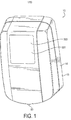
図1は本発明の実施形態に係る、プロダクトディスペンサシステムの斜視図を描く。 FIG. 1 depicts a perspective view of a product dispenser system, according to an embodiment of the present invention.
図1aは本発明の実施形態に係る、プロダクトディスペンサシステムの部分切り取り側面図を描く。 FIG. 1 a depicts a partial cutaway side view of a product dispenser system, according to an embodiment of the present invention.
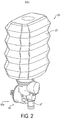
図2は本発明の実施形態に係る、プロダクトディスペンサシステムに使用のためのプロダクトリザーバの斜視図である。 FIG. 2 is a perspective view of a product reservoir for use in a product dispenser system according to an embodiment of the present invention.
図3は本発明の実施形態に係る、プロダクトリザーバ分解組立図である。 FIG. 3 is an exploded view of a product reservoir according to an embodiment of the present invention.
図4は本発明の実施形態に係る、ディスペンサシステムのためのプロダクトリザーバ、コントローラー及びエネルギー蓄積装置の側面図である。 FIG. 4 is a side view of a product reservoir, controller and energy storage device for a dispenser system according to an embodiment of the present invention.
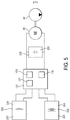
図5は本発明の実施形態に係る、プロダクトディスペンサシステムの概略図である。 FIG. 5 is a schematic diagram of a product dispenser system according to an embodiment of the present invention.
図6は本発明の実施形態に係る、中間エネルギー蓄積装置に蓄積されるエネルギーレベルの経過時間による変化を描くグラフである。 FIG. 6 is a graph depicting a change in energy level stored in the intermediate energy storage device according to an elapsed time according to an embodiment of the present invention.
図7は本発明の実施形態に係る、中間エネルギー蓄積装置に蓄積されるエネルギーレベルの時間経過による変化を描くグラフである。 FIG. 7 is a graph depicting changes over time of the energy level stored in the intermediate energy storage device according to the embodiment of the present invention.
図7aは本発明の実施形態に係る、中間エネルギー蓄積装置に蓄積されるエネルギーレベルの時間経過による変化を描くグラフである。 FIG. 7a is a graph depicting the change over time of the energy level stored in the intermediate energy storage device according to an embodiment of the present invention.
図8は本発明の実施形態に係る、中間エネルギー蓄積装置に蓄積されるエネルギーレベルの時間経過による変化を描くグラフである。 FIG. 8 is a graph depicting changes over time in the energy level stored in the intermediate energy storage device according to an embodiment of the present invention.
図9は本発明の実施形態に係る、中間エネルギー蓄積装置に蓄積されるエネルギーレベルの時間経過による変化を描くグラフである。 FIG. 9 is a graph depicting changes over time in the energy level stored in the intermediate energy storage device according to an embodiment of the present invention.
図10は本発明の実施形態に係る、本発明の方法のフロー図である。 FIG. 10 is a flow diagram of the method of the present invention according to an embodiment of the present invention.
図11は本発明の実施形態に係る、本発明の他の方法のフロー図である。 FIG. 11 is a flow diagram of another method of the present invention, according to an embodiment of the present invention.
図1に描かれる、プロダクトディスペンサシステムは、本発明の実施形態による一定量の流体プロダクトを吐出する。一例では、符号10で一般的に図示されるディスペンサシステムは、ソープ、ローション又は手の除菌用ローションのようなハンドケアプロダクトを吐出するが、他の種類のプロダクトも同様にディスペンサシステムから吐出される場合がある。 The product dispenser system depicted in FIG. 1 dispenses a quantity of fluid product according to an embodiment of the present invention. In one example, a dispenser system, generally illustrated at 10, dispenses a hand care product such as a soap, lotion or hand sanitizing lotion, although other types of products are dispensed from the dispenser system as well. There is a case.
図1と1aに図示した実施形態では、ディスペンサシステム10は、液体ディスペンサ10とも称され、ディスペンサハウジング14又は基部を含む。ディスペンサハウジング14は、流体ディスペンサ10の部品を支えるよう構成された一又は複数の壁部15から構成されている。システムの他の部品同様、ディスペンサハウジング14の製造においては、費用対効果が高いため、プラスチックが使用され得る。流体リザーバ26は流体プロダクトを流体ディスペンサ10へ供給し、そして逆向きにディスペンサハウジング14に備え付けられている。ディスペンサハウジング14の壁部15は、流体リザーバ26を受け止める上部が開放された凹形を形成し得る。特定の実施形態では、流体リザーバ26は、プロダクトリザーバ26とも称され、容易に交換可能である。このように、流体リザーバ26又はプロダクトリザーバ26は交換可能なプロダクトリザーバ26を構成する。
In the embodiment illustrated in FIGS. 1 and 1a, the
流体ディスペンサ10の後部側(図示せず)は、流体ディスペンサ10を固定構造物に備え付けるための開口部及び/又は細長い穴を含むことができる。一実施形態では、ディスペンサハウジング14は、留め具により壁又はディスペンサスタンド(図示せず)へ直接備え付けることができる。他の実施形態では、取付金具が提供され、取付金具は、取付金具が壁又は他の固定構造物に固定されるように留め具を受け止める取り付け穴を含む。この実施形態では、ディスペンサハウジング14は取付金具に取り外し可能に取り付けられることができる。流体ディスペンサの支持構造への取り付けについては、本技術分野の周知技術であり、さらなる説明は提供されない。
The rear side (not shown) of
次に、図1、1a及び2を参照すると、プロダクトリザーバ26は吐出可能なプロダクトを保持するよう構成されており、それはハンドケアプロダクトの場合もある。プロダクトリザーバ26の壁部27は、シート状の素材で構成され、流体密封(あるいは気体密封)の状態で、ポンプに取り付けるために構成された一端に開口を有する容器を形成することができる。壁部27及び/又は開口の素材、形状と大きさは、プロダクトをその中に貯蔵するのに適したものが選択される。流体リザーバ26を形成するために、ブロー成形、又は他のプラスチック成形加工が使用され得る。
Referring now to FIGS. 1, 1a and 2, the
上述のように、プロダクトリザーバ26は容易に交換可能な容器として構成されている。交換可能とは、プロダクトが空になり、密封された詰め替え交換品に取り換えられた時、容器は廃棄されることが意図されていることを意味する。プロダクトリザーバ26に加えて、ポンプとノズルもプロダクトリザーバ26が消耗した時、併せて廃棄される場合がある。よって、リザーバ、ポンプとノズルの新しい部品セットは、液体ディスペンサ10の詰め替えの都度供給され得る。
As described above, the
図2、そして図3も参照すれば、ディスペンサポンプ40の例示的実施形態が示されている。ポンプ40はポンプ入口41とポンプ出口42を含む。ポンプ出口は流体ディスペンサ10から流体プロダクトを吐出するためのノズル47に固定的に接続されている。ポンプ入口は流体リザーバ26に接続されている。特に、ポンプ入口は、流体密封あるいは気体密封の状態で、流体リザーバ26の開口に固定的に接続され密封されている。したがって、ポンプ40、ノズル47と流体リザーバ26は部品セットとして供給される。このように、流体リザーバ26の交換時、流体ディスペンサ10の濡れた部品は全て廃棄される。
With reference to FIGS. 2 and 3, an exemplary embodiment of a
ポンプ40はシステム内に圧力を誘発し、正圧あるいは負圧(真空圧)で流体をリザーバ26からノズル47へ運ぶ。特に、一実施形態では、ギアポンプ又は往復動ポンプ(gear pumps or reciprocating pumps)を含むが、限定はされない他の種類のポンプ機構が使用され得るが、ポンプ40はピストンポンプ(piston pump)40aであり得る。ポンプ40は逆止め弁であり得る一又は複数のバルブをさらに組み込むことができ、確実に、流体がポンプチャンバから流れ、ノズルを通り吐出される、すなわち、リザーバに還流しないようにする。
ポンプ40は、モータ48により動作され得る。モータ48は直流あるいは交流モータであり得る。しかし、好適な一実施形態では、モータは、一又は複数のバッテリーを含み得る搭載電源から電力を引き出す、低電圧直流モータ48であり、詳細は後述する。モータはメカニカルトランスミッションに接続され得るが、図には示されていない。トランスミッションは、モータの出力軸から提供される回転運動を、ポンプ40のピストンの往復運動に使用する直線運動へ変換し得る。特に、一実施形態では、トランスミッションはカム作動装置を含む場合がある。モータ、トランスミッションとポンプは共に各動作サイクルで流体プロダクトの所定量を吐出するように構成されている。特にモータ48はトランスミッションを組み込むことなく、ポンプへ直接接続され得る。
The
続けて図3を参照すると、プロダクトリザーバ26のコンテンツを有効化するために、有効化キー又はタグがプロダクトリザーバ26とディスペンサシステム10の間に実装され得る。特に、一実施形態では、図示されていないが、プロダクトリザーバ26は電子キーを含む。電子キーは、近距離無線通信を使用する一又は複数の種類のシステムを用い得る。具体的には、キーはRFID(無線自動識別)タグを含み、受動型でも能動型でもあり得る。対応する送信器は、図示されないが、ディスペンサハウジング14に備え付けられ得る。プロダクトリザーバ26がディスペンサ10内に設置された時、送信器は、自動的に電子キーの「接続確認」を行い、正しいプロダクトリザーバが使用されていることを検証する。もし誤ったプロダクトリザーバが設置された時、ディスペンサシステムコントローラー170はディスペンサの動作を防止するよう機能する。RFID信号の範囲、すなわち強さに応じて、送信器は、システムコントローラー170内あるいはディスペンサシステム10内のどこかに配置される回路基板上に備え付けられ得ると考えられる。代替実施形態として、図示されないが、近距離磁気誘導システムが電子タグとして使用されることが考えられる。この種類のタグ付けシステムでは、特に、同調コイル誘導子が使用され、適切なプロダクトリザーバ26が正しいディスペンサに確実に使用されるようにする。このシステムは、ディスペンサ内に配置されディスペンサコントローラー170と電気的に接続された、エミッタコイルを少なくとも一つ使用する。エミッタコイルは、一又は複数の電子部品に接続されており、電子部品には典型的にはコンデンサが含まれ得る。当業者であれば、回路内のコンデンサの配置とともに静電容量値を変えれば、電子キーイングの組み合わせがほぼ無限にできることを認識するだろう。したがって、同様に図示されないが、受信コイルが、プロダクトリザーバ26に設置され得る。その結果、受信コイルは同様にエミッタコイルと同調することとなる。このようにして、コントローラーは適切なプロダクトリザーバ26がディスペンサ10に設置されているかどうかを決定することができる。
With continued reference to FIG. 3, an activation key or tag may be implemented between the
他の実施形態では、プロダクトリザーバ26がコントローラー170に直接接続されている場合、有効化キーが使用され得る。直接接続とは、一又は複数の導体のセットが物理的に接触し、プロダクトリザーバ26の部品とディスペンサシステム10の一又は複数の部品との間で電子信号を送ることを目的とすることを意味する。有効化キーは当業者の健全な判断により選択されるいかなる形式の電子キーイングも含み得る。上記同様に、電子キーは受動型でも能動型もあり得る。特に、一実施形態では、有効化キーからプロダクトリザーバ26の外面に配置された接触端子(図示しない)に及ぶ、導体が含まれ、これは導体244であり得る。露出した端子は導体244と電気的に接続され得る、あるいは、ディスペンサシステム10内の対応する端子に直接接触するよう構成され得る。このように、プロダクトリザーバ26がディスペンサシステム10内に設置されている時、接触端子のセットが互いに電気接続し、それによりキーがコントローラー170と直接電気通信する。他の形式の電気通信は、端子の直接接続を通じて送信され得て、これにはコントローラー170での他の種類のデータ交換及び/又はプロダクトリザーバ26と搭載電源の間の電力のトランスミッションを含むが、これらに限定されるものではないことに注意されたい。それでも当業者であれば、キー付きメカニカルフィッティング(keyed mechanical fittings)や光学的センサーシステムを含む、他の形式のタグが使用可能であることを理解するであろう。ここに記述された本発明と合致するように、ディスペンサシステム10が適切なプロダクトリザーバ26とのみ動作することが確実であれば、いかなる方法であっても、選択され得る。
In other embodiments, an activation key may be used when the
特に、一実施形態では、センサ90がディスペンサシステム10内に組み込まれ得る。これらのセンサはディスペンサシステム10のハンズフリー駆動のための動作を検知するのに使用される。センサ90は、一又は複数のIRエミッターと検出器を含み得る。エミッターと検出器のペアは、ノズル16下部の特定の領域で、ディスペンサシステム10の一貫した駆動を確実にするような方法で、適応され得る。それでも、本発明の実施形態の意図する範囲から逸脱しないならば、ディスペンサシステムのハンズフリー駆動を可能とする他の種類のセンサ部品が使用され得る。
In particular, in one embodiment,
次に図4を参照すると、ディスペンサシステム10はコントローラーあるいは、ディスペンサシステム10の多様な機能を制御するための一又は複数の電子回路171を含むコントロールシステム170を含む。電子回路171は印刷回路板上に配置され、ディスペンサハウジング14内で適した筐体内に受け止められ得る。
Referring now to FIG. 4, the
電子回路171は、ディスペンサシステム10の操作に関するデータを受信し、処理するように設計されているデジタル電子回路172を含み得る。特に、デジタル電子回路172は、ディスペンサシステム10内の他の同様の部品同様、電子有効化キー40、搭載センサ90からも入力信号を受信し得る。このような回路は、キーイング装置及び/又はセンサ90の部品からの出力信号を変換するアナログ−デジタル変換器と接続し得る。リザーバ26内に残存しているプロダクトの量を測定する他のセンサが組み込まれ得る。
The
一実施形態では、デジタル電子回路172は、選択的にプログラム可能な、一又は複数の論理プロセッサ173を含み得る。論理プロセッサ173はアルゴリズムでコード化された命令を実行するよう機能する。この方法だと、論理プロセッサで実行された一連のコード化された命令は、配線回路同様、ディスペンサシステム10の動作を制御するために使用され得る。デジタル電子回路172は、電子データストレージ185又はメモリ185をさらに含むことができ、それは、論理プロセッサ内のメモリレジスタ、DRAMあるいはSD−RAMのような揮発性メモリ及び/又は不揮発性メモリの形式を含み得る。その上、デジタル電子回路172は、一又は複数のタイマー回路175(図5参照)を含み得る。タイマー回路はディスペンサシステム10がどれだけ速くあるいは頻繁に使用されているかを決定するのに使用可能である。一実施形態では、タイマー回路175は、モータ48が一定期間内に何回駆動されたか、あるいは、搭載エネルギー蓄積装置が特定の時間間隔内に再充填されたかどうかを測定するのに使用され、両方ともに、さらに後述されるように、バッテリーの放出率を調整するのに使用することもできる。
In one embodiment, digital
デジタル電子回路172は、例えば電子モータ48の動作のような、ディスペンサシステム10の動作を制御するために使用される信号を出力する機能も持つ。出力信号は低電圧直流信号を含み得る。優れた識見によりモータ48を制御する他の方法が選択される場合もあるが、出力信号は、モータ48の起動を直接制御する一又は複数の増幅器及び/又は継電器を使用し得る。ここで、モータ48の直接制御起動が、例えば中間エネルギー蓄積装置のように、電力源のモータ48への選択的接続も含むことに留意されたい。どのような構成でも、当業者は、ディスペンサシステム10のモータ48の動作制御には、必要に応じて多様な回路が使用、実施されることを理解するだろう。
The digital
図4、5を参照すると、モータ48を作動させる電力が複数の電力源から供給され得る。一実施形態では、ディスペンサシステム10は、第1の搭載エネルギー供給装置200を組み込む場合がある。第1のエネルギー供給装置200は、化学エネルギーを電気エネルギーに変換する電気化学セルを含み得る。一例として、アルカリ乾電池202が含まれ、単三電池、単二電池、単一電池を含む様々な出力容量で供給される。本発明の請求範囲を限定することなく、他の種類のバッテリー202が使用される場合もある。エネルギー供給装置200は、ディスペンサハウジング14内で受け止められたバッテリー204の列を含む場合がある。一実施形態では、バッテリー204の列は永続的にディスペンサシステム10内に設置されているものとみなされる。永続的に設置とは、バッテリー204の列がディスペンサの構造枠内に格納され、容易に取り出すことはできないということを意味する。他の実施形態では、バッテリー204の列は交換可能であるが、一般的には第1のエネルギー供給装置200のバッテリーは容易には交換可能でない。バッテリー202の大きさと容量は特定の種類のディスペンサシステム10の使用に適するように選択可能であり、限定的に解釈されるべきものでないことに留意されたい。一又は複数の代替実施形態では、モータを作動させる電源は、例として光電池を含む他のエネルギー源によって置き換えられたり、あるいは補足されたりする場合があるが、この例に限定されるものでない。
4 and 5, the power for operating the
図3と5を参照すると、第2の搭載エネルギー供給装置230は詰め替え容器26とも称されるプロダクトリザーバ26に一体化され得る。第1の搭載エネルギー供給装置200と同様に、第2のエネルギー供給装置230もまた、コントローラー170により、選択的かつ動作可能に接続され得て、モータ48を駆動するエネルギーを供給する。第2のエネルギー供給装置230は、例えばプロダクトリザーバ26のフレームやハウジングといった構造237に組み込まれている一又は複数のバッテリー233を含み得る。特定の一実施形態では、バッテリー233は低出力密度バッテリー233を含み得る。特に、一実施形態では、低出力密度バッテリー233はボタンバッテリーあるいはコイン電池バッテリー234を含む場合がある。本技術分野で周知のように、コイン電池は、サイズが小さく軽量であると同時に放出率が低いことが知られている。特に、コイン電池234は設置面積で選択され得る一方で、本発明の意図する範囲から逸脱することなく、他の種類のバッテリーもプロダクトリザーバ26内に組み込まれることができる。例えば、単三、単四アルカリ電池がプロダクトリザーバ26に一体化されることもある。プロダクトリザーバ26交換の都度、第2の搭載エネルギー供給装置230から新しいエネルギーが供給されることが容易に理解される。
With reference to FIGS. 3 and 5, the second onboard
プロダクトリザーバ26のハウジングは、第2のエネルギー供給装置230を受け止める又は収納するように構成された一又は複数の空洞を有することができる。導体板240は、第2のエネルギー供給装置230の各端子に接続しているリード線244を含み得る。コイル電池、すなわち、コインバッテリー234を内蔵する実施形態では、導線244はバッテリーの正極、負極へ接続する。導体板240はコイン電池234からコントローラー170、モータ48又は中間エネルギー蓄積装置への電流を導く導体も含み得る。このように、第2のエネルギー供給装置230又はバッテリー234はプロダクトリザーバ26、すなわち、交換可能なプロダクトリザーバ26内へ一体化されている。ここで、導線244は、上述のように、電力と同時にデータを伝送するのに使用され得ることに留意されたい。データは、キーイング情報、リザーバ26内のプロダクトの残量レベル、あるいは、プロダクトリザーバ26とコントローラー170間でやり取りされるその他の種類の情報に関係し得る。
The housing of the
上述のように、コントローラー170は第1、第2のエネルギー供給装置200、230のいずれか又は両方からモータ48を駆動するのに使用する電力を導くことができるように機能する。第1、第2のエネルギー供給装置200、230はコントローラー170に促進され、実質的に異なる複数の放出率のうちの一つの率でエネルギーを放出し得ることが理解されるであろう。特に一実施形態では、モータ48を駆動する電力は、電気的に第1、第2のエネルギー供給装置200、230とモータ48の間に位置する中間エネルギー蓄積装置220内に運ばれ、一時的に蓄積され得る。中間エネルギー蓄積装置220は、第1、第2のエネルギー供給装置200、230からのエネルギーを蓄積する能力があり、コントローラー170により制御され、選択的に接続されて、モータ48に動作電力を供給し得る。中間エネルギー蓄積装置220は、複数回の駆動サイクルを行うモータ48を駆動するのに十分なエネルギーの充填分を蓄積する能力がある。一例では、より大きなあるいは小さなエネルギー蓄積容量を持つかもしれないが、中間エネルギー蓄積装置220は、一回の充填でモータを5から15回駆動する能力がある。
As described above, the
モータ48は有限の駆動サイクルを持つという特徴がある。有限の駆動サイクルとは、モータ48が連続的にも無限にも稼働しないことを意味し、明らかな開始及び停止時間を有することを特徴とする。モータ駆動サイクルは、ディスペンサシステム10からプロダクトの1回量を吐出するポンプ駆動サイクルに直接呼応する。プロダクトが吐出されると、コントローラー170は、次の吐出動作でユーザーにより再駆動されるまでモータ48を停止する。
The
中間エネルギー蓄積装置220は、静電蓄積装置を含むことができ、一例はコンデンサ224である。コンデンサ224は、標準的な誘電体コアで構成され、あるいは電気化学コアを含み得て、一例は、超コンデンサ225を含み得る。したがって、中間エネルギー蓄積装置220は、吐出動作の合間のかなりの長時間充填を維持する能力がある。
The intermediate
中間エネルギー蓄積装置220の充填又は再充填は、コントローラー170により制御され得る。コントローラー170は、エネルギー源200、230をエネルギー蓄積装置220へ接続するための充填回路177を含み得る。一実施形態では、コントローラー170は、検出回路あるいは監視回路179も含み、超コンデンサ225すなわち中間エネルギー蓄積装置220内に残存するエネルギーの量を測定する。超コンデンサ225のエネルギーレベルの減少を探知すると、コントローラー170(論理プロセッサ173を利用する場合もある)は、超コンデンサ225が再充填されるまで一又は両方のバッテリー202、234すなわちエネルギー蓄積装置200、230を超コンデンサ225に接続する場合がある(図5−8、e1を参照)。コントローラー170は、バッテリー202、234の一又は両方を選択的に接続する機能を有し、コントローラー170により処理されるディスペンサ使用データの一部に基づき、超コンデンサ225を再充填する(以下で詳細に議論される)。上述のように、ファームウェア及び/又はソフトウェアがその過程で使用され得る。
The filling or refilling of the intermediate
好適な実施形態では、超コンデンサ225又は中間エネルギー蓄積装置220に蓄積されているエネルギーは、主にバッテリー234又は第2のエネルギー供給装置230から充電される。したがって、第1のエネルギー供給装置200(すなわち、ディスペンサハウジング内のバッテリー)により供給されるエネルギーは、主に、急速に吐出活動が起こった際に使用するバックアップ用として依存されている。一旦、超コンデンサ225内のエネルギーがエネルギー上位閾値e1のレベル(すなわち所定のエネルギーレベル)を下回ると、超コンデンサ225がモータ48へ電力を供給した時同様、コントローラー170はバッテリー234からのエネルギー放出を開始し、超コンデンサ225を再充填する。しかし、超コンデンサ225が再充填するのに十分な時間がない場合、すなわち、所定の時間間隔内で再充填する十分な時間がない場合には、コントローラー170は第1のエネルギー供給装置200から電力を引き出して、ディスペンサシステム10の動作が妨げられたり、中断されたりしないように超コンデンサ225を再充填する。
In a preferred embodiment, the energy stored in the
コントローラー170は超コンデンサ225に残存するエネルギー量に応じて異なる放出率でバッテリー234からエネルギーを引き出すことができる。一般に、コントローラー170は、バッテリー234からエネルギーが引き出される率を最小化するようにプログラムされたり、回路設計(hard wired)されている。例えば、吐出動作が起こると、コントローラー170は、バッテリー234の耐用期間を最大化するような第1の最小限の放出率でバッテリー234からエネルギーを引き出す。加えて、コントローラー170は、バッテリー234からエネルギーの引き出される率を増加するようにプログラムされ得るが、それは、超コンデンサ225に残存する充填レベルに関連して変動する。
The
図5と6を参照すると、一実施例での中間エネルギー蓄積装置220に蓄積されるエネルギーのレベルへの変化が図示されている。エネルギー蓄積装置220は当初、所定のエネルギーレベルに充填されており(図6でe1と表示される)、それはエネルギー蓄積装置220が蓄積可能であるエネルギーの最大レベルになり得る。吐出動作が起きると、エネルギー蓄積装置220からのエネルギーは放出されてモータ48を駆動する。t1とt2の間の時間は、上述のように、低電圧モータ48の有限の駆動サイクルを表す。エネルギー蓄積装置220を再充填するために(図6でt2参照)、コントローラー170は充填回路177を作動させてエネルギー供給装置230から第1の充填率310でエネルギーを引き出すことができる。再充填率310は指数関数的に変化することができ、それによりエネルギー蓄積装置220内の充填レベルは図に示されているように、初期所定電力e1のレベルに漸近する。このように、再充填率310は再充填プロファイル310と称される場合もある。特に、代替実施形態は、図7aのタイミング図により参照されているように再充填率311がほぼ線形である。
Referring to FIGS. 5 and 6, the change to the level of energy stored in the intermediate
エネルギー蓄積装置220が線形の率で再充填されても、指数関数的な率で再充填されても、エネルギー蓄積装置220を再充填する間の時間間隔(t2とtRの間の差異で示されている)は有限であると解釈されるべきである。どのようなケースでも、上述のように、エネルギーレベルが上位閾値エネルギーレベルの約95%を上回っている時、エネルギー蓄積装置220は再充填された、すなわち、フル充填されたと解釈されるべきである。
Whether the
一実施形態によれば、モータ48は再駆動が可能となる前に駆動サイクルを完了しなければならない。一旦、モータ駆動サイクルが完了したら、コントローラー170は、第2のエネルギー供給装置230からエネルギーを放出することにより中間エネルギー蓄積装置220、例えば超コンデンサ225の充填を開始する。
According to one embodiment, the
図5から7を参照すると、中間エネルギー蓄積装置220が再充填され、あるいは所定のエネルギーレベルe1まで蓄積される前に、ディスペンサシステムが再駆動された場合には(図7でt3参照)、コントローラー170は第2のエネルギー供給装置230からのエネルギーが引き出される率を変更して、中間エネルギー蓄積装置220の再充填率315、もしくは再充填プロファイル315を上昇させる。当業者であれば、再充填率315の初期勾配a2は、再充填率310の初期勾配a1よりも急であり、それは再充填率の上昇及びバッテリー234のエネルギーの引き出しの上昇を示していることを容易に理解するだろう。当業者であれば、初期、もしくは第1の再充填率、例えば、再充填率310を考慮すれば、第1の時間間隔が得られ、この時間間隔内で、エネルギー蓄積装置220が再充填されることを容易に理解するだろう。上述の議論から、モータ48が第1の時間間隔内に再駆動された場合、コントローラー170は、エネルギー蓄積装置からの第1の放出率を第2のより大きい放出率へ上昇させる。
Referring to FIGS. 5-7, if the dispenser system is re-driven before the intermediate
さらに図7を参照すると、一実施形態では、エネルギー蓄積装置220の中間エネルギーレベル参照値(一般にe2とe3により表される)は、エネルギー蓄積装置220の測定された残存エネルギーレベルとの比較のために、事前に定義され、コントローラー170に記憶された値になり得る。したがって、再充填率315、もしくは再充填プロファイル315は、エネルギー蓄積装置220で測定されたエネルギーレベルが各々の中間エネルギーレベル参照値を下回った時のみ変化する。図7は、モータ駆動サイクル300の終了に一致する中間エネルギーレベル参照値e2を示すが、それは、駆動サイクル1回分、モータ48を動作するのに必要なエネルギー量に直接関連している。しかし、中間エネルギーレベル参照値e2はモータ48が駆動サイクル1回分を動作するのに必要なエネルギー量より大きくも小さくも定義可能である。中間エネルギーレベル値は、本発明の実施形態での使用にあたり適切に定義可能である。特に、各中間閾値レベル間のエネルギーレベル値の違いは、大きさが必ずしも同じではなく変動する場合がある。例えば、e1とe2の間の差はe2とe3の間の差より大きくても小さくてもよい。
Still referring to FIG. 7, in one embodiment, the intermediate energy level reference value of energy storage device 220 (generally represented by e 2 and e 3 ) is compared to the measured residual energy level of
図8を参照し、本発明の他の実施形態が次に議論される。低位閾値エネルギーレベルenが定義され、それによりエネルギー蓄積装置220の残存エネルギーレベルは臨界的に低いと考えられる。これは、比較的短い時間内にディスペンサ10が繰り返し駆動されたときに発生し得る。この状況で、コインバッテリー234であり得る第2のエネルギー供給装置230は、現在のディスペンサ活動レベルではエネルギー供給装置220を再充填する能力がないかもしれない。この状況を防止するために、コントローラー170は、電力蓄積装置220内のエネルギーレベルが下位閾値エネルギーレベルenを下回った時点を検知するようにプログラムされ得る。このとき、コントローラー170はエネルギー蓄積装置220を再充填するようにエネルギーを第1のエネルギー供給装置200から導くが、第1のエネルギー供給装置200はディスペンサハウジング内に格納されているバッテリーであり得る。特に、一実施形態では、第1のエネルギー供給装置200は第2のエネルギー供給装置230にエネルギーを補充して、エネルギー蓄積装置220を再充填するものと考えられる。しかし、他の実施形態では、第1のエネルギー供給装置200は、第2のエネルギー供給装置230の替わりに、エネルギー蓄積装置220を再充填するために接続されると考えられる。換言すれば、この実施形態では、エネルギー蓄積装置220の再充填により、第2のエネルギー供給装置230は動作停止する。
With reference to FIG. 8, another embodiment of the present invention will now be discussed. Are defined low threshold energy level e n, thereby remaining energy level of the
図9を参照すれば、一実施形態では、コントローラー170は、モータ48が急速に駆動されるまで第1の再充填率310を上昇させない。つまり、コントローラー170は、所定の時間間隔Tp内で吐出動作が数回起こった後初めて、エネルギー供給装置230からエネルギーを引き出す率を上昇させる。例えば、ディスペンサシステム10が最初に駆動されたとき、コントローラー170は、モータ48の駆動後、t2から開始し、第1の再充填率310でエネルギー蓄積装置220を再充填する。コントローラー170は同時にタイマーを起動する。もし、タイマーTpが切れる前にモータ48が2回以上駆動されれば、コントローラー170は再充填率を上昇させエネルギー蓄積装置220のエネルギーをより速やかに補充する。換言すれば、コントローラー170が蓄積装置220のエネルギーレベルの急低下を検知すると、コントローラー170は第2のエネルギー供給装置230から放出されるエネルギーの放出率を上昇させ、エネルギー蓄積装置220を再充填する。特に、コントローラーが供給装置230からエネルギーを引き出す率を調整する前に、所定の時間枠内で発生するはずの吐出動作(すなわち、モータ駆動サイクル)数は、ある特定のディスペンサシステムの使用に適合するように調整することができる。
Referring to FIG. 9, in one embodiment, the
本発明の他の実施形態では、エネルギー供給装置230の放出率の変化は、吐出動作が起きる速さだけでなく、プロダクトリザーバ26に残存する流体プロダクトの量にも関係するプロファイルに従う。この実施形態では、コントローラー170は、ディスペンサシステム10駆動の都度、具体的にはモータ駆動の都度、値が増加する、カウンティング回路を使用することができる。上述のことはディスペンサ利用データがコントローラー170により収集される一実施形態を示している。そのカウンターから、コントローラー170は、プロダクトリザーバ26内に残存するプロダクトの量を算出することができる。したがって、コントローラー170は、プロダクトリザーバ26内のプロダクト残量に基づいて供給装置230の放出率を調整可能である。プロダクトリザーバ26内に残存するプロダクト容量がより大きいと、上述した実施形態同様、コントローラー170は供給装置230からエネルギーをより低い引き出す放出率プロファイルに従う。しかし、例えば、容器が空に近づいているときなど、供給装置200内のプロダクト残量が比較的少ない状況では、コントローラー170は供給装置230から積極的にエネルギーを引き出す。換言すれば、エネルギー蓄積装置220を再充填するために、エネルギー供給装置230からエネルギーが引き出される率は、コントローラー170により、プロダクトリザーバ26内に残存するプロダクト容量が多い場合第1の低位放出率に、プロダクトリザーバ26内に残存するプロダクト容量が少ない場合第2の高位放出率に、設定され得る。
In other embodiments of the present invention, the change in the rate of release of the
特に、一実施形態では、コントローラー170はプロダクトリザーバ26内に残存する流体プロダクトの4つの残量レベルに基づき、蓄積装置220の放出率を調整するようにプログラムされ得る。4つの残量レベルはプロダクトリザーバ26の満タン時の4分の1毎に、すなわち、25%、50%、75%、100%で発生し得る。しかし、残量レベルが等しい大きさでなく、蓄積装置220のサイズ、すなわち、蓄積容量に基づいて不均等に重さが決まる場合もある。例えば、第1の残量レベルは、プロダクトリザーバ26にプロダクトの50%が残っているときに設定され得る。続いて第2の残量レベルは25%に設定され得る。残る2つのレベルは、各12%と6%に設定され得る。当業者であれば、ある特定の種類のプロダクトリザーバ26に有用になるように、他の非線形プロファイルもあり得ることが理解できよう。
In particular, in one embodiment, the
再び図3を参照すると、プロダクトリザーバ26は、一般的に210で示されるメモリー記憶装置を含むことができる。メモリー記憶装置210は、例えば、読み取り専用メモリー、フラッシュメモリー、及び/又は光学又は磁気メモリー記憶を含む不揮発性メモリー212を含むことができる。特に、メモリー記憶装置210はディスペンサへ設置後に書き込み可能であるメモリーを含む。続いて、メモリー記憶装置210は、コントローラー170と電気的に接続可能であり、情報がメモリー装置210から読み込み可能、及び/又はメモリー記憶装置210へダウンロード可能となる。メモリー、すなわち、メモリー記憶装置210は、プロダクトディスペンサ10を動作するためのコントローラー及び/又は論理プロセッサにより使用される情報を、記憶させるために使用可能である。このような情報は、論理プロセッサにより実行可能であるアルゴリズムを示すデータを含み得る。メモリーはセンサフィードバックに関わるデータを記憶させるために使用できる。加えて、メモリーは、永続的でも一時的でもいずれでも、ディスペンサ利用データに関する情報を記憶させるのに用いられ得る。さらに、メモリー記憶装置210を利用するいかなる方法でも本発明の実施形態で使用するのに適合するように選択され得る。当業者であれば、メモリー装置210とコントローラー170の間の電気通信は、有線接続と同様に無線通信も含み得ることを理解するであろう。
Referring again to FIG. 3, the
好適な一実施形態では、メモリー記憶装置210は、最初にプロダクトリザーバ26に記憶されているプロダクト量に関する情報を記憶しているフラッシュメモリー212aを含む。具体的には、フラッシュメモリー212aはプロダクトリザーバ26に蓄積されているプロダクトの初期量を特定するデータを蓄積し、吐出動作の後その都度、プロダクトリザーバ26に残存するプロダクト量に関するデータを記憶できる。特に、他の種類の情報もメモリー装置210に記憶され得る。このような情報は、当業者が適切と考える他の情報同様に、プロダクトリザーバ設置日、プロダクト使用期限情報、プロダクトリザーバに貯蔵されているプロダクトの種類(すなわち、キーイング又はタグ情報)といった情報を含み得るが、限定するものではない。したがって、中間エネルギー蓄積装置220同様、第1、第2のエネルギー供給装置200、230からエネルギーを引き出すのに使用される放出プロファイルは、メモリー装置210に記憶されているデータに応じてコントローラー170により管理され得る。
In one preferred embodiment, the
本発明の他の実施形態として、プロダクトリザーバ26に残存するプロダクト容量がゼロに近づいたとき、あるいは、この残存するプロダクト容量が残存プロダクトの最小閾値よりも少なくなったとき、バッテリー233から意図的にエネルギーを消耗することが考えられる。閾値に達すると、コントローラー170はバッテリー233を一又は複数のエネルギードレーン回路215(図4参照)へ接続するが、その回路は抵抗器又は他の短絡装置を含み、バッテリー233のエネルギーを実質的に消耗させる、あるいは枯渇させる。特に、コントローラー170は中間エネルギー蓄積装置220に蓄積されているエネルギーのレベルをバッテリー233が消耗する前にチェック可能である。このように、中間エネルギー蓄積装置220は、必要に応じて再充填可能であり、したがって、その廃棄前にバッテリーの有用性を最大化する。いずれにしろ、プロダクトリザーバ26搭載の記憶されたメモリー、すなわちメモリー装置210からの情報は、エネルギードレーン回路215の使用に適切な時期を決定するのに使用することができる。
As another embodiment of the present invention, when the product capacity remaining in the
ここに記述された実施形態のいくつかは、モータを動作する電力の供給の特定の適用を議論しているが、同様にディスペンサシステム10の他の部品についても適用可能であることに注意されたい。例えば、現在は上記と同様の方法で別の実施形態が述べられているが、コントローラー170はハウジング14に受け止められているディスプレイユニット300を動作する電力を提供することができる。ディスプレイユニット300は、視覚又は音声でユーザーとつながる、LCDディスプレイ301、あるいは、他のディスプレイ装置を含み得る。バッテリーの状態又はリザーバ詰め替え残量レベルのような情報がディスプレイ300に表示され得る。加えて、ディスプレイ300には広告を表示することもできる。さらに他の情報も表示可能であり、ネットワーク接続性に関するもの、あるいは、衛生コンプライアンスの監視にディスペンサデータが使用される場合のディスペンサ使用量に関するものもあり得る。他のディスペンサシステム部品の例は、ソレノイド、ワイヤレストランシーバー、表示ライト及びその類を含む。このような装置は定期的に駆動され、同様に、有限の駆動サイクルを有する場合がある。したがって、これらの種類の装置を動作する電力は中間エネルギー蓄積装置220から供給され得る。続いて、中間エネルギー蓄積装置220の再充填は、上述のモータ48の再充填と同様の方法で行われる。このように、ここに記述された原理は、どのようなディスペンサシステム部品へも適用可能である。
It should be noted that some of the embodiments described herein discuss specific applications of supplying power to operate a motor, but are equally applicable to other parts of the
一又は複数の実施形態に、ディスペンサシステムの原理が描かれ、そして記載されたが、本発明はこのような原理から乖離することなく、配置構成及び詳細が修正可能であることは当業者に容易に明らかであろう。 While the principles of the dispenser system have been depicted and described in one or more embodiments, it will be readily apparent to those skilled in the art that the arrangement and details can be modified without departing from such principles. It will be obvious.
Claims (20)
ディスペンサハウジングと;
関連するプロダクトを貯蔵するための交換容易なプロダクトリザーバと;
前記交換容易なプロダクトリザーバと一体化したバッテリーと;
前記交換容易なプロダクトリザーバに流体的に接続された入口を有するポンプであり、前記関連するプロダクトを吐出するための出口を有する前記ポンプと;
前記ポンプを駆動するために動作可能に連結された、低電圧電動モータと;
前記モータに動作電力を提供するために動作可能に接続されている中間エネルギー蓄積装置であり、複数の駆動サイクルを通じて前記モータを駆動するのに十分な所定のエネルギーレベルを蓄積するように構成されている前記中間エネルギー蓄積装置と;そして、
前記モータを選択的に駆動するように動作可能に接続されているコントローラーであり、前記バッテリー及び前記中間エネルギー蓄積装置に動作可能に接続され、前記中間エネルギー蓄積装置を前記エネルギーレベルまで再充填するために、駆動されている前記モータに応じて、前記バッテリーからエネルギーの放出を開始する、前記コントローラーとを含み、
前記コントローラーは、実質的に異なる複数の放出率のうちの所定の放出率で前記バッテリーからのエネルギー放出を選択的に開始するよう機能し、そして、
前記モータが駆動するとき、前記中間エネルギー蓄積装置が前記エネルギーレベルまで実質的に再充填されなかった場合、前記コントローラーが前記バッテリーからの放出エネルギーの放出率を変えるプロダクトディスペンサ。 A product dispenser,
A dispenser housing;
An easily replaceable product reservoir for storing related products;
A battery integrated with the easily replaceable product reservoir;
A pump having an inlet fluidly connected to the easily replaceable product reservoir and having an outlet for discharging the associated product;
A low voltage electric motor operably coupled to drive the pump;
An intermediate energy storage device operatively connected to provide operating power to the motor and configured to store a predetermined energy level sufficient to drive the motor through a plurality of drive cycles. Said intermediate energy storage device; and
A controller operably connected to selectively drive the motor, operably connected to the battery and the intermediate energy storage device, for refilling the intermediate energy storage device to the energy level; And in response to the motor being driven, the controller starts releasing energy from the battery,
The controller functions to selectively initiate energy release from the battery at a predetermined emission rate among a plurality of substantially different emission rates; and
A product dispenser in which, when the motor is driven, the controller changes the rate of release of energy released from the battery if the intermediate energy storage device has not been substantially refilled to the energy level.
前記モータを前記第1の時間間隔内で再び駆動するのに応じて、前記コントローラーは前記第1の放出率をより大きな第2の放出率へ上昇させる、請求項1記載のプロダクトディスペンサ。 In response to driving the motor, the controller starts releasing energy from the battery at a first release rate and refills the intermediate energy storage device within a first time interval; and
The product dispenser of claim 1, wherein in response to driving the motor again within the first time interval, the controller increases the first release rate to a larger second release rate.
前記コントローラーは、前記中間エネルギー蓄積装置を再充填するために、前記交換容易なプロダクトリザーバと一体化した前記バッテリー、及び前記ディスペンサハウジングへ動作可能に備え付けられたエネルギー源の一方又は両方からの、エネルギー放出を選択的に開始するように機能する、請求項1記載のプロダクトディスペンサ。 An energy source operably provided to the dispenser housing operably connected to the intermediate energy device; and
The controller includes energy from one or both of the battery integrated with the easily replaceable product reservoir and an energy source operably provided to the dispenser housing to refill the intermediate energy storage device. The product dispenser of claim 1, which functions to selectively initiate release.
ディスペンサハウジングと、関連するプロダクトを貯蔵するためのプロダクトリザーバと、前記プロダクトリザーバへ流体的に接続されている入口を有するポンプであり、前記関連プロダクトを吐出するための出口を有する前記ポンプと、前記ポンプを駆動するために動作可能に連結されているモータと、前記モータへ動作電力を提供するために動作可能に接続されている中間エネルギー蓄積装置と、前記中間エネルギー蓄積装置を再充填するための低出力密度バッテリーと、前記中間エネルギー蓄積装置を再充填するために、前記低出力密度バッテリーと前記中間エネルギー蓄積装置に動作可能に接続されている充填回路を有するコントローラーであり、有限の駆動サイクル内で動作する前記モータを駆動するよう動作可能に接続されている駆動回路を含む前記コントローラーとを有するプロダクトディスペンサを提供するステップと;
前記モータを駆動し、前記関連するプロダクトの所定の量を吐出するステップと;
前記低出力密度バッテリーから、所定の放出率でエネルギーを放出し、第1の時間間隔内で、前記中間エネルギー蓄積装置を再充填するステップと;
前記第1の時間間隔内で前記モータを再駆動するステップと;そして、
前記バッテリーから放出されたエネルギーの放出率を上昇させ、前記第1の時間間隔内で前記モータを再駆動するのに応じて、前記中間エネルギー蓄積装置を再充填するステップとを含む方法。 A method of operating a product dispenser, comprising:
A pump having a dispenser housing, a product reservoir for storing related products, and an inlet fluidly connected to the product reservoir, the pump having an outlet for discharging the related products; A motor operably coupled to drive a pump; an intermediate energy storage device operably connected to provide operating power to the motor; and refilling the intermediate energy storage device A controller having a low power density battery and a filling circuit operatively connected to the low power density battery and the intermediate energy storage device to refill the intermediate energy storage device, and within a finite drive cycle Operably connected to drive the motor operating at Providing a product dispenser having a said controller including a drive circuit;
Driving the motor to dispense a predetermined amount of the associated product;
Releasing energy from the low power density battery at a predetermined release rate and refilling the intermediate energy storage device within a first time interval;
Re-driving the motor within the first time interval; and
Recharging the intermediate energy storage device in response to increasing the rate of release of energy released from the battery and re-driving the motor within the first time interval.
前記モータを駆動し、関連するプロダクトの所定の量を吐出する前記ステップは:
関連するユーザーの前記動作を検知するのに応じて、自動的に前記モータを駆動し、関連するプロダクトの所定の量を吐出するステップを含む、請求項9記載の方法。 Providing a product dispenser having a sensor configured to sense an associated user action, the sensor having an output operatively connected to the drive circuit of the controller; and The steps of driving the motor and dispensing a predetermined amount of the associated product are:
The method of claim 9, comprising automatically driving the motor and dispensing a predetermined amount of the associated product in response to detecting the motion of the associated user.
前記プロダクトリザーバは容易に交換可能で使い捨て可能なプロダクトリザーバである、請求項9記載の方法。 The method of claim 9, wherein the low power density battery is a coin battery integrated into the product reservoir, and the product reservoir is an easily replaceable and disposable product reservoir.
前記中間エネルギー蓄積装置に蓄積されている前記エネルギーレベルを監視するステップをさらに含む、請求項9記載の方法。 The controller includes a monitoring circuit operably connected to the intermediate energy storage device to monitor the energy level stored in the intermediate energy storage device;
The method of claim 9, further comprising monitoring the energy level stored in the intermediate energy storage device.
前記ディスペンサハウジングへ動作可能に備え付けられた他のエネルギー源を有するプロダクトディスペンサを提供するステップをさらに含み、そして、
前記臨界的に低い閾値エネルギーレベルを下回った前記中間エネルギー蓄積装置内のエネルギーレベルに応じて、前記コントローラーは、前記低出力密度バッテリーと他のエネルギー源の一又は両方から前記中間エネルギー蓄積装置を選択的に再充填する、請求項13記載の方法。 Defining a critically low threshold energy level stored in the intermediate energy storage device;
Providing a product dispenser having other energy sources operably mounted to the dispenser housing; and
Depending on the energy level in the intermediate energy storage device below the critically low threshold energy level, the controller selects the intermediate energy storage device from one or both of the low power density battery and other energy sources. 14. A method according to claim 13, wherein the refilling is carried out.
ディスペンサハウジングと、関連するプロダクトを蓄積するための交換容易なプロダクトリザーバと、前記プロダクトリザーバへ流体的に接続されている入口を有するポンプであり、前記関連プロダクトを吐出するための出口を有する前記ポンプと、前記ポンプを作動させるために動作可能に連結されている低電圧モータと、前記モータへ動作電力を提供するために動作可能に接続されている中間エネルギー蓄積装置であり、前記モータを複数回駆動するのに十分な量のエネルギーを蓄積するよう構成されている前記中間エネルギー蓄積装置と、前記中間エネルギー蓄積装置を再充填するための低出力密度バッテリーであり、交換容易なプロダクトリザーバに一体化された前記低出力密度バッテリーと、前記低出力密度バッテリー及び前記中間エネルギー蓄積装置に動作可能に接続された充填回路を有するコントローラーであり、前記モータを駆動するために動作可能に接続された駆動回路を含み、前記駆動回路が前記モータを駆動した回数をカウントするよう構成されたカウンター回路を含む前記コントローラーとを有するプロダクトディスペンサを提供するステップと;
前記モータを駆動するのに応じて前記カウンター回路の値を増加させるステップと;
前記カウンター回路のカウントが所定のカウンター値を下回っているとき、前記モータを駆動するのに応じて、第1の再充填率で前記中間エネルギー蓄積装置を再充填するステップと;そして、
前記カウンター回路のカウントが前記所定のカウンター値を超えたとき、前記モータを駆動するのに応じて、実質的に異なる第2の再充填率で前記中間エネルギー蓄積装置を再充填するステップとを含む方法。 A method of operating a product dispenser, comprising:
A pump having a dispenser housing, an easily replaceable product reservoir for storing related products, and an inlet fluidly connected to said product reservoir, said pump having an outlet for discharging said related products A low voltage motor operably coupled to actuate the pump, and an intermediate energy storage device operably connected to provide operating power to the motor, the motor being driven a plurality of times The intermediate energy storage device configured to store a sufficient amount of energy to drive, and a low power density battery for refilling the intermediate energy storage device, integrated into an easily replaceable product reservoir Said low power density battery, said low power density battery and said medium A controller having a filling circuit operably connected to an energy storage device, including a drive circuit operably connected to drive the motor, wherein the drive circuit counts the number of times the motor has been driven; Providing a product dispenser having said controller including a configured counter circuit;
Increasing the value of the counter circuit in response to driving the motor;
Refilling the intermediate energy storage device at a first refill rate in response to driving the motor when the counter circuit count is below a predetermined counter value; and
Refilling the intermediate energy storage device at a substantially different second refill rate in response to driving the motor when the counter circuit count exceeds the predetermined counter value. Method.
前記カウンター回路のカウントが前記所定のカウンター値を超えたとき、前記モータを駆動するのに応じて、より大きな第2の再充填率で前記中間エネルギー蓄積装置を再充填するステップを含む、請求項16記載の方法。 When the count of the counter circuit exceeds the predetermined counter value, the step of refilling the intermediate energy storage device at a substantially different second refill rate in response to driving the motor; :
Refilling the intermediate energy storage device with a second refill rate that is greater in response to driving the motor when the counter circuit count exceeds the predetermined counter value. 16. The method according to 16.
前記カウンター回路のカウントが前記所定のカウンター値を超えたとき、前記モータを駆動するのに応じて、実質的に異なる第2の再充填率で前記中間エネルギー蓄積装置を再充填する前記ステップは:
前記カウンター回路のカウントが前記所定のカウンター値を超えたとき、前記モータを駆動するのに応じて、所定の時間間隔内で、実質的に異なる第2の再充填率で前記中間エネルギー蓄積装置を再充填するステップを含む、請求項16記載の方法。 Further comprising providing a controller having a timer circuit; and
When the counter circuit count exceeds the predetermined counter value, the step of refilling the intermediate energy storage device with a substantially different second refill rate in response to driving the motor includes:
When the counter circuit count exceeds the predetermined counter value, the intermediate energy storage device is driven at a substantially different second refill rate within a predetermined time interval in response to driving the motor. The method of claim 16, comprising refilling.
Applications Claiming Priority (5)
| Application Number | Priority Date | Filing Date | Title |
|---|---|---|---|
| US201461977962P | 2014-04-10 | 2014-04-10 | |
| US61/977,962 | 2014-04-10 | ||
| US14/682,664 | 2015-04-09 | ||
| US14/682,664 US9877617B2 (en) | 2014-04-10 | 2015-04-09 | Control for product dispenser energy storage device |
| PCT/US2015/025157 WO2015157541A1 (en) | 2014-04-10 | 2015-04-09 | Control for product dispenser energy storage device |
Related Child Applications (1)
| Application Number | Title | Priority Date | Filing Date |
|---|---|---|---|
| JP2019043533A Division JP6764967B2 (en) | 2014-04-10 | 2019-03-11 | Product dispenser |
Publications (3)
| Publication Number | Publication Date |
|---|---|
| JP2017512599A JP2017512599A (en) | 2017-05-25 |
| JP2017512599A5 JP2017512599A5 (en) | 2018-07-12 |
| JP6564970B2 true JP6564970B2 (en) | 2019-08-28 |
Family
ID=54288406
Family Applications (2)
| Application Number | Title | Priority Date | Filing Date |
|---|---|---|---|
| JP2016560957A Active JP6564970B2 (en) | 2014-04-10 | 2015-04-09 | Control of product dispenser energy storage device |
| JP2019043533A Active JP6764967B2 (en) | 2014-04-10 | 2019-03-11 | Product dispenser |
Family Applications After (1)
| Application Number | Title | Priority Date | Filing Date |
|---|---|---|---|
| JP2019043533A Active JP6764967B2 (en) | 2014-04-10 | 2019-03-11 | Product dispenser |
Country Status (5)
| Country | Link |
|---|---|
| US (1) | US9877617B2 (en) |
| JP (2) | JP6564970B2 (en) |
| AU (1) | AU2015243419B2 (en) |
| CA (1) | CA2945315C (en) |
| WO (1) | WO2015157541A1 (en) |
Families Citing this family (14)
| Publication number | Priority date | Publication date | Assignee | Title |
|---|---|---|---|---|
| NL2011347C2 (en) * | 2013-08-28 | 2015-03-03 | Ipn Ip Bv | Fluid dose-measuring device. |
| CA2948023A1 (en) | 2015-11-09 | 2017-05-09 | Gojo Industries, Inc. | Systems for providing condition-based data from a user interactive device |
| GB201520277D0 (en) * | 2015-11-17 | 2015-12-30 | Kennedy Hygiene Products Ltd | Dispensing apparatus and method |
| USD806435S1 (en) * | 2016-05-27 | 2018-01-02 | Vi-Jon, Inc. | Dispenser assembly |
| USD811770S1 (en) * | 2016-06-21 | 2018-03-06 | Gojo Industries, Inc. | Wall mounted dispenser cabinet |
| USD802329S1 (en) * | 2016-06-21 | 2017-11-14 | Gojo Industries, Inc. | Wall mounted dispenser cabinet |
| USD824693S1 (en) * | 2016-08-24 | 2018-08-07 | Vi-Jon, Inc. | Dispenser assembly |
| USD862112S1 (en) | 2016-09-21 | 2019-10-08 | Gojo Industries, Inc. | Dispenser |
| USD815457S1 (en) | 2016-10-31 | 2018-04-17 | Gojo Industries, Inc. | Wall mounted dispenser cabinet |
| USD809821S1 (en) | 2016-10-31 | 2018-02-13 | Gojo Industries, Inc. | Wall mounted dispenser cabinet |
| USD820614S1 (en) | 2016-11-28 | 2018-06-19 | Gojo Industries, Inc. | Wall mounted dispenser cabinet |
| WO2018170059A1 (en) * | 2017-03-14 | 2018-09-20 | Gojo Industries, Inc. | Refilling systems, refillable containers and method for refilling containers |
| US10561262B2 (en) * | 2017-03-15 | 2020-02-18 | Pacific Market International, Llc | Beverage container with non-manual lid operation |
| CA180428S (en) * | 2017-11-07 | 2019-04-15 | Lisbona Vives Andrea | Soap dispenser |
Family Cites Families (10)
| Publication number | Priority date | Publication date | Assignee | Title |
|---|---|---|---|---|
| US4722372A (en) * | 1985-08-02 | 1988-02-02 | Louis Hoffman Associates Inc. | Electrically operated dispensing apparatus and disposable container useable therewith |
| JPH11104030A (en) * | 1997-09-30 | 1999-04-20 | Sanyo Electric Co Ltd | Discharge device for liquid detergent |
| US6209752B1 (en) * | 1999-03-10 | 2001-04-03 | Kimberly-Clark Worldwide, Inc. | Automatic soap dispenser |
| JP2002287220A (en) * | 2001-03-28 | 2002-10-03 | Minolta Co Ltd | Flash charging device for camera |
| US8087543B2 (en) | 2007-02-01 | 2012-01-03 | Simplehuman, Llc | Electric soap dispenser |
| US20080269724A1 (en) * | 2007-04-27 | 2008-10-30 | Medtronic, Inc. | Implantable drug delivery device with programmable rate capacitor charge control |
| US8302812B2 (en) * | 2009-06-19 | 2012-11-06 | Gojo Industries, Inc. | Dispenser with discrete dispense cycles |
| US8860347B2 (en) * | 2011-11-29 | 2014-10-14 | Dispensing Dynamics International | Apparatus for reducing current drain and current spike impact on battery-powered electronic dispensers |
| US9172266B2 (en) * | 2013-02-19 | 2015-10-27 | Gojo Industries, Inc. | Power systems for touch free dispensers and refill units containing a power source |
| US9204765B2 (en) | 2012-08-23 | 2015-12-08 | Gojo Industries, Inc. | Off-axis inverted foam dispensers and refill units |
-
2015
- 2015-04-09 US US14/682,664 patent/US9877617B2/en active Active
- 2015-04-09 JP JP2016560957A patent/JP6564970B2/en active Active
- 2015-04-09 AU AU2015243419A patent/AU2015243419B2/en active Active
- 2015-04-09 CA CA2945315A patent/CA2945315C/en active Active
- 2015-04-09 WO PCT/US2015/025157 patent/WO2015157541A1/en active Application Filing
-
2019
- 2019-03-11 JP JP2019043533A patent/JP6764967B2/en active Active
Also Published As
| Publication number | Publication date |
|---|---|
| US20150320265A1 (en) | 2015-11-12 |
| AU2015243419A1 (en) | 2016-11-24 |
| WO2015157541A1 (en) | 2015-10-15 |
| CA2945315C (en) | 2022-07-12 |
| JP2019155100A (en) | 2019-09-19 |
| JP2017512599A (en) | 2017-05-25 |
| AU2015243419B2 (en) | 2019-11-28 |
| CA2945315A1 (en) | 2015-10-15 |
| US9877617B2 (en) | 2018-01-30 |
| JP6764967B2 (en) | 2020-10-07 |
Similar Documents
| Publication | Publication Date | Title |
|---|---|---|
| JP6564970B2 (en) | Control of product dispenser energy storage device | |
| JP2017512599A5 (en) | ||
| US9172266B2 (en) | Power systems for touch free dispensers and refill units containing a power source | |
| DK2217383T3 (en) | Dispensing with magnet and coil to generate energy | |
| JP5999456B2 (en) | Touch-free dispenser that operates in one cell and has battery banking function | |
| US6209752B1 (en) | Automatic soap dispenser | |
| US20170049276A1 (en) | Power systems for dynamically controlling a soap, sanitizer or lotion dispenser drive motor | |
| US11930970B2 (en) | Dispensers and dispenser systems for precisely controlled output dosing of soap or sanitizer | |
| EP3539431B1 (en) | Control for product dispenser energy storage device | |
| US20210099004A1 (en) | Dispenser energy on refill unit | |
| US20230111480A1 (en) | Power systems for touch-free dispensers | |
| NL2015629B1 (en) | Fluid dispenser. |
Legal Events
| Date | Code | Title | Description |
|---|---|---|---|
| A621 | Written request for application examination |
Free format text: JAPANESE INTERMEDIATE CODE: A621 Effective date: 20180406 |
|
| A521 | Request for written amendment filed |
Free format text: JAPANESE INTERMEDIATE CODE: A523 Effective date: 20180531 |
|
| A977 | Report on retrieval |
Free format text: JAPANESE INTERMEDIATE CODE: A971007 Effective date: 20190129 |
|
| TRDD | Decision of grant or rejection written | ||
| A01 | Written decision to grant a patent or to grant a registration (utility model) |
Free format text: JAPANESE INTERMEDIATE CODE: A01 Effective date: 20190208 |
|
| A711 | Notification of change in applicant |
Free format text: JAPANESE INTERMEDIATE CODE: A711 Effective date: 20190311 |
|
| A61 | First payment of annual fees (during grant procedure) |
Free format text: JAPANESE INTERMEDIATE CODE: A61 Effective date: 20190311 |
|
| A601 | Written request for extension of time |
Free format text: JAPANESE INTERMEDIATE CODE: A601 Effective date: 20190711 |
|
| A521 | Request for written amendment filed |
Free format text: JAPANESE INTERMEDIATE CODE: A523 Effective date: 20190717 |
|
| R150 | Certificate of patent or registration of utility model |
Ref document number: 6564970 Country of ref document: JP Free format text: JAPANESE INTERMEDIATE CODE: R150 |
|
| R250 | Receipt of annual fees |
Free format text: JAPANESE INTERMEDIATE CODE: R250 |
|
| R250 | Receipt of annual fees |
Free format text: JAPANESE INTERMEDIATE CODE: R250 |