JP6564589B2 - Product packaging box - Google Patents
Product packaging box Download PDFInfo
- Publication number
- JP6564589B2 JP6564589B2 JP2015050378A JP2015050378A JP6564589B2 JP 6564589 B2 JP6564589 B2 JP 6564589B2 JP 2015050378 A JP2015050378 A JP 2015050378A JP 2015050378 A JP2015050378 A JP 2015050378A JP 6564589 B2 JP6564589 B2 JP 6564589B2
- Authority
- JP
- Japan
- Prior art keywords
- plate
- locking
- piece
- folding
- lid
- Prior art date
- Legal status (The legal status is an assumption and is not a legal conclusion. Google has not performed a legal analysis and makes no representation as to the accuracy of the status listed.)
- Active
Links
- 238000004806 packaging method and process Methods 0.000 title claims description 105
- 239000000725 suspension Substances 0.000 claims description 6
- 210000002105 tongue Anatomy 0.000 description 119
- 108700019909 BL 19 Proteins 0.000 description 16
- 239000000123 paper Substances 0.000 description 16
- 230000004308 accommodation Effects 0.000 description 7
- 101000575029 Bacillus subtilis (strain 168) 50S ribosomal protein L11 Proteins 0.000 description 6
- 102100035793 CD83 antigen Human genes 0.000 description 6
- 101000946856 Homo sapiens CD83 antigen Proteins 0.000 description 6
- 230000000694 effects Effects 0.000 description 6
- 230000005489 elastic deformation Effects 0.000 description 6
- 230000014759 maintenance of location Effects 0.000 description 5
- 101000874141 Homo sapiens Probable ATP-dependent RNA helicase DDX43 Proteins 0.000 description 4
- 102100035724 Probable ATP-dependent RNA helicase DDX43 Human genes 0.000 description 4
- -1 polyethylene terephthalate Polymers 0.000 description 4
- 101710190981 50S ribosomal protein L6 Proteins 0.000 description 3
- 101710190962 50S ribosomal protein L9 Proteins 0.000 description 3
- 101001105315 Bacillus subtilis (strain 168) 50S ribosomal protein L17 Proteins 0.000 description 3
- 101000682328 Bacillus subtilis (strain 168) 50S ribosomal protein L18 Proteins 0.000 description 3
- 101000592939 Bacillus subtilis (strain 168) 50S ribosomal protein L24 Proteins 0.000 description 3
- 101001070329 Geobacillus stearothermophilus 50S ribosomal protein L18 Proteins 0.000 description 3
- 101001093025 Geobacillus stearothermophilus 50S ribosomal protein L7/L12 Proteins 0.000 description 3
- 101001057156 Homo sapiens Melanoma-associated antigen C2 Proteins 0.000 description 3
- 102100027252 Melanoma-associated antigen C2 Human genes 0.000 description 3
- 239000000463 material Substances 0.000 description 3
- 230000002093 peripheral effect Effects 0.000 description 3
- 229920000139 polyethylene terephthalate Polymers 0.000 description 3
- 239000005020 polyethylene terephthalate Substances 0.000 description 3
- 101001101476 Bacillus subtilis (strain 168) 50S ribosomal protein L21 Proteins 0.000 description 2
- 101000633613 Homo sapiens Probable threonine protease PRSS50 Proteins 0.000 description 2
- 102100029523 Probable threonine protease PRSS50 Human genes 0.000 description 2
- 230000001154 acute effect Effects 0.000 description 2
- 239000000853 adhesive Substances 0.000 description 2
- 230000001070 adhesive effect Effects 0.000 description 2
- XAGFODPZIPBFFR-UHFFFAOYSA-N aluminium Chemical compound [Al] XAGFODPZIPBFFR-UHFFFAOYSA-N 0.000 description 2
- 229910052782 aluminium Inorganic materials 0.000 description 2
- 238000005452 bending Methods 0.000 description 2
- 238000003780 insertion Methods 0.000 description 2
- 230000037431 insertion Effects 0.000 description 2
- 239000004743 Polypropylene Substances 0.000 description 1
- 239000004793 Polystyrene Substances 0.000 description 1
- 239000003795 chemical substances by application Substances 0.000 description 1
- 239000011248 coating agent Substances 0.000 description 1
- 238000000576 coating method Methods 0.000 description 1
- 239000002537 cosmetic Substances 0.000 description 1
- 239000003814 drug Substances 0.000 description 1
- 239000003973 paint Substances 0.000 description 1
- 239000000049 pigment Substances 0.000 description 1
- 229920001155 polypropylene Polymers 0.000 description 1
- 229920002223 polystyrene Polymers 0.000 description 1
- 229920000915 polyvinyl chloride Polymers 0.000 description 1
- 239000004800 polyvinyl chloride Substances 0.000 description 1
- 239000011347 resin Substances 0.000 description 1
- 229920005989 resin Polymers 0.000 description 1
- 239000000344 soap Substances 0.000 description 1
- 238000007740 vapor deposition Methods 0.000 description 1
- 238000005406 washing Methods 0.000 description 1
Images


Landscapes
- Cartons (AREA)
Description
本発明は、化粧品類、医薬品などの商品を商品収容領域内に収容して陳列展示する商品包装箱であって、特に、商品の付加価値を向上させるデザイン性の高い湾曲表示面を備えた正面板と背面板と蓋板とで少なくとも包囲された商品収容領域内に商品を収容して陳列展示する商品包装箱に関する。 The present invention is a product packaging box for storing and displaying products such as cosmetics and pharmaceuticals in a product storage area, and in particular, a correct display with a curved display surface with high design that improves the added value of the product. The present invention relates to a product packaging box that stores and displays products in a product storage area surrounded at least by a face plate, a back plate, and a cover plate.
従来、商品を収容して陳列展示する商品包装箱として、商品を収める収納部とこの収納部の開口を閉塞する差込部とを設けるとともに、陳列展示壁などのフックに収納部を吊り下げるための吊下部を延設した包装箱がある。
そして、このような包装箱は、吊下部の延設基端側に係止片を形成するとともに差込部の係止片と対応する位置に係止孔を形成することにより、差込部により収納部の開口を閉塞する際には、吊下部を背面側へ強引に湾曲させることによって係止片を係止孔に差し込んで係止片と係止孔とを係合し、他方、収納部を開口する際には、吊下部を背面側へ再び湾曲させ、係止片と係止孔との係合を解除するようになっている(例えば、特許文献1参照)。
Conventionally, as a product packaging box for storing and displaying products, a storage portion for storing products and an insertion portion for closing the opening of the storage portion are provided, and the storage portion is suspended from a hook such as a display display wall. There is a packaging box that extends the hanging part.
Such a packaging box is formed by forming the locking piece on the extended base end side of the hanging portion and forming the locking hole at a position corresponding to the locking piece of the insertion portion. When closing the opening of the storage portion, the locking piece is inserted into the locking hole by forcibly bending the hanging portion to the back side, and the locking piece and the locking hole are engaged, while the storage portion When opening, the hanging portion is bent again to the back side, and the engagement between the locking piece and the locking hole is released (for example, see Patent Document 1).
また、従来の別の商品包装箱として、開口部を有する容器本体とこの開口部を閉塞する蓋部とを設け、蓋部に閉封状態から開蓋状態に回動方向させる方向に向けて切り起こされた係止片を形成するとともに、容器本体に起立された補助板に係止片と係合する被係止部を形成した包装用容器がある。
そして、このような包装用容器は、蓋部を閉封状態から開蓋状態に回動させる場合に、係止片が被係止部から外れにくく、強固に閉封状態を維持している(例えば、特許文献2参照)。
In addition, as another conventional product packaging box, a container body having an opening and a lid for closing the opening are provided, and the lid is cut in a direction to rotate from the closed state to the opened state. There is a packaging container in which a raised locking piece is formed and a locked portion that engages with the locking piece is formed on an auxiliary plate standing on the container body.
And when such a packaging container rotates the cover part from the closed state to the open state, the locking piece is difficult to come off from the locked part, and the sealed state is firmly maintained ( For example, see Patent Document 2).
しかしながら、特許文献1の包装箱では、不測の外力が働いた場合、例えば、人手、他部材などとの過度な当接や包装箱相互の過度な接触により吊下部が背面側に向けて湾曲した場合、係止片と被係止部の係合が不用意に外れて商品が露呈し、商品の損傷を招くという問題があった。 However, in the packaging box of Patent Document 1, when an unexpected external force is applied, for example, the suspension portion is bent toward the back side due to excessive contact with human hands or other members or excessive contact between the packaging boxes. In this case, there is a problem in that the engagement between the locking piece and the locked portion is inadvertently released and the product is exposed to cause damage to the product.
また、特許文献2の包装用容器では、蓋部を閉封状態から開蓋状態に回動させる場合に、係止片が被係止部から外れにくく、強固に閉封状態を維持しているため、一度係止すると、蓋を開蓋状態にすることが困難になるという問題があった。 Further, in the packaging container of Patent Document 2, when the lid portion is rotated from the closed state to the open state, the locking piece is not easily detached from the locked portion, and the sealed state is firmly maintained. Therefore, once locked, there is a problem that it is difficult to open the lid.
さらに、これらの商品包装箱を改良することにより、商品の付加価値を向上させるデザイン性の高い商品包装箱を創作しようとしても、箱外形が全て平面板部材で構成されているため、商品の付加価値を向上させるデザイン性を高めることができないという問題があり、たとえ、湾曲表示面を備えた正面板部材を用いて商品の付加価値を向上させるデザイン性の高い商品包装箱を創作しようとしても、湾曲表示面を備えた正面板部材に起因する内部応力が発生して蓋部材を円滑に開閉することができないという問題があった。 Furthermore, by improving these product packaging boxes, even when trying to create a product packaging box with high design that enhances the added value of the product, the box outline is entirely composed of flat plate members, so the addition of products There is a problem that it is not possible to improve the design that improves the value, even if you try to create a product packaging box with high design that improves the added value of the product using the front plate member with a curved display surface, There is a problem that the internal stress caused by the front plate member having the curved display surface is generated and the lid member cannot be smoothly opened and closed.
そこで、本発明は、前述したような従来技術の問題を解決するものであって、すなわち、本発明の目的は、商品の付加価値を向上させるデザイン性の高い湾曲表示面を備えた正面板の優れた保形強度と形態安定性とを長期に亘って確保するとともに、蓋板の不用意な浮き上がりによる蓋外れを確実に回避し、開蓋時に係止舌片と係止スリットとの係止状態を簡便に解除する商品包装箱を提供することである。 Therefore, the present invention solves the problems of the prior art as described above, that is, the object of the present invention is to provide a front plate having a curved display surface with high design that improves the added value of products. Ensuring excellent shape retention strength and form stability over a long period of time, reliably avoiding the lid from coming off due to inadvertent lifting of the lid plate, and locking the locking tongue and locking slit when opening It is to provide a product packaging box that easily releases the state.
(削 除) (Delete)
本請求項1に係る発明は、箱外周前方側へ膨出して箱外周側方側に向けて湾曲する正面板と該正面板の裏面に対向して箱外周後方側に配置する背の低い背面板と該背面板の上側に折り曲げ線を介して連設して開閉する蓋板と前記正面板の上側に折り曲げ線を介して連設した正面側折り返し板と該正面側折り返し板の上側に折り曲げ線を介して延設したつまみ片と前記蓋板の上側に折り曲げ線を介して延設した背面側折り返し板とを少なくとも備え、前記正面板と背面板と蓋板とで少なくとも包囲された商品収容領域を形成する商品包装箱であって、前記つまみ片を切り込むとともに前記つまみ片と正面側折り返し板との間の折り曲げ線を越えて正面側折り返し板側へ切り込んで形成して前記正面側折り返し板の上側に設けた折り曲げ線から前記蓋板に向けて起立する係止舌片と、前記蓋板と背面側折り返し板との間の折り曲げ線に沿って切り込んで形成して前記係止舌片を差し込み係止する係止スリットとを備え、前記つまみ片によって前記係止舌片と係止スリットとの係止状態を解除することにより、前述した課題をさらに解決するものである。 The invention according to claim 1 includes a front plate that bulges toward the front side of the outer periphery of the box and curves toward the outer side of the box, and a short back that is disposed on the rear side of the outer periphery of the box facing the back surface of the front plate. A lid plate that opens and closes by being connected to the upper side of the face plate and the back plate via a fold line, a front side folded plate that is connected to the upper side of the front plate via a fold line, and is bent to the upper side of the front side folded plate. Commodity accommodation comprising at least a knob piece extending through a wire and a back side folded plate extending above the lid plate via a folding line, and at least surrounded by the front plate, the back plate and the lid plate A product packaging box forming an area, wherein the front side folded plate is formed by cutting the knob piece and cutting it toward a front side folded plate over a folding line between the knob piece and the front side folded plate Before the fold line on the top of A locking tongue that stands up toward the lid plate, and a locking slit that is formed by cutting along a folding line between the lid plate and the back folding plate to insert and lock the locking tongue. The above-described problem is further solved by releasing the locking state between the locking tongue piece and the locking slit by the knob piece.
本請求項2に係る発明は、箱外周前方側へ膨出して箱外周側方側に向けて湾曲する正面板と該正面板の裏面に対向して箱外周後方側に配置する背の低い背面板と該背面板の上側に折り曲げ線を介して連設して開閉する蓋板と前記正面板の上側に折り曲げ線を介して連設した正面側折り返し板と該正面側折り返し板の上側に折り曲げ線を介して延設したつまみ片と前記蓋板の上側に折り曲げ線を介して延設した背面側折り返し板とを少なくとも備え、前記正面板と背面板と蓋板とで少なくとも包囲された商品収容領域を形成する商品包装箱であって、前記つまみ片を切り込むとともに前記つまみ片と正面側折り返し板との間の折り曲げ線を越えた直後の正面側折り返し板側の切り欠き中断点を除いて正面側折り返し板側へ切り込んで形成して前記正面側折り返し板の上側に設けた折り曲げ線から前記蓋板に向けて起立する係止舌片と、前記蓋板と背面側折り返し板との間の折り曲げ線に沿って切り込んで形成して前記係止舌片を差し込み係止する係止スリットとを備え、前記つまみ片によって前記係止舌片と係止スリットとの係止状態を解除することにより、前述した課題をさらに解決するものである。 The invention according to claim 2 includes a front plate that bulges toward the front side of the outer periphery of the box and curves toward the outer side of the box, and a low profile that is disposed on the rear side of the outer periphery of the box so as to face the rear surface of the front plate. A lid plate that opens and closes by being connected to the upper side of the face plate and the back plate via a fold line, a front side folded plate that is connected to the upper side of the front plate via a fold line, and is bent to the upper side of the front side folded plate. Commodity accommodation comprising at least a knob piece extending through a wire and a back side folded plate extending above the lid plate via a folding line, and at least surrounded by the front plate, the back plate and the lid plate A product packaging box forming an area, wherein the knob piece is cut and the front side except for the notch interruption point on the front side folded plate side immediately after the folding line between the knob piece and the front side folded plate is exceeded. before forming by cutting to the side folded plate side The engaging tongue piece that stands toward the lid plate from a fold line provided on the upper side of the front side folding plate, and is formed by cutting along the folding line between the lid plate and the back side folding plate. The above-described problem is further solved by providing a locking slit for inserting and locking the locking tongue piece and releasing the locking state between the locking tongue piece and the locking slit by the knob piece.
本請求項3に係る発明は、箱外周前方側へ膨出して箱外周側方側に向けて湾曲する正面板と該正面板の裏面に対向して箱外周後方側に配置する背の低い背面板と該背面板の上側に折り曲げ線を介して連設して開閉する蓋板と前記正面板の上側に折り曲げ線を介して連設した正面側折り返し板と該正面側折り返し板の上側に折り曲げ線を介して延設したつまみ片と前記蓋板の上側に折り曲げ線を介して延設した背面側折り返し板とを少なくとも備え、前記正面板と背面板と蓋板とで少なくとも包囲された商品収容領域を形成する商品包装箱であって、前記つまみ片を少なくとも切り込んで形成して前記正面側折り返し板の上側に設けた折り曲げ線から前記蓋板に向けて起立する係止舌片と、前記蓋板と背面側折り返し板との間の折り曲げ線に沿って切り込んで形成して前記係止舌片を差し込み係止する係止スリットとを備え、前記係止舌片に左右一対で形成されたくの字状舌片側辺が、前記つまみ片と正面側折り返し板との間の折り曲げ線と交差して相互に内向き状態に切り欠かれ、前記つまみ片によって前記係止舌片と係止スリットとの係止状態を解除することにより、前述した課題をさらに解決するものである。 The invention according to claim 3 is a front plate that bulges toward the front side of the outer periphery of the box and curves toward the outer side of the box, and a low profile that is placed on the rear side of the outer side of the box so as to face the back surface of the front plate A lid plate that opens and closes by being connected to the upper side of the face plate and the back plate via a fold line, a front side folded plate that is connected to the upper side of the front plate via a fold line, and is bent to the upper side of the front side folded plate. Commodity accommodation comprising at least a knob piece extending through a wire and a back side folded plate extending above the lid plate via a folding line, and at least surrounded by the front plate, the back plate and the lid plate A product packaging box for forming an area, wherein the tab piece is formed by cutting at least the handle piece and is provided on the upper side of the front side folding plate, and the locking tongue piece standing toward the lid plate; and the lid Along the fold line between the plate and the back folded plate A locking slit for inserting and locking the locking tongue piece, and a pair of left and right sides of the tongue-shaped tongue piece formed on the locking tongue piece are folded back to the front side of the knob piece. The above-described problem is further solved by releasing the locking state between the locking tongue piece and the locking slit by the knob pieces, which are notched inwardly intersecting each other with the bending line between the plates. It is a solution.
本請求項4に係る発明は、請求項1乃至請求項3のいずれか一つに記載された商品包装箱の構成に加えて、前記正面板と該正面板の上側で折り曲げ線を介して折り返された正面側折り返し板とが、相互に一連で挿通する箱吊り下げ用孔をそれぞれ備えていることにより、前述した課題をさらに解決するものである。 In addition to the configuration of the product packaging box described in any one of claims 1 to 3, the invention according to claim 4 is folded back on the front plate and the front plate via a folding line. The above-described problems are further solved by the fact that the front-side folded plates each include a box-hanging hole that is inserted in series with each other.
本請求項1に係る発明の商品包装箱によれば、箱外周前方側へ膨出して箱外周側方側に向けて湾曲する正面板と、この正面板の裏面に対向して箱外周後方側に配置する背の低い背面板と、この背面板の上側に折り曲げ線を介して連設して開閉する蓋板と、正面板の上側に折り曲げ線を介して連設した正面側折り返し板と、この正面側折り返し板の上側に折り曲げ線を介して延設したつまみ片と、蓋板の上側に折り曲げ線を介して延設した背面側折り返し板とを少なくとも備えていることにより、背面板より背の高い正面板であっても正面側折り返し板と背面側折り返し板とが正面板の裏面に重ね合わせられて正面板が補強されるため、商品の付加価値を向上させるデザイン性の高い湾曲表示面を備えた正面板の優れた保形強度と形態安定性とを長期に亘って確保することができるばかりでなく、斜め上方から視認した場合であっても蓋板を観せること無く商品情報のみが観易くなるため、スッキリとしたデザイン性の高い優れた美観の商品包装箱を提供することができる。 According to the product packaging box of the invention of claim 1, a front plate that bulges toward the outer periphery front side of the box and curves toward the outer periphery side of the box, and a rear side of the outer periphery of the box facing the back surface of the front plate. A short back plate arranged on the upper side of the back plate and a lid plate that opens and closes via a fold line; a front side folded plate that is connected to the upper side of the front plate via a fold line; By providing at least a knob piece extending above the front side folding plate via a folding line and a back side folding plate extending above the lid plate via the folding line, Even if it is a high front plate, the front side folded plate and the back side folded plate are superimposed on the back of the front plate to reinforce the front plate, so the curved display surface with high design that improves the added value of the product Excellent shape retention strength and shape stability of the front plate with Not only can it be secured for a long period of time, but even when viewed from diagonally above, it is easy to view only product information without showing the cover plate, so it has a clean and excellent design. A product packaging box can be provided.
そして、正面板の上側に折り曲げ線を介して連設した正面側折り返し板と、この正面側折り返し板の上側に折り曲げ線を介して延設したつまみ片と、蓋板の上側に折り曲げ線を介して延設した背面側折り返し板とを備えていることにより、蓋板の閉蓋時に蓋板の背面側折り返し板が正面板の裏面と正面側折り返し板との間で挟持されるとともに、つまみ片が正面側折り返し板とつまみ片との折り曲げ線で蓋板の閉蓋位置を位置決め保持するため、つまみ片で蓋板の不用意な浮き上がりによる蓋外れを確実に阻止することができる。
また、蓋板の閉蓋時に蓋板の背面側折り返し板が正面板の裏面と正面側折り返し板との間で挟持されて重ね合わせられた状態で保持されているため、蓋板の閉蓋時に蓋板が不用意に沈み込もうとしても正面板の裏面と正面側折り返し板との対向面間で接触抵抗が創出されて蓋板の落ち込みを抑制し、特に、正面板と背面板と蓋板とで少なくとも包囲された商品収容領域R内に収容される商品の高さ寸法が蓋板の閉蓋位置に届くような場合には、蓋板の不用意な落ち込みを完全に阻止することができる。
Then, a front side folded plate continuously provided on the upper side of the front plate via a folding line, a knob piece extending on the upper side of the front side folded plate via the folding line, and a folding line on the upper side of the lid plate. And the rear side folded plate is sandwiched between the back side of the front plate and the front side folded plate when the lid plate is closed, and the knob piece However, since the lid closing position of the lid plate is positioned and held by the folding line between the front-side folded plate and the knob piece, the knob piece can reliably prevent the lid from coming off due to inadvertent lifting of the lid plate.
In addition, when the lid plate is closed, the back side folding plate of the lid plate is sandwiched and held between the back surface of the front plate and the front side folding plate. Even if the cover plate sinks inadvertently, contact resistance is created between the opposing surfaces of the back surface of the front plate and the front side folded plate to suppress the cover plate from falling, especially the front plate, the back plate and the cover plate. In the case where the height dimension of the product accommodated in at least the enclosed product accommodating region R reaches the closing position of the lid plate, it is possible to completely prevent the lid plate from being accidentally dropped. .
さらに、つまみ片を切り込むとともにつまみ片と正面側折り返し板との間の折り曲げ線を越えて正面側折り返し板側へ切り込んで形成して正面側折り返し板の上側に設けた折り曲げ線から蓋板に向けて起立する係止舌片と、蓋板と背面側折り返し板との間の折り曲げ線に沿って切り込んで形成して係止舌片を差し込み係止する係止スリットとを備えていることにより、蓋板の開蓋時に箱外周側方側に向けて湾曲する正面板の歪で生じる内部応力の影響を受けること無く、人手により正面側折り返し板を離反させるように引き上げることによってつまみ片が係止舌片を誘導して係止スリットから引き出されるため、従来のような係止舌片を係止スリットから直接に引き出す際に必要となる解除操作負担が著しく軽減され、つまみ片で係止舌片と係止スリットとの係止状態を簡便に解除することができる。 In addition, the knob piece is cut and formed by cutting to the front side folding plate side over the folding line between the knob piece and the front side folding plate, from the folding line provided on the upper side of the front side folding plate toward the lid plate. By providing a locking tongue piece that stands up and a locking slit that is formed by cutting along the folding line between the lid plate and the back side folding plate and inserting and locking the locking tongue piece, The knob piece is locked by pulling up the front folding plate by hand without being affected by the internal stress caused by the distortion of the front plate that curves toward the outer periphery of the box when the lid is opened. Since the tongue piece is guided and pulled out from the locking slit, the release operation burden required when the locking tongue piece is pulled out directly from the locking slit as in the prior art is remarkably reduced, and the locking piece is locked by the knob piece. When It is possible to easily release the locking state of the locking slit.
加えて、係止舌片が、つまみ片と正面側折り返し板との間の折り曲げ線を越えて正面側折り返し板側へ切り欠き形成されていることにより、係止舌片の長さがつまみ片と正面側折り返し板との間の折り曲げ線を越えていない場合よりもより長くなり、係止舌片の弾性変形度合いが大きくなってつまみ片の引き上げ方向に順応し易くなるため、開蓋のための係止舌片と係止スリットとの係止解除の操作を開始する際に係止舌片を係止スリットから円滑に引き抜き解除することができる。 In addition, since the locking tongue piece is cut out to the front side folding plate side beyond the folding line between the knob piece and the front side folding plate, the length of the locking tongue piece can be reduced. For opening the lid, it is longer than when the folding line between the front and rear folding plates is not exceeded, and the degree of elastic deformation of the locking tongue piece increases and it becomes easier to adapt to the pulling direction of the knob piece. When the unlocking operation of the locking tongue piece and the locking slit is started, the locking tongue piece can be smoothly pulled out and released from the locking slit.
本請求項2に係る発明の商品包装箱によれば、つまみ片を切り込むとともにつまみ片と正面側折り返し板との間の折り曲げ線を越えた直後の正面側折り返し板側の切り欠き中断点を除いて正面側折り返し板側へ切り込んで形成して正面側折り返し板の上側に設けた折り曲げ線から蓋板に向けて起立する係止舌片と、蓋板と背面側折り返し板との間の折り曲げ線に沿って切り込んで形成して前記係止舌片を差し込み係止する係止スリットとを備えていることにより、つまみ片による引き抜き力が一定以上になると先に切り欠き中断点が破断されて係止舌片として変形可能な長さが長くなり、係止舌片の弾性変形度合いが大きくなってつまみ片の引き上げ方向に順応し易くなるため、開蓋のための係止舌片と係止スリットとの係止解除の操作を開始する際に係止舌片を係止スリットから円滑に引き抜き解除することができる。
また、つまみ片による引き抜き力が切り欠き中断点を破断する際に、つまみ片による引き抜き力が切り欠き中断点で一時的に抑制されるように分散されるため、蓋板を破損することなく係止舌片を係止スリットから円滑に引き抜き解除することができる。
さらに、つまみ片による引き抜き力が切り欠き中断点を破断するため、この切り欠き中断点が破断している状態によって商品包装箱を出荷した後に開蓋された事実を簡便に確認することもできる。
According to the product packaging box of the invention of claim 2, except for the notch interruption point on the front side folding plate side immediately after cutting the knob piece and exceeding the folding line between the knob piece and the front side folding plate. A locking tongue piece that is formed by cutting into the front side folding plate side and standing from the folding line provided above the front side folding plate toward the lid plate, and a folding line between the lid plate and the back side folding plate Provided with a locking slit for inserting and locking the locking tongue piece, the cut-out interruption point is first broken when the pulling force by the knob piece exceeds a certain level. The length of the tongue that can be deformed becomes longer, the degree of elastic deformation of the locking tongue increases, and it becomes easier to adapt to the pulling direction of the knob. Open the unlocking operation. It can smoothly pull releases the locking tongue from the locking slit when.
Also, when the pulling force by the knob piece breaks the notch interruption point, the pulling force by the knob piece is dispersed so as to be temporarily suppressed at the notch interruption point, so that the cover plate is not damaged. The stop tongue piece can be smoothly pulled out and released from the locking slit.
Further, since the pulling force by the knob piece breaks the notch interruption point, it is possible to easily confirm the fact that the product packaging box is opened after shipping the product packaging box according to the state where the notch interruption point is broken.
本請求項3に係る発明の商品包装箱によれば、係止舌片に左右一対で形成されたくの字状舌片側辺が、つまみ片と正面側折り返し板との間の折り曲げ線と交差して相互に内向き状態に切り欠かれていることにより、つまみ片のつまみ位置がつまみ片の左右いずれかの位置に偏った場合であったり、つまみ片の引き上げ方向が正面板の真後ろ方向から左右いずれかの方向へ偏った場合であっても、偏った側に切り欠かれたくの字状舌片側辺の正面側折り返し板側切り欠き部分がつまみ片の偏った引き上げ動作に対してより一段と追従し易くなるため、開蓋のための係止舌片と係止スリットとの係止解除の操作を開始する際に利き手などによるつまみ片のつまみ位置や引き上げ方向に関わること無く係止舌片を係止スリットから円滑に引き抜き解除することができる。 According to the product packaging box of the invention of claim 3, the side portions of the tongue-shaped tongue pieces formed on the left and right pairs of the locking tongue pieces intersect the folding line between the knob piece and the front side folded plate. If the knob position of the knob piece is biased to either the left or right position of the knob piece, or the knob piece is pulled up from right behind the front plate Even if it is biased in either direction, the notch on the front side folded plate side of the side of the tongue-shaped tongue that is notched to the biased side more closely follows the lifting action of the knob piece biased. Therefore, when starting the unlocking operation of the locking tongue piece and the locking slit for opening the lid, hold the locking tongue piece regardless of the knob position and the pulling direction of the knob piece by the dominant hand etc. Pull out smoothly from the locking slit It can be.
本請求項4に係る発明の商品包装箱によれば、請求項1乃至請求項3のいずれか一つに記載された商品包装箱が奏する効果に加えて、正面板と該正面板の上側で折り曲げ線を介して折り返された正面側折り返し板とが、相互に一連で挿通する箱吊り下げ用孔をそれぞれ備えていることにより、商品包装箱を陳列展示壁などに設けた商品吊り下げ用フックなどに吊り下げて陳列する際に箱吊り下げ用孔が正面板と正面側折り返し板の双方を一連で挿通するように設けられているため、商品包装箱内に収容された商品が従来よりも重い吊り下げ荷重であっても十分な耐久性を発揮して箱吊り下げ用孔の破損に起因する不用意な落下も防止することができる。 According to the product packaging box of the invention according to claim 4, in addition to the effect exhibited by the product packaging box according to any one of claims 1 to 3, the front plate and the upper side of the front plate are provided. A product suspension hook provided on a display display wall or the like by providing a box suspension hole through which the front side folded plate folded back via the folding line is inserted in a series. Since the box hanging holes are provided so as to pass through both the front plate and the front folded plate in a series when hanging and displaying on a product etc., the product stored in the product packaging box is more than conventional Even with a heavy hanging load, sufficient durability can be exhibited and inadvertent dropping due to breakage of the box hanging hole can be prevented.
本発明は、箱外周前方側へ膨出して箱外周側方側に向けて湾曲する正面板とこの正面板の裏面に対向して箱外周後方側に配置する背の低い背面板とこの背面板の上側に折り曲げ線を介して連設して開閉する蓋板と前記正面板の上側に折り曲げ線を介して連設した正面側折り返し板とこの正面側折り返し板の上側に折り曲げ線を介して延設したつまみ片と前記蓋板の上側に折り曲げ線を介して延設した背面側折り返し板とを少なくとも備え、正面板と背面板と蓋板とで少なくとも包囲された商品収容領域を形成する商品包装箱であって、つまみ片を切り込むとともにつまみ片と正面側折り返し板との間の折り曲げ線を越えて正面側折り返し板側へ切り込んで形成して前記正面側折り返し板の上側に設けた折り曲げ線から蓋板に向けて起立する係止舌片と、蓋板と背面側折り返し板との間の折り曲げ線に沿って切り込んで形成して係止舌片を差し込み係止する係止スリットとを備え、つまみ片によって係止舌片と係止スリットとの係止状態を解除するものであれば、その具体的な実施態様は、如何なるものであっても構わない。 The present invention includes a front plate that bulges toward the front side of the outer periphery of the box and curves toward the outer side of the box, a lower back plate that faces the rear surface of the front plate, and is disposed on the rear side of the outer periphery of the box. A lid plate that is connected to the upper side of the front plate via a folding line, a front side folding plate that is connected to the upper side of the front plate via a folding line, and a folding line that extends above the front side folding plate. A product that includes at least a knob piece and a back-side folded plate that extends above the lid plate via a folding line, and that forms a product storage area that is at least surrounded by the front plate, the back plate, and the lid plate Folding line provided on the upper side of the front side folding plate formed by cutting the knob piece and cutting to the front side folding plate side beyond the folding line between the knob piece and the front side folding plate The person who stands up toward the lid A tongue piece and a locking slit that is formed by cutting along a folding line between the lid plate and the back folding plate to insert and lock the locking tongue piece. As long as the state of engagement with the stop slit is released, any specific embodiment may be used.
すなわち、本発明における商品包装箱の具体的な素材については、商品包装箱に通常採用されている素材であれば如何なる素材であっても差し支えなく、たとえば、上質紙・中質紙の表面に白色顔料と接着剤などを混ぜた塗料を塗って平滑性をもたせたコート紙、アルミ蒸着したポリエチレンテレフタレートフィルムをコート紙などのベース紙の表面に被覆してなる蒸着紙、ボール紙、コートボール紙などの紙材、あるいは、ポリエチレンテレフタレート、ポリプロピレン、ポリ塩化ビニル、ポリスチレン等の樹脂フィルムであっても構わない。 That is, the specific material of the product packaging box in the present invention may be any material as long as it is a material normally used in the product packaging box. For example, the surface of the high quality paper / medium quality paper is white. Coated paper coated with paint mixed with pigments and adhesives to provide smoothness, vapor-deposited paper obtained by coating the surface of base paper such as coated paper with polyethylene terephthalate film deposited with aluminum, cardboard, coated cardboard, etc. Or a resin film of polyethylene terephthalate, polypropylene, polyvinyl chloride, polystyrene or the like.
そして、本発明における商品包装箱の具体的な箱形態については、商品の付加価値を向上させるデザイン性の高い湾曲表示面を備えた正面板と背面板と蓋板とで少なくとも包囲された商品収容領域を形成するものであれば、如何なる箱形態であっても良く、正面板と背面板の下側に底板を備えていることは言うまでもないが、正面板と背面板との間の両側方については、左右一対の側板を備えていても良く、左右一対の側板を備えていなくても良く、左右一対の側板を背面板の一部両側部分で置き換えて緩やかな側方部分としても良い。 And about the concrete box form of the product packaging box in this invention, the product accommodation at least enclosed by the front board, the back board, and the cover board provided with the curved display surface with the high design property which improves the added value of goods. As long as it forms an area, it may be in any box shape, and it goes without saying that the bottom plate is provided below the front plate and the back plate, but on both sides between the front plate and the back plate. May be provided with a pair of left and right side plates, or may not be provided with a pair of left and right side plates, and the pair of left and right side plates may be replaced with partial side portions of the back plate to form gentle side portions.
また、正面板の組み立て時における具体的な断面形態については、扇形のように全面を湾曲させた断面形態、正面を平面として片側もしくは両側を湾曲させた断面形態、半楕円状の断面形態など、正面板の一部もしくは全部が箱外周前方側へ膨出して箱外周側方側に向けて湾曲する断面形態などの何れであってもよい。 In addition, for a specific cross-sectional form at the time of assembling the front plate, a cross-sectional form in which the entire surface is curved like a fan shape, a cross-sectional form in which one side or both sides are curved with the front as a plane, a semi-elliptical cross-sectional form, etc. Any of a cross-sectional form in which a part or all of the front plate bulges toward the outer periphery front side of the box and curves toward the outer periphery side of the box may be used.
さらに、係止舌片と係止スリットは、少なくとも各々一つずつ用いるが、箱寸法の大型化に伴って各々を複数用いた構造としても良い。 Furthermore, although at least one each of the locking tongue piece and the locking slit are used, a structure using a plurality of each may be used as the box size increases.
本発明の参考例である商品包装箱について、図1乃至図11に基づいて説明する。
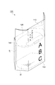
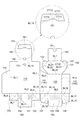
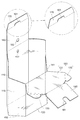
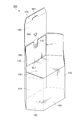
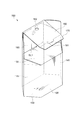
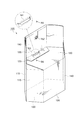
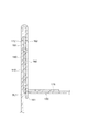
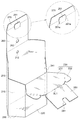
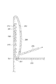
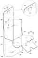
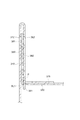
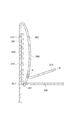
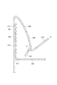
ここで、図1は、本発明の参考例である商品包装箱の外観を示す正面側斜視図であり、図2は、本発明の参考例である商品包装箱の外観を示す背面側斜視図であり、図3は、本発明の参考例である商品包装箱の展開図であり、図4は、本発明の参考例である商品包装箱の蓋板が開いた背面側斜視図であり、図5は、本発明の参考例である商品包装箱の蓋板が閉じた背面側斜視図であり、図6は、本発明の参考例である商品包装箱の正面側折り返し板が折り返された背面側斜視図であり、図7は、本発明の参考例である商品包装箱が組み立て完成した背面側斜視図であり、図8は、図7の8−8で視た係止舌片と係止スリットとの係止状態の断面図であり、図9は、図8に示す係止舌片と係止スリットとの解除動作開始状態の断面図であり、図10は、図8に示す係止舌片と係止スリットとの解除直前状態の断面図であり、図11は、図8に示す係止舌片と係止スリットとの解除直後状態の断面図である。
また、本参考例の説明において、「上」、「下」、「左」、「右」は、図1および図2に示すように組み立てられた商品包装箱を基準とした「上」、「下」、「左」、「右」、すなわち、箱吊り下げ用孔側を「上」とし、正面板へ向かって背面板から見たときの「左」、「右」である。
A product packaging box as a reference example of the present invention will be described with reference to FIGS.
Here, FIG. 1 is a front perspective view showing the appearance of a product packaging box that is a reference example of the present invention, and FIG. 2 is a rear perspective view showing the appearance of a product packaging box that is a reference example of the present invention. FIG. 3 is a developed view of a product packaging box that is a reference example of the present invention, and FIG. 4 is a rear side perspective view in which a cover plate of the product packaging box that is a reference example of the present invention is opened, FIG. 5 is a rear perspective view in which a lid of a product packaging box that is a reference example of the present invention is closed, and FIG. 6 is a front side folded plate of a product packaging box that is a reference example of the present invention. 7 is a rear perspective view, FIG. 7 is a rear perspective view in which a product packaging box which is a reference example of the present invention is assembled, and FIG. 8 is a view of a locking tongue piece viewed from 8-8 in FIG. FIG. 9 is a cross-sectional view of the engagement state with the engagement slit, and FIG. 9 is a cross-sectional view of the release operation start state of the engagement tongue piece and the engagement slit shown in FIG. 8 is a cross-sectional view of the state immediately before the release of the locking tongue piece and the locking slit shown in FIG. 8, and FIG. 11 is a cross-sectional view of the state immediately after the release of the locking tongue piece and the locking slit shown in FIG. It is.
In the description of this reference example , “top”, “bottom”, “left”, “right” are “top”, “top”, “top”, “top”, and “top” based on the product packaging box assembled as shown in FIGS. "Lower", "Left", "Right", that is, "Left", "Right" when viewed from the rear plate toward the front plate with the box suspension hole side as "Up".
まず、本発明の参考例である商品包装箱100は、図1および図2に示すように、コート紙からなる正面板110と背面板120と蓋板130とで少なくとも包囲された商品収容領域R内に商品Mを収容して陳列展示するものであって、特に、正面板110は、洗顔用石鹸からなる商品Mの付加価値を向上させるために、商品名、商品チャッチフレーズ、図柄などでデザイン性を呈し、湾曲表示面となるように配置されている。
First, as shown in FIGS. 1 and 2, a
すなわち、本発明の参考例である商品包装箱100は、図3に示すように、箱外周前方側へ膨出して湾曲する正面板110と、この正面板110に対向して箱外周後方側に配置した背面板120と、この背面板120の上側に折り曲げ線を介して連設した蓋板130と、これらの正面板110と背面板120とを折り曲げ線を介して連結する左右一対の側板140,140と、これらの正面板110と背面板120と左右一対の側板140,140の下方に折り曲げ線を介して連結された底板150と、正面板110の上側に折り曲げ線を介して連設した正面側折り返し板160と、この正面側折り返し板160の上側に折り曲げ線を介して延設したつまみ片170と、蓋板130の上側に折り曲げ線を介して延設した背面側折り返し板180とで一連に構成された蒸着紙からなり、これらの正面板110と背面板120と左右一対の側板140,140と底板150とで包囲した商品収容領域Rを形成している。
なお、本参考例の商品包装箱100で用いた蒸着紙については、アルミ蒸着したポリエチレンテレフタレートフィルムをコートカード紙の表面に被覆したものである。
That is, as shown in FIG. 3, a
In addition, about the vapor deposition paper used with the
そして、図3に示すように、上述した側壁のりしろ板115は、正面板110の右側端部で折り曲げ線となる正面板右端部折罫線BL1を介して連結され、左側板141は、正面板110の左側端部で折り曲げ線となる正面板左端部折罫線BL2を介して連結されるとともに背面板120の左側端部で折り曲げ線となる背面板右端部折罫線BL3を介して連結され、右側板142は、背面板120の右側端部で折り曲げ線となる背面板左端部折罫線BL4を介して連結され、正面側底板151は、正面板110の下端部で折り曲げ線となる正面板下端部折罫線BL5を介して連結されるとともに正面側底ベース152とこの正面側底ベース152の右端部で折り曲げ線となる正面側底ベース右端部折罫線BL7を介して連結された正面右側底ベース153とこの正面側底ベース152の左端部で折り曲げ線となる正面左側底ベース中央折罫線BL9を介して連結された正面左側底ベース154とに連結されている。
Then, as shown in FIG. 3, the side
そして、正面側底板151の正面右側底ベース153は、中央に折り曲げ線となる正面右側底ベース中央折罫線BL8を有し、正面側底板151の正面左側底ベース154は、中央に折り曲げ線となる正面左側底ベース中央折罫線BL10を有し、正面側底板151は、中央に折り曲げ線となる正面側底ベース中央折罫線BL11を有し、正面側底ベース右端部折罫線BL7と正面側底ベース左端部折罫線BL9とは、いずれも正面板110に延長され、正面板110の箱外周方向に向けて湾曲するのを助けている。
The front
また、背面板120の下側に連結された背面側底板155は、背面板120の下端部で折り曲げ線となる背面板下端部折罫線BL6を介して連結された背面側底ベース156と、この背面側底ベース156の左端部で折り曲げ線となる背面側底ベース左端部折罫線BL12および左側板141の下端部で折り曲げ線となる左側板下端部折罫線BL13のそれぞれを介して連結された背面左側底ベース157と、この背面左側底ベース157と同様に、背面側底ベース156の右端部で折り曲げ線となる背面側底ベース右端部折罫線BL15および右側板142の下端部で折り曲げ線となる右側板下端部折罫線BL16のそれぞれを介して連結された背面右側底ベース158とを有している。
そして、背面左側底ベース157は、中央に折り曲げ線となる背面右側底ベース中央折罫線BL14を有し、背面右側底ベース158は、中央に折り曲げ線である背面左側底ベース中央折罫線BL17を有している。
Further, the back
The back left
他方、蓋板130は、背面板120の上端部で折り曲げ線となる背面板上端部折罫線BL20を介して連結された蓋板本体131と、蓋板本体131の左上側端部で折り曲げ線となる蓋板左上端部折罫線BL22を介して連結された蓋板左サイドフラップ132と、蓋板本体131の右上側端部で折り曲げ線となる蓋板右上端部折罫線BL23を介して連結された蓋板右サイドフラップ133とを有している。
On the other hand, the
また、前述した正面側折り返し板160は、正面板110の上端部で折り曲げ線となる正面板上端部折罫線BL18を介して連結されている。
Further, the front side folded
前述したつまみ片170は、正面側折り返し板160の上端部で折り曲げ線となる正面側折り返し板上端部折罫線BL19を介して連結されている。
The
また、正面側折り返し板上端部折罫線BL19の中央には、つまみ片170側に切り込んだ切り欠きCT10によって係止舌片161が形成されている。
Further, a locking
そして、係止舌片161を形成する切り欠きCT10は、つまみ片170側に正面側折り返し板上端部折罫線BL19に平行に切り込んだ先端側切り欠きCT11と、先端側切り欠きCT11の右端部から正面側折り返し板上端部折罫線BL19にかけて形成されたつまみ片側右側切り欠きCT12と、先端側切り欠きCT11の左端部から正面側折り返し板上端部折罫線BL19にかけて形成されたつまみ片側左側切り欠きCT13から形成されている。
The notch CT10 forming the locking
さらに、前述した背面側折り返し板180は、蓋板本体131の上端部で折り曲げ線となる蓋板上端部折罫線BL21を介して連結されている。
また、蓋板上端部折罫線BL21には、中央に心持ち蓋板130側に切り込んだ係止スリットを形成する切り欠きCT20によって係止スリットSL1が形成されている。
Further, the above-described back
The lid plate upper end crease line BL21 is formed with a locking slit SL1 by a notch CT20 that forms a locking slit cut in the center toward the centered
そして、本参考例の商品包装箱100は、正面板110とこの正面板110の上側で折り曲げ線を介して折り返された正面側折り返し板160とが、背面側折り返し板180に形成された凹部181を介して相互に一連で挿通する箱吊り下げ用孔112,162をそれぞれ備えている。
これにより、商品包装箱100を(図示しないが)陳列展示壁などに設けた商品吊り下げ用フックなどに吊り下げて陳列する際に、箱吊り下げ用孔112,162が、正面板110と正面側折り返し板160の双方を一連で挿通するように設けられているため、商品包装箱100内に収容された商品Mが従来よりも重い吊り下げ荷重であっても十分な耐久性を発揮して、箱吊り下げ用孔112,162の破損に起因する不用意な落下も防止している。
In the
As a result, when the
次に、本発明の参考例である商品包装箱100の組み立て方を、図3乃至図7に基づいて説明する。
なお、本参考例の説明で用いる「山折り」とは、光沢紙などのコート紙の表面側が山になる折り方を意味し、「谷折り」とは、光沢紙などのコート紙の表面側が谷になる折り方を意味している。
Next, how to assemble the
The “mountain fold” used in the description of this reference example means a fold where the surface side of the coated paper such as glossy paper is a mountain, and the “valley fold” refers to the surface side of the coated paper such as glossy paper. It means how to fold into a valley.
商品包装箱100が、図7のように組み立てられる際、例えば、正面板110および側壁のりしろ115は、正面板右端部折罫線BL1で相互に鋭角となるように折り曲げられ、正面板110および左側板141は、正面板左端部折罫線BL2で相互に鋭角となるように山折りで折り曲げられる。
When the
同様に、背面板120および左側板141は、背面板右端部折罫線BL3で相互に鈍角となるように山折りで折り曲げられ、背面板120および右側板142は、背面板左端部折罫線BL4で相互に鈍角となるように折り曲げられる。
Similarly, the
そして、側壁のりしろ115は、右側板142の外側面に一例として接着剤で接着され、商品包装箱100の正面板110は、箱外周前方側へ膨出して箱外周側方側に向けて湾曲するようになる。
Then, the
正面板110および正面側底板151は、正面板下端部折罫線BL5で相互にほぼ90度となるように山折りで折り曲げられる。
正面右側底ベース153が、正面右側底ベース中央折罫線BL8で谷折りに折り曲げられた後、正面側底ベース152と正面右側底ベース153は、正面側底ベース右端部折罫線BL7で相互に鈍角となるように山折りで折り曲げられる。
正面左側底ベース154が、正面左側底ベース中央折罫線BL10で谷折りに折り曲げられた後、正面側底ベース152と正面左側底ベース154は、正面側底ベース左端部折罫線BL9で相互に鈍角となるように山折りで折り曲げられる。
続いて、正面側底ベース中央折罫線BL11で谷折りに折り曲げられる。
The
After the front
After the front
Subsequently, it is folded into a valley fold at the front side bottom base center crease line BL11.
そして、背面板120および背面側底ベース156は、背面板下端部折罫線BL6で相互に90度となるように山折りで折り曲げられる。
背面左側底ベース157が、背面右側底ベース中央折罫線BL14で谷折りに折り曲げられた後、背面側底ベース156と背面左側底ベース157は、背面側底ベース左端部折罫線BL12で相互に鈍角となるように山折りで折り曲げられるとともに、左側板141と背面左側底ベース157は、左側板下端部折罫線BL13で相互に鈍角となるように山折りで折り曲げられる。
背面右側底ベース158が、背面左側底ベース中央折罫線BL17で谷折りに折り曲げられた後、背面側底ベース156と背面右側底ベース158は、背面側底ベース右端部折罫線BL15で相互に鈍角となるように山折りで折り曲げられるとともに、右側板142と背面右側底ベース158は、右側板下端部折罫線BL16で相互に鈍角となるように山折りで折り曲げられる。
Then, the
After the back left
After the back
そして、図4のように、正面側底板151の外側面の中央に設けられた正面側底ベース中央折罫線BL11の下側半分と背面側底ベース156の外側面の上側半分とを一例として接着剤で接着され、商品包装箱100の底板150が形成される。
Then, as shown in FIG. 4, the lower half of the front side bottom base center crease line BL11 provided at the center of the outer side surface of the front side
商品収容領域R内に商品Mを収容した後、蓋板130および背面側折り返し板180は、図5のように、蓋板上端部折罫線BL21で相互にほぼ90度となるように山折りで折り曲げられる。
次に、蓋板本体131と蓋板左サイドフラップ132は、蓋板左上端部折罫線BL22で相互にほぼ90度となるように山折りで折り曲げられ、蓋板本体131と蓋板右サイドフラップ133は、蓋板右上端部折罫線BL23で相互にほぼ90度となるように山折りで折り曲げられる。
その後、図5に示すように、背面板120および蓋板本体131が、背面板上端部折罫線BL20で相互にほぼ90度となるように山折りで折り曲げられる。
After the product M is stored in the product storage region R, the
Next, the lid plate
Thereafter, as shown in FIG. 5, the
そして、図6および図7に示すように、正面側折り返し板160とつまみ片170が、正面側折り返し板上端部折罫線BL19で相互にほぼ90度となるように谷折りで折り曲げられ、正面板110と正面側折り返し板160が、正面板上端部折罫線BL18で相互にほぼ90度となるように山折りで折り曲げられる。
その後、図7に示すように、係止舌片161を係止スリットSL1に差し込んで係止することにより、商品包装箱100の組み立てが完了する。
Then, as shown in FIGS. 6 and 7, the front side folded
Then, as shown in FIG. 7, the assembly of the
そして、本参考例の商品包装箱100は、上述したように、商品収容領域R内に商品Mを収容して組み立てられることにより、背面板120より背の高い正面板110であっても正面側折り返し板160と背面側折り返し板180とが正面板110の裏面に重ね合わせられて正面板110が補強され、斜め上方から視認した場合であっても蓋板130を観せること無く商品情報のみが観易くなる。
そして、蓋板130の閉蓋時に蓋板130の背面側折り返し板180が正面板110の裏面と正面側折り返し板160との間で挟持されるとともに、つまみ片170が正面側折り返し板160とつまみ片170との折り曲げ線で蓋板130の閉蓋位置を位置決め保持し、係止舌片161を係止スリットSL1との係合状態を確実に維持するようになっている。
また、蓋板130の閉蓋時に蓋板130の背面側折り返し板180が正面板110の裏面と正面側折り返し板160との間で挟持されて重ね合わせられた状態で保持されているため、蓋板130の閉蓋時に蓋板が不用意に沈み込もうとしても正面板110の裏面と正面側折り返し板160との対向面間で接触抵抗が創出されて蓋板130の落ち込みを抑制し、特に、正面板110と背面板120と蓋板130とで少なくとも包囲された商品収容領域R内に収容される商品Mの高さ寸法が蓋板130の閉蓋位置に届くような場合には、蓋板130の不用意な落ち込みを完全に阻止する。
And as above-mentioned, the
When the
Further, when the
なお、本参考例の商品包装箱100は、商品収容領域内に商品を収容する前、もしくは、商品収容領域内から商品を取り出した後では、底板150が、正面側底ベース中央折罫線BL11を介して半分のみ接着されているため、正面板右端部折罫線BL1と正面板左端部折罫線BL2が山折りで、正面側底ベース中央折罫線BL11が谷折りでそれぞれが折り畳まれることにより、商品包装箱100を扁平かつコンパクトな状態に維持する。
In the
次に、本発明の参考例である商品包装箱100の商品収容領域R内から商品Mを取り出すなどの開蓋時に、係止舌片161と係止スリットSL1との係止状態を解除させる動作原理を、図8乃至図11に基づいて説明する。
Next, when the product M is taken out from the product storage area R of the
まず、蓋板130の閉蓋時に、蓋板130の背面側折り返し板180が、正面板110の裏面と正面側折り返し板160との間で挟持され、相互に一体となって重畳されている。
これにより、背面板120より背の高い正面板110であっても正面側折り返し板160と背面側折り返し板180とが正面板110の裏面に重ね合わせられ、正面板110が補強されている。
この時、図8に示すように、つまみ片170が、正面側折り返し板160とつまみ片170との折り曲げ線で蓋板130の閉蓋位置を位置決め保持し、係止舌片161が係止スリットSL1内に差込まれた係止状態となる。
First, when the
Thereby, even if it is the
At this time, as shown in FIG. 8, the
次に、図9に示すように、蓋板の開蓋時に人手により正面側折り返し板160を離反させるように引き上げを開始すると、正面板110と背面側折り返し板180が変形しないため、つまみ片170が、箱外周側方側に向けて湾曲する正面板110の歪で生じる内部応力の影響を受けること無く、係止舌片161を誘導して係止スリットSL1から引き出し始める。
Next, as shown in FIG. 9, when the pulling up is started so as to separate the front side folded
そして、図10に示すように、係止舌片161の正面側折り返し板上端部折罫線BL19に沿った基端部は、急激に弾性変形して係止スリットSL1から引き出される寸前の状態となる。
なお、この時でも、正面板110と背面側折り返し板180は、依然として変形していない。
And as shown in FIG. 10, the base end part along the front side folded board upper end part crease line BL19 of the latching
Even at this time, the
さらに、つまみ片170による引き出し力が所定値を超えて、図11に示すように、正面側折り返し板160が弾性変形すると、係止舌片161は、係止スリットSL1内に留まっていることができず、係止スリットSL1から引き出される。
この結果、つまみ片170が、係止舌片161と係止スリットSL1との係止状態を解除することになる。
Further, when the pulling force by the
As a result, the
このようにして得られた本発明の参考例である商品包装箱100は、箱外周前方側へ膨出して箱外周側方側に向けて湾曲する正面板110と、この正面板110の裏面に対向して箱外周後方側に配置する背の低い背面板120と、この背面板120の上側に連設して開閉する蓋板130と、これらの正面板110と背面板120と左右一対の側板140,140の下方に連結された底板150と、正面板110の上側に連設した正面側折り返し板160と、この正面側折り返し板160の上側に延設したつまみ片161と、蓋板130の上側に延設した背面側折り返し板180とを備えていることにより、湾曲表示面を備えた正面板110の優れた保形強度と形態安定性とを長期に亘って確保するとともに、スッキリとしたデザイン性の高い優れた美観を呈し、しかも、蓋板130の閉蓋時におけるつまみ片170で蓋板130の不用意な浮き上がりによる蓋外れを確実に阻止する。
A
特に、本発明の参考例である商品包装箱100では、つまみ片170を切り込んで形成した係止舌片161と、蓋板130と背面側折り返し板180との間に切り込んで形成した係止スリットSL1とを備えていることにより、従来のような係止舌片161を係止スリットSL1から直接に引き出す際に必要となる解除操作負担が著しく軽減され、つまみ片170で係止舌片161と係止スリットSL1との係止状態を簡便に解除する。
In particular, in the
以下に、本発明の第1実施例である商品包装箱200について、図12乃至図16に基づいて説明する。
ここで、図12は、本発明の第1実施例である商品包装箱の蓋板が開いた背面側斜視図であり、図13は、本発明の第1実施例における係止舌片と係止スリットとの係止状態の断面図であり、図14は、図13に示す係止舌片と係止スリットとの解除直前状態の断面図であり、図15は、図13に示す係止舌片と係止スリットとの解除直後状態の断面図である。
Below, the product packaging box 200 which is 1st Example of this invention is demonstrated based on FIG. 12 thru | or FIG.
Here, FIG. 12 is a rear perspective view in which the cover plate of the product packaging box according to the first embodiment of the present invention is opened, and FIG. 13 is related to the locking tongue piece according to the first embodiment of the present invention. FIG. 14 is a cross-sectional view showing a state immediately before the locking tongue piece and the locking slit shown in FIG. 13 are released, and FIG. 15 is a cross-sectional view showing the locking state shown in FIG. It is sectional drawing of a state immediately after cancellation | release of a tongue piece and a latching slit.
本発明の第1実施例である商品包装箱200は、前述した参考例の商品包装箱100における係止舌片161と異なる形態の係止舌片261を採用したものであって、基本的な箱形状については、参考例の商品包装箱100と共通するので、その共通する事項については、下2桁が共通する200番代の符号を付すことによりその詳しい説明を省略する。
The product packaging box 200 according to the first embodiment of the present invention employs a locking
すなわち、本発明の第1実施例である商品包装箱200は、図12に示すように、箱外周前方側へ膨出して湾曲する正面板210と、この正面板210に対向して箱外周後方側に配置した背面板220と、この背面板220の上側に折り曲げ線を介して連設した蓋板230と、これらの正面板210と背面板220とを折り曲げ線を介して連結する左右一対の側板240,240と、これらの正面板210と背面板220と左右一対の側板240,240の下方に折り曲げ線を介して連結された底板250と、正面板210の上側に折り曲げ線を介して連設した正面側折り返し板260と、この正面側折り返し板260の上側に折り曲げ線を介して延設したつまみ片270と、蓋板230の上側に折り曲げ線を介して延設した背面側折り返し板280とで一連に構成されたコート紙からなり、これらの正面板210と背面板220と左右一対の側板240,240と底板250とで包囲した商品収容領域Rを形成している。
That is, as shown in FIG. 12, the product packaging box 200 according to the first embodiment of the present invention has a
そして、図12に示すように、第2実施例の商品包装箱200が最も特徴としている係止舌片261は、つまみ片270側に正面側折り返し板上端部折罫線BL19に沿って平行に切り込んだ先端側切り欠きCT11と、先端側切り欠きCT11の右端部からつまみ片270と正面側折り返し板260との間の折り曲げ線となる正面側折り返し板上端部折罫線BL19を越えて正面側折り返し板260側に形成されたつまみ片側右側切り欠きCT12と、先端側切り欠きCT11の左端部からつまみ片270と正面側折り返し板260との間の折り曲げ線となる正面側折り返し板上端部折罫線BL19を越えて正面側折り返し板260側に形成されたつまみ片側左側切り欠きCT13とで形成されている。
Then, as shown in FIG. 12, the locking
次に、本発明の第1実施例である商品包装箱200の商品収容領域R内から商品Mを取り出すなどの開蓋時に、係止舌片261と係止スリットSL1との係止状態を解除させる動作原理を、図13乃至図15に基づいて説明する。
Next, when the product M is taken out from the product storage area R of the product packaging box 200 according to the first embodiment of the present invention, the locked state of the locking
まず、図13に示すように、蓋板230の閉蓋時に、蓋板230の背面側折り返し板280が、正面板210の裏面と正面側折り返し板260との間で挟持され、相互に一体となって重畳されている。
これにより、背面板220より背の高い正面板210であっても正面側折り返し板260と背面側折り返し板280とが正面板210の裏面に重ね合わせられ、正面板210が補強されている。
この時、図13に示すように、つまみ片270が、正面側折り返し板260とつまみ片270との折り曲げ線で蓋板230の閉蓋位置を位置決め保持し、係止舌片261が、係止スリットSL1内に差込まれた係止状態を呈している。
First, as shown in FIG. 13, when the
Thereby, even if it is the
At this time, as shown in FIG. 13, the
次に、図14に示すように、蓋板230の開蓋時に人手により正面側折り返し板260を離反させるように引き上げを開始すると、正面板210と背面側折り返し板280が変形しないため、つまみ片270が、箱外周側方側に向けて湾曲する正面板210の歪で生じる内部応力の影響を受けること無く、係止舌片261を誘導して係止スリットSL1から引き出されるようになってくる。
Next, as shown in FIG. 14, when the
そして、参考例のような係止舌片161の長さがつまみ片170と正面側折り返し板160との間の折り曲げ線を越えていない商品包装箱100よりも、係止舌片261の長さがより長くなり、係止舌片261および正面側折り返し板260の弾性変形度合いが大きくなってつまみ片270の引き上げ方向に順応し易くなり、図14に示すように、係止スリットSL1から引き出される寸前の状態になる。
なお、この時でも、正面板210と背面側折り返し板280は、依然として変形していない。
Then, the length of the locking
Even at this time, the
そして、前述したように、つまみ片270による引き出し力が所定値を超えて、正面側折り返し板260が大きく弾性変形すると、係止舌片261が係止スリットSL1に留まっていることができず、係止スリットSL1から引き出される。
その結果、つまみ片270が、係止舌片261と係止スリットSL1との係止状態を解除することになる。
As described above, when the pull-out force by the
As a result, the
また、第1実施例の商品包装箱200では、係止舌片261に左右一対で形成されたくの字状舌片側辺261a、261aが、つまみ片270と正面側折り返し板260との間の折り曲げ線と交差して相互に内向き状態に切り欠かれている。
これにより、つまみ片270のつまみ位置がつまみ片270の左右いずれかの位置に偏った場合であったり、つまみ片270の引き上げ方向が正面板210の真後ろ方向から左右いずれかの方向へ偏った場合であっても、偏った側に切り欠かれたくの字状舌片側辺261a、261aの正面側折り返し板側切り欠き部分がつまみ片270の偏った引き上げ動作に対してより一段と追従し易くなっている。
Further, in the product packaging box 200 of the first embodiment , the pair of left and right tongue-shaped
Thereby, when the knob position of the
このようにして得られた本発明の第1実施例である商品包装箱200は、前述した参考例の商品包装箱100が奏する効果に加えて、係止舌片261が、つまみ片270と正面側折り返し板260との間の折り曲げ線を越えて正面側折り返し板260側へ切り欠き形成されていることにより、前述した参考例のような係止舌片161の長さがつまみ片170と正面側折り返し板160との間の折り曲げ線を越えていない商品包装箱100よりもさらに長くなり、係止舌片261の弾性変形度合いが大きくなってつまみ片270の引き上げ方向に順応し易くなるため、開蓋のための係止舌片261と係止スリットSL1との係止解除の操作を開始する際に係止舌片261を係止スリットSL1から円滑に引き抜き解除することができる。
In the product packaging box 200 according to the first embodiment of the present invention thus obtained, the locking
しかも、係止舌片261に左右一対で形成されたくの字状舌片側辺261a、261aが、つまみ片270と正面側折り返し板260との間の折り曲げ線と交差して相互に内向き状態に切り欠かれていることにより、つまみ片270のつまみ位置がつまみ片270の左右いずれかの位置に偏った場合であったり、つまみ片270の引き上げ方向が正面板210の真後ろ方向から左右いずれかの方向へ偏った場合であっても、開蓋のための係止舌片261と係止スリットSL1との係止解除の操作を開始する際に利き手などによるつまみ片270のつまみ位置や引き上げ方向に関わること無く、係止舌片261を係止スリットSL1から円滑に引き抜き解除することができるなど、その効果は甚大である。
Moreover, the pair of left and right sides of the hook-shaped
以下、本発明の第2実施例である商品包装箱300について、図16乃至図23に基づいて説明する。
ここで、図17は、本発明の第2実施例である商品包装箱の外観を示す背面側斜視図であり、図17は、本発明の第2実施例である商品包装箱の展開図であり、図18は、本発明の第2実施例である商品包装箱の蓋板が開いた背面側斜視図であり、図19は、図16の19A−19Aで視た係止舌片と係止スリットとの係止状態の断面図であり、図20は、図16に示す係止舌片と係止スリットとの解除動作開始状態の断面図であり、図21は、図16に示す係止舌片と係止スリットとの解除直前状態の断面図であり、図22は、図16に示す切り欠き中断点が破断する状態の断面図であり、図23は、図16に示す係止舌片と係止スリットとの解除直後状態の断面図である。
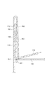
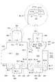
Hereinafter, a
Here, FIG. 17 is a rear perspective view showing the appearance of the product packaging box according to the second embodiment of the present invention, and FIG. 17 is an exploded view of the product packaging box according to the second embodiment of the present invention. 18 is a rear perspective view of the product packaging box according to the second embodiment of the present invention in which the cover plate is opened, and FIG. 19 is related to the locking tongue piece viewed from 19A-19A in FIG. FIG. 20 is a cross-sectional view in a state where the locking tongue piece and the locking slit shown in FIG. 16 are released, and FIG. FIG. 22 is a cross-sectional view showing a state immediately before the tongue piece and the locking slit are released, FIG. 22 is a cross-sectional view showing a state where the notch interruption point shown in FIG. 16 is broken, and FIG. It is sectional drawing of a state immediately after cancellation | release of a tongue piece and a latching slit.
本発明の第2実施例である商品包装箱300は、前述した参考例の商品包装箱100における係止舌片161および第1実施例の商品包装箱200における係止舌片261のそれぞれと異なる形態の係止舌片361を採用したものであって、基本的な箱形状については、参考例の商品包装箱100および第1実施例の商品包装箱200と共通するので、その共通する事項については、下2桁が共通する300番代の符号を付すことによりその詳しい説明を省略する。
The
すなわち、本発明の第2実施例である商品包装箱300は、図17に示すように、箱外周前方側へ膨出して湾曲する正面板310と、この正面板310に対向して箱外周後方側に配置した背面板320と、この背面板320の上側に折り曲げ線を介して連設した蓋板330と、これらの正面板310と背面板320とを折り曲げ線を介して連結する左右一対の側板340,340と、これらの正面板310と背面板320と左右一対の側板340、340の下方に折り曲げ線を介して連結された底板350と、正面板310の上側に折り曲げ線を介して連設した正面側折り返し板360と、この正面側折り返し板360の上側に折り曲げ線を介して延設したつまみ片370と、蓋板330の上側に折り曲げ線を介して延設した背面側折り返し板380とで一連に構成されたコート紙からなり、これらの正面板310と背面板320と左右一対の側板340、340と底板350とで包囲した商品収容領域Rを形成している。
That is, as shown in FIG. 17, the
そして、図17および図18に示すように、本発明の第2実施例である商品包装箱300が最も特徴としている係止舌片361は、つまみ片370側に正面側折り返し板上端部折罫線BL19に沿って平行に切り込んだ先端側切り欠きCT11と、先端側切り欠きCT11の右端部からつまみ片370と正面側折り返し板360との間の折り曲げ線となる正面側折り返し板上端部折罫線BL19を越えて正面側折り返し板360側に形成されたつまみ片側右側切り欠きCT12と、先端側切り欠きCT11の左端部からつまみ片370と正面側折り返し板360との間の折り曲げ線となる正面側折り返し板上端部折罫線BL19を越えて正面側折り返し板360側に形成されたつまみ片側左側切り欠きCT13とで形成されている。
As shown in FIGS. 17 and 18, the locking
次に、本発明の第2実施例である商品包装箱300の商品収容領域R内から商品Mを取り出すなどの開蓋時に、係止舌片361と係止スリットSL1との係止状態を解除させる動作原理を、図19乃至図23に基づいて説明する。
Next, when the product M is removed from the product storage area R of the
まず、図19に示すように、蓋板330の閉蓋時に蓋板330の背面側折り返し板380が、正面板310の裏面と正面側折り返し板360との間で挟持され、相互に一体となって重畳されている。
これにより、背面板320より背の高い正面板310であっても正面側折り返し板360と背面側折り返し板380とが正面板310の裏面に重ね合わせられ、正面板310が補強された状態になっている。
この時、図19に示すように、つまみ片370が、正面側折り返し板360とつまみ片370との折り曲げ線で蓋板330の閉蓋位置を位置決め保持し、係止舌片361は、係止スリットSL1内に差込まれた強固な係止状態を呈している。
First, as shown in FIG. 19, when the
Thereby, even if the
At this time, as shown in FIG. 19, the
次に、図20に示すように、蓋板330の開蓋時に人手によりつまみ片370を引き上げると、正面板310と背面側折り返し板380は変形しないため、箱外周側方側に向けて湾曲する正面板310の歪で生じる内部応力の影響を受けること無く、正面側折り返し板360が正面板310および背面側折り返し板380から離反するように、つまみ片370は、係止舌片361を係止スリットSL1から引き出すように誘導し始める。
Next, as shown in FIG. 20, when the
そして、図21に示すように、係止舌片361の正面側折り返し板上端部折罫線BL19に沿った基端部で急激に弾性変形して係止スリットSL1から引き出される寸前の状態になる。
なお、この時でも、正面板310と背面側折り返し板380は、依然として変形していない。
Then, as shown in FIG. 21, the base end portion along the front side folded plate upper end fold line BL19 of the locking
Even at this time, the
そして、つまみ片370による引き抜き力が所定値を超えると、つまみ片370と正面側折り返し板360との間の折り曲げ線を超えた直後の正面側折り返し板側設けた切り欠き中断点Pが破断され、図22に示すように、係止舌片361として変形可能な長さが長くなり、係止舌片361と正面側折り返し板360の弾性変形度合いが大きくなって、係止舌片361がつまみ片370の引き上げ方向に順応し易くなる。
また、つまみ片370による引き抜き力が切り欠き中断点Pを破断する際に、つまみ片370による引き抜き力は、切り欠き中断点Pで一時的に抑制されるように分散される。
When the pulling force by the
Further, when the pulling force by the
そして、図23に示すように、正面側折り返し板360がさらに弾性変形すると、係止舌片361は、係止スリットSL1に留まっていることができず、係止スリットSL1から引き出され、この結果、つまみ片370が、係止舌片361と係止スリットSL1との係止状態を解除することになる。
Then, as shown in FIG. 23, when the front-side folded
このようにして得られた本発明の第2実施例である商品包装箱300は、前述した参考例の商品包装箱100が奏する効果、すなわち、デザイン性の高い湾曲表示面を備えた正面板の優れた保形強度と形態安定性とを長期に亘って確保するとともにつまみ片370で蓋板330の不用意な浮き上がりによる蓋外れを確実に阻止し、従来のような係止舌片を係止スリットから直接に引き出す際に必要となる解除操作負担が著しく軽減され、つまみ片370で係止舌片361と係止スリットSL1との係止状態を簡便に解除するという効果に加えて、係止舌片361が、つまみ片370と正面側折り返し板360との間の折り曲げ線となる正面側折り返し板上端部折罫線BL19を超えた直後の正面側折り返し板360側の切り欠き中断点Pを除いて、正面側折り返し板360側へ切り欠き形成されていることにより、つまみ片370による引き抜き力が一定以上になると、先に切り欠き中断点Pが破断されて係止舌片361として変形可能な長さが長くなり、係止舌片361の弾性変形度合いが大きくなってつまみ片370の引き上げ方向に順応し易くなるため、開蓋のための係止舌片361と係止スリットSL1との係止解除の操作を開始する際に係止舌片361を係止スリットSL1から円滑に引き抜くことができるとともに、この切り欠き中断点Pの破断により、蓋板330を破損することなく係止舌片361を係止スリットSL1から円滑に引き抜き、しかも、商品包装箱300を出荷した後に開蓋された事実を簡便に確認することもできる。
The
さらに、係止舌片361に左右一対で形成されたくの字状舌片側辺361a、361aが、つまみ片370と正面側折り返し板360との間の折り曲げ線と交差して相互に内向き状態に切り欠かれていることにより、つまみ片370のつまみ位置がつまみ片370の左右いずれかの位置に偏った場合であったり、つまみ片370の引き上げ方向が正面板310の真後ろ方向から左右いずれかの方向へ偏った場合であっても、開蓋のための係止舌片361と係止スリットSL1との係止解除の操作を開始する際に利き手などによるつまみ片370のつまみ位置や引き上げ方向に関わること無く、係止舌片361を係止スリットSL1から円滑に引き抜き解除することができるなど、その効果は甚大である。
Further, the pair of left and right sides of the hook-shaped tongue piece 361a, 361a formed on the locking
100、200、300・・・商品包装箱
110、210、310・・・正面板
112、212、312・・・箱吊り下げ用孔
115、215、315・・・側壁のりしろ板
120、220、320・・・背面板
130、230、330・・・蓋板
131、231、331・・・蓋板本体
132、232、332・・・蓋板左サイドフラップ
133、233、333・・・蓋板右サイドフラップ
140、240、340・・・側板
141、241、341・・・左側板
142、242、342・・・右側板
150、250、350・・・底板
151、251、351・・・正面側底板
152、252、352・・・正面側底ベース
153、253、353・・・正面右側底ベース
154、254、354・・・正面左側底ベース
155、255、355・・・背面側底板
156、256、356・・・背面側底ベース
157、257、357・・・背面左側底ベース
158、258、358・・・背面右側底ベース
160、260、360・・・正面側折り返し板
161、261、361・・・係止舌片
261a ・・・くの字状舌片側辺
162、262、362・・・箱吊り下げ用孔
170、270、370・・・つまみ片
180、280、380・・・背面側折り返し板
181、281、381・・・凹部
M ・・・商品
R ・・・商品収容領域
SL1 ・・・係止スリット
P ・・・切り欠き中断点
BL1 ・・・正面板右端部折罫線
BL2 ・・・正面板左端部折罫線
BL3 ・・・背面板右端部折罫線
BL4 ・・・背面板左端部折罫線
BL5 ・・・正面板下端部折罫線
BL6 ・・・背面板下端部折罫線
BL7 ・・・正面側底ベース右端部折罫線
BL8 ・・・正面右側底ベース中央折罫線
BL9 ・・・正面側底ベース左端部折罫線
BL10・・・正面左側底ベース中央折罫線
BL11・・・正面側底ベース中央折罫線
BL12・・・背面側底ベース左端部折罫線
BL13・・・左側板下端部折罫線
BL14・・・背面右側底ベース中央折罫線
BL15・・・背面側底ベース右端部折罫線
BL16・・・右側板下端部折罫線
BL17・・・背面左側底ベース中央折罫線
BL18・・・正面板上端部折罫線
BL19・・・正面側折り返し板上端部折罫線
BL20・・・背面板上端部折罫線
BL21・・・蓋板上端部折罫線
BL22・・・蓋板左上端部折罫線
BL23・・・蓋板右上端部折罫線
CT10・・・切り欠き
CT11・・・先端側切り欠き
CT12・・・つまみ片側右側切り欠き
CT13・・・つまみ片側左側切り欠き
CT20・・・切り欠き
100, 200, 300 ...
115, 215, 315...
120, 220, 320 ... back
Claims (4)
前記つまみ片を切り込むとともに前記つまみ片と正面側折り返し板との間の折り曲げ線を越えて正面側折り返し板側へ切り込んで形成して前記正面側折り返し板の上側に設けた折り曲げ線から前記蓋板に向けて起立する係止舌片と、
前記蓋板と背面側折り返し板との間の折り曲げ線に沿って切り込んで形成して前記係止舌片を差し込み係止する係止スリットとを備え、
前記つまみ片によって前記係止舌片と係止スリットとの係止状態を解除することを特徴とする商品包装箱。 A front plate that bulges toward the front side of the box and curves toward the outer side of the box, a short back plate that faces the back side of the front plate and is placed on the rear side of the box, and bends above the back plate. A lid plate that is connected and opened via a wire, a front side folded plate that is connected to the upper side of the front plate via a folding line, and a knob piece that is extended above the front side folded plate via a folding line And a back side folded plate extending above the lid plate via a folding line, and a product packaging box forming a product containing area surrounded at least by the front plate, the back plate and the lid plate. And
The lid plate is formed from the folding line formed on the upper side of the front side folding plate formed by cutting the knob piece and cutting to the front side folding plate side beyond the folding line between the knob piece and the front side folding plate. A locking tongue that stands up toward
A locking slit that is formed by cutting along a fold line between the lid plate and the back side folding plate and inserting and locking the locking tongue piece;
A product packaging box, wherein the locking state between the locking tongue piece and the locking slit is released by the knob piece.
前記つまみ片を切り込むとともに前記つまみ片と正面側折り返し板との間の折り曲げ線を越えた直後の正面側折り返し板側の切り欠き中断点を除いて正面側折り返し板側へ切り込んで形成して前記正面側折り返し板の上側に設けた折り曲げ線から前記蓋板に向けて起立する係止舌片と、
前記蓋板と背面側折り返し板との間の折り曲げ線に沿って切り込んで形成して前記係止舌片を差し込み係止する係止スリットとを備え、
前記つまみ片によって前記係止舌片と係止スリットとの係止状態を解除することを特徴とする商品包装箱。 A front plate that bulges toward the front side of the box and curves toward the outer side of the box, a short back plate that faces the back side of the front plate and is placed on the rear side of the box, and bends above the back plate. A lid plate that is connected and opened via a wire, a front side folded plate that is connected to the upper side of the front plate via a folding line, and a knob piece that is extended above the front side folded plate via a folding line And a back side folded plate extending above the lid plate via a folding line, and a product packaging box forming a product containing area surrounded at least by the front plate, the back plate and the lid plate. And
The knob piece is cut and formed by cutting to the front folded plate side except for a notch interruption point on the front folded plate side immediately after the folding line between the knob piece and the front folded plate is exceeded. A locking tongue that stands up from a fold line provided on the upper side of the front side folding plate toward the lid plate;
A locking slit that is formed by cutting along a fold line between the lid plate and the back side folding plate and inserting and locking the locking tongue piece;
A product packaging box, wherein the locking state between the locking tongue piece and the locking slit is released by the knob piece.
前記つまみ片を少なくとも切り込んで形成して前記正面側折り返し板の上側に設けた折り曲げ線から前記蓋板に向けて起立する係止舌片と、
前記蓋板と背面側折り返し板との間の折り曲げ線に沿って切り込んで形成して前記係止舌片を差し込み係止する係止スリットとを備え、
前記係止舌片に左右一対で形成されたくの字状舌片側辺が、前記つまみ片と正面側折り返し板との間の折り曲げ線と交差して相互に内向き状態に切り欠かれ、
前記つまみ片によって前記係止舌片と係止スリットとの係止状態を解除することを特徴とする商品包装箱。 A front plate that bulges toward the front side of the box and curves toward the outer side of the box, a short back plate that faces the back side of the front plate and is placed on the rear side of the box, and bends above the back plate. A lid plate that is connected and opened via a wire, a front side folded plate that is connected to the upper side of the front plate via a folding line, and a knob piece that is extended above the front side folded plate via a folding line And a back side folded plate extending above the lid plate via a folding line, and a product packaging box forming a product containing area surrounded at least by the front plate, the back plate and the lid plate. And
A locking tongue piece that is formed by cutting at least the knob piece and is raised from a fold line provided on the upper side of the front side folding plate toward the lid plate;
A locking slit that is formed by cutting along a fold line between the lid plate and the back side folding plate and inserting and locking the locking tongue piece;
The pair of left and right sides of the tongue-shaped tongue formed on the locking tongue piece are cut out in an inward state with respect to each other, intersecting with a fold line between the knob piece and the front folded plate,
A product packaging box, wherein the locking state between the locking tongue piece and the locking slit is released by the knob piece.
The front plate and the front side folded plate folded back via a folding line on the upper side of the front plate are each provided with a box suspension hole through which the front plate and the front side folded plate are inserted in series. The product packaging box according to claim 3.
Priority Applications (1)
| Application Number | Priority Date | Filing Date | Title |
|---|---|---|---|
| JP2015050378A JP6564589B2 (en) | 2015-03-13 | 2015-03-13 | Product packaging box |
Applications Claiming Priority (1)
| Application Number | Priority Date | Filing Date | Title |
|---|---|---|---|
| JP2015050378A JP6564589B2 (en) | 2015-03-13 | 2015-03-13 | Product packaging box |
Publications (2)
| Publication Number | Publication Date |
|---|---|
| JP2016169038A JP2016169038A (en) | 2016-09-23 |
| JP6564589B2 true JP6564589B2 (en) | 2019-08-21 |
Family
ID=56982130
Family Applications (1)
| Application Number | Title | Priority Date | Filing Date |
|---|---|---|---|
| JP2015050378A Active JP6564589B2 (en) | 2015-03-13 | 2015-03-13 | Product packaging box |
Country Status (1)
| Country | Link |
|---|---|
| JP (1) | JP6564589B2 (en) |
Family Cites Families (3)
| Publication number | Priority date | Publication date | Assignee | Title |
|---|---|---|---|---|
| JPH063784Y2 (en) * | 1988-03-07 | 1994-02-02 | 凸版印刷株式会社 | Storage box |
| JP2008308172A (en) * | 2007-06-12 | 2008-12-25 | Tombow Pencil Co Ltd | Packaging box |
| JP2011051630A (en) * | 2009-09-02 | 2011-03-17 | Kyodo Printing Co Ltd | Carton with hanging hook |
-
2015
- 2015-03-13 JP JP2015050378A patent/JP6564589B2/en active Active
Also Published As
| Publication number | Publication date |
|---|---|
| JP2016169038A (en) | 2016-09-23 |
Similar Documents
| Publication | Publication Date | Title |
|---|---|---|
| US20250091759A1 (en) | Tamper-evident box | |
| US11731800B2 (en) | Method of using a locking box | |
| CN102232040B (en) | A display carton for a plurality of products and blank thereof | |
| US20150344216A1 (en) | Folding cupcake box | |
| US20110253775A9 (en) | Display carton for a plurality of products | |
| CN106458360B (en) | box | |
| US4230259A (en) | Self-locking cartons | |
| EP3317194B1 (en) | Display carton | |
| JP6564589B2 (en) | Product packaging box | |
| JP2014055031A (en) | Wiper blade packaging container | |
| US10625900B2 (en) | Foldable packaging system | |
| US2181482A (en) | Fibroid case | |
| JP6758705B2 (en) | Tamper-proof packaging box | |
| JP6424017B2 (en) | Junction box and packaging container provided with the same | |
| JP6424516B2 (en) | Consolidated packaging box | |
| KR20230001958U (en) | paper box with foldable cover for delivery | |
| KR20110121268A (en) | Packaging box in which cover plates are folded simultaneously with one touch | |
| JP2001315762A (en) | Goods storage box | |
| JP3100043U (en) | Towel cosmetic box and storage box | |
| JP4242524B2 (en) | Packaging box | |
| US20050061702A1 (en) | Napkin holder | |
| JP2002059918A (en) | Product storage box | |
| JP6311984B2 (en) | Packaging box | |
| JP2019524574A (en) | Packaging box with an opening in the wall | |
| EP1848642B1 (en) | Device for containing and/or holding objects |
Legal Events
| Date | Code | Title | Description |
|---|---|---|---|
| A621 | Written request for application examination |
Free format text: JAPANESE INTERMEDIATE CODE: A621 Effective date: 20180115 |
|
| A977 | Report on retrieval |
Free format text: JAPANESE INTERMEDIATE CODE: A971007 Effective date: 20180913 |
|
| A131 | Notification of reasons for refusal |
Free format text: JAPANESE INTERMEDIATE CODE: A131 Effective date: 20181023 |
|
| A521 | Request for written amendment filed |
Free format text: JAPANESE INTERMEDIATE CODE: A523 Effective date: 20181221 |
|
| A521 | Request for written amendment filed |
Free format text: JAPANESE INTERMEDIATE CODE: A523 Effective date: 20181225 |
|
| A131 | Notification of reasons for refusal |
Free format text: JAPANESE INTERMEDIATE CODE: A131 Effective date: 20190416 |
|
| A521 | Request for written amendment filed |
Free format text: JAPANESE INTERMEDIATE CODE: A523 Effective date: 20190614 |
|
| TRDD | Decision of grant or rejection written | ||
| A01 | Written decision to grant a patent or to grant a registration (utility model) |
Free format text: JAPANESE INTERMEDIATE CODE: A01 Effective date: 20190709 |
|
| A61 | First payment of annual fees (during grant procedure) |
Free format text: JAPANESE INTERMEDIATE CODE: A61 Effective date: 20190729 |
|
| R150 | Certificate of patent or registration of utility model |
Ref document number: 6564589 Country of ref document: JP Free format text: JAPANESE INTERMEDIATE CODE: R150 |
|
| R250 | Receipt of annual fees |
Free format text: JAPANESE INTERMEDIATE CODE: R250 |