JP6564572B2 - X-ray equipment - Google Patents
X-ray equipment Download PDFInfo
- Publication number
- JP6564572B2 JP6564572B2 JP2015004708A JP2015004708A JP6564572B2 JP 6564572 B2 JP6564572 B2 JP 6564572B2 JP 2015004708 A JP2015004708 A JP 2015004708A JP 2015004708 A JP2015004708 A JP 2015004708A JP 6564572 B2 JP6564572 B2 JP 6564572B2
- Authority
- JP
- Japan
- Prior art keywords
- collimator
- ray
- sample stage
- measurement
- multilayer structure
- Prior art date
- Legal status (The legal status is an assumption and is not a legal conclusion. Google has not performed a legal analysis and makes no representation as to the accuracy of the status listed.)
- Active
Links
- 238000005259 measurement Methods 0.000 claims description 66
- 238000000235 small-angle X-ray scattering Methods 0.000 claims description 34
- 238000000034 method Methods 0.000 claims description 16
- 238000002441 X-ray diffraction Methods 0.000 claims description 6
- 238000004458 analytical method Methods 0.000 claims description 3
- 239000000843 powder Substances 0.000 description 6
- 230000005855 radiation Effects 0.000 description 6
- 230000003287 optical effect Effects 0.000 description 5
- 230000000052 comparative effect Effects 0.000 description 3
- 238000002310 reflectometry Methods 0.000 description 3
- 238000000691 measurement method Methods 0.000 description 2
- 238000010606 normalization Methods 0.000 description 2
- 239000011148 porous material Substances 0.000 description 2
- 238000012512 characterization method Methods 0.000 description 1
- 230000001419 dependent effect Effects 0.000 description 1
- 238000013461 design Methods 0.000 description 1
- 238000011161 development Methods 0.000 description 1
- 230000018109 developmental process Effects 0.000 description 1
- 230000000694 effects Effects 0.000 description 1
- 238000002474 experimental method Methods 0.000 description 1
- 230000002452 interceptive effect Effects 0.000 description 1
- 239000011159 matrix material Substances 0.000 description 1
- 239000002245 particle Substances 0.000 description 1
Images


Classifications
-
- G—PHYSICS
- G01—MEASURING; TESTING
- G01N—INVESTIGATING OR ANALYSING MATERIALS BY DETERMINING THEIR CHEMICAL OR PHYSICAL PROPERTIES
- G01N23/00—Investigating or analysing materials by the use of wave or particle radiation, e.g. X-rays or neutrons, not covered by groups G01N3/00 – G01N17/00, G01N21/00 or G01N22/00
- G01N23/20—Investigating or analysing materials by the use of wave or particle radiation, e.g. X-rays or neutrons, not covered by groups G01N3/00 – G01N17/00, G01N21/00 or G01N22/00 by using diffraction of the radiation by the materials, e.g. for investigating crystal structure; by using scattering of the radiation by the materials, e.g. for investigating non-crystalline materials; by using reflection of the radiation by the materials
- G01N23/201—Investigating or analysing materials by the use of wave or particle radiation, e.g. X-rays or neutrons, not covered by groups G01N3/00 – G01N17/00, G01N21/00 or G01N22/00 by using diffraction of the radiation by the materials, e.g. for investigating crystal structure; by using scattering of the radiation by the materials, e.g. for investigating non-crystalline materials; by using reflection of the radiation by the materials by measuring small-angle scattering
-
- G—PHYSICS
- G01—MEASURING; TESTING
- G01N—INVESTIGATING OR ANALYSING MATERIALS BY DETERMINING THEIR CHEMICAL OR PHYSICAL PROPERTIES
- G01N23/00—Investigating or analysing materials by the use of wave or particle radiation, e.g. X-rays or neutrons, not covered by groups G01N3/00 – G01N17/00, G01N21/00 or G01N22/00
- G01N23/20—Investigating or analysing materials by the use of wave or particle radiation, e.g. X-rays or neutrons, not covered by groups G01N3/00 – G01N17/00, G01N21/00 or G01N22/00 by using diffraction of the radiation by the materials, e.g. for investigating crystal structure; by using scattering of the radiation by the materials, e.g. for investigating non-crystalline materials; by using reflection of the radiation by the materials
- G01N23/207—Diffractometry using detectors, e.g. using a probe in a central position and one or more displaceable detectors in circumferential positions
-
- G—PHYSICS
- G21—NUCLEAR PHYSICS; NUCLEAR ENGINEERING
- G21K—TECHNIQUES FOR HANDLING PARTICLES OR IONISING RADIATION NOT OTHERWISE PROVIDED FOR; IRRADIATION DEVICES; GAMMA RAY OR X-RAY MICROSCOPES
- G21K1/00—Arrangements for handling particles or ionising radiation, e.g. focusing or moderating
- G21K1/02—Arrangements for handling particles or ionising radiation, e.g. focusing or moderating using diaphragms, collimators
- G21K1/04—Arrangements for handling particles or ionising radiation, e.g. focusing or moderating using diaphragms, collimators using variable diaphragms, shutters, choppers
- G21K1/046—Arrangements for handling particles or ionising radiation, e.g. focusing or moderating using diaphragms, collimators using variable diaphragms, shutters, choppers varying the contour of the field, e.g. multileaf collimators
Landscapes
- Chemical & Material Sciences (AREA)
- Physics & Mathematics (AREA)
- General Physics & Mathematics (AREA)
- Immunology (AREA)
- Life Sciences & Earth Sciences (AREA)
- Analytical Chemistry (AREA)
- Biochemistry (AREA)
- General Health & Medical Sciences (AREA)
- Crystallography & Structural Chemistry (AREA)
- Health & Medical Sciences (AREA)
- Pathology (AREA)
- Spectroscopy & Molecular Physics (AREA)
- Engineering & Computer Science (AREA)
- General Engineering & Computer Science (AREA)
- High Energy & Nuclear Physics (AREA)
- Analysing Materials By The Use Of Radiation (AREA)
Description
本発明は、X線回折装置及びX線回折測定方法に関する。 The present invention relates to an X-ray diffraction apparatus and an X-ray diffraction measurement method.
X線回折装置は、様々な状況及び用途において用いられている。 X-ray diffractometers are used in a variety of situations and applications.
一の用途は粉末試料の測定である。 One application is the measurement of powder samples.
特に、小角X線散乱−SAXS-は、小角でのX線散乱−たとえば1nm〜100nmであり得る長さスケールでの試料の構造に対応する−を測定するのに用いられ得る。SAXSで用いられる小角(2θ)は典型的には5°未満である。角度が小さければ小さいほど、長さスケールが大きくなる。結果として粒径又は有孔性材料中の孔のサイズも大きくなり得る。 In particular, small-angle X-ray scattering—SAXS—can be used to measure small-angle X-ray scattering—corresponding to the structure of a sample on a length scale that can be, for example, 1 nm to 100 nm. The small angle (2θ) used in SAXS is typically less than 5 °. The smaller the angle, the larger the length scale. As a result, the particle size or pore size in the porous material can also be increased.
X線ビームは典型的には、非常に細いビーム(線)又は粉末試料へ導かれる小さなスポットへコリメートされる。小角で試料によって散乱されるX線はX線検出器によって検出される。 The x-ray beam is typically collimated into a very narrow beam (line) or a small spot directed to the powder sample. X-rays scattered by the sample at a small angle are detected by an X-ray detector.
一部のSAXS法では、擬単色放射線で作業することが重要である。その理由は、擬単色放射線は、(より精度の高いデータを得るため)データの規格化の可能性を改善するからである。規格化は、試料ホルダからのバックグラウンドが試料の信号から差し引かれるときに実行されて良い。第1測定が、試料ホルダ内の試料を測定することによって実行される。第2測定が、試料ホルダのみを測定することによって実行される。結果はスケーリングされて規格化される。第2測定の結果は第1測定結果から差し引かれることで、試料からの結果の純粋な寄与が得られる。 In some SAXS methods, it is important to work with quasi-monochromatic radiation. This is because quasi-monochromatic radiation improves the possibility of data normalization (to obtain more accurate data). Normalization may be performed when the background from the sample holder is subtracted from the sample signal. The first measurement is performed by measuring the sample in the sample holder. A second measurement is performed by measuring only the sample holder. The result is scaled and normalized. The result of the second measurement is subtracted from the first measurement result to obtain a pure contribution of the result from the sample.
正確なSAXS測定のためには、コリメータは、SAXS測定の結果に影響を及ぼす恐れのあるさらなる妨害散乱放射線を生成しないことが重要である。 For accurate SAXS measurements, it is important that the collimator does not generate additional interfering scattered radiation that can affect the results of the SAXS measurement.
正規に用いられた一の方法は、X線管からの強度のほとんどを阻止して非常に細いビーム路だけを残して試料に衝突させる高研磨コリメーションブロックを用いることだった。高品質コリメーションブロックが、さらなる散乱を防止するのに必要だった。 One form of regular use was to use a highly polished collimation block that blocks most of the intensity from the x-ray tube and leaves only a very narrow beam path to impact the sample. A high quality collimation block was necessary to prevent further scattering.
SAXS用の最近の装置は、1次元又は2次元の多層プレコリメータを用いて、たとえばスリット又はピンホールで構成される最終コリメータの前方でプレコリメーションを起こした。各異なる型のコリメータ(1D又は2D)は、小角(2θ)での測定が可能で、かつ、SAXSの測定結果に影響を及ぼす恐れがある妨害散乱放射線が除去されることを保証する。 Recent devices for SAXS have used pre-collimation in front of the final collimator consisting of a slit or pinhole, for example, using a one-dimensional or two-dimensional multi-layer pre-collimator. Each different type of collimator (1D or 2D) ensures that small-angle (2θ) measurements are possible and that disturbing scattered radiation that can affect the SAXS measurement results is eliminated.
1次元又は2次元の多層プレコリメータによるプレコリメーションは2つの効果を有する。第1には、プレコリメーションはX線ビームを単色とみなす。より重要なことは、プレコリメーションは、X線管からのX線ビームを収集及び再案内することによって、そのX線ビームがコリメータに到達する前にそのX線ビームの強度を増大させるように機能することである。プレコリメータは通常、1次元コリメーション又は2次元コリメーション用の放物形状又は楕円形状のミラーを用いる。 Pre-collimation with a one-dimensional or two-dimensional multilayer pre-collimator has two effects. First, pre-collimation regards the X-ray beam as a single color. More importantly, pre-collimation functions to increase the intensity of the x-ray beam before it reaches the collimator by collecting and re-guiding the x-ray beam from the x-ray tube It is to be. A pre-collimator typically uses a parabolic or elliptical mirror for one-dimensional or two-dimensional collimation.
SAXS測定を実行する装置は市販されている。 Devices that perform SAXS measurements are commercially available.
X線回折装置の購入者は、異なる測定を実行するために多数の装置部品を購入しなければならないことも、異なる測定手法用に装置を再設定する大変な作業を行わなければならないことも望んでいない。従って最小の再設定で他の種類の測定を実行できる装置を供すること、特にSAXSで用いられ得る装置と同一の装置を用いることは大きな利点である。 X-ray diffractometer purchasers also want to purchase a large number of instrument parts to perform different measurements, and to do the hard work of reconfiguring the instrument for different measurement techniques. Not. It is therefore a great advantage to provide a device that can perform other types of measurements with minimal resetting, in particular using the same device that can be used with SAXS.
本発明の第1態様によると、X線回折装置が供される。当該装置は、焦点を有するX線源、試料台、前記焦点から前記試料台へX線を案内するため、前記焦点と前記試料台との間に設けられた平坦な傾斜多層構造、前記試料台上に載置された試料からのX線を検出するX線検出器、さらに前記X線源と前記試料台との間に設けられたコリメータを有する。前記コリメータは、ブラッグ・ブレンターノ測定用の広い実効開口部又はSAXS用の狭い実効開口部に調節可能である。 According to a first aspect of the present invention, an X-ray diffractometer is provided. The apparatus includes an X-ray source having a focal point, a sample stage, a flat inclined multilayer structure provided between the focal point and the sample stage for guiding X-rays from the focal point to the sample stage, and the sample stage An X-ray detector for detecting X-rays from a sample placed thereon, and a collimator provided between the X-ray source and the sample stage are provided. The collimator can be adjusted to a wide effective opening for Bragg Brentano measurement or a narrow effective opening for SAXS.
平坦な傾斜多層構造は、複数の層と平坦な表面を有する。前記平坦な傾斜多層構造の機能は、発散光学系のモノクロメータとしての機能である。たとえばX線源から入射発散X線ビームは、平坦な傾斜多層構造へ入射し、かつ、前記入射発散X線ビームと同一の発散を有するように単色光を反射させる。 A flat gradient multilayer structure has multiple layers and a flat surface. The function of the flat inclined multilayer structure is a function as a monochromator of a divergent optical system. For example, an incident divergent X-ray beam from an X-ray source is incident on a flat tilted multilayer structure and reflects monochromatic light so as to have the same divergence as the incident divergent X-ray beam.
よって平坦な傾斜多層構造はこれまで、発散ビームが必要な用途において用いられてきた。他方SAXSは、発散が(ほとんど)ないように可能な限り正確にコリメートされたビームを必要とする。よってSAXS装置内での平坦な傾斜多層構造の利用は、本願発明者が知る限り提案されてこなかった。 Thus, flat gradient multilayer structures have been used in applications where divergent beams are required. SAXS, on the other hand, requires a collimated beam as accurately as possible so that there is (almost) no divergence. Therefore, the use of a flat inclined multilayer structure in the SAXS apparatus has not been proposed as far as the inventors of the present application know.
このような明白な短所にもかかわらず、本願発明者等は、平坦な傾斜多層構造を用いて実行されるSAXS測定が、後述するように従来装置を用いたSAXS測定と同程度に良好で、かつ、装置は、ブラッグ・ブレンターノ測定の結果をさらに向上及び高品質にすることができることを発見した。 In spite of such obvious shortcomings, the inventors of the present application, SAXS measurement performed using a flat inclined multilayer structure is as good as SAXS measurement using a conventional apparatus, as described later, And the device has discovered that the results of Bragg Brentano measurements can be further improved and of higher quality.
前記狭い実効開口部は、SAXSに用いられて良く、かつ、さらに反射率測定又は前記狭い実効開口部を用いた他の測定−たとえば不均一試料上での微少スポット解析−に用いられても良い。 The narrow effective aperture may be used for SAXS, and may also be used for reflectance measurements or other measurements using the narrow effective aperture, such as micro spot analysis on a non-uniform sample. .
SAXS又は他の測定用の前記狭い実効開口部は、0.07°−好適には0.05°−を超えないビーム発散角を実現し得る。ブラッグ・ブレンターノ測定用の前記広い実効開口部は一般的に、0.1°−好適には0.15°−を超えるビーム発散角を実現し得る。 The narrow effective aperture for SAXS or other measurements can achieve a beam divergence angle not exceeding 0.07 ° -preferably 0.05 °-. The wide effective aperture for Bragg-Brentano measurement can generally achieve a beam divergence angle exceeding 0.1 ° -preferably 0.15 °-.
本発明のさらなる発展型は従属請求項に記載されている。 Further developments of the invention are described in the dependent claims.
好適実施例では、複数の種類の測定を実行するのに、第2面上でのさらなる光学系−たとえば−の追加又は第1面上での光学系の交換を必要としない。 In the preferred embodiment, performing additional types of measurements does not require the addition of additional optical systems on the second surface, for example, or replacement of optical systems on the first surface.
前記コリメータは、前記平坦な傾斜多層構造と前記試料台との間に設けられて良い。これにより、前記X線源からのX線が、広範囲の角度で前記平坦な傾斜多層構造上に衝突することが可能となる。その理由は、前記平坦な傾斜多層構造を前記X線源からある距離に保つコリメータが前記平坦な傾斜多層構造と前記X線源との間に存在しないためである。あるいはその代わりに前記コリメータは前記X線源と前記平坦な傾斜多層構造との間に設けられても良い。 The collimator may be provided between the flat inclined multilayer structure and the sample stage. Thereby, X-rays from the X-ray source can collide with the flat inclined multilayer structure at a wide range of angles. The reason is that there is no collimator between the flat inclined multilayer structure and the X-ray source to keep the flat inclined multilayer structure at a certain distance from the X-ray source. Alternatively, the collimator may be provided between the X-ray source and the flat gradient multilayer structure.
前記コリメータは、1次元コリメータ−たとえば幅が可変のスリット開口部−であって良い。 The collimator may be a one-dimensional collimator, for example a slit opening with a variable width.
前記コリメータは、可変幅及び/又は高さの開口部を有する2次元コリメータであっても良い。 The collimator may be a two-dimensional collimator having an opening having a variable width and / or height.
当該装置はさらに、前記平坦な傾斜多層構造と前記試料台の間に配置された他の平坦、放物形状、楕円形状、又は双曲形状の多層構造を有して良い。 The apparatus may further comprise another flat, parabolic, elliptical, or hyperbolic multilayer structure disposed between the flat inclined multilayer structure and the sample stage.
前記X線検出器は位置感受性を有する検出器であって良い。前記位置感受性を有する検出器は、一方向での位置を検出する1次元検出器又は2次元マトリックス内に配置される複数の画素を有する2次元検出器であって良い。 The X-ray detector may be a position sensitive detector. The position-sensitive detector may be a one-dimensional detector that detects a position in one direction or a two-dimensional detector having a plurality of pixels arranged in a two-dimensional matrix.
他の態様では、本発明は、請求項1乃至9のいずれか一項に記載の装置の操作方法に関する。当該方法は、前記コリメータを広い実効開口部に調節してブラッグ・ブレンターノ配置での測定を実行する段階;及び、前記コリメータを狭い実効開口部に調節して小角X線散乱-SAXS-測定を実行する段階を有する。 In another aspect, the invention relates to a method for operating a device according to any one of claims 1 to 9. The method includes adjusting the collimator to a wide effective aperture to perform measurements in a Bragg-Brentano configuration; and adjusting the collimator to a narrow effective aperture to perform small-angle X-ray scattering-SAXS-measurement. Having a stage to do.
当該方法はさらに、狭い実効開口部を用いて反射率測定を実行する段階を有して良い。 The method may further comprise performing reflectivity measurements using a narrow effective aperture.
ここで本発明の例を添付図面を参照しながら説明する。 An example of the present invention will now be described with reference to the accompanying drawings.
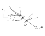
図1を参照すると、本発明による装置は、X線源2、粉末試料6を載置する試料台4、及び、X線検出器20を有する。
Referring to FIG. 1, the apparatus according to the present invention includes an
平坦な傾斜多層構造8が、X線源2と試料台4との間のビーム10のビーム路中に供される。
A flat
X線源の線状焦点12は発散X線ビーム10を生成する。発散X線ビーム10は平坦な傾斜多層構造8へ入射する。平坦な傾斜多層構造8は、単色光を試料台4上に試料6へ向かうように反射させる。平坦な傾斜多層構造8は発散ビーム10を変化させないので、試料は明確な焦点14から照射される。
A linear
当該装置はまた、X線源2と試料台4との間の入射ビーム路10中にコリメータ16をも有する。
The apparatus also has a
SAXS測定を実行するため、X線源2、試料台4上の試料6、及び検出器20は、図1のように配置される。ビーム10はコリメータ16によって、狭い範囲の角度−0.07°を超えない−に制限される。明確な焦点14、試料6、及び検出器20は、略直線上に配置される。検出器は、試料6による小角散乱を検出するのに用いられる。
In order to perform SAXS measurement, the
その後測定は試料6のない試料台4と試料ホルダだけの状態で繰り返される。その結果は規格化される。繰り返された測定結果は第1測定から差し引かれることで、試料6の散乱が計算される。 Thereafter, the measurement is repeated with only the sample table 4 without the sample 6 and the sample holder. The result is normalized. The scattered measurement of the sample 6 is calculated by subtracting the repeated measurement result from the first measurement.
コリメータ16は具体的に、平坦な傾斜多層構造8と試料台4との間に配置されるスリットコリメータであって良い。スリットは、広い範囲のX線が通過する第1状態(図2の実線)とX線を狭い角度範囲に制限する第2状態(図2の点線)との間で広範に調節されて良い。
Specifically, the
係るコリメータは入射X線をコリメートして良い。その結果コリメートされたビームは、SAXS測定又は反射率測定に用いられて良い。 Such a collimator may collimate incident X-rays. As a result, the collimated beam can be used for SAXS or reflectance measurements.
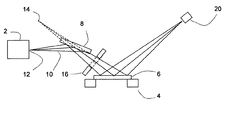
ブラッグ・ブレンターノ測定を可能にするため、幾何学的配置は、試料台4と検出器20の位置を回転させることによって図2に表された幾何学的配置に再設定される。
In order to allow Bragg Brentano measurements, the geometry is reset to the geometry represented in FIG. 2 by rotating the position of the sample stage 4 and
コリメータ16は、図2の実線によって表されている広い開口部に調節される。図1の狭いスリットは、比較用に図2では点線を用いて表されている。
The
ブラッグ・ブレンターノ幾何学配置を保証するため、明確な焦点14とX線検出器20は、以降の半径で表されるように、試料から同一距離に配置される。
To ensure the Bragg-Brentano geometry, the
この配置はブラッグ・ブレンターノ幾何学配置を与える。平坦な傾斜多層構造8を用いることによって、配置は、高強度で、蛍光放射線を抑制して、様々な波長に適合できる単色X線を供し得る。
This arrangement gives the Bragg-Brentano geometry. By using a flat
さらにブラッグ・ブレンターノ幾何学配置を用いることで、位置感受性を有する検出器20の使用が可能となる。
Furthermore, the use of the Bragg-Brentano geometry allows the use of a position
平坦な傾斜多層構造8と試料台との間のコリメータ16を供することで、平坦ミラーの取り込み角を大きくするのが有利である。その理由は、X線源2と平坦な傾斜多層構造8との間にコリメータ16用のさらなる空間を必要としないからである。これにより、X線源2と平坦な傾斜多層構造8とを接近させれることが可能となる。従って平坦ミラーの取り込み角は大きくなり得る。しかし他の配置では、コリメータはX線源2と平坦な傾斜多層構造8との間に配置されても良い。
By providing a
コリメータはスリットコリメータである必要はない。2次元コリメータが用いられても良い。2次元コリメータはたとえば、微小回折実験に適したビームをコリメータして良い。 The collimator need not be a slit collimator. A two-dimensional collimator may be used. For example, the two-dimensional collimator may collimate a beam suitable for a micro diffraction experiment.
当該配置は多数の利点を有する。特に光学設計は一定のゴニオメータ半径に制限されない。平坦な傾斜多層構造8とコリメータ16の組み合わせが半径に独立、つまり半径の変化に伴って変える必要がないからである。
This arrangement has a number of advantages. In particular, the optical design is not limited to a constant goniometer radius. This is because the combination of the flat
重要な利点は、当該装置が一方でブラッグ・ブレンターノ配置と他方でSAXS又は反射率測定用に測定配置との間で切り換えられるときに、入射ビーム光学系の交換又はさらなる回折ビームモノクロメータの追加を必要としないことである。 An important advantage is that when the device is switched between a Bragg-Brentano arrangement on the one hand and a measurement arrangement for SAXS or reflectance measurement on the other hand, it is possible to replace the incident beam optics or add further diffracted beam monochromators. It is not necessary.
これと、たとえばブラッグ・ブレンターノ測定用光学系として可変発散スリットを用い、かつ、これをSAXS又は反射率測定用の小さな開口部に近づける別な方法とを比較する。しかし係る別な方法では、コリメータをSAXS又は反射率測定用の小さな開口部に単純に近づけるのは不可能である。なぜならさらなる回折ビームモノクロメータが必要だからである。 This is compared with another method in which a variable divergence slit is used as an optical system for Bragg Brentano measurement, for example, and this is brought close to SAXS or a small opening for reflectance measurement. However, with such other methods it is not possible to simply bring the collimator close to SAXS or a small aperture for reflectance measurement. This is because an additional diffraction beam monochromator is required.
さらに別な方法は、さらなるコリメーションシステムを備える入射ビーム放物ミラーを用いることである。放物ミラーを用いることでブラッグ・ブレンターノ幾何学配置が可能となる。しかし残念なことに、係る方法は、ブラッグ・ブレンターノ測定については非常に制限される。その理由は、ミラーの小さな一部にわたってしかブラッグ・ブレンターノ様幾何学配置を生成することができず、その結果深刻な強度の損失が起こるからである。大きな被照射スポットが用いられる場合、スポットサイズが増大することで反射が不鮮明になる恐れがある。そのように反射が不鮮明になることで、データの利用可能性が大きく減少する恐れがある。一例としては、多相系におけるピークの重なりがある。 Yet another method is to use an incident beam parabolic mirror with an additional collimation system. The use of a parabolic mirror allows Bragg-Brentano geometry. Unfortunately, however, such methods are very limited for Bragg Brentano measurements. The reason is that the Bragg-Brentano-like geometry can only be generated over a small part of the mirror, resulting in severe intensity loss. When a large irradiated spot is used, the reflection may become unclear due to the increased spot size. Such blurry reflections can greatly reduce the availability of data. An example is the overlap of peaks in a multiphase system.
従って平坦な傾斜多層構造を用いた上の例の方法は予期せず、ブラッグ・ブレンターノ測定とSAXS測定の両方において同一の幾何学配置を用いることを可能にする。 Thus, the above example method using a flat gradient multilayer structure is unexpected and allows the same geometry to be used for both Bragg-Brentano and SAXS measurements.
切り換えミラー又はモノクロメータの追加によって異なる測定種類間でビーム路を調節する必要がないため、測定方法間での切り換えが非常に容易になり、当該装置において過大に複雑となる事態は回避される。 Since it is not necessary to adjust the beam path between different measurement types by adding a switching mirror or a monochromator, switching between measurement methods becomes very easy, and an excessively complicated situation in the apparatus is avoided.
たとえ平坦な傾斜多層構造がブラッグ・ブレンターノ測定用に提案されたとしても、本願発明者等が知る限り、この方法がSAXS又は反射率測定にも同一の配置を用いることを可能にすることは、これまで実現されなかった。 Even if a flat gradient multilayer structure was proposed for Bragg-Brentano measurement, to the best of the inventors' knowledge, it would be possible to use the same arrangement for SAXS or reflectivity measurements. This has never been realized.
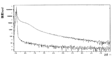
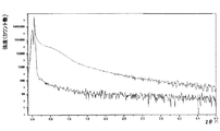
図3〜図6は、図1,2による装置を用いて行われた測定例を既存の従来装置で行われた測定と比較して表している。 3 to 6 show an example of measurement performed using the apparatus according to FIGS. 1 and 2 in comparison with the measurement performed with an existing conventional apparatus.
図3は、最初に従来のブラッグ・ブレンターノ法を用いた粉末のブラッグ・ブレンターノ測定の結果と、続いて平坦な傾斜多層構造を備える本発明の装置を用いて同一の粉末のブラッグ・ブレンターノ測定の結果を示している。 Figure 3 shows the results of Bragg Brentano measurement of powder using the conventional Bragg Brentano method first, followed by Bragg Brentano measurement of the same powder using the device of the present invention with a flat gradient multilayer structure. Results are shown.
図4は、SAXS測定に同一の装置を用いた結果を表している。この場合、上側の曲線は試料の測定から得られ、かつ、下側の曲線は空の試料容器での走査結果を示している。空の試料ホルダのバックグラウンドは低く、「特徴を示すことなく」低い2θ角度にまで低下している。このことは、SAXS解析に良く適していることを示している。 FIG. 4 shows the result of using the same apparatus for SAXS measurement. In this case, the upper curve is obtained from the measurement of the sample, and the lower curve shows the scanning result with an empty sample container. The background of the empty sample holder is low, dropping to a low 2θ angle “without characterization”. This indicates that it is well suited for SAXS analysis.
比較用に図5は、集束入射ビームミラーを用いた他の装置による同一試料での結果を示している。本発明の方法が、従来の装置を用いた結果と同じくらい良好な結果を与えていることがわかる。 For comparison, FIG. 5 shows the results for the same sample from another apparatus using a focused incident beam mirror. It can be seen that the method of the present invention gives results as good as those using conventional devices.
図6は反射率測定に同一の装置を用いた結果を表している。この場合、本発明の装置を用いた結果と従来装置を用いた結果とは事実上区別できない。 FIG. 6 shows the result of using the same apparatus for reflectance measurement. In this case, the result using the apparatus of the present invention and the result using the conventional apparatus are virtually indistinguishable.
よって本発明の配置は、ブラッグ・ブレンターノ測定、SAXS測定、及び反射率測定のいずれについても、当該装置を大きく変化させることなく良好な結果を与える。 Therefore, the arrangement of the present invention gives good results without greatly changing the apparatus for any of Bragg-Brentano measurement, SAXS measurement, and reflectance measurement.
コリメータは単一スリットである必要はない。 The collimator need not be a single slit.
これは、第2方向でのコリメーション−つまり追加の測定−たとえばGI-SAXS(微小角入射SAXS)、面内回折等−を可能にする第1方向でのコリメーションに対して垂直なコリメーション−を追加しても良い。 This adds collimation perpendicular to the first direction that allows collimation in the second direction-ie additional measurements-eg GI-SAXS (small angle incidence SAXS), in-plane diffraction, etc. You may do it.
具体的には、コリメータ内に大きな開口部が存在する場合には、装置の設定はブラッグ・ブレンターノ測定に適し、開口部が非常に狭いスリットである場合には、装置の設定はSAXSと反射率測定に適する。狭いスリットに加えて、狭いスリットに対して垂直なスリットを備える2つの小さなマスクが設けられる場合、これは、狭いX線の照射線を生成するのではなく、微小回折に用いることのできる試料上での小さな照射領域を生成する。 Specifically, if there is a large opening in the collimator, the instrument setting is suitable for Bragg-Brentano measurements, and if the opening is a very narrow slit, the instrument setting is SAXS and reflectivity. Suitable for measurement. If two small masks with slits perpendicular to the narrow slit are provided in addition to the narrow slit, this does not produce a narrow X-ray radiation, but on a sample that can be used for microdiffraction. Generate a small illuminated area at.
さらなるコリメーションを加える他のより複雑な方法は、平坦な傾斜多層構造8とコリメータ16−この場合具体的には可変2Dコリメータであって良い−との間にさらなる平坦、放物形状、楕円形状、又は双曲形状の多層構造を供することである。
Other more complex ways of adding further collimation are further flat, parabolic, elliptical, between the flat tilted
これらのさらなる配置は、当該装置の単純さをある程度犠牲にしてさらなる自由度を加える。しかし基本は依然として、平坦な傾斜多層構造と1つ以上のコリメータとの組み合わせである。 These additional arrangements add additional freedom at the expense of some simplicity of the device. But the basics are still a combination of a flat gradient multilayer structure and one or more collimators.
場合によっては、コリメータ16は、ブラッグ・ブレンターノ測定時には完全に除去され、かつ、SAXS又は反射率測定時にのみ戻されて良い。
In some cases, the
任意の適切な検出器が用いられて良い。特に100μm×100μmよりも小さな点拡がり関数を有する2次元X線検出器が、相対的に小さな装置サイズを可能にするのに用いられて良い。 Any suitable detector may be used. In particular, a two-dimensional X-ray detector having a point spread function smaller than 100 μm × 100 μm may be used to allow a relatively small device size.
上述の説明は粉末試料に焦点を当てたが、本発明は広範な種類の試料で用いられるときにも良好な結果を与えることができる。 Although the above description has focused on powder samples, the present invention can give good results when used with a wide variety of samples.
2 X線源
4 試料台
6 試料
8 平坦な傾斜多層構造
10 ビーム
12 線状焦点
14 明確な焦点
16 コリメータ
20 X線検出器
2 X-ray source
4 Sample stage
6 samples
8 Flat inclined multilayer structure
10 beam
12 Linear focus
14 Clear focus
16 Collimator
20 X-ray detector
Claims (9)
試料台;
前記焦点から前記試料台へX線を案内するため、前記焦点と前記試料台との間に設けられた平坦な傾斜多層構造;及び
前記試料台上に載置された試料からのX線を検出するX線検出器;を有し、さらに
ブラッグ・ブレンターノ幾何学配置測定用の広い実効開口部及びSAXS測定用の狭い実効開口部に調節可能である可変の開口部を有する、前記平坦な傾斜多層構造と前記試料台との間に設けられたコリメータ;
を有し、
前記広い実効開口部のビーム発散角は少なくとも0.1°で、かつ、
前記狭い実効開口部のビーム発散角は0.07°を超えない、X線回折装置。 A focused X-ray source;
Sample stage;
A flat inclined multilayer structure provided between the focal point and the sample stage for guiding X-rays from the focal point to the sample stage; and detecting X-rays from the sample placed on the sample stage Said flat inclined multilayer having a variable effective opening adjustable to a wide effective opening for measuring Bragg-Brentano geometry and a narrow effective opening for measuring SAXS A collimator provided between the structure and the sample stage;
Have
The beam divergence angle of the wide effective aperture is at least 0.1 °, and
An X-ray diffractometer in which the beam divergence angle of the narrow effective aperture does not exceed 0.07 °.
試料台;
前記焦点から前記試料台へX線を案内するため、前記焦点と前記試料台との間に設けられた平坦な傾斜多層構造;
前記試料台上に載置された試料からのX線を検出するX線検出器;及び
ブラッグ・ブレンターノ幾何学配置測定用の広い実効開口部及びSAXS測定用の狭い実効開口部に調節可能である、前記平坦な傾斜多層構造と前記試料台との間に設けられたコリメータ;
を有するX線回折装置の操作方法であって:
前記コリメータを広い実効開口部に調節してブラッグ・ブレンターノ幾何学配置での測定を実行する段階;及び、
前記コリメータを狭い実効開口部に調節して小角X線散乱-SAXS-測定を実行する段階;
を有し、
前記広い実効開口部のビーム発散角は少なくとも0.1°で、かつ、
前記狭い実効開口部のビーム発散角は0.07°を超えない、方法。 A focused X-ray source;
Sample stage;
A flat inclined multilayer structure provided between the focal point and the sample stage for guiding X-rays from the focal point to the sample stage;
X-ray detector for detecting X-rays from a sample placed on the sample table; and adjustable to a wide effective opening for Bragg-Brentano geometry measurement and a narrow effective opening for SAXS measurement A collimator provided between the flat inclined multilayer structure and the sample stage;
A method of operating an X-ray diffractometer having:
Adjusting the collimator to a wide effective aperture to perform measurements in a Bragg-Brentano geometry; and
Adjusting the collimator to a narrow effective aperture to perform small angle X-ray scattering-SAXS-measurement;
Have
The beam divergence angle of the wide effective aperture is at least 0.1 °, and
The method wherein the beam divergence angle of the narrow effective aperture does not exceed 0.07 °.
Applications Claiming Priority (2)
| Application Number | Priority Date | Filing Date | Title |
|---|---|---|---|
| EP14151339.0A EP2896960B1 (en) | 2014-01-15 | 2014-01-15 | X-ray apparatus for SAXS and Bragg-Brentano measurements |
| EP14151339.0 | 2014-01-15 |
Publications (2)
| Publication Number | Publication Date |
|---|---|
| JP2015132608A JP2015132608A (en) | 2015-07-23 |
| JP6564572B2 true JP6564572B2 (en) | 2019-08-21 |
Family
ID=49955942
Family Applications (1)
| Application Number | Title | Priority Date | Filing Date |
|---|---|---|---|
| JP2015004708A Active JP6564572B2 (en) | 2014-01-15 | 2015-01-14 | X-ray equipment |
Country Status (4)
| Country | Link |
|---|---|
| US (1) | US9640292B2 (en) |
| EP (1) | EP2896960B1 (en) |
| JP (1) | JP6564572B2 (en) |
| CN (1) | CN104777179B (en) |
Families Citing this family (5)
| Publication number | Priority date | Publication date | Assignee | Title |
|---|---|---|---|---|
| US9851313B2 (en) * | 2015-03-03 | 2017-12-26 | Panalytical B.V. | Quantitative X-ray analysis—ratio correction |
| US10753890B2 (en) * | 2017-03-09 | 2020-08-25 | Malvern Panalytical B.V. | High resolution X-ray diffraction method and apparatus |
| EP3553507A1 (en) * | 2018-04-13 | 2019-10-16 | Malvern Panalytical B.V. | X-ray analysis apparatus |
| EP3553506A3 (en) | 2018-04-13 | 2020-02-12 | Malvern Panalytical B.V. | Apparatus and method for x-ray analysis with hybrid control of beam divergence |
| CN113030139B (en) * | 2021-05-31 | 2021-08-13 | 中国工程物理研究院激光聚变研究中心 | Novel crystal and compact imaging device |
Family Cites Families (21)
| Publication number | Priority date | Publication date | Assignee | Title |
|---|---|---|---|---|
| US3885153A (en) * | 1974-06-20 | 1975-05-20 | Us Energy | Multi-layer monochromator |
| JPS5462883A (en) * | 1977-10-28 | 1979-05-21 | Cho Lsi Gijutsu Kenkyu Kumiai | Xxray slit of variable form |
| JPH04215024A (en) * | 1990-12-11 | 1992-08-05 | Toshiba Corp | Ceramic member inspecting method |
| JP2940757B2 (en) * | 1992-04-09 | 1999-08-25 | 理学電機工業株式会社 | X-ray diffraction analyzer |
| GB2266040B (en) * | 1992-04-09 | 1996-03-13 | Rigaku Ind Corp | X-ray analysis apparatus |
| DE4407278A1 (en) * | 1994-03-04 | 1995-09-07 | Siemens Ag | X-ray analyzer |
| GB2296125B (en) * | 1994-12-16 | 1998-04-29 | Moli Energy | Pre-graphitic carbonaceous insertion compounds and use as anodes in rechargeable batteries |
| JP3734366B2 (en) * | 1998-03-20 | 2006-01-11 | 株式会社リガク | X-ray analyzer |
| JP3821414B2 (en) * | 1998-04-03 | 2006-09-13 | 株式会社リガク | X-ray diffraction analysis method and X-ray diffraction analysis apparatus |
| JPH11304728A (en) * | 1998-04-23 | 1999-11-05 | Hitachi Ltd | X-ray measuring device |
| DE19833524B4 (en) * | 1998-07-25 | 2004-09-23 | Bruker Axs Gmbh | X-ray analyzer with gradient multilayer mirror |
| KR20020060741A (en) * | 2000-09-22 | 2002-07-18 | 에모또 간지 | Quantitative measuring method and apparatus of metal phase using x-ray diffraction method, and method for making plated steel sheet using them |
| DE10107914A1 (en) * | 2001-02-14 | 2002-09-05 | Fraunhofer Ges Forschung | Arrangement for X-ray analysis applications |
| DE10162093A1 (en) * | 2001-12-18 | 2003-07-10 | Bruker Axs Gmbh | X-ray optical system with an aperture in the focus of an X-ray mirror |
| EP1732087A3 (en) * | 2002-06-19 | 2007-03-28 | Xenocs | Optical assemblage and associated device |
| JP3757199B2 (en) * | 2002-09-03 | 2006-03-22 | 株式会社リガク | X-ray small angle scattering optical system |
| JP3697246B2 (en) * | 2003-03-26 | 2005-09-21 | 株式会社リガク | X-ray diffractometer |
| JP4860418B2 (en) * | 2006-10-10 | 2012-01-25 | 株式会社リガク | X-ray optical system |
| JP4861283B2 (en) * | 2007-09-28 | 2012-01-25 | 株式会社リガク | X-ray diffraction apparatus and X-ray diffraction method |
| KR100949141B1 (en) * | 2007-11-06 | 2010-03-25 | 원광대학교산학협력단 | Characteristics of Radiation Acquisition in X-Ray Tube Light Sources |
| US8548123B2 (en) * | 2010-04-29 | 2013-10-01 | Bruker Axs, Inc. | Method and apparatus for using an area X-ray detector as a point detector in an X-ray diffractometer |
-
2014
- 2014-01-15 EP EP14151339.0A patent/EP2896960B1/en active Active
- 2014-11-19 US US14/547,976 patent/US9640292B2/en active Active
- 2014-12-29 CN CN201410833194.3A patent/CN104777179B/en active Active
-
2015
- 2015-01-14 JP JP2015004708A patent/JP6564572B2/en active Active
Also Published As
| Publication number | Publication date |
|---|---|
| CN104777179B (en) | 2019-01-08 |
| JP2015132608A (en) | 2015-07-23 |
| CN104777179A (en) | 2015-07-15 |
| EP2896960A1 (en) | 2015-07-22 |
| US9640292B2 (en) | 2017-05-02 |
| US20150200030A1 (en) | 2015-07-16 |
| EP2896960B1 (en) | 2017-07-26 |
Similar Documents
| Publication | Publication Date | Title |
|---|---|---|
| JP6564572B2 (en) | X-ray equipment | |
| US9383324B2 (en) | Laboratory X-ray micro-tomography system with crystallographic grain orientation mapping capabilities | |
| US8094780B2 (en) | Two dimensional small angle X-Ray scattering camera | |
| US9222901B2 (en) | X-ray diffraction method of mapping grain structures in a crystalline material sample, and an X-ray diffraction apparatus | |
| JP2008014861A (en) | Ultra-small angle X-ray scattering measurement device | |
| CN110389143B (en) | X-ray analysis apparatus | |
| JP6392850B2 (en) | Beam generating unit and X-ray small angle scattering apparatus | |
| US9031203B2 (en) | X-ray beam system offering 1D and 2D beams | |
| JP6009156B2 (en) | Diffractometer | |
| JP4868660B2 (en) | X-ray analysis apparatus provided with multilayer mirror and emission collimator | |
| Buchanan et al. | Effective modeling of high-energy laboratory-based x-ray phase contrast imaging utilizing absorption masks or gratings | |
| Kern | The platform concept–fitting the instrument to the need | |
| Kern | Basic design principles and instrument geometry considerations |
Legal Events
| Date | Code | Title | Description |
|---|---|---|---|
| A621 | Written request for application examination |
Free format text: JAPANESE INTERMEDIATE CODE: A621 Effective date: 20170908 |
|
| A977 | Report on retrieval |
Free format text: JAPANESE INTERMEDIATE CODE: A971007 Effective date: 20180604 |
|
| A131 | Notification of reasons for refusal |
Free format text: JAPANESE INTERMEDIATE CODE: A131 Effective date: 20180612 |
|
| A521 | Request for written amendment filed |
Free format text: JAPANESE INTERMEDIATE CODE: A523 Effective date: 20180912 |
|
| A02 | Decision of refusal |
Free format text: JAPANESE INTERMEDIATE CODE: A02 Effective date: 20190122 |
|
| A521 | Request for written amendment filed |
Free format text: JAPANESE INTERMEDIATE CODE: A523 Effective date: 20190520 |
|
| A911 | Transfer to examiner for re-examination before appeal (zenchi) |
Free format text: JAPANESE INTERMEDIATE CODE: A911 Effective date: 20190527 |
|
| TRDD | Decision of grant or rejection written | ||
| A01 | Written decision to grant a patent or to grant a registration (utility model) |
Free format text: JAPANESE INTERMEDIATE CODE: A01 Effective date: 20190702 |
|
| A61 | First payment of annual fees (during grant procedure) |
Free format text: JAPANESE INTERMEDIATE CODE: A61 Effective date: 20190729 |
|
| R150 | Certificate of patent or registration of utility model |
Ref document number: 6564572 Country of ref document: JP Free format text: JAPANESE INTERMEDIATE CODE: R150 |
|
| R250 | Receipt of annual fees |
Free format text: JAPANESE INTERMEDIATE CODE: R250 |
|
| R250 | Receipt of annual fees |
Free format text: JAPANESE INTERMEDIATE CODE: R250 |
|
| R250 | Receipt of annual fees |
Free format text: JAPANESE INTERMEDIATE CODE: R250 |