JP6563997B2 - Terminal device and ophthalmic system - Google Patents

Terminal device and ophthalmic system Download PDF

Info

Publication number
JP6563997B2
JP6563997B2 JP2017186503A JP2017186503A JP6563997B2 JP 6563997 B2 JP6563997 B2 JP 6563997B2 JP 2017186503 A JP2017186503 A JP 2017186503A JP 2017186503 A JP2017186503 A JP 2017186503A JP 6563997 B2 JP6563997 B2 JP 6563997B2
Authority
JP
Japan
Prior art keywords
information
main body
unit
mobile terminal
terminal
Prior art date
Legal status (The legal status is an assumption and is not a legal conclusion. Google has not performed a legal analysis and makes no representation as to the accuracy of the status listed.)
Ceased
Application number
JP2017186503A
Other languages
Japanese (ja)
Other versions
JP2018027317A (en
Inventor
亮一 名達
亮一 名達
Current Assignee (The listed assignees may be inaccurate. Google has not performed a legal analysis and makes no representation or warranty as to the accuracy of the list.)
Topcon Corp
Original Assignee
Topcon Corp
Priority date (The priority date is an assumption and is not a legal conclusion. Google has not performed a legal analysis and makes no representation as to the accuracy of the date listed.)
Filing date
Publication date
Family has litigation
First worldwide family litigation filed litigation Critical https://patents.darts-ip.com/?family=61247991&utm_source=google_patent&utm_medium=platform_link&utm_campaign=public_patent_search&patent=JP6563997(B2) "Global patent litigation dataset” by Darts-ip is licensed under a Creative Commons Attribution 4.0 International License.
Application filed by Topcon Corp filed Critical Topcon Corp
Priority to JP2017186503A priority Critical patent/JP6563997B2/en
Publication of JP2018027317A publication Critical patent/JP2018027317A/en
Application granted granted Critical
Publication of JP6563997B2 publication Critical patent/JP6563997B2/en
Ceased legal-status Critical Current
Anticipated expiration legal-status Critical

Links

Images

Description

この発明は端末装置及び眼科システムに関する。   The present invention relates to a terminal device and an ophthalmic system.

眼科分野では様々な眼科装置が用いられる。眼科装置は、被検眼に関する情報を取得するための装置である。眼科装置には、被検眼の検査に用いられる眼科検査装置、被検眼の観察や撮影に用いられる眼科観察装置、被検眼の治療に用いられる眼科治療装置などがある。眼科検査装置としては、自覚式検眼装置(視標呈示装置等)、他覚式検眼装置(レフラクトメータ、ケラトメータ等)、視野計、眼圧計、スペキュラーマイクロスコープ、ウェーブフロントアナライザーなどがある。眼科観察装置としては、細隙灯顕微鏡、眼底カメラ、光干渉断層計(OCT)、走査型レーザ検眼鏡(SLO)、手術用顕微鏡、超音波診断装置などがある。眼科治療装置としては、レーザ光凝固装置、レーザ角膜屈折矯正装置などがある。   Various ophthalmic devices are used in the ophthalmic field. The ophthalmologic apparatus is an apparatus for acquiring information related to the eye to be examined. Examples of the ophthalmologic apparatus include an ophthalmologic examination apparatus used for examining an eye to be examined, an ophthalmologic observation apparatus used for observing and photographing the eye to be examined, and an ophthalmic treatment apparatus used for treating the eye to be examined. Examples of the ophthalmologic examination apparatus include a subjective optometry apparatus (target presentation apparatus, etc.), an objective optometry apparatus (refractometer, keratometer, etc.), a perimeter, a tonometer, a specular microscope, a wavefront analyzer, and the like. Examples of the ophthalmologic observation apparatus include a slit lamp microscope, a fundus camera, an optical coherence tomography (OCT), a scanning laser ophthalmoscope (SLO), a surgical microscope, and an ultrasonic diagnostic apparatus. Examples of the ophthalmologic treatment apparatus include a laser photocoagulation apparatus and a laser corneal refraction correction apparatus.

これら眼科装置の操作は、装置自体に設けられたユーザインターフェイス(操作デバイス、表示デバイス)を用いて行われている。また、被検者情報や検者情報の入力や、検査条件・撮影条件の設定は、装置自体に設けられたユーザインターフェイスや、装置近傍に固定的に設置されたコンピュータ、或いはバーコードリーダ等を用いることにより実行されている。更に、検査や撮影により取得されたデータの保存は、コンパクトフラッシュ(登録商標)カードやUSBメモリ等の記録媒体を装置に取り付けることにより、或いは、装置近傍のコンピュータやネットワーク上のサーバに通信線を介して送信することにより実行されている。   These ophthalmologic apparatuses are operated using a user interface (operation device, display device) provided in the apparatus itself. In addition, input of patient information, examiner information, and setting of examination conditions and imaging conditions can be performed by using a user interface provided in the apparatus itself, a computer fixedly installed in the vicinity of the apparatus, or a barcode reader. It is executed by using. Furthermore, the data acquired by inspection and photographing can be stored by attaching a recording medium such as a CompactFlash (registered trademark) card or USB memory to the device, or by connecting a communication line to a computer in the vicinity of the device or a server on the network. It is executed by sending through.

特開2006−26000号公報JP 2006-26000 A 特開2001−178676号公報JP 2001-178676 A

このように、従来の眼科装置においては、通信可能に構成されたコンピュータを近傍に設けたり、バーコードリーダを接続したりする必要があった。なお、眼科分野では上記のような多種多様の装置が日常的に用いられるが、コンピュータやバーコードリーダを眼科装置ごとに設けている現状のシステム構成は、コストやスペース、操作性などにおいて好適とは言い難い。   As described above, in the conventional ophthalmic apparatus, it is necessary to provide a computer configured to be communicable in the vicinity or to connect a barcode reader. In the ophthalmology field, a wide variety of devices as described above are used on a daily basis. However, the current system configuration in which a computer and a barcode reader are provided for each ophthalmic device is suitable in terms of cost, space, operability, and the like. Is hard to say.

この発明の目的は、眼科装置の近傍にコンピュータを固定的に設置したり、バーコードリーダを接続したりする必要を無くすことにある。   An object of the present invention is to eliminate the need to install a computer in the vicinity of an ophthalmic apparatus or connect a barcode reader.

実施形態は、複数の眼科装置を操作するための携帯端末であって、表示部と、前記複数の眼科装置のうちの第1の装置を操作するための第1のGUIと第2の装置を操作するための第2のGUIとを表示部に表示させる手段と、前記第1のGUIから入力された信号に基づいて操作情報を生成し、かつ、前記第2のGUIから入力された信号に基づいて操作情報を生成する手段と、前記第1のGUIから入力された信号に基づく前記操作情報を前記第1の装置に送信し、かつ、前記第2のGUIから入力された信号に基づく前記操作情報を前記第2の装置に送信する手段と、前記複数の眼科装置のうちから情報の送信先を選択するためのGUIを前記表示部に表示させる手段とを含む。 The embodiment is a portable terminal for operating a plurality of ophthalmologic apparatuses, and includes a display unit, a first GUI and a second apparatus for operating a first apparatus among the plurality of ophthalmologic apparatuses. Means for displaying a second GUI for operation on the display unit, operation information is generated based on the signal input from the first GUI, and the signal input from the second GUI Means for generating operation information based on the signal, the operation information based on the signal input from the first GUI, transmitted to the first device, and the signal based on the signal input from the second GUI Means for transmitting operation information to the second device, and means for displaying on the display unit a GUI for selecting a transmission destination of information from the plurality of ophthalmic devices .

この発明によれば、眼科装置の近傍にコンピュータを固定的に設置したり、バーコードリーダを接続したりする必要がない。   According to the present invention, there is no need to install a computer in the vicinity of the ophthalmic apparatus or connect a barcode reader.

実施形態に係る眼科装置の構成の例を示す概略外観図である。It is a schematic external view which shows the example of a structure of the ophthalmologic apparatus which concerns on embodiment. 実施形態に係る眼科装置の構成の例を示す概略外観図である。It is a schematic external view which shows the example of a structure of the ophthalmologic apparatus which concerns on embodiment. 実施形態に係る眼科装置の構成の例を示す概略ブロック図である。It is a schematic block diagram which shows the example of a structure of the ophthalmologic apparatus which concerns on embodiment. 実施形態に係る眼科装置の構成の例を示す概略ブロック図である。It is a schematic block diagram which shows the example of a structure of the ophthalmologic apparatus which concerns on embodiment. 実施形態に係る眼科装置の構成の例を示す概略図である。It is the schematic which shows the example of a structure of the ophthalmologic apparatus which concerns on embodiment. 実施形態に係る眼科装置の動作の例を示すフローチャートである。It is a flowchart which shows the example of operation | movement of the ophthalmologic apparatus which concerns on embodiment. 実施形態に係る眼科装置の動作の例を示すフローチャートである。It is a flowchart which shows the example of operation | movement of the ophthalmologic apparatus which concerns on embodiment. 実施形態に係る眼科装置の動作の例を示すフローチャートである。It is a flowchart which shows the example of operation | movement of the ophthalmologic apparatus which concerns on embodiment. 実施形態に係る眼科装置の動作の例を示すフローチャートである。It is a flowchart which shows the example of operation | movement of the ophthalmologic apparatus which concerns on embodiment. 実施形態に係る眼科装置の構成の例を示す概略ブロック図である。It is a schematic block diagram which shows the example of a structure of the ophthalmologic apparatus which concerns on embodiment. 実施形態に係る眼科装置の動作の例を示すフローチャートである。It is a flowchart which shows the example of operation | movement of the ophthalmologic apparatus which concerns on embodiment. 実施形態に係る眼科装置の構成の例を示す概略ブロック図である。It is a schematic block diagram which shows the example of a structure of the ophthalmologic apparatus which concerns on embodiment. 実施形態に係る眼科装置の動作の例を示すフローチャートである。It is a flowchart which shows the example of operation | movement of the ophthalmologic apparatus which concerns on embodiment. 実施形態に係る眼科装置の構成の例を示す概略ブロック図である。It is a schematic block diagram which shows the example of a structure of the ophthalmologic apparatus which concerns on embodiment. 実施形態に係る眼科装置の動作の例を示すフローチャートである。It is a flowchart which shows the example of operation | movement of the ophthalmologic apparatus which concerns on embodiment. 実施形態に係る眼科装置の構成の例を示す概略ブロック図である。It is a schematic block diagram which shows the example of a structure of the ophthalmologic apparatus which concerns on embodiment. 実施形態に係る眼科装置の動作の例を示すフローチャートである。It is a flowchart which shows the example of operation | movement of the ophthalmologic apparatus which concerns on embodiment. 実施形態に係る眼科装置の構成の例を示す概略ブロック図である。It is a schematic block diagram which shows the example of a structure of the ophthalmologic apparatus which concerns on embodiment.

この発明に係る眼科装置の実施形態の一例について、図面を参照しながら詳細に説明する。なお、この明細書に記載された文献の記載内容を実施形態に援用することが可能である。以下、実施形態に係る眼科装置の全体構成について簡単に説明した後に、様々な実施形態について説明する。   An example of an embodiment of an ophthalmologic apparatus according to the present invention will be described in detail with reference to the drawings. In addition, it is possible to use description content of the literature described in this specification for embodiment. Hereinafter, after briefly explaining the overall configuration of the ophthalmic apparatus according to the embodiment, various embodiments will be described.

[全体構成]
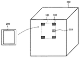
実施形態に係る眼科装置の外観構成の一例を図1Aおよび図1Bに示す。実施形態に係る眼科装置は、少なくとも本体部100を含む。また、実施形態に係る眼科装置は、携帯端末200も含んでいてもよい。
[overall structure]
An example of the external configuration of the ophthalmologic apparatus according to the embodiment is shown in FIGS. 1A and 1B. The ophthalmologic apparatus according to the embodiment includes at least a main body 100. The ophthalmologic apparatus according to the embodiment may also include the mobile terminal 200.

眼科装置は、たとえば、被検眼の検査に用いられる眼科検査装置、被検眼の観察や撮影に用いられる眼科観察装置、被検眼の治療に用いられる眼科治療装置のいずれかである。なお、これら眼科装置の具体例については前述した。また、眼科装置は、異種の眼科検査装置(眼科観察装置、眼科治療装置)を組み合わせた複合機であってもよいし、眼科検査装置、眼科観察装置および眼科治療装置のうちの2つ以上を組み合わせた複合機であってもよい。   The ophthalmologic apparatus is, for example, any one of an ophthalmic examination apparatus used for examining an eye to be examined, an ophthalmologic observation apparatus used for observing or photographing an eye to be examined, and an ophthalmic treatment apparatus used for treating an eye to be examined. Specific examples of these ophthalmologic apparatuses have been described above. In addition, the ophthalmic apparatus may be a combined machine in which different types of ophthalmic examination apparatuses (ophthalmic observation apparatus, ophthalmic treatment apparatus) are combined, or two or more of the ophthalmic examination apparatus, the ophthalmic observation apparatus, and the ophthalmic treatment apparatus are included. A combined multifunction machine may be used.

本体部100は、被検眼の情報を取得するための構成を有する。たとえば、本体部100には、光学系、駆動機構、制御回路などが設けられている。これらの構成は、従来の同種の眼科装置と同様である。   The main body 100 has a configuration for acquiring information about the eye to be examined. For example, the main body 100 is provided with an optical system, a drive mechanism, a control circuit, and the like. These configurations are the same as those of conventional ophthalmic devices of the same type.

携帯端末200は、携帯可能なコンピュータ端末である。これは、従来の眼科装置の近傍に設置されたコンピュータ端末(据え置き型コンピュータ端末)と異なる。携帯端末200の例として、スマートフォン、タブレット端末、個人情報端末(PDA)、携帯電話、ノート型パーソナルコンピュータなどがある。   The portable terminal 200 is a portable computer terminal. This is different from a computer terminal (stationary computer terminal) installed in the vicinity of a conventional ophthalmic apparatus. Examples of the mobile terminal 200 include a smartphone, a tablet terminal, a personal information terminal (PDA), a mobile phone, and a notebook personal computer.

ユーザは、眼科装置が設置された施設(医療機関、眼鏡店等)内において、更には施設外において、携帯端末200を携行することができる。また、施設内に設置されている眼科装置の台数は任意である。それら眼科装置のうち携帯端末200と連係して動作する眼科装置それぞれが、実施形態に係る眼科装置として用いられる。   The user can carry the mobile terminal 200 in a facility (a medical institution, a spectacle store, etc.) where the ophthalmologic apparatus is installed, and further outside the facility. Further, the number of ophthalmic devices installed in the facility is arbitrary. Each of the ophthalmologic apparatuses that operate in conjunction with the mobile terminal 200 is used as the ophthalmologic apparatus according to the embodiment.

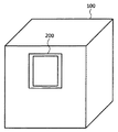
本体部100の筺体には、図1Aに示す装着部101が設けられている。装着部101は、本体部100に携帯端末200を装着するための構成を有する。ここで、本体部100に対する携帯端末200の取り付け操作および取り外し操作を容易に行なえるように、装着部101が構成されていることが好ましい。なお、本体部100に携帯端末200を装着している際、携帯端末200の背面が装着部101に接触する。なお、携帯端末200の背面とは、携帯端末200の(主たる)表示部が設けられた面(正面)の対向面である。携帯端末200が本体部100に装着された状態を図1Bに示す。   A mounting portion 101 shown in FIG. 1A is provided on the housing of the main body 100. The mounting unit 101 has a configuration for mounting the mobile terminal 200 to the main body unit 100. Here, it is preferable that the mounting unit 101 is configured so that the mounting operation and the detaching operation of the mobile terminal 200 with respect to the main body unit 100 can be easily performed. Note that when the mobile terminal 200 is attached to the main body 100, the back surface of the mobile terminal 200 contacts the attachment part 101. Note that the back surface of the mobile terminal 200 is an opposite surface of the surface (front surface) of the mobile terminal 200 on which the (main) display unit is provided. A state in which the mobile terminal 200 is mounted on the main body 100 is shown in FIG. 1B.

装着部101の構成例を説明する。装着部101は、図1Aに示すように磁石102を有する。磁石102は、たとえば、携帯端末200に応じた形状およびサイズを有する矩形状の装着部101の四隅にそれぞれ設けられる。携帯端末200は、磁石102の引力により装着部101に装着される。なお、本体部100から携帯端末200を取り外す操作の容易化を考慮して、磁石102が発生する磁力の強さを決定することができる。また、磁力に反応しない材質の携帯端末200が用いられる場合、磁力に反応する材質からなる部材(磁石シート、金属シート等)を携帯端末200の背面に取り付けることができる。この部材は、少なくとも、磁石102に対応する位置に設けられる。また、携帯端末200の携帯性を考慮し、この部材は軽量であることが好ましい。   A configuration example of the mounting unit 101 will be described. The mounting portion 101 has a magnet 102 as shown in FIG. 1A. For example, the magnets 102 are provided at the four corners of the rectangular mounting portion 101 having a shape and size corresponding to the mobile terminal 200, respectively. The portable terminal 200 is attached to the attachment unit 101 by the attractive force of the magnet 102. Note that the strength of the magnetic force generated by the magnet 102 can be determined in consideration of facilitating the operation of removing the mobile terminal 200 from the main body 100. When the mobile terminal 200 made of a material that does not react to magnetic force is used, a member (magnet sheet, metal sheet, etc.) made of a material that reacts to magnetic force can be attached to the back surface of the mobile terminal 200. This member is provided at least at a position corresponding to the magnet 102. Further, considering the portability of the portable terminal 200, this member is preferably lightweight.

装着部101の他の構成例を説明する。携帯端末200の筺体と係合する係合部を装着部101に設ける。係合部の例を説明する。携帯端末200の背面にフック状の部材が設けられている場合、係合部は、このフック状部材が挿入される部材(たとえば環状の部材)を含む。逆に、係合部がフック状部材である場合には、携帯端末200の背面に環状部材等を設けることができる。   Another configuration example of the mounting unit 101 will be described. An engaging portion that engages with the housing of the mobile terminal 200 is provided in the mounting portion 101. An example of the engaging portion will be described. When a hook-shaped member is provided on the back surface of the mobile terminal 200, the engaging portion includes a member (for example, an annular member) into which the hook-shaped member is inserted. Conversely, when the engaging portion is a hook-shaped member, an annular member or the like can be provided on the back surface of the mobile terminal 200.

また、携帯端末200全体が挿入される袋状、箱状または枠状の部材を係合部とすることも可能である。この係合部は、少なくとも携帯端末200の表示部に対応する部分が透明になっている。また、表示部をタッチパネルとして用いる場合には、この透明な部分は柔軟な膜状の部材として形成される。なお、表示部に対応する部分が開口になっていてもよい。また、本例の係合部は、携帯端末200の全体を覆うものである必要はなく、携帯端末200が本体部100から容易に脱落しない程度の範囲(たとえば携帯端末200の半分程度の部分)を覆うように構成されていてもよい。   Further, a bag-like, box-like or frame-like member into which the entire mobile terminal 200 is inserted can be used as the engaging portion. The engaging portion is transparent at least at a portion corresponding to the display portion of the mobile terminal 200. Moreover, when using a display part as a touch panel, this transparent part is formed as a flexible film-like member. Note that a portion corresponding to the display unit may be an opening. In addition, the engaging portion of this example does not need to cover the entire mobile terminal 200, and the range in which the mobile terminal 200 is not easily detached from the main body portion 100 (for example, about half of the mobile terminal 200). It may be configured to cover.

装着部101またはその近傍には、通信インターフェイス103が設けられている。通信インターフェイス103は、装着部101に装着された状態の携帯端末200との間における情報通信を担う。なお、携帯端末200は、前述の例示からも明らかなように、情報通信機能を有する。携帯端末200および通信インターフェイス103は、同じ通信規格に準拠している。この通信規格は、Bluetooth(登録商標)等の非接触通信(無線通信)でもよいし、USB等の接触通信(有線通信)でもよい。なお、着脱の利便性を考慮すると非接触通信が好ましいと考えられる。一方、多数の画像データを高速で伝送する必要がある場合などには、接触通信を使用する利点もあると考えられる。   A communication interface 103 is provided at or near the mounting portion 101. The communication interface 103 is responsible for information communication with the portable terminal 200 that is attached to the attachment unit 101. Note that the mobile terminal 200 has an information communication function, as is apparent from the above-described examples. The portable terminal 200 and the communication interface 103 conform to the same communication standard. This communication standard may be non-contact communication (wireless communication) such as Bluetooth (registered trademark) or contact communication (wired communication) such as USB. Note that non-contact communication is preferable in consideration of convenience of attachment / detachment. On the other hand, when it is necessary to transmit a large number of image data at high speed, it is considered that there is an advantage of using contact communication.

この眼科装置に関する情報を携帯端末200に表示させるための構成は任意である。たとえば、本体部100にウェブサーバとしての機能を設け、携帯端末200にウェブブラウザとしての機能を設けることができる。つまり、ウェブページを生成する機能を本体部100に設け、このウェブページを閲覧する機能を携帯端末200に設けることができる。この場合、本体部100にはウェブページを生成するウェブサーバ機能を奏するアプリケーションソフトウェアが搭載され、携帯端末200にはウェブページを表示するウェブブラウザ機能を奏するアプリケーションソフトウェアが搭載される。   A configuration for displaying information on the ophthalmologic apparatus on the portable terminal 200 is arbitrary. For example, the main body 100 can be provided with a function as a web server, and the mobile terminal 200 can be provided with a function as a web browser. That is, a function for generating a web page can be provided in the main body unit 100 and a function for browsing the web page can be provided in the mobile terminal 200. In this case, application software having a web server function for generating a web page is installed in the main body 100, and application software having a web browser function for displaying a web page is installed in the mobile terminal 200.

〈第1の実施形態〉
この実施形態では、本体部100と携帯端末200との間における情報通信の例を説明する。
<First Embodiment>
In this embodiment, an example of information communication between the main body 100 and the mobile terminal 200 will be described.

本体部100と携帯端末200との間で伝送される情報の例として、操作情報、被検者情報、動作条件情報、検者情報がある。   Examples of information transmitted between the main body 100 and the portable terminal 200 include operation information, subject information, operation condition information, and examiner information.

操作情報は、携帯端末200を用いて本体部100を操作するために携帯端末200から本体部100に送信される情報である。   The operation information is information transmitted from the mobile terminal 200 to the main body 100 in order to operate the main body 100 using the mobile terminal 200.

被検者情報は、被検者に関する情報であり、被検者の識別情報(患者ID、顧客ID等)、被検者の電子カルテに記載されている情報(氏名、年齢、性別、検査結果、撮影画像等)などを含む。   The subject information is information relating to the subject, such as identification information (patient ID, customer ID, etc.) of the subject, information (name, age, sex, test result) described in the electronic medical record of the subject. , Photographed images, etc.).

動作条件情報は、本体部100の動作条件を示す情報であり、本体部100で検査や撮影を行なうときの本体部100の各部の設定情報(検査条件、撮影条件等)を含む。また、本体部100の複数の部位の動作条件が関連付けられている場合、つまり1つ以上の動作モードが予め設定されている場合、動作条件情報は、動作モードの識別情報を含んでいてもよい。   The operating condition information is information indicating the operating conditions of the main body 100, and includes setting information (inspection conditions, imaging conditions, etc.) of each part of the main body 100 when the main body 100 performs inspection and imaging. Further, when the operation conditions of a plurality of parts of the main body 100 are associated, that is, when one or more operation modes are set in advance, the operation condition information may include identification information of the operation mode. .

動作条件情報の具体例を説明する。眼科装置が光干渉断層計である場合、動作条件情報には、計測対象部位(黄斑、視神経乳頭等)を示す固視位置情報、対象物に対するスキャン態様を示すスキャン条件などが含まれる。眼科装置が眼底カメラである場合、動作条件情報には、固視位置情報、撮影モード情報(FAG蛍光撮影、ICG蛍光撮影、自発蛍光撮影等)、照明光の光量を示す情報などが含まれる。   A specific example of the operating condition information will be described. When the ophthalmologic apparatus is an optical coherence tomography, the operation condition information includes fixation position information indicating a measurement target part (macular, optic nerve head, etc.), a scan condition indicating a scan mode for the object, and the like. When the ophthalmologic apparatus is a fundus camera, the operation condition information includes fixation position information, imaging mode information (FAG fluorescence imaging, ICG fluorescence imaging, spontaneous fluorescence imaging, etc.), information indicating the amount of illumination light, and the like.

検者情報は、眼科装置の操作者に関する情報であり、操作者の識別情報(医師ID、店員ID等)、氏名などを含む。   The examiner information is information regarding the operator of the ophthalmologic apparatus, and includes operator identification information (doctor ID, clerk ID, etc.), name, and the like.

この実施形態ではこれら全ての情報を伝送可能な構成について説明するが、これらのうちの任意の1つ以上の情報を伝送可能な構成を適用することが可能である。   In this embodiment, a configuration capable of transmitting all of these pieces of information will be described. However, a configuration capable of transmitting any one or more of these pieces of information can be applied.

[構成]
この実施形態に係る眼科装置の構成を説明する。眼科装置の構成例を図2に示す。
[Constitution]
The configuration of the ophthalmologic apparatus according to this embodiment will be described. A configuration example of the ophthalmologic apparatus is shown in FIG.

(本体部100)
本体部100は、本体制御部110と、本体通信部120と、着脱検知部130と、被検眼情報取得部140と、本体操作部150と、本体記憶部160とを有する。
(Main body 100)
The main body unit 100 includes a main body control unit 110, a main body communication unit 120, an attachment / detachment detection unit 130, an eye information acquisition unit 140, a main body operation unit 150, and a main body storage unit 160.

(本体制御部110)
本体制御部110は、本体部100の各部を制御する。本体制御部110は、マイクロプロセッサ、RAM、ROM、ハードディスクドライブ、フラッシュメモリ等を含んで構成される。ROM、ハードディスクドライブ、フラッシュメモリなどには、制御用のコンピュータプログラムやデータが予め記憶されている。このコンピュータプログラム等に基づいてマイクロプロセッサが動作することにより、本体制御部110による制御が実行される。
(Main body control unit 110)
The main body control unit 110 controls each unit of the main body unit 100. The main body control unit 110 includes a microprocessor, RAM, ROM, hard disk drive, flash memory, and the like. A computer program and data for control are stored in advance in the ROM, hard disk drive, flash memory, and the like. Control by the main body control unit 110 is executed by the microprocessor operating based on the computer program or the like.

(本体通信部120)
本体通信部120は、携帯端末200(端末通信部220)との間で情報通信を行う。本体通信部120は、図1Aに示す通信インターフェイス103を含んで構成される。本体通信部120は、携帯端末200と同じ規格の通信デバイスを含む。
(Main unit communication unit 120)
The main body communication unit 120 performs information communication with the mobile terminal 200 (terminal communication unit 220). The main body communication unit 120 includes the communication interface 103 shown in FIG. 1A. The main body communication unit 120 includes a communication device having the same standard as the portable terminal 200.

(着脱検知部130)
着脱検知部130は、本体部100(装着部101)に対する携帯端末200の着脱状態を検知する。特に、着脱検知部130は、本体部100に携帯端末200が取り付けられたこと、および、本体部100から携帯端末200が取り外されたことを、それぞれ検知する。
(Removal detection unit 130)
The attachment / detachment detection unit 130 detects the attachment / detachment state of the mobile terminal 200 with respect to the main body unit 100 (the attachment unit 101). In particular, the attachment / detachment detection unit 130 detects that the mobile terminal 200 has been attached to the main body 100 and that the mobile terminal 200 has been removed from the main body 100.

携帯端末200の着脱状態を検知可能であれば、着脱検知部130の構成は任意である。たとえば、装着部101に装着されている携帯端末200の背面が接触する位置に設けられたマイクロスイッチを、着脱検知部130として用いることができる。それにより、このマイクロスイッチは、携帯端末200の背面によって押下されているときに本体制御部110に信号(装着検知信号)を送る。本体制御部110は、マイクロスイッチから装着検知信号が入力されている状態を、携帯端末200が装着されている状態(装着状態)として認識する。一方、本体制御部110は、装着検知信号が入力されていない状態を、携帯端末200が取り外されている状態(非装着状態)と認識する。また、本体制御部110は、非装着状態から装着状態への移行が検知されたタイミング、つまり装着検知信号の入力が開始されたタイミングを、本体部100に携帯端末200が取り付けられたタイミングとして認識する。逆に、本体制御部110は、非装着状態から装着状態への移行が検知されたタイミング、つまり装着検知信号の入力が停止したタイミングを、本体部100から携帯端末200が取り外されたタイミングとして認識する。   The configuration of the attachment / detachment detection unit 130 is arbitrary as long as the attachment / detachment state of the portable terminal 200 can be detected. For example, a micro switch provided at a position where the back surface of the mobile terminal 200 attached to the attachment unit 101 contacts can be used as the attachment / detachment detection unit 130. Thereby, this micro switch sends a signal (mounting detection signal) to the main body control unit 110 when being pressed by the back surface of the mobile terminal 200. The main body control unit 110 recognizes the state where the mounting detection signal is input from the microswitch as the state where the mobile terminal 200 is mounted (mounted state). On the other hand, the main body control unit 110 recognizes a state in which no attachment detection signal is input as a state in which the mobile terminal 200 is removed (non-attached state). In addition, the main body control unit 110 recognizes the timing when the transition from the non-wearing state to the wearing state is detected, that is, the timing when the input of the wearing detection signal is started as the timing when the mobile terminal 200 is attached to the main body portion 100. To do. Conversely, the main body control unit 110 recognizes the timing at which the transition from the non-wearing state to the wearing state is detected, that is, the timing at which the input of the wearing detection signal is stopped, as the timing at which the portable terminal 200 is removed from the main body portion 100. To do.

着脱検知部130の他の構成例を説明する。携帯端末200には、(非接触型)ICカードが設けられているものとする。更に、着脱検知部130は、このICカードと同じ様式のカードリーダを含むものとする。このカードリーダは、装着部101に装着された状態の携帯端末200のICカードの近接位置に設けられる。装着部101に携帯端末200が装着されると、カードリーダは、携帯端末200のICカードに記録された情報を読み取る。この記録情報は、たとえば、本体部100とともに使用可能な携帯端末であることを示す情報や、携帯端末200の識別情報などである。ICカードの記録情報を読み取ったカードリーダは、読み取った情報、または読み取った旨を示す情報を、本体制御部110に送信する。本体制御部110は、カードリーダからの入力情報により、携帯端末200が装着されたことを認識する。ここで、カードリーダは、ICカードの記録情報を所定時間ごとに読み取るものとする。本体部100から携帯端末200が取り外されると、カードリーダは、ICカードの記録情報を読み取ることができなくなる。本体制御部110は、カードリーダからの信号に基づき、携帯端末200が取り外されたことを認識することができる。   Another configuration example of the attachment / detachment detection unit 130 will be described. It is assumed that the portable terminal 200 is provided with a (non-contact type) IC card. Further, the attachment / detachment detection unit 130 includes a card reader of the same style as the IC card. This card reader is provided in the proximity position of the IC card of the portable terminal 200 mounted on the mounting unit 101. When the portable terminal 200 is attached to the attachment unit 101, the card reader reads information recorded on the IC card of the portable terminal 200. The recorded information is, for example, information indicating that the mobile terminal can be used with the main body 100, identification information of the mobile terminal 200, and the like. The card reader that has read the recorded information of the IC card transmits the read information or information indicating that the information has been read to the main body control unit 110. The main body control unit 110 recognizes that the portable terminal 200 is attached based on input information from the card reader. Here, it is assumed that the card reader reads the recorded information of the IC card every predetermined time. When the mobile terminal 200 is removed from the main body 100, the card reader cannot read the recorded information on the IC card. The main body control unit 110 can recognize that the portable terminal 200 has been removed based on a signal from the card reader.

以上、着脱検知部130の構成例を2つ説明したが、これらに限定されるものではない。たとえば、電気、磁気、光(赤外線等)を利用した構成の着脱検知部130を適用することが可能である。   Although two configuration examples of the attachment / detachment detection unit 130 have been described above, the present invention is not limited to these. For example, it is possible to apply the attachment / detachment detection unit 130 having a configuration using electricity, magnetism, or light (infrared rays or the like).

(被検眼情報取得部140)
被検眼情報取得部140は、被検眼の情報を取得する。被検眼情報取得部140は、取得される情報に応じた構成を有する。眼科装置が眼科検査装置を含む場合、被検眼情報取得部140は、被検眼の検査を行なってその結果を取得する。眼科装置が眼科観察装置を含む場合、被検眼情報取得部140は、被検眼の撮影を行なって画像を取得する。眼科装置が眼科治療装置を含む場合、被検眼情報取得部140は、治療時に撮影された画像や、治療効果を示す情報を取得する。
(Eye eye information acquisition unit 140)
The eye information acquisition unit 140 acquires information about the eye to be examined. The eye information acquisition unit 140 has a configuration corresponding to the acquired information. When the ophthalmologic apparatus includes an ophthalmic examination apparatus, the eye information acquisition unit 140 inspects the eye to be inspected and acquires the result. When the ophthalmologic apparatus includes an ophthalmologic observation apparatus, the subject eye information acquisition unit 140 captures the subject eye and acquires an image. When the ophthalmologic apparatus includes an ophthalmologic treatment apparatus, the eye information acquisition unit 140 acquires an image taken at the time of treatment and information indicating a treatment effect.

(本体操作部150)
本体操作部150は、本体部100に設けられた操作デバイスである。本体操作部150は、ボタン、ノブ、ダイヤル等のハードウェアを含んでいてもよいし、表示デバイスに表示されるGUIを含んでいてもよい。GUIは、図示しない表示デバイスに本体制御部110によって表示される。
(Main unit operation unit 150)
The main body operation unit 150 is an operation device provided in the main body unit 100. The main body operation unit 150 may include hardware such as buttons, knobs, and dials, and may include a GUI displayed on a display device. The GUI is displayed by the main body control unit 110 on a display device (not shown).

ユーザによる操作を受けた本体操作部150は、その操作内容に応じた信号を本体制御部110に送信する。本体制御部110は、この信号に基づいて制御を行う。なお、ユーザが本体操作部150を操作することで発生した駆動力によって部材を動作させる機構を設けてもよい。すなわち、本体制御部110を介した電動制御ではなく、力学的な機構によって本体部100の操作を行えるようにしてもよい。   Upon receiving an operation by the user, the main body operation unit 150 transmits a signal corresponding to the operation content to the main body control unit 110. The main body control unit 110 performs control based on this signal. Note that a mechanism for operating the member by a driving force generated by the user operating the main body operation unit 150 may be provided. That is, the main body 100 may be operated by a mechanical mechanism instead of the electric control via the main body control unit 110.

後述のように、この実施形態では、携帯端末200を用いて本体部100を操作することができる。本体操作部150により行われる操作は、携帯端末200による操作と重複していてもよいし、重複していなくてもよい。   As will be described later, in this embodiment, the main body 100 can be operated using the mobile terminal 200. The operation performed by the main body operation unit 150 may or may not overlap with the operation performed by the mobile terminal 200.

(本体記憶部160)
本体記憶部160は、各種の情報を記憶する。本体記憶部160に情報を書き込む処理、および本体記憶部160から情報を読み出す処理は、本体制御部110によって行われる。本体記憶部160は、たとえば、ハードディスクドライブやフラッシュメモリを含んで構成される。
(Main unit storage unit 160)
The main body storage unit 160 stores various types of information. The process of writing information into the main body storage unit 160 and the process of reading information from the main body storage unit 160 are performed by the main body control unit 110. The main body storage unit 160 includes, for example, a hard disk drive and a flash memory.

(携帯端末200)
携帯端末200は、端末制御部210と、端末通信部220と、表示部230と、端末操作部240と、端末記憶部250と、外部通信部260とを有する。
(Mobile terminal 200)
The portable terminal 200 includes a terminal control unit 210, a terminal communication unit 220, a display unit 230, a terminal operation unit 240, a terminal storage unit 250, and an external communication unit 260.

(端末制御部210)
端末制御部210は、携帯端末200の各部を制御する。端末制御部210は、マイクロプロセッサ、RAM、ROM、ハードディスクドライブ、フラッシュメモリ等を含んで構成される。ROM、ハードディスクドライブ、フラッシュメモリなどには、制御用のコンピュータプログラムやデータが予め記憶されている。このコンピュータプログラム等に基づいてマイクロプロセッサが動作することにより、端末制御部210による制御が実行される。
(Terminal control unit 210)
The terminal control unit 210 controls each unit of the mobile terminal 200. The terminal control unit 210 includes a microprocessor, RAM, ROM, hard disk drive, flash memory, and the like. A computer program and data for control are stored in advance in the ROM, hard disk drive, flash memory, and the like. Control by the terminal control unit 210 is executed by the microprocessor operating based on the computer program or the like.

(端末通信部220)
端末通信部220は、本体部100(本体通信部120)との間で情報通信を行う。端末通信部220は、本体通信部120と同じ規格の通信デバイスを含む。
(Terminal communication unit 220)
The terminal communication unit 220 performs information communication with the main body unit 100 (main body communication unit 120). The terminal communication unit 220 includes a communication device having the same standard as the main body communication unit 120.

(表示部230)
表示部230は、端末制御部210の制御を受けて各種の情報を表示する。表示部230としては、液晶ディスプレイ、有機ELディスプレイ等のフレットパネルディスプレイが用いられる。
(Display unit 230)
The display unit 230 displays various information under the control of the terminal control unit 210. As the display unit 230, a fret panel display such as a liquid crystal display or an organic EL display is used.

(端末操作部240)
端末操作部240は、ハードウェアからなる操作デバイスと、GUIの少なくとも一方を含む。前者は、携帯端末200の筺体に設けられたボタン、ノブ、ダイヤル等である。後者は、端末制御部210により表示部230に表示される。ユーザによる操作を受けた端末操作部240は、その操作内容に応じた信号を端末制御部210に送信する。端末制御部210は、この信号に基づいて制御を行う。
(Terminal operation unit 240)
The terminal operation unit 240 includes at least one of an operation device made of hardware and a GUI. The former is a button, knob, dial, or the like provided on the housing of the mobile terminal 200. The latter is displayed on the display unit 230 by the terminal control unit 210. Upon receiving an operation by the user, the terminal operation unit 240 transmits a signal corresponding to the operation content to the terminal control unit 210. The terminal control unit 210 performs control based on this signal.

(端末記憶部250)
端末記憶部250は、各種の情報を記憶する。端末記憶部250に情報を書き込む処理、および端末記憶部250から情報を読み出す処理は、端末制御部210によって行われる。端末記憶部250は、たとえば、ハードディスクドライブやフラッシュメモリを含んで構成される。
(Terminal storage unit 250)
The terminal storage unit 250 stores various types of information. The process of writing information to the terminal storage unit 250 and the process of reading information from the terminal storage unit 250 are performed by the terminal control unit 210. The terminal storage unit 250 includes, for example, a hard disk drive and a flash memory.

(外部通信部260)
外部通信部260は、外部装置(当該眼科装置と異なる装置)300との間で情報通信を行う。この情報通信は、有線通信でも無線通信でもよい。
(External communication unit 260)
The external communication unit 260 performs information communication with an external apparatus (an apparatus different from the ophthalmologic apparatus) 300. This information communication may be wired communication or wireless communication.

外部装置300の例としてサーバがある。サーバは、たとえば当該施設内に構築されたLAN上に設けられている。サーバの例として、医療機関に設置されたファイルサーバ(電子カルテサーバ、画像サーバ(DICOMサーバ)等)や、眼鏡店に設置されたファイルサーバ(顧客管理サーバ等)がある。また、外部装置300は、医師が使用するコンピュータ端末(医師端末)等であってもよい。   An example of the external device 300 is a server. The server is provided on a LAN constructed in the facility, for example. Examples of the server include a file server (electronic medical record server, image server (DICOM server), etc.) installed in a medical institution, and a file server (customer management server, etc.) installed in an eyeglass store. The external device 300 may be a computer terminal (doctor terminal) used by a doctor.

外部装置300は、当該施設外に設置されていてもよい。その場合、携帯端末200と外部装置300は、インターネットや広域専用線を介して情報通信を行う。   The external device 300 may be installed outside the facility. In that case, the portable terminal 200 and the external device 300 perform information communication via the Internet or a wide area dedicated line.

外部通信部260は、たとえばLANカードや、インターネット用通信インターフェイスなど、通信先となる外部装置300に応じた構成を有する。   The external communication unit 260 has a configuration according to the external device 300 that is a communication destination, such as a LAN card or an Internet communication interface.

(端末記憶部250に記憶されている情報)
端末記憶部250には、各種の情報が予め記憶されている。「予め」とは、本体部100との間で情報通信を行う前を示す。端末記憶部250に記憶されている情報の例を図3に示す。図3に示す端末記憶部250には、被検者情報251と、動作条件情報252と、検者情報253とが予め記憶されている。これら情報については前述した。
(Information stored in terminal storage unit 250)
Various kinds of information are stored in the terminal storage unit 250 in advance. “Preliminary” indicates before information communication with the main body 100 is performed. An example of information stored in the terminal storage unit 250 is shown in FIG. In the terminal storage unit 250 shown in FIG. 3, subject information 251, operating condition information 252, and examiner information 253 are stored in advance. These information are described above.

これら情報は、たとえば、端末制御部210が外部通信部260を制御して外部装置300から読み出して端末記憶部250に記憶させたものである。また、これら情報は、端末操作部240を用いて入力または加工された情報であってもよい。   For example, the terminal control unit 210 controls the external communication unit 260 to read out the information from the external device 300 and store the information in the terminal storage unit 250. These pieces of information may be information input or processed using the terminal operation unit 240.

この実施形態では、被検者情報251と動作条件情報252とが予め対応付けられている。この対応付けは、一の被検者の被検眼について、どのような情報をどのように取得するかを示すものである。より具体的には、この対応付けは、たとえば、被検者IDと動作条件情報とを関連付けることによりなされる。   In this embodiment, the subject information 251 and the operating condition information 252 are associated in advance. This association indicates what information is acquired and how for the eye of one subject. More specifically, this association is made, for example, by associating the subject ID with the operating condition information.

被検者情報251には、複数の被検者に関する情報が含まれていてもよい。たとえば、これから検査等を行う患者のリストを被検者情報251として用いることができる。その場合、上記対応付けは被検者ごとになされている。つまり、被検者情報251と動作条件情報252は、複数の被検者に対して適用される本体部100の動作条件のリストとして構成される。その具体例を図4に示す。図4に示す情報には、被検者情報251に相当する患者IDと、動作条件情報252に相当する条件A、B、CおよびDとが記録されている。患者ID「0001」には、条件A「a1」、条件B「b5」、条件C「c2」および条件D「d3」が対応付けられている。その他の患者IDについても同様に、条件A〜Dが対応付けられている。   The subject information 251 may include information regarding a plurality of subjects. For example, a list of patients to be examined from now on can be used as the subject information 251. In this case, the association is made for each subject. In other words, the subject information 251 and the operating condition information 252 are configured as a list of operating conditions of the main body 100 applied to a plurality of subjects. A specific example is shown in FIG. In the information shown in FIG. 4, a patient ID corresponding to the subject information 251 and conditions A, B, C, and D corresponding to the operation condition information 252 are recorded. The condition A “a1”, the condition B “b5”, the condition C “c2”, and the condition D “d3” are associated with the patient ID “0001”. Similarly, conditions A to D are associated with other patient IDs.

[動作]
実施形態に係る眼科装置の動作例を説明する。
[Operation]
An operation example of the ophthalmologic apparatus according to the embodiment will be described.

(動作例1)
図5を参照しつつ、本体部100に携帯端末200を装着したときに実行される処理の例を説明する。携帯端末200の端末記憶部250には、被検者情報251、動作条件情報252および検者情報253が事前に記憶されているものとする。
(Operation example 1)
An example of processing executed when the mobile terminal 200 is attached to the main body 100 will be described with reference to FIG. It is assumed that subject information 251, operating condition information 252, and examiner information 253 are stored in advance in the terminal storage unit 250 of the portable terminal 200.

(S1:携帯端末を装着する)
ユーザが、本体部100に携帯端末200を装着する。
(S1: Wear a mobile device)
A user attaches the mobile terminal 200 to the main body 100.

(S2:本体部が装着を検知する)
本体部100の着脱検知部130および本体制御部110が、本体部100に携帯端末200が装着されたことを検知する。携帯端末200の装着が検知されたことを受けて、本体制御部110は、携帯端末200からの情報を受信する準備をする。たとえば、本体制御部110は、本体通信部120を制御して受信待機状態にする。
(S2: The main unit detects wearing)
The attachment / detachment detection unit 130 and the main body control unit 110 of the main body 100 detect that the mobile terminal 200 is attached to the main body 100. In response to detecting that the mobile terminal 200 is mounted, the main body control unit 110 prepares to receive information from the mobile terminal 200. For example, the main body control unit 110 controls the main body communication unit 120 to enter a reception standby state.

(S3:携帯端末が送信情報を準備する)
ユーザにより所定の操作が行われたことを受けて、携帯端末200の端末制御部210は、本体部100に向けて送信される情報を準備する。この処理は、たとえば、端末記憶部250に記憶されている情報のうちから送信される情報(送信情報)を端末制御部210が選択的に読み出す処理を含む。
(S3: The mobile terminal prepares transmission information)
In response to a predetermined operation performed by the user, the terminal control unit 210 of the mobile terminal 200 prepares information to be transmitted toward the main body unit 100. This process includes, for example, a process in which terminal control unit 210 selectively reads information (transmission information) transmitted from information stored in terminal storage unit 250.

送信情報は、たとえば、本体部100による検査等に最初に供される被検者の被検者情報251を含む。この被検者情報251の選択は、たとえば、ユーザが端末操作部240を用いて手動で行なわれる。また、図4に示すようなリストの最初に記録されている被検者情報251(患者ID等)を端末制御部210が選択するようにしてもよい。この場合、検査等が行われる順序と、複数の被検者情報とが予め対応付けられている。この対応付けは、たとえば、検査等が行われる順序で複数の被検者情報をリストに記録することにより実現される。また、検査等の順序を示す順序情報を複数の被検者情報に対応付けておくようにしてもよい。   The transmission information includes, for example, the subject information 251 of the subject that is first used for an examination or the like by the main body unit 100. The selection of the subject information 251 is manually performed by the user using the terminal operation unit 240, for example. Further, the terminal control unit 210 may select the subject information 251 (patient ID or the like) recorded at the beginning of the list as shown in FIG. In this case, the order in which examinations are performed and a plurality of pieces of subject information are associated in advance. This association is realized, for example, by recording a plurality of subject information in a list in the order in which examinations and the like are performed. In addition, order information indicating the order of examination or the like may be associated with a plurality of pieces of subject information.

また、送信情報は、動作条件情報252および/または検者情報253を含んでいてもよい。被検者情報251と動作条件情報252の双方が送信情報に含まれる場合、たとえば図4に示すように、互いに対応付けられた被検者情報251と動作条件情報252が送信情報として選択される。また、たとえば眼鏡店で用いられる他覚式検眼装置や健康診断に用いられる眼科装置のように、全ての被検者に対して同じ動作条件が適用される場合などには、送信情報に被検者情報251が含まれなくてもよい。この動作例では、被検者情報251、動作条件情報252および検者情報253が送信情報に含まれるものとする。   The transmission information may include operating condition information 252 and / or examiner information 253. When both the subject information 251 and the operation condition information 252 are included in the transmission information, for example, as shown in FIG. 4, the subject information 251 and the operation condition information 252 associated with each other are selected as the transmission information. . In addition, when the same operating conditions are applied to all subjects, such as an objective optometry device used in a spectacle store or an ophthalmologic device used in a medical examination, Person information 251 may not be included. In this operation example, it is assumed that the subject information 251, the operation condition information 252, and the examiner information 253 are included in the transmission information.

(S4:携帯端末が送信情報を表示する)
端末制御部210は、ステップ3で準備された送信情報を表示部230に表示させる。ここで、読み出された全ての情報を表示させてもよいし、その一部のみを表示させてもよい。後者の例として、ユーザが自身の識別情報(医師ID等)を確認する必要性がないと判断する場合、検者情報253を表示させなくてよい。
(S4: mobile terminal displays transmission information)
The terminal control unit 210 causes the display unit 230 to display the transmission information prepared in step 3. Here, all the read information may be displayed, or only a part thereof may be displayed. As an example of the latter, when it is determined that the user does not need to confirm his / her identification information (doctor ID or the like), the examiner information 253 may not be displayed.

(S5:携帯端末が送信情報を送信する)
端末制御部210は、端末通信部220を制御して、ステップ3で準備された送信情報を送信させる。
(S5: The mobile terminal transmits transmission information)
The terminal control unit 210 controls the terminal communication unit 220 to transmit the transmission information prepared in step 3.

(S6:本体部が送信情報を受信する)
ステップ5で送信された送信情報は、本体部100の本体通信部120により受信される。
(S6: The main unit receives the transmission information)
The transmission information transmitted in step 5 is received by the main body communication unit 120 of the main body unit 100.

送信情報が受信されない場合に再送信を行なうように構成できる。その一例として、本体制御部110が携帯端末200の装着の検知(ステップ2)に対応して計時を開始し、所定時間が経過しても送信情報が受信されなかった場合に警告を出力するようにしてもよい。他の例として、送信情報が受信されたときにその旨を示す情報を本体部100から携帯端末200に返信するように構成し、ステップ5の送信の後に携帯端末200が当該返信を受けなかった場合に警告を出力するように構成してもよい。なお、ここでの警告は、たとえば、本体部100または携帯端末200による視覚情報や聴覚情報である。この警告に応じてユーザが再送信の指示を携帯端末200に入力する。また、上記返信がなかった場合に、端末制御部210が自動で再送信を行わせるようにしてもよい。   Retransmission can be performed when transmission information is not received. As an example, the main body control unit 110 starts timing in response to detection of attachment of the mobile terminal 200 (step 2), and outputs a warning when transmission information is not received even after a predetermined time has elapsed. It may be. As another example, when transmission information is received, information indicating that is sent from the main unit 100 to the portable terminal 200, and the portable terminal 200 did not receive the reply after the transmission in step 5 In some cases, a warning may be output. The warning here is, for example, visual information or auditory information from the main body 100 or the mobile terminal 200. In response to this warning, the user inputs a re-transmission instruction to the portable terminal 200. Moreover, when there is no said reply, you may make it the terminal control part 210 perform automatic retransmission.

(S7:本体部が送信情報を記憶する)
本体制御部110は、ステップ6で受信された送信情報を本体記憶部160に記憶させる。この後に行われる本体部100による検査等において、本体制御部110は、記憶された動作条件情報に基づいて本体部100の各部を制御する。以上で、この動作例は終了となる。
(S7: The main unit stores transmission information)
The main body control unit 110 stores the transmission information received in step 6 in the main body storage unit 160. In the inspection or the like performed by the main body 100 thereafter, the main body control unit 110 controls each part of the main body 100 based on the stored operating condition information. Thus, this operation example ends.

(動作例2)
図6を参照しつつ、被検者の変更に伴い実行される処理の例を説明する。携帯端末200の端末記憶部250には、被検者情報251、動作条件情報252および検者情報253が事前に記憶されているものとする。また、動作例1のステップ3で説明したように、先の被検者の被検者情報やそれに対応する動作条件情報は、既に本体部100に送信されているものとする。
(Operation example 2)
With reference to FIG. 6, an example of processing executed in accordance with the change of the subject will be described. It is assumed that subject information 251, operating condition information 252, and examiner information 253 are stored in advance in the terminal storage unit 250 of the portable terminal 200. Further, as described in step 3 of the operation example 1, it is assumed that the subject information of the previous subject and the operation condition information corresponding thereto have already been transmitted to the main body unit 100.

(S11:被検者の変更)
被検者の変更に伴い、ユーザは所定の操作を行なう。この操作は、たとえば携帯端末200の端末操作部240を用いて行われる。端末操作部240は、この操作に応じた信号を本体制御部110に送る。この信号は、被検者の変更を示す被検者変更情報に相当する。
(S11: Change of subject)
The user performs a predetermined operation in accordance with the change of the subject. This operation is performed using the terminal operation part 240 of the portable terminal 200, for example. The terminal operation unit 240 sends a signal corresponding to this operation to the main body control unit 110. This signal corresponds to the subject change information indicating the change of the subject.

また、検査等の内容が予め決められている場合、目的の情報が本体部100により取得されたことをもって、被検者の変更を自動検出するように構成することができる。本体部100は、当該被検者に関する目的の情報が取得された旨を示す信号を携帯端末200に送信する。この信号は端末通信部220を介して端末制御部210に入力される。この信号は被検者変更情報に相当する。   Further, when the contents of the examination or the like are determined in advance, the change of the subject can be automatically detected when the target information is acquired by the main body unit 100. The main body 100 transmits a signal indicating that the target information regarding the subject has been acquired to the mobile terminal 200. This signal is input to the terminal control unit 210 via the terminal communication unit 220. This signal corresponds to the subject change information.

(S12:携帯端末が新たな被検者の送信情報を準備する)
被検者変更情報の入力を受けて、端末制御部210は、新たな被検者に関する送信情報を準備する。この送信情報は、新たな被検者の被検者情報を少なくとも含む。また、図4に示すリスト情報が用いられる場合などには、新たな被検者に対応する動作条件情報も送信情報に含まれる。
(S12: The mobile terminal prepares transmission information for a new subject)
In response to the input of the subject change information, the terminal control unit 210 prepares transmission information related to a new subject. This transmission information includes at least subject information of a new subject. Further, when the list information shown in FIG. 4 is used, operation condition information corresponding to a new subject is also included in the transmission information.

また、ここで実行される処理には、端末記憶部250に記憶されている情報のうちから新たな被検者の送信情報を端末制御部210が選択的に読み出す処理を含む。この処理は、たとえば動作例1のステップ3と同様にして実行される。   The processing executed here includes processing in which the terminal control unit 210 selectively reads out transmission information of a new subject from information stored in the terminal storage unit 250. This process is executed, for example, in the same manner as Step 3 of Operation Example 1.

(S13:携帯端末が新たな被検者の送信情報を表示する)
端末制御部210は、ステップ12で準備された送信情報を表示部230に表示させる。この処理は、たとえば動作例1のステップ4と同様にして実行される。
(S13: The mobile terminal displays the transmission information of the new subject)
The terminal control unit 210 causes the display unit 230 to display the transmission information prepared in step 12. This process is executed, for example, in the same manner as in Step 4 of Operation Example 1.

(S14:携帯端末が新たな被検者の送信情報を送信する)
端末制御部210は、端末通信部220を制御して、ステップ12で準備された送信情報を送信させる。
(S14: The mobile terminal transmits the transmission information of the new subject)
The terminal control unit 210 controls the terminal communication unit 220 to transmit the transmission information prepared in step 12.

(S15:本体部が新たな被検者の送信情報を受信する)
ステップ14で送信された送信情報は、本体部100の本体通信部120により受信される。ここで、動作例1で説明した再送信処理を行なってもよい。
(S15: The main body receives the transmission information of the new subject)
The transmission information transmitted in step 14 is received by the main body communication unit 120 of the main body unit 100. Here, the retransmission process described in the operation example 1 may be performed.

(S16:本体部が新たな被検者の送信情報を記憶する)
本体制御部110は、ステップ15で受信された送信情報を本体記憶部160に記憶させる。この後に行われる本体部100による検査等において、本体制御部110は、記憶された動作条件情報に基づいて本体部100の各部を制御する。以上で、この動作例は終了となる。
(S16: The main body stores the transmission information of the new subject)
The main body control unit 110 stores the transmission information received in step 15 in the main body storage unit 160. In the inspection or the like performed by the main body 100 thereafter, the main body control unit 110 controls each part of the main body 100 based on the stored operating condition information. Thus, this operation example ends.

(動作例3)
図7を参照しつつ、携帯端末200で本体部100を操作するための処理の例を説明する。
(Operation example 3)
With reference to FIG. 7, an example of processing for operating the main body unit 100 with the mobile terminal 200 will be described.

(S21:携帯端末がGUIを表示する)
携帯端末200の端末制御部210が、本体部100を操作するためのGUIを表示部230に表示させる。この処理は、たとえば、事前に携帯端末200にインストールされた所定のアプリケーションソフトウェアを起動することにより実行される。このGUIには、本体部100に各種の動作を実行させるためのソフトウェアキーが設けられている。また、携帯端末200に設けられたハードウェアキーについても本体部100の操作に使用できるように構成してもよい。また、このGUIには、本体部100の各種設定を行なうための機能などが設けられている。たとえば、動作条件情報にしたがって設定された動作条件を変更するための機能が設けられている。
(S21: The mobile terminal displays the GUI)
The terminal control unit 210 of the portable terminal 200 causes the display unit 230 to display a GUI for operating the main body unit 100. This process is executed by, for example, starting predetermined application software installed in the mobile terminal 200 in advance. The GUI is provided with software keys for causing the main body unit 100 to execute various operations. In addition, hardware keys provided on the mobile terminal 200 may be configured to be used for the operation of the main body 100. In addition, the GUI is provided with functions for performing various settings of the main body 100. For example, a function for changing the operating condition set according to the operating condition information is provided.

(S22:ユーザがGUIを操作する)
ユーザは、GUI等を用いて所望の操作を行なう。端末制御部210には、その操作内容を示す信号が入力される。
(S22: The user operates the GUI)
The user performs a desired operation using a GUI or the like. The terminal controller 210 receives a signal indicating the operation content.

(S23:携帯端末が操作情報を生成する)
端末制御部210は、GUI等から入力された信号に基づいて、本体部100に送信するための情報(操作情報)を生成する。
(S23: The mobile terminal generates operation information)
The terminal control unit 210 generates information (operation information) to be transmitted to the main body unit 100 based on a signal input from a GUI or the like.

(S24:携帯端末が操作情報を送信する)
端末制御部210は、端末通信部220を制御して、ステップ23で生成された操作情報を送信させる。
(S24: The mobile terminal transmits operation information)
The terminal control unit 210 controls the terminal communication unit 220 to transmit the operation information generated in step 23.

(S25:本体部が操作情報を受信する)
ステップ24で送信された操作情報は、本体部100の本体通信部120により受信される。
(S25: The main unit receives the operation information)
The operation information transmitted in step 24 is received by the main body communication unit 120 of the main body unit 100.

(S26:本体部が操作情報に対応する動作を実行する)
本体制御部110は、ステップ25で受信された操作情報に対応する動作を本体部100に実行させる。以上で、この動作例は終了となる。
(S26: The main body performs an operation corresponding to the operation information)
The main body control unit 110 causes the main body unit 100 to perform an operation corresponding to the operation information received in step 25. Thus, this operation example ends.

(動作例4)
図8を参照しつつ、本体部100により被検眼の情報が取得された後に実行される処理の例を説明する。なお、被検眼の複数の情報を取得する場合、以下の処理を実行するタイミングは、全ての情報を取得した後でも、一部の情報を取得した後でもよい。
(Operation example 4)
With reference to FIG. 8, an example of processing executed after the information on the eye to be examined is acquired by the main body unit 100 will be described. When acquiring a plurality of pieces of information on the eye to be examined, the timing for executing the following processing may be after all the information has been acquired or after some information has been acquired.

(S31:本体部が被検眼の情報を取得する)
本体部100の被検眼情報取得部140は、検査や撮影を行なうことにより、被検眼の情報(検査結果、画像等)を取得する。
(S31: The main body acquires information on the eye to be examined)
The eye information acquisition unit 140 of the main body unit 100 acquires information (test results, images, etc.) of the eye to be inspected by performing inspection and imaging.

(S32:本体部が被検眼の情報を送信する)
本体制御部110は、本体通信部120を制御して、ステップ31で取得された被検眼の情報を送信する。
(S32: The main body transmits information about the eye to be examined)
The main body control unit 110 controls the main body communication unit 120 to transmit the information on the eye to be examined acquired in step 31.

(S33:携帯端末が被検眼の情報を受信する)
ステップ32で送信された被検眼の情報は、携帯端末200の端末通信部220により受信される。
(S33: The mobile terminal receives information on the eye to be examined)
The information about the eye to be examined transmitted at step 32 is received by the terminal communication unit 220 of the portable terminal 200.

(S34:携帯端末が被検眼の情報を表示する)
端末制御部210は、ステップ33で受信された被検眼の情報を表示部230に表示させる。ここで、被検眼の情報を表示するためのアプリケーションソフトウェアが事前に起動され、端末制御部210は、このアプリケーションソフトウェアにしたがって、当該被検者の被検者情報251や、取得された被検眼の情報を表示する。
(S34: The mobile terminal displays information about the eye to be examined)
The terminal control unit 210 causes the display unit 230 to display the information on the eye to be examined received in step 33. Here, application software for displaying the information of the eye to be examined is activated in advance, and the terminal control unit 210 determines the subject information 251 of the subject and the acquired eye to be examined according to the application software. Display information.

(S35:携帯端末が外部装置に送信される情報を準備する)
被検眼の複数の情報を取得する場合であって、一部の情報を順次に携帯端末200に伝送する場合、全ての情報が伝送されるまでステップ31〜ステップ34が繰り返される。当該被検者に関する全ての情報を携帯端末200が受信すると、端末制御部210は、外部装置300に送信される情報を準備する。
(S35: The mobile terminal prepares information to be transmitted to the external device)
When a plurality of pieces of information on the eye to be examined are acquired, and when some pieces of information are sequentially transmitted to the mobile terminal 200, Steps 31 to 34 are repeated until all the information is transmitted. When the mobile terminal 200 receives all information related to the subject, the terminal control unit 210 prepares information to be transmitted to the external device 300.

この情報には、当該被検者の被検眼の情報の取得が終了したことを示す情報取得終了情報が少なくとも含まれる。また、この情報には、当該被検者の識別情報や、被検眼を示す情報(左眼/右眼情報)が含まれる。更に、この情報には、取得された被検眼の情報が含まれていてもよい。また、この情報には、ステップ31で情報が取得されたときの動作条件が含まれていてもよい。   This information includes at least information acquisition end information indicating that acquisition of information on the eye of the subject has been completed. Further, this information includes identification information of the subject and information (left eye / right eye information) indicating the eye to be examined. Furthermore, this information may include information on the acquired eye to be examined. Further, this information may include an operation condition when the information is acquired in step 31.

(S36:携帯端末が外部装置に情報を送信する)
端末制御部210は、外部通信部260を制御して、ステップ35で準備された情報を外部装置300に送信させる。なお、複数設けられた外部装置300に選択的に情報を送信する場合には、GUIを用いて送信先を選択できるように構成される。
(S36: The mobile terminal transmits information to the external device)
The terminal control unit 210 controls the external communication unit 260 to transmit the information prepared in step 35 to the external device 300. Note that, when information is selectively transmitted to a plurality of external devices 300 provided, a transmission destination can be selected using a GUI.

(S37:外部装置が情報を格納する)
外部装置300は、ステップ36で送信された情報を受信する。更に、外部装置300は、受信した情報を格納する。たとえば外部装置300が電子カルテサーバである場合、外部装置300は、受信した被検者の識別情報に基づいて当該被検者の電子カルテを検索し、この電子カルテに被検眼の情報等を記録する。外部装置300が画像サーバや顧客管理サーバ等である場合にも同様の処理が実行される。以上で、この動作例の処理は終了となる。
(S37: External device stores information)
The external device 300 receives the information transmitted in step 36. Furthermore, the external device 300 stores the received information. For example, when the external device 300 is an electronic medical record server, the external device 300 searches the subject's electronic medical record based on the received identification information of the subject, and records information on the eye to be examined in this electronic medical record. To do. A similar process is executed when the external device 300 is an image server, a customer management server, or the like. This is the end of the processing in this operation example.

[作用・効果]
実施形態に係る眼科装置の作用および効果を説明する。
[Action / Effect]
The operation and effect of the ophthalmologic apparatus according to the embodiment will be described.

実施形態に係る眼科装置は、少なくとも本体部100を含み、携帯端末200を含んでいても含んでいなくてもよい。携帯端末200は、通信機能を有している。本体部100は、被検眼の情報を取得するための機能を有する。本体部100は、装着部101と、本体通信部120(通信部)と、本体制御部110とを有する。装着部101には、携帯端末200が装着される。本体通信部120は、携帯端末200との間で情報通信を行なう。本体制御部110は、本体通信部120を介して携帯端末200から入力された情報に基づいて本体部100を制御する。   The ophthalmologic apparatus according to the embodiment includes at least the main body 100 and may or may not include the mobile terminal 200. The mobile terminal 200 has a communication function. The main body 100 has a function for acquiring information about the eye to be examined. The main body unit 100 includes a mounting unit 101, a main body communication unit 120 (communication unit), and a main body control unit 110. The portable terminal 200 is attached to the attachment unit 101. The main body communication unit 120 performs information communication with the mobile terminal 200. The main body control unit 110 controls the main body unit 100 based on information input from the portable terminal 200 via the main body communication unit 120.

本体通信部120が、装着部101に装着されている携帯端末200に対する操作内容を示す操作情報を受信し、かつ、本体制御部110が、受信された操作情報に基づいて、当該操作内容に対応する動作を本体部100に実行させるように構成できる。この構成によれば、携帯端末200を用いて本体部100を操作できるので、操作用のコンピュータを眼科装置の近傍に設置する必要がない。   The main body communication unit 120 receives operation information indicating the operation content for the mobile terminal 200 attached to the attachment unit 101, and the main body control unit 110 responds to the operation content based on the received operation information. The main body unit 100 can be configured to execute the operation to be performed. According to this configuration, since the main body unit 100 can be operated using the mobile terminal 200, it is not necessary to install a computer for operation in the vicinity of the ophthalmologic apparatus.

携帯端末200は、被検者情報251が予め記憶された端末記憶部250を有していてもよい。その場合、本体通信部120は、装着部101に装着されている携帯端末200の端末記憶部250に記憶されている被検者情報251を受信する。更に、本体部100は、受信された被検者情報251を記憶する本体記憶部160を有する。この構成によれば、携帯端末200を用いて被検者情報の入力を行なうことができるので、そのためのコンピュータを眼科装置の近傍に設置したり、バーコードリーダを設けたりする必要がない。   The portable terminal 200 may include a terminal storage unit 250 in which the subject information 251 is stored in advance. In that case, the main body communication unit 120 receives the subject information 251 stored in the terminal storage unit 250 of the mobile terminal 200 attached to the attachment unit 101. Furthermore, the main body unit 100 includes a main body storage unit 160 that stores the received subject information 251. According to this configuration, since it is possible to input subject information using the mobile terminal 200, it is not necessary to install a computer therefor in the vicinity of the ophthalmologic apparatus or provide a barcode reader.

携帯端末200は、複数の被検者のそれぞれの被検者情報251が予め記憶された端末記憶部250を有していてもよい。その場合、被検者の変更を示す被検者変更情報が入力されたときに、本体通信部120は、装着部101に装着されている携帯端末200の端末記憶部250に記憶されている新たな被検者の被検者情報251を受信する。更に、本体部100は、受信された新たな被検者の被検者情報を記憶する本体記憶部160を有する。この構成によれば、被検者の変更に伴う被検者情報の入力を、携帯端末200を用いて行なうことができるので、そのためのコンピュータを眼科装置の近傍に設置したり、バーコードリーダを設けたりする必要がない。また、新たな被検者の被検者情報が自動で入力されるので、被検者を変更するたびに被検者情報を入力する煩わしさがない。   The portable terminal 200 may have a terminal storage unit 250 in which the subject information 251 of each of a plurality of subjects is stored in advance. In that case, when the subject change information indicating the change of the subject is input, the main body communication unit 120 is newly stored in the terminal storage unit 250 of the mobile terminal 200 attached to the attachment unit 101. The subject information 251 of the subject is received. Furthermore, the main body unit 100 includes a main body storage unit 160 that stores the received subject information of the new subject. According to this configuration, since it is possible to input the subject information associated with the change of the subject using the mobile terminal 200, a computer for that purpose can be installed in the vicinity of the ophthalmologic apparatus or a barcode reader can be installed. There is no need to provide it. In addition, since the subject information of a new subject is automatically input, there is no trouble of inputting the subject information every time the subject is changed.

携帯端末200は、本体部100の動作条件を示す動作条件情報252が予め記憶された端末記憶部250を有していてもよい。その場合、本体通信部120は、装着部101に装着されている携帯端末200の端末記憶部250に記憶されている動作条件情報252を受信する。更に、本体制御部110は、受信された動作条件情報252に基づいて本体部100を制御する。この構成によれば、携帯端末200を用いて動作条件情報の入力を行なうことができるので、そのためのコンピュータを眼科装置の近傍に設置する必要がない。なお、前述したように、携帯端末200を用いて動作条件情報の変更操作を行なうことも可能である。   The mobile terminal 200 may include a terminal storage unit 250 in which operation condition information 252 indicating the operation conditions of the main body unit 100 is stored in advance. In that case, the main body communication unit 120 receives the operation condition information 252 stored in the terminal storage unit 250 of the mobile terminal 200 attached to the attachment unit 101. Further, the main body control unit 110 controls the main body unit 100 based on the received operating condition information 252. According to this configuration, since the operating condition information can be input using the portable terminal 200, it is not necessary to install a computer for this purpose in the vicinity of the ophthalmologic apparatus. As described above, the operation condition information can be changed using the portable terminal 200.

携帯端末200は、複数の被検者のそれぞれの被検者情報251と、本体部100の動作条件を示す動作条件情報252とが予め対応付けられて記憶された端末記憶部250を有していてもよい。その場合、被検者の変更を示す被検者変更情報が入力されたときに、本体通信部120は、装着部101に装着されている携帯端末200の端末記憶部250に記憶されている新たな被検者の被検者情報251と、この被検者情報251に対応付けられた動作条件情報252とを受信する。更に、本体部100は、受信された新たな被検者の被検者情報251および動作条件情報252を記憶する本体記憶部160を有する。そして、本体制御部110は、受信された動作条件情報252に基づいて本体部100を制御する。この構成によれば、被検者の変更に伴う被検者情報の入力を、携帯端末200を用いて行なうことができるので、そのためのコンピュータを眼科装置の近傍に設置したり、バーコードリーダを設けたりする必要がない。また、新たな被検者の被検者情報が自動で入力されるので、被検者を変更するたびに被検者情報を入力する煩わしさがない。また、携帯端末200を用いて動作条件情報の入力を行なうことができるので、そのためのコンピュータを眼科装置の近傍に配置させる必要がない。更に、被検者情報251と動作条件情報252が予め対応付けられているので、被検者ごとに動作条件が異なる場合における条件設定の手間を省くことができる。   The portable terminal 200 includes a terminal storage unit 250 in which the subject information 251 of each of a plurality of subjects and the operation condition information 252 indicating the operation conditions of the main body unit 100 are stored in association with each other. May be. In that case, when the subject change information indicating the change of the subject is input, the main body communication unit 120 is newly stored in the terminal storage unit 250 of the mobile terminal 200 attached to the attachment unit 101. The subject information 251 of the subject and the operating condition information 252 associated with the subject information 251 are received. Furthermore, the main body unit 100 includes a main body storage unit 160 that stores the received subject information 251 and operation condition information 252 of a new subject. Then, the main body control unit 110 controls the main body unit 100 based on the received operating condition information 252. According to this configuration, since it is possible to input the subject information associated with the change of the subject using the mobile terminal 200, a computer for that purpose can be installed in the vicinity of the ophthalmologic apparatus or a barcode reader can be installed. There is no need to provide it. In addition, since the subject information of a new subject is automatically input, there is no trouble of inputting the subject information every time the subject is changed. In addition, since the operating condition information can be input using the portable terminal 200, it is not necessary to arrange a computer therefor in the vicinity of the ophthalmologic apparatus. Furthermore, since the subject information 251 and the operation condition information 252 are associated in advance, it is possible to save time and effort for setting conditions when the operation conditions are different for each subject.

携帯端末200は、検者情報253が予め記憶された端末記憶部250を有していてもよい。その場合、本体通信部120は、装着部101に装着されている携帯端末200の端末記憶部250に記憶されている検者情報253を受信する。更に、本体部100は、受信された検者情報253を記憶する本体記憶部160を有する。この構成によれば、携帯端末200を用いて検者情報の入力を行なうことができるので、そのためのコンピュータを眼科装置の近傍に設置したり、バーコードリーダを設けたりする必要がない。   The portable terminal 200 may have a terminal storage unit 250 in which examiner information 253 is stored in advance. In that case, the main body communication unit 120 receives the examiner information 253 stored in the terminal storage unit 250 of the mobile terminal 200 attached to the attachment unit 101. Furthermore, the main body unit 100 includes a main body storage unit 160 that stores the received examiner information 253. According to this configuration, the examiner information can be input using the portable terminal 200, so that it is not necessary to install a computer for that purpose in the vicinity of the ophthalmologic apparatus or to provide a barcode reader.

携帯端末200は、携帯端末200から本体部100に送信された情報の少なくとも一部を表示する表示部230を有していてもよい。この構成によれば、本体部100への送信情報を携帯端末200にて確認することができる。また、送信情報を確認するためのコンピュータを眼科装置の近傍に設置する必要がない。   The mobile terminal 200 may include a display unit 230 that displays at least a part of information transmitted from the mobile terminal 200 to the main body unit 100. According to this configuration, transmission information to main body unit 100 can be confirmed on portable terminal 200. Further, it is not necessary to install a computer for confirming transmission information in the vicinity of the ophthalmologic apparatus.

本体通信部120が、本体部100により取得された被検眼の情報を送信し、かつ、携帯端末200が、受信された被検眼の情報を表示する表示部230を有していてもよい。この構成によれば、本体部100により取得された情報を携帯端末200で閲覧できるので、そのためのコンピュータを眼科装置の近傍に設置する必要がない。   The main body communication unit 120 may transmit information on the eye to be examined acquired by the main body unit 100, and the mobile terminal 200 may include a display unit 230 that displays the received information on the eye to be examined. According to this configuration, the information acquired by the main body unit 100 can be browsed by the portable terminal 200, so that it is not necessary to install a computer for this purpose in the vicinity of the ophthalmologic apparatus.

本体部100による当該被検者の被検眼の情報の取得が終了したときに、本体通信部120が、この被検眼の情報を送信するように構成できる。その場合、携帯端末200は、被検眼の情報を受信したときに、当該被検者の被検眼の情報の取得が終了したことを示す情報取得終了情報を外部装置300に送信する外部通信部260を有する。また、携帯端末200は、受信された当該被検眼の情報を情報取得終了情報とともに外部装置300に送信してもよい。この構成によれば、携帯端末200を用いて外部装置300への情報の送信を行なうことができるので、そのためのコンピュータを眼科装置の近傍に設置する必要がない。   The main body communication unit 120 can be configured to transmit the information about the eye to be examined when the main body unit 100 finishes acquiring the information about the subject's eye. In that case, when the mobile terminal 200 receives the information on the eye to be examined, the external communication unit 260 transmits information acquisition end information indicating that the acquisition of the information on the eye of the subject has been completed to the external device 300. Have Further, the mobile terminal 200 may transmit the received information about the eye to be examined to the external device 300 together with the information acquisition end information. According to this configuration, since information can be transmitted to the external device 300 using the mobile terminal 200, it is not necessary to install a computer therefor in the vicinity of the ophthalmologic apparatus.

〈第2の実施形態〉
携帯端末200は、その携帯性から、固定的に設置されるコンピュータと比較して記憶容量に制限がある。また、医療分野において扱われる情報は、一般にデータ量が多い。この実施形態では、このような事情を鑑み、携帯端末200の記憶容量管理について説明する。眼科分野においては、被検眼の画像を多数取得することがあるため、携帯端末200の記憶容量管理は重要である。なお、第1の実施形態と同様の構成部分には同じ符号が付されている。
<Second Embodiment>
Because of its portability, the portable terminal 200 has a limited storage capacity compared to a computer that is fixedly installed. In addition, information handled in the medical field generally has a large amount of data. In this embodiment, in view of such circumstances, storage capacity management of the mobile terminal 200 will be described. In the ophthalmology field, since many images of the eye to be examined may be acquired, the storage capacity management of the mobile terminal 200 is important. In addition, the same code | symbol is attached | subjected to the component similar to 1st Embodiment.

[構成]
この実施形態の携帯端末200の構成例を図9に示す。なお、本体部100は第1の実施形態と同様の構成であってよい。よって、本体部100の内部構成の図示は省略する。
[Constitution]
A configuration example of the mobile terminal 200 of this embodiment is shown in FIG. The main body 100 may have the same configuration as that of the first embodiment. Therefore, illustration of the internal configuration of the main body 100 is omitted.

この実施形態の端末制御部210は記憶容量管理部211を有する。記憶容量管理部211は、端末記憶部250の記憶容量を管理する。特に、記憶容量管理部211は、端末記憶部250の現在の空き容量を検出する。空き容量を検出する処理は、従来のコンピュータと同様にして実行される。携帯端末200が汎用コンピュータである場合、オペレーティングシステムが当該機能を有するのが一般的である。なお、空き容量と、当該アプリケーションソフトウェアによる使用可能容量とが異なる場合があるが、その場合には「空き容量」は「使用可能容量」を意味するものとする。   The terminal control unit 210 according to this embodiment includes a storage capacity management unit 211. The storage capacity management unit 211 manages the storage capacity of the terminal storage unit 250. In particular, the storage capacity management unit 211 detects the current free capacity of the terminal storage unit 250. The process for detecting the free space is executed in the same manner as a conventional computer. When the portable terminal 200 is a general-purpose computer, the operating system generally has the function. In some cases, the free space may differ from the usable space by the application software. In this case, “free space” means “usable space”.

また、記憶容量管理部211は、端末記憶部250の空き容量が所定の閾値未満であるか判定する。この閾値は、たとえば、本体部100により取得される被検眼の情報の標準的なデータ量と同程度、またはそれ以上に設定される。なお、取得される情報のデータ量は、本体部100が実行する検査や撮影の種別に応じて異なる。よって、検査や撮影の種別ごとに閾値を用意しておき、検査種別や撮影種別の指定に応じた閾値を選択的に使用することができる。ここで、種別の指定は、携帯端末200を用いて手動で行なってもよいし、動作条件情報252や電子カルテ情報や検査オーダ情報などに基づいて端末制御部210が自動で行なってもよい。   Further, the storage capacity management unit 211 determines whether the free capacity of the terminal storage unit 250 is less than a predetermined threshold. This threshold value is set to, for example, the same level as or more than the standard data amount of the information on the eye to be examined acquired by the main body unit 100. Note that the data amount of information to be acquired varies depending on the type of examination or imaging performed by the main body unit 100. Therefore, it is possible to prepare a threshold value for each type of inspection or photographing and selectively use the threshold value according to the designation of the inspection type or photographing type. Here, the type designation may be performed manually using the portable terminal 200, or may be automatically performed by the terminal control unit 210 based on the operating condition information 252, electronic medical record information, examination order information, and the like.

[動作]
図10を参照しつつ、本体部100から携帯端末200に情報が伝送されるときに実行される処理の例を説明する。
[Operation]
An example of processing executed when information is transmitted from the main body unit 100 to the portable terminal 200 will be described with reference to FIG.

(S41:本体部が被検眼の情報を取得する)
本体部100の被検眼情報取得部140は、検査や撮影を行なうことにより、被検眼の情報(検査結果、画像等)を取得する。
(S41: The main body acquires information about the eye to be examined)
The eye information acquisition unit 140 of the main body unit 100 acquires information (test results, images, etc.) of the eye to be inspected by performing inspection and imaging.

(S42:本体部が受信要求を送信する)
本体制御部110は、本体通信部120を制御して、ステップ41で取得された被検眼の情報を携帯端末200に受信するよう要求するための受信要求を送信する。
(S42: The main body transmits a reception request)
The main body control unit 110 controls the main body communication unit 120 to transmit a reception request for requesting the mobile terminal 200 to receive the information on the eye to be examined acquired in step 41.

(S43:携帯端末が受信要求を受信する)
ステップ42で送信された受信要求は、携帯端末200の端末通信部220により受信される。
(S43: The mobile terminal receives the reception request)
The reception request transmitted in step 42 is received by the terminal communication unit 220 of the mobile terminal 200.

(S44:空き容量は閾値未満か?)
記憶容量管理部211は、端末記憶部250の空き容量が閾値未満であるか判定する。
(S44: Is the free capacity less than the threshold?)
The storage capacity management unit 211 determines whether the free capacity of the terminal storage unit 250 is less than the threshold value.

(S44「No」、S45:携帯端末が送信開始指示を送信する)
空き容量が閾値以上であると判定された場合(S44、No)、端末制御部210は、端末通信部220を制御して、被検眼の情報の開始を指示するための送信開始指示を送信する(S45)。
(S44 “No”, S45: The mobile terminal transmits a transmission start instruction)
When it is determined that the free space is equal to or greater than the threshold (No in S44), the terminal control unit 210 controls the terminal communication unit 220 to transmit a transmission start instruction for instructing the start of information on the eye to be examined. (S45).

(S46:本体部が送信開始指示を受信する)
ステップ45で送信された送信開始指示は、本体通信部120により受信される。
(S46: The main unit receives a transmission start instruction)
The transmission start instruction transmitted in step 45 is received by the main body communication unit 120.

(S47:本体部が被検眼の情報を送信する)
本体制御部110は、本体通信部120を制御して、ステップ41で取得された被検眼の情報を送信する。
(S47: The main body transmits information about the eye to be examined)
The main body control unit 110 controls the main body communication unit 120 to transmit the information on the eye to be examined acquired in step 41.

(S48:携帯端末が被検眼の情報を受信する)
ステップ47で送信された被検眼の情報は、端末通信部220により受信される。
(S48: The mobile terminal receives information on the eye to be examined)
The information about the eye to be examined transmitted in step 47 is received by the terminal communication unit 220.

(S49:携帯端末が被検眼の情報を表示する)
端末制御部210は、ステップ48で受信された被検眼の情報の少なくとも一部を表示部230に表示させる。ここで、第1の実施形態で説明した外部装置300への情報送信などを行なってもよい。ステップ44で空き容量が閾値以上であると判定された場合の処理はこれで終了となる。
(S49: The mobile terminal displays information about the eye to be examined)
The terminal control unit 210 causes the display unit 230 to display at least part of the information on the eye to be examined received in step 48. Here, information transmission to the external apparatus 300 described in the first embodiment may be performed. The process in the case where it is determined in step 44 that the free space is equal to or greater than the threshold value ends here.

(S44「Yes」、S50:携帯端末が報知情報を出力する)
ステップ44において空き容量が閾値未満であると判定された場合(S44、Yes)、端末制御部210は、その旨を示すメッセージや画像を表示部230に表示させる。このメッセージや画像は報知情報の一例である。報知情報はこのような視覚情報には限られず、警告音等の聴覚情報であってもよい。
(S44 “Yes”, S50: the portable terminal outputs the notification information)
When it is determined in step 44 that the free space is less than the threshold (S44, Yes), the terminal control unit 210 causes the display unit 230 to display a message or an image indicating that. This message or image is an example of notification information. The notification information is not limited to such visual information, and may be auditory information such as a warning sound.

報知情報は、対処法(インストラクション)を示す情報などを含んでいてもよい。たとえば、携帯端末200に記憶されている不要なデータを削除するように促す情報や、現時点で不要なデータを外部装置300等に一時的に退避させるように促す情報などがある。ユーザが所定の操作を行なって空き容量が閾値以上になったら、被検眼の情報の伝送が開始される。この処理は、たとえば上記のステップ45〜ステップ48と同様にして行われる。また、本体部100が他の装置(外部装置300等)と通信可能である場合には、取得された被検眼の情報を他の装置に送信させるように構成することも可能である。以上で、この動作例の処理は終了となる。   The broadcast information may include information indicating a countermeasure (instruction). For example, there is information that prompts the user to delete unnecessary data stored in the mobile terminal 200 and information that prompts the external device 300 to temporarily save unnecessary data at the present time. When the user performs a predetermined operation and the free space becomes equal to or greater than the threshold value, transmission of information on the eye to be examined is started. This process is performed, for example, in the same manner as in steps 45 to 48 described above. In addition, when the main body 100 can communicate with another device (such as the external device 300), the acquired information on the eye to be examined can be transmitted to another device. This is the end of the processing in this operation example.

他の処理例として、本体部100により取得された被検眼の情報を、それぞれ空き容量未満のデータ量の部分情報に分割し、これら部分情報を本体部100から携帯端末200へ、そして携帯端末200から外部装置300へと順次伝送するように構成することも可能である。   As another processing example, the information of the eye to be examined acquired by the main body 100 is divided into partial information each having a data amount less than the free capacity, and the partial information is transferred from the main body 100 to the portable terminal 200 and then to the portable terminal 200. It is also possible to configure such that data is sequentially transmitted from the device to the external device 300.

また、被検眼の情報が取得されたときに、この被検眼の情報のデータ量を示す情報を本体部100から携帯端末200に送信し、このデータ量を閾値として記憶容量管理部211による上記判定処理を行うようにしてもよい。   When the information about the eye to be examined is acquired, the information indicating the data amount of the information about the eye to be examined is transmitted from the main body unit 100 to the portable terminal 200, and the determination by the storage capacity management unit 211 using this data amount as a threshold value. Processing may be performed.

[作用・効果]
この実施形態に係る眼科装置の作用および効果を説明する。
[Action / Effect]
The operation and effect of the ophthalmologic apparatus according to this embodiment will be described.

この実施形態に係る眼科装置は、第1の実施形態と同様に、少なくとも本体部100を含み、携帯端末200を含んでいても含んでいなくてもよい。本体部100および携帯端末200は、第1の実施形態と同様に作用する。よって、従来のようにコンピュータを眼科装置の近傍に設置したり、バーコードリーダを設けたりする必要がない。   As in the first embodiment, the ophthalmologic apparatus according to this embodiment includes at least the main body 100 and may or may not include the mobile terminal 200. The main body 100 and the mobile terminal 200 operate in the same manner as in the first embodiment. Therefore, it is not necessary to install a computer in the vicinity of the ophthalmologic apparatus or to provide a barcode reader as in the prior art.

この実施形態の携帯端末200は、端末記憶部250と、端末記憶部250の空き容量が閾値未満である場合に報知情報を出力する報知部とを有する。上記の例では、端末制御部210と表示部230が報知部として機能している。報知部はこれには限定されず、たとえば聴覚情報を出力する音声出力部を表示部230に代えて用いることができる。このような構成によれば、携帯端末200の空き容量が不足している場合であっても、被検眼の情報の伝送を好適に行うことが可能である。   The mobile terminal 200 of this embodiment includes a terminal storage unit 250 and a notification unit that outputs notification information when the free space in the terminal storage unit 250 is less than a threshold value. In the above example, the terminal control unit 210 and the display unit 230 function as a notification unit. The notification unit is not limited to this, and an audio output unit that outputs auditory information can be used instead of the display unit 230, for example. According to such a configuration, even when the free space of the mobile terminal 200 is insufficient, it is possible to suitably transmit information on the eye to be examined.

〈第3の実施形態〉
この実施形態では、携帯端末200の着脱に応じた本体部100の電源オン/オフ制御、消費電力モード制御、および操作ロック制御について説明する。
<Third Embodiment>
In this embodiment, power on / off control, power consumption mode control, and operation lock control of the main body 100 according to attachment / detachment of the mobile terminal 200 will be described.

[電源オン/オフ制御]
[構成]
この実施形態の本体部100の構成例を図11に示す。なお、携帯端末200は第1の実施形態と同様の構成であってよい。したがって、携帯端末200の内部構成の図示は省略する。
[Power on / off control]
[Constitution]
A configuration example of the main body 100 of this embodiment is shown in FIG. Note that the mobile terminal 200 may have the same configuration as that of the first embodiment. Therefore, illustration of the internal configuration of the mobile terminal 200 is omitted.

この実施形態の本体部100は電源部170を有する。電源部170は、商用電源(または非常電源)400から入力される電力を、本体部100の各部に供給する。電源部170は、従来の眼科装置と同様に電源回路等を含んで構成される。   The main body 100 of this embodiment has a power supply unit 170. The power supply unit 170 supplies power input from the commercial power supply (or emergency power supply) 400 to each unit of the main body unit 100. The power supply unit 170 includes a power supply circuit and the like in the same manner as a conventional ophthalmologic apparatus.

また、この実施形態の本体制御部110は電源制御部111を有する。電源制御部111は、電源部170の動作を制御する。たとえば、電源制御部111は、電源部170から装置各部への電力の供給をオン/オフする。つまり、電源制御部111は、本体部100の電源オン/電源オフの切り替えを行う。   Further, the main body control unit 110 of this embodiment includes a power supply control unit 111. The power supply control unit 111 controls the operation of the power supply unit 170. For example, the power supply control unit 111 turns on / off the power supply from the power supply unit 170 to each part of the apparatus. That is, the power supply control unit 111 switches the power supply on / off of the main body 100.

着脱検知部130が電気的に動作する場合には、本体部100が電源オフ状態であっても着脱検知部130と本体制御部110には電源が供給されているものとする。これは、本体部100に対する携帯端末200の装着を検知するためである。   When the attachment / detachment detection unit 130 operates electrically, it is assumed that power is supplied to the attachment / detachment detection unit 130 and the main body control unit 110 even when the main body unit 100 is in a power-off state. This is to detect attachment of the mobile terminal 200 to the main body 100.

電源オフ状態は、本体部100の電源が完全にオフの状態だけでなく、本体部100が待機電力を受けている状態も含むものとする。後者の例として、上記した着脱検知部130に電源が供給されている状態がある。   The power off state includes not only a state where the power source of the main body unit 100 is completely turned off but also a state where the main body unit 100 receives standby power. As an example of the latter, there is a state where power is supplied to the above-described attachment / detachment detection unit 130.

[動作]
図12を参照しつつ、本体部100の電源オン/電源オフの制御の例を説明する。図12に示す動作の初期状態において、本体部100の電源はオフであるとする。
[Operation]
An example of power-on / power-off control of the main body 100 will be described with reference to FIG. In the initial state of the operation shown in FIG. 12, it is assumed that the power source of the main body 100 is off.

(S61:携帯端末を装着する)
ユーザが、本体部100に携帯端末200を装着する。
(S61: Wearing a portable terminal)
A user attaches the mobile terminal 200 to the main body 100.

(S62:本体部が装着を検知する)
本体部100の着脱検知部130および本体制御部110が、本体部100に携帯端末200が装着されたことを検知する。
(S62: The main body detects attachment)
The attachment / detachment detection unit 130 and the main body control unit 110 of the main body 100 detect that the mobile terminal 200 is attached to the main body 100.

(S63:本体部の電源をオンにする)
ステップ62で携帯端末200の装着が検知されると、電源制御部111は、電源部170を制御して装置各部への電源供給を開始させる。これにより、本体部100は、電源オフ状態から電源オン状態に移行する。
(S63: Turn on the power of the main unit)
When the attachment of the portable terminal 200 is detected in step 62, the power supply control unit 111 controls the power supply unit 170 to start supplying power to each unit of the apparatus. Thereby, the main body 100 shifts from the power-off state to the power-on state.

(S64:被検眼の検査等を行う)
ユーザは、携帯端末200が装着された本体部100を用いて、被検眼の検査や撮影、治療を行う。
(S64: Examining the eye to be examined, etc.)
The user performs examination, photographing, and treatment of the eye to be examined using the main body 100 to which the mobile terminal 200 is attached.

(S65:携帯端末を取り外す)
全ての被検眼について検査等が終了したら、ユーザは、携帯端末200を本体部100から取り外す。
(S65: Remove the mobile terminal)
When the inspection or the like is completed for all the eyes to be examined, the user removes the mobile terminal 200 from the main body 100.

(S66:携帯端末の取り外しを検知する)
着脱検知部130および本体制御部110が、携帯端末200が本体部100から取り外されたことを検知する。
(S66: Detection of removal of the mobile terminal)
The attachment / detachment detection unit 130 and the main body control unit 110 detect that the portable terminal 200 has been removed from the main body unit 100.

(S67:本体部の電源をオフにする)
ステップ66で携帯端末200の取り外しが検知されると、電源制御部111は、電源部170を制御して装置各部への電源供給を終了させる。これにより、本体部100は、電源オン状態から電源オフ状態に移行する。以上で、この動作例の処理は終了となる。
(S67: Turn off the power of the main unit)
When removal of the portable terminal 200 is detected in step 66, the power supply control unit 111 controls the power supply unit 170 to end the power supply to each unit of the apparatus. Thereby, the main body 100 shifts from the power-on state to the power-off state. This is the end of the processing in this operation example.

[消費電力モード制御]
[構成]
この実施形態の本体部100の構成例を図13に示す。なお、携帯端末200は第1の実施形態と同様の構成であってよい。したがって、携帯端末200の内部構成の図示は省略する。
[Power consumption mode control]
[Constitution]
A configuration example of the main body 100 of this embodiment is shown in FIG. Note that the mobile terminal 200 may have the same configuration as that of the first embodiment. Therefore, illustration of the internal configuration of the mobile terminal 200 is omitted.

この実施形態の本体部100は、上記と同様の電源部170を有する。また、この実施形態の本体制御部110は、消費電力モード制御部112を有する。消費電力モード制御部112は、本体部100の消費電力モードの切り替えを行う。消費電力モードとは、本体部100のどの部分に電力を供給するか、どの程度の電力を供給するかにより規定される、本体部100の動作状態(動作モード)を示す。この実施形態においては、複数の消費電力モードが事前に設定されている。   The main body 100 of this embodiment has a power supply unit 170 similar to the above. Further, the main body control unit 110 of this embodiment includes a power consumption mode control unit 112. The power consumption mode control unit 112 switches the power consumption mode of the main body unit 100. The power consumption mode indicates an operation state (operation mode) of the main body 100 defined by which part of the main body 100 is supplied with power and how much power is supplied. In this embodiment, a plurality of power consumption modes are set in advance.

消費電力モードには、通常電力モードと、省電力モードとがある。通常電力モードは、被検眼の情報の取得を行うときに適用される消費電力モードである。通常電力モードでは、装置の全ての部位に規定の電力が供給される。省電力モードは、被検眼の情報の取得を行わないときに適用される消費電力モードである。省電力モードでは、装置の少なくとも一部の部位への電力供給が停止されるか、或いは、装置の少なくとも一部の部位に対する供給電力が通常電力モードの場合よりも低減される。省電力モードの例として、本体部100を再起動するための電力のみを供給する、いわゆるスリープモードがある。なお、複数の異なる省電力モードを設けることも可能である。   The power consumption mode includes a normal power mode and a power saving mode. The normal power mode is a power consumption mode applied when acquiring information about the eye to be examined. In the normal power mode, specified power is supplied to all parts of the apparatus. The power saving mode is a power consumption mode that is applied when information on the eye to be examined is not acquired. In the power saving mode, the power supply to at least a part of the apparatus is stopped, or the power supplied to at least a part of the apparatus is reduced as compared with the normal power mode. As an example of the power saving mode, there is a so-called sleep mode in which only power for restarting the main body 100 is supplied. It is also possible to provide a plurality of different power saving modes.

[動作]
図14を参照しつつ、本体部100の消費電力モードの制御の例を説明する。図14に示す動作の初期状態において、本体部100の消費電力モードは省電力モードであるとする。
[Operation]
An example of control of the power consumption mode of the main body 100 will be described with reference to FIG. In the initial state of the operation illustrated in FIG. 14, it is assumed that the power consumption mode of the main body 100 is the power saving mode.

(S71:携帯端末を装着する)
ユーザが、本体部100に携帯端末200を装着する。
(S71: Wearing a portable terminal)
A user attaches the mobile terminal 200 to the main body 100.

(S72:本体部が装着を検知する)
本体部100の着脱検知部130および本体制御部110が、本体部100に携帯端末200が装着されたことを検知する。
(S72: The main body detects attachment)
The attachment / detachment detection unit 130 and the main body control unit 110 of the main body 100 detect that the mobile terminal 200 is attached to the main body 100.

(S73:消費電力モードを通常電力モードに切り替える)
ステップ72で携帯端末200の装着が検知されると、消費電力モード制御部112は、電源部170を制御して、本体部100の消費電力モードを通常電力モードに切り替える。これにより、本体部100は、被検眼の検査や撮影が可能な状態になる。
(S73: Switch the power consumption mode to the normal power mode)
When the attachment of the portable terminal 200 is detected in step 72, the power consumption mode control unit 112 controls the power supply unit 170 to switch the power consumption mode of the main body unit 100 to the normal power mode. As a result, the main body 100 is in a state where the eye to be examined and imaging can be performed.

(S74:被検眼の検査等を行う)
ユーザは、携帯端末200が装着された本体部100を用いて、被検眼の検査や撮影、治療を行う。
(S74: Perform examination of the eye to be examined)
The user performs examination, photographing, and treatment of the eye to be examined using the main body 100 to which the mobile terminal 200 is attached.

(S75:携帯端末を取り外す)
全ての被検眼について検査等が終了したら、ユーザは、携帯端末200を本体部100から取り外す。
(S75: Remove the mobile terminal)
When the inspection or the like is completed for all the eyes to be examined, the user removes the mobile terminal 200 from the main body 100.

(S76:携帯端末の取り外しを検知する)
着脱検知部130および本体制御部110が、携帯端末200が本体部100から取り外されたことを検知する。
(S76: Detecting removal of the mobile terminal)
The attachment / detachment detection unit 130 and the main body control unit 110 detect that the portable terminal 200 has been removed from the main body unit 100.

(S77:消費電力モードを省電力モードに切り替える)
ステップ76で携帯端末200の取り外しが検知されると、消費電力モード制御部112は、電源部170を制御して、本体部100の消費電力モードを省電力モードに切り替える。これにより、本体部100はスリープモード等に移行する。以上で、この動作例の処理は終了となる。
(S77: Switch the power consumption mode to the power saving mode)
When removal of the portable terminal 200 is detected in step 76, the power consumption mode control unit 112 controls the power supply unit 170 to switch the power consumption mode of the main body unit 100 to the power saving mode. Thereby, the main body 100 shifts to a sleep mode or the like. This is the end of the processing in this operation example.

[操作ロック制御]
[構成]
この実施形態の本体部100の構成例を図15に示す。なお、携帯端末200は第1の実施形態と同様の構成であってよい。したがって、携帯端末200の内部構成の図示は省略する。
[Operation lock control]
[Constitution]
A configuration example of the main body 100 of this embodiment is shown in FIG. Note that the mobile terminal 200 may have the same configuration as that of the first embodiment. Therefore, illustration of the internal configuration of the mobile terminal 200 is omitted.

この実施形態の本体制御部110は操作制御部113を有する。操作制御部113は、本体部100に対する操作を無効にするための制御を行う。操作制御部113が実行する処理の例を以下に説明する。   The main body control unit 110 of this embodiment has an operation control unit 113. The operation control unit 113 performs control for invalidating the operation on the main body unit 100. An example of processing executed by the operation control unit 113 will be described below.

第1の処理例として、操作制御部113は、本体操作部150を操作することは可能であるが、その操作内容を受け付けないように制御を行うことができる。この制御は、本体操作部150からの信号が入力されたとしても、それに対応する制御を本体制御部110に実行させないようにするものである。このような第1の処理例は、操作信号を無効にする制御と言える。   As a first processing example, the operation control unit 113 can operate the main body operation unit 150, but can perform control so as not to accept the operation content. This control prevents the main body control unit 110 from executing the corresponding control even if a signal from the main body operation unit 150 is input. Such a first processing example can be said to be control for invalidating the operation signal.

第2の処理例として、操作制御部113は、本体操作部150に対する操作を行えないように制御を行う。この制御の例として、本体操作部150がハードウェアキー(ボタン、ノブ、ダイヤル等)を含む場合に、そのハードウェアキーの押下や傾倒、回転等を行えないように、ハードウェアキー自体にロックを掛けることができる。他の例として、本体操作部150がGUIを含む場合に、ソフトウェアキーを表示させないように本体操作部150の表示制御を行うことができる。また、操作制御部113は、GUIともに、またはGUIに代えて、本体部100の操作が行えない状態(操作ロック状態)である旨を示すメッセージや画像を本体操作部150に表示させることも可能である。   As a second processing example, the operation control unit 113 performs control so that an operation cannot be performed on the main body operation unit 150. As an example of this control, when the main body operation unit 150 includes hardware keys (buttons, knobs, dials, etc.), the hardware keys are locked so that they cannot be pressed, tilted, rotated, etc. Can be multiplied. As another example, when the main body operation unit 150 includes a GUI, display control of the main body operation unit 150 can be performed so as not to display software keys. Further, the operation control unit 113 can display a message or an image indicating that the operation of the main body unit 100 cannot be performed (operation lock state) on the main body operation unit 150 together with the GUI or instead of the GUI. It is.

[動作]
図16を参照しつつ、本体部100の操作ロック制御の例を説明する。図16に示す動作の初期状態において、本体部100は操作ロック状態であるとする。
[Operation]
An example of operation lock control of the main body 100 will be described with reference to FIG. In the initial state of the operation shown in FIG. 16, it is assumed that the main body 100 is in the operation locked state.

(S81:携帯端末を装着する)
ユーザが、本体部100に携帯端末200を装着する。
(S81: Wearing a portable terminal)
A user attaches the mobile terminal 200 to the main body 100.

(S82:本体部が装着を検知する)
本体部100の着脱検知部130および本体制御部110が、本体部100に携帯端末200が装着されたことを検知する。
(S82: The main body detects attachment)
The attachment / detachment detection unit 130 and the main body control unit 110 of the main body 100 detect that the mobile terminal 200 is attached to the main body 100.

(S83:操作ロック状態を解除する)
ステップ82で携帯端末200の装着が検知されると、操作制御部113は、本体制御部110および/または本体操作部150を制御して、操作ロック状態を解除する。これにより、本体部100は、被検眼の検査や撮影が可能な状態になる。
(S83: Release the operation lock state)
When the attachment of the portable terminal 200 is detected in step 82, the operation control unit 113 controls the main body control unit 110 and / or the main body operation unit 150 to release the operation lock state. As a result, the main body 100 is in a state where the eye to be examined and imaging can be performed.

(S84:被検眼の検査等を行う)
ユーザは、携帯端末200が装着された本体部100を用いて、被検眼の検査や撮影、治療を行う。
(S84: Perform examination of the eye to be examined)
The user performs examination, photographing, and treatment of the eye to be examined using the main body 100 to which the mobile terminal 200 is attached.

(S85:携帯端末を取り外す)
全ての被検眼について検査等が終了したら、ユーザは、携帯端末200を本体部100から取り外す。
(S85: Remove the mobile terminal)
When the inspection or the like is completed for all the eyes to be examined, the user removes the mobile terminal 200 from the main body 100.

(S86:携帯端末の取り外しを検知する)
着脱検知部130および本体制御部110が、携帯端末200が本体部100から取り外されたことを検知する。
(S86: Detecting removal of the mobile terminal)
The attachment / detachment detection unit 130 and the main body control unit 110 detect that the portable terminal 200 has been removed from the main body unit 100.

(S87:操作ロック状態に切り替える)
ステップ86で携帯端末200の取り外しが検知されると、操作制御部113は、本体制御部110および/または操作制御部113を制御して、操作ロック状態に切り替える。これにより、本体部100に対する新たな操作は無効となる。以上で、この動作例の処理は終了となる。
(S87: Switch to operation locked state)
When removal of the portable terminal 200 is detected in step 86, the operation control unit 113 controls the main body control unit 110 and / or the operation control unit 113 to switch to the operation locked state. Thereby, a new operation on the main body 100 is invalidated. This is the end of the processing in this operation example.

[作用・効果]
この実施形態に係る眼科装置の作用および効果を説明する。
[Action / Effect]
The operation and effect of the ophthalmologic apparatus according to this embodiment will be described.

この実施形態に係る眼科装置は、第1の実施形態と同様に、少なくとも本体部100を含み、携帯端末200を含んでいても含んでいなくてもよい。本体部100および携帯端末200は、第1の実施形態と同様に作用する。よって、従来のようにコンピュータを眼科装置の近傍に設置したり、バーコードリーダを設けたりする必要がない。   As in the first embodiment, the ophthalmologic apparatus according to this embodiment includes at least the main body 100 and may or may not include the mobile terminal 200. The main body 100 and the mobile terminal 200 operate in the same manner as in the first embodiment. Therefore, it is not necessary to install a computer in the vicinity of the ophthalmologic apparatus or to provide a barcode reader as in the prior art.

この実施形態の本体制御部110は、電源制御部111を含んでいてもよい。電源制御部111は、電源オフ状態の本体部100の装着部101に携帯端末200が装着されたことに対応して本体部100の電源をオンにする制御を行うことができる。また、電源制御部111は、電源オン状態の本体部100の装着部101から携帯端末200が取り外されたことに対応して本体部100の電源をオフにする制御を行うことができる。電源制御部111は、上記2つの制御の一方または双方を実行する。このような構成によれば、携帯端末200を装着するだけで本体部100の電源が自動でオンになるので、操作性の向上を図ることが可能である。また、このような構成によれば、携帯端末200を取り外すだけで本体部100の電源が自動でオフになるので、操作性の向上を図ることが可能である。   The main body control unit 110 of this embodiment may include a power supply control unit 111. The power supply control unit 111 can perform control to turn on the main body unit 100 in response to the mobile terminal 200 being mounted on the mounting unit 101 of the main body unit 100 in the power-off state. In addition, the power control unit 111 can perform control to turn off the power of the main body unit 100 in response to the removal of the mobile terminal 200 from the mounting unit 101 of the main body unit 100 in the power-on state. The power supply control unit 111 executes one or both of the two controls. According to such a configuration, since the power source of the main body 100 is automatically turned on only by mounting the mobile terminal 200, it is possible to improve operability. Moreover, according to such a structure, the power supply of the main-body part 100 is automatically turned off only by removing the portable terminal 200, Therefore It is possible to improve operativity.

この実施形態の本体制御部110は、消費電力モード制御部112を含んでいてもよい。消費電力モード制御部112は、省電力モードの本体部100の装着部101に携帯端末200が装着されたことに対応して通常電力モードに切り替える制御を行うことができる。また、消費電力モード制御部112は、通常電力モードの本体部100の装着部101から携帯端末200が取り外されたことに対応して省電力モードに切り替える制御を行うことができる。消費電力モード制御部112は、上記2つの制御の一方または双方を実行する。このような構成によれば、携帯端末200を装着するだけで本体部100の消費電力モードを自動で通常電力モードに切り替えることができるので、操作性の向上を図ることが可能である。また、このような構成によれば、携帯端末200を取り外すだけで本体部100の消費電力モードを自動で省電力モードに切り替えることができるので、操作性の向上を図ることが可能である。   The main body control unit 110 of this embodiment may include a power consumption mode control unit 112. The power consumption mode control unit 112 can perform control to switch to the normal power mode in response to the mobile terminal 200 being mounted on the mounting unit 101 of the main body unit 100 in the power saving mode. In addition, the power consumption mode control unit 112 can perform control to switch to the power saving mode in response to the removal of the mobile terminal 200 from the mounting unit 101 of the main body unit 100 in the normal power mode. The power consumption mode control unit 112 executes one or both of the two controls. According to such a configuration, it is possible to automatically switch the power consumption mode of the main body 100 to the normal power mode simply by attaching the mobile terminal 200, so that it is possible to improve operability. Further, according to such a configuration, it is possible to automatically switch the power consumption mode of the main body 100 to the power saving mode simply by removing the portable terminal 200, so that it is possible to improve operability.

この実施形態の本体制御部110は、操作制御部113を含んでいてもよい。操作制御部113は、装着部101から携帯端末200が取り外されたことに対応して本体部100に対する新たな操作を無効にする(操作をロックする)制御を行うことができる。また、操作制御部113は、装着部101に携帯端末200が装着されたことに対応して操作ロック状態を解除する制御を行うことができる。このような構成によれば、携帯端末200を取り外すだけで本体部100に対する操作を無効にすることができるので、操作性の向上を図りつつ、誤操作や悪意の操作を防止することが可能である。また、このような構成によれば、携帯端末200を装着するだけで本体部100の操作ロック状態を解除することができるので、操作性の向上を図ることが可能である。   The main body control unit 110 of this embodiment may include an operation control unit 113. The operation control unit 113 can perform control for invalidating a new operation (locking the operation) on the main body unit 100 in response to the removal of the portable terminal 200 from the mounting unit 101. In addition, the operation control unit 113 can perform control to release the operation lock state in response to the mobile terminal 200 being mounted on the mounting unit 101. According to such a configuration, it is possible to invalidate the operation on the main body 100 simply by removing the mobile terminal 200, and thus it is possible to prevent erroneous operation or malicious operation while improving operability. . Further, according to such a configuration, it is possible to release the operation lock state of the main body unit 100 simply by mounting the mobile terminal 200, so that it is possible to improve operability.

〈第4の実施形態〉
一般に携帯端末200はバッテリで駆動する。よって、長時間使用したり、充電を忘れたりすると、電力不足に陥るおそれがある。この実施形態では、このような事態を回避するための発明を説明する。
<Fourth Embodiment>
In general, the portable terminal 200 is driven by a battery. Therefore, there is a risk of power shortage if used for a long time or forgets to charge. In this embodiment, an invention for avoiding such a situation will be described.

この実施形態の本体部100および携帯端末200の構成例を図17に示す。なお、この実施形態に寄与しない部分については図示を省略している。図示しない部位については、第1の実施形態と同様の構成であってよい(図2を参照)。   The structural example of the main-body part 100 and the portable terminal 200 of this embodiment is shown in FIG. In addition, illustration is abbreviate | omitted about the part which does not contribute to this embodiment. About the site | part which is not shown in figure, it may be the structure similar to 1st Embodiment (refer FIG. 2).

この実施形態の本体部100は、第3の実施形態と同様の電源部170に加え、電力送信部180を有する。電力送信部180は、携帯端末200に電力を送信するための構成を有する。電力送信部180の構成例については後述する。この実施形態の本体制御部110は充電制御部114を有する。充電制御部114は、電源部170および電力送信部180を制御して、携帯端末200への電力送信を行わせる。   The main body 100 of this embodiment includes a power transmission unit 180 in addition to the power supply unit 170 similar to that of the third embodiment. The power transmission unit 180 has a configuration for transmitting power to the mobile terminal 200. A configuration example of the power transmission unit 180 will be described later. The main body control unit 110 of this embodiment has a charge control unit 114. The charging control unit 114 controls the power supply unit 170 and the power transmission unit 180 to perform power transmission to the mobile terminal 200.

この実施形態の携帯端末200は、上記のようにバッテリ270を有する。携帯端末200の各部には、バッテリ270からの電力が供給される。また、この実施形態の携帯端末200は、電力受信部280を有する。電力受信部280は、本体部100の電力送信部180から送信された電力を受信する。   The mobile terminal 200 of this embodiment has the battery 270 as described above. The power from the battery 270 is supplied to each part of the mobile terminal 200. In addition, the mobile terminal 200 of this embodiment includes a power receiving unit 280. The power reception unit 280 receives the power transmitted from the power transmission unit 180 of the main body unit 100.

電力送信部180および電力受信部280の構成例を説明する。電力送信部180と電力受信部280は、対になって動作することにより電力の送受信を行う。つまり、電力送信部180と電力受信部280は同じ様式のデバイスである。電力を送受信するための構成は任意であり、接触型でも非接触型でもよい。   A configuration example of the power transmission unit 180 and the power reception unit 280 will be described. The power transmission unit 180 and the power reception unit 280 perform power transmission / reception by operating in pairs. That is, the power transmission unit 180 and the power reception unit 280 are devices of the same style. The configuration for transmitting and receiving power is arbitrary, and may be a contact type or a non-contact type.

接触型の場合の例を説明する。電力送信部180および電力受信部280として、同じ様式の電力用コネクタを用いることが可能である。この場合、携帯端末200の装着動作を煩雑にしないようなタイプのコネクタを適用することが好ましい。また、電力送信部180および電力受信部280として金属接点を用いることも可能である。   An example of the contact type will be described. As the power transmitting unit 180 and the power receiving unit 280, it is possible to use power connectors of the same style. In this case, it is preferable to apply a type of connector that does not complicate the mounting operation of the mobile terminal 200. In addition, metal contacts can be used as the power transmission unit 180 and the power reception unit 280.

非接触型の例を説明する。非接触型の電力伝送は「ワイヤレス給電」などと呼ばれている。その具体例として、2つの隣接するコイルの一方(電力送信部180側)に電流を流して磁束を発生させることにより、他方のコイル(電力受信部280側)に起電力を発生させる電磁誘導方式が知られている。また、電力送信部180側に、電流を電磁波に変換する回路と、この電磁波を送信するアンテナを設けるとともに、電力受信部280側に、送信された電磁波を受信するアンテナと、受信された電磁波を電流に変換する回路を設ける電波方式も知られている。また、電磁場の共鳴現象を利用した電磁界共鳴方式も知られている。   A non-contact type example will be described. Non-contact power transmission is called “wireless power feeding”. As a specific example thereof, an electromagnetic induction method in which an electromotive force is generated in the other coil (power reception unit 280 side) by causing a current to flow in one of two adjacent coils (power transmission unit 180 side) to generate a magnetic flux. It has been known. In addition, a circuit for converting current to electromagnetic waves and an antenna for transmitting the electromagnetic waves are provided on the power transmission unit 180 side, and an antenna for receiving the transmitted electromagnetic waves and a received electromagnetic wave on the power reception unit 280 side. A radio wave system in which a circuit for converting into current is provided is also known. In addition, an electromagnetic resonance method using a resonance phenomenon of an electromagnetic field is also known.

充電制御部114は、所定のトリガに対応して電力送信部180に給電を開始させてもよいし、携帯端末200が装着されている間、給電し続けるようにしてもよい。所定のトリガとしては、着脱検知部130等による携帯端末200の装着の検知、ユーザによる給電開始操作、バッテリ270の蓄電残量の低下などがある。   The charging control unit 114 may cause the power transmission unit 180 to start supplying power in response to a predetermined trigger, or may continue to supply power while the mobile terminal 200 is attached. Examples of the predetermined trigger include detection of attachment of the portable terminal 200 by the attachment / detachment detection unit 130, a power supply start operation by the user, a decrease in the remaining amount of power stored in the battery 270, and the like.

ここで、バッテリ270の蓄電残量は、たとえば、端末制御部210(オペレーティングシステム)によって検出される。端末制御部210は、蓄電残量の検出結果を示す情報を、端末通信部220を介して本体部100へ送信する。充電制御部114は、この蓄電残量が所定の閾値以下であるか判定し、閾値以下であると判定されたときに電力送信部180等を制御して給電を開始させる。他方、蓄電残量の閾値判定を端末制御部210が実行し、閾値以下である場合に給電開始要求を本体部100に送信し、この給電開始要求に対応して充電制御部114が給電を開始させるように構成することも可能である。   Here, the remaining amount of electricity stored in battery 270 is detected by, for example, terminal control unit 210 (operating system). The terminal control unit 210 transmits information indicating the detection result of the remaining power amount to the main body unit 100 via the terminal communication unit 220. The charging control unit 114 determines whether or not the remaining amount of power storage is equal to or less than a predetermined threshold, and when it is determined that the remaining power is equal to or less than the threshold, controls the power transmission unit 180 and the like to start power feeding. On the other hand, the terminal control unit 210 executes a threshold determination of the remaining amount of power storage, and when it is equal to or less than the threshold, transmits a power supply start request to the main body unit 100, and the charge control unit 114 starts power supply in response to the power supply start request. It is also possible to configure it.

この実施形態に係る眼科装置の本体部100には、本体部100に供給される電力によって、装着部101に装着されている携帯端末200(のバッテリ270)を充電する充電部(充電制御部114、電力送信部180)が設けられている。それにより、本体部100に装着されている携帯端末200を充電することが可能である。したがって、長時間使用したり、充電を忘れたりした場合であっても、携帯端末200が電力不足に陥ることがない。逆に言えば、携帯端末200を用いた眼科装置による検査や撮影を長時間にわたり行うことができる。   The main body 100 of the ophthalmologic apparatus according to this embodiment includes a charging unit (charging control unit 114) that charges the mobile terminal 200 (battery 270 thereof) mounted on the mounting unit 101 with power supplied to the main body 100. , A power transmission unit 180) is provided. Thereby, it is possible to charge the mobile terminal 200 attached to the main body 100. Therefore, even if the mobile terminal 200 is used for a long time or forgets to charge, the mobile terminal 200 does not run out of power. In other words, it is possible to perform inspection and photographing with an ophthalmologic apparatus using the mobile terminal 200 for a long time.

〈変形例〉
以上に説明した構成は、この発明を好適に実施するための一例に過ぎない。よって、この発明の要旨の範囲内における任意の変形(省略、置換、付加等)を適宜に施すことが可能である。
<Modification>
The configuration described above is merely an example for favorably implementing the present invention. Therefore, arbitrary modifications (omitted, replacement, addition, etc.) within the scope of the present invention can be made as appropriate.

たとえば、第1〜第4の実施形態で説明した各種の構成を任意に組み合わせることが可能である。   For example, the various configurations described in the first to fourth embodiments can be arbitrarily combined.

100 本体部
101 装着部
102 磁石
103 通信インターフェイス
110 本体制御部
111 電源制御部
112 消費電力モード制御部
113 操作制御部
114 充電制御部
120 本体通信部
130 着脱検知部
140 被検眼情報取得部
150 本体操作部
160 本体記憶部
170 電源部
180 電力送信部
200 携帯端末
210 端末制御部
211 記憶容量管理部
220 端末通信部
230 表示部
240 端末操作部
250 端末記憶部
251 被検者情報
252 動作条件情報
253 検者情報
260 外部通信部
270 バッテリ
280 電力受信部
300 外部装置

DESCRIPTION OF SYMBOLS 100 Main body part 101 Mounting part 102 Magnet 103 Communication interface 110 Main body control part 111 Power supply control part 112 Power consumption mode control part 113 Operation control part 114 Main body communication part 130 Attachment / detachment detection part 140 Eye information acquisition part 150 Main body operation Unit 160 main body storage unit 170 power supply unit 180 power transmission unit 200 portable terminal 210 terminal control unit 211 storage capacity management unit 220 terminal communication unit 230 display unit 240 terminal operation unit 250 terminal storage unit 251 subject information 252 operation condition information 253 Person information 260 External communication unit 270 Battery 280 Power receiving unit 300 External device

Claims (2)

複数の眼科装置を操作するための携帯端末であって、
表示部と、
前記複数の眼科装置のうちの第1の装置を操作するための第1のGUIと第2の装置を操作するための第2のGUIとを表示部に表示させる手段と、
前記第1のGUIから入力された信号に基づいて操作情報を生成し、かつ、前記第2のGUIから入力された信号に基づいて操作情報を生成する手段と、
前記第1のGUIから入力された信号に基づく前記操作情報を前記第1の装置に送信し、かつ、前記第2のGUIから入力された信号に基づく前記操作情報を前記第2の装置に送信する手段と
前記複数の眼科装置のうちから情報の送信先を選択するためのGUIを前記表示部に表示させる手段と
を含む携帯端末。
A portable terminal for operating a plurality of ophthalmic devices,
A display unit;
Means for causing a display unit to display a first GUI for operating a first device of the plurality of ophthalmic devices and a second GUI for operating a second device;
Means for generating operation information based on a signal input from the first GUI and generating operation information based on a signal input from the second GUI;
The operation information based on a signal input from the first GUI is transmitted to the first device, and the operation information based on a signal input from the second GUI is transmitted to the second device. and means for,
A portable terminal including: a display unit configured to display a GUI for selecting a transmission destination of information from the plurality of ophthalmologic apparatuses .
複数の眼科装置と、
前記複数の眼科装置を操作するための携帯端末と
を含み、
前記携帯端末が、
表示部と、
前記複数の眼科装置のうちの第1の装置を操作するための第1のGUIと第2の装置を操作するための第2のGUIとを表示部に表示させる手段と、
前記第1のGUIから入力された信号に基づいて操作情報を生成し、かつ、前記第2のGUIから入力された信号に基づいて操作情報を生成する手段と、
前記第1のGUIから入力された信号に基づく前記操作情報を前記第1の装置に送信し、かつ、前記第2のGUIから入力された信号に基づく前記操作情報を前記第2の装置に送信する手段と
前記複数の眼科装置のうちから情報の送信先を選択するためのGUIを前記表示部に表示させる手段と
を含む眼科システム。
A plurality of ophthalmic devices;
A portable terminal for operating the plurality of ophthalmic devices;
The mobile terminal is
A display unit;
Means for causing a display unit to display a first GUI for operating a first device of the plurality of ophthalmic devices and a second GUI for operating a second device;
Means for generating operation information based on a signal input from the first GUI and generating operation information based on a signal input from the second GUI;
The operation information based on a signal input from the first GUI is transmitted to the first device, and the operation information based on a signal input from the second GUI is transmitted to the second device. and means for,
An ophthalmologic system comprising: a display unit configured to display a GUI for selecting a transmission destination of information from among the plurality of ophthalmologic apparatuses .
JP2017186503A 2017-09-27 2017-09-27 Terminal device and ophthalmic system Ceased JP6563997B2 (en)

Priority Applications (1)

Application Number Priority Date Filing Date Title
JP2017186503A JP6563997B2 (en) 2017-09-27 2017-09-27 Terminal device and ophthalmic system

Applications Claiming Priority (1)

Application Number Priority Date Filing Date Title
JP2017186503A JP6563997B2 (en) 2017-09-27 2017-09-27 Terminal device and ophthalmic system

Related Parent Applications (1)

Application Number Title Priority Date Filing Date
JP2016104562A Division JP2016168369A (en) 2016-05-25 2016-05-25 Ophthalmologic apparatus

Publications (2)

Publication Number Publication Date
JP2018027317A JP2018027317A (en) 2018-02-22
JP6563997B2 true JP6563997B2 (en) 2019-08-21

Family

ID=61247991

Family Applications (1)

Application Number Title Priority Date Filing Date
JP2017186503A Ceased JP6563997B2 (en) 2017-09-27 2017-09-27 Terminal device and ophthalmic system

Country Status (1)

Country Link
JP (1) JP6563997B2 (en)

Families Citing this family (1)

* Cited by examiner, † Cited by third party
Publication number Priority date Publication date Assignee Title
WO2021181620A1 (en) * 2020-03-12 2021-09-16 オリンパス株式会社 Endoscope processor and endoscope system

Family Cites Families (8)

* Cited by examiner, † Cited by third party
Publication number Priority date Publication date Assignee Title
JPH07303654A (en) * 1994-05-12 1995-11-21 Olympus Optical Co Ltd System control device
JP3892985B2 (en) * 1999-03-16 2007-03-14 株式会社ニデック Data transfer apparatus and optometry apparatus including the same
US20050004559A1 (en) * 2003-06-03 2005-01-06 Senorx, Inc. Universal medical device control console
JP4742182B2 (en) * 2001-02-23 2011-08-10 アークレイ株式会社 Data transmission / reception device, data management device, data processing device, and program
JP2007312960A (en) * 2006-05-25 2007-12-06 Hitachi Medical Corp Composite medical image diagnostic apparatus, or treatment apparatus with medical image diagnostic apparatus
US8136943B2 (en) * 2009-07-09 2012-03-20 Nike, Inc. Testing/training visual perception speed and/or span
JP5727198B2 (en) * 2010-11-05 2015-06-03 株式会社ニデック Ophthalmic equipment
WO2012132171A1 (en) * 2011-03-29 2012-10-04 パナソニック株式会社 Remote control system and remote control

Also Published As

Publication number Publication date
JP2018027317A (en) 2018-02-22

Similar Documents

Publication Publication Date Title
JP5238100B2 (en) Receiving device and capsule endoscope system
US10026018B2 (en) Medical image classification system, medical image classification method, and medical image classification apparatus
JP6030420B2 (en) Ophthalmic equipment
TW201618720A (en) Method, organ sound recorder, and system for organ sound acquisution
US9723975B2 (en) Capsule endoscope system determining operation of display and position detection
JP2016020933A (en) Image processing device, image processing system and terminal device
US20160338583A1 (en) Ophthalmic apparatus and control method therefor, personal digital assistant device and control method therefor, ophthalmic system, and program
JP2018110687A (en) Ophthalmologic examination system
JP6563997B2 (en) Terminal device and ophthalmic system
WO2018074223A1 (en) Endoscope system, terminal device, server, transmitting method, and program
JP6145536B2 (en) Ophthalmic equipment
JP6145535B2 (en) Ophthalmic equipment
JP6130024B2 (en) Ophthalmic equipment
JP6242942B2 (en) Ophthalmic equipment
US10853450B2 (en) Radiographing apparatus, radiographing system, radiographing method, and program
JP2016168369A (en) Ophthalmologic apparatus
US20220280028A1 (en) Interchangeable imaging modules for a medical diagnostics device with integrated artificial intelligence capabilities
JP6822459B2 (en) Medical image classification system, medical image classification device, medical image classification method and program
JP5653469B2 (en) Measuring device and measuring system
JP2021029844A (en) Optometer and optometry system
JP2006102308A (en) Living body information collecting device
KR101728844B1 (en) Otoscope using smart phone and the otoscope system
JP2015047192A (en) Medical image photographing device and operation method for medical image photographing device
WO2023032162A1 (en) Ophthalmic information processing system, ophthalmic photographing device, and control method
JP2022080137A (en) Ophthalmologic apparatus, ophthalmologic system, operation method of ophthalmologic system, and program

Legal Events

Date Code Title Description
A131 Notification of reasons for refusal

Free format text: JAPANESE INTERMEDIATE CODE: A131

Effective date: 20180925

A521 Written amendment

Free format text: JAPANESE INTERMEDIATE CODE: A523

Effective date: 20181012

A131 Notification of reasons for refusal

Free format text: JAPANESE INTERMEDIATE CODE: A131

Effective date: 20190312

A521 Written amendment

Free format text: JAPANESE INTERMEDIATE CODE: A523

Effective date: 20190411

TRDD Decision of grant or rejection written
A01 Written decision to grant a patent or to grant a registration (utility model)

Free format text: JAPANESE INTERMEDIATE CODE: A01

Effective date: 20190723

A61 First payment of annual fees (during grant procedure)

Free format text: JAPANESE INTERMEDIATE CODE: A61

Effective date: 20190725

R150 Certificate of patent or registration of utility model

Ref document number: 6563997

Country of ref document: JP

Free format text: JAPANESE INTERMEDIATE CODE: R150

RVOP Cancellation by post-grant opposition