JP6563656B2 - System and method for using a model to improve control of a mass flow controller - Google Patents
System and method for using a model to improve control of a mass flow controller Download PDFInfo
- Publication number
- JP6563656B2 JP6563656B2 JP2014560998A JP2014560998A JP6563656B2 JP 6563656 B2 JP6563656 B2 JP 6563656B2 JP 2014560998 A JP2014560998 A JP 2014560998A JP 2014560998 A JP2014560998 A JP 2014560998A JP 6563656 B2 JP6563656 B2 JP 6563656B2
- Authority
- JP
- Japan
- Prior art keywords
- valve
- fluid
- mass flow
- flow rate
- model
- Prior art date
- Legal status (The legal status is an assumption and is not a legal conclusion. Google has not performed a legal analysis and makes no representation as to the accuracy of the status listed.)
- Active
Links
Images


Classifications
-
- G—PHYSICS
- G05—CONTROLLING; REGULATING
- G05D—SYSTEMS FOR CONTROLLING OR REGULATING NON-ELECTRIC VARIABLES
- G05D7/00—Control of flow
- G05D7/06—Control of flow characterised by the use of electric means
- G05D7/0617—Control of flow characterised by the use of electric means specially adapted for fluid materials
- G05D7/0629—Control of flow characterised by the use of electric means specially adapted for fluid materials characterised by the type of regulator means
- G05D7/0635—Control of flow characterised by the use of electric means specially adapted for fluid materials characterised by the type of regulator means by action on throttling means
Description
本発明は、包括的には、流体の質量流量を制御するための方法およびシステムに関し、より詳細には、質量流量制御器の動作に関する。 The present invention relates generally to methods and systems for controlling the mass flow rate of a fluid, and more particularly to the operation of a mass flow controller.
多くの産業プロセスは、様々なプロセス流体の精密な制御を必要とする。例えば、半導体産業では、プロセスチャンバーに導入されるプロセス流体の量を精密に測定および制御するのに質量流量制御器が用いられる。流体という用語は、本明細書では、流れることが可能な任意の状態にある任意のタイプの物質を記述するのに用いられる。流体という用語は、流量制御対象となり得る液体や気体、および、物質または物体の任意の組み合わせを含むスラリーに適用されることが理解されるべきである。 Many industrial processes require precise control of various process fluids. For example, in the semiconductor industry, mass flow controllers are used to accurately measure and control the amount of process fluid introduced into a process chamber. The term fluid is used herein to describe any type of material that is in any state capable of flowing. It should be understood that the term fluid applies to slurries containing any combination of liquids and gases that can be flow controlled and substances or objects.
然しながら、技術が進歩するにつれて、半導体プロセスは、設計の幾何学的配列が微細化し続けているので、ますます空間的余裕がなくなり続けている。プロセスは、現在、非常に高速な応答時間(1/4秒またはこれよりも更に高速)、乱れ(例えば、流入口圧力変動)に対する強い耐性および大きなターンダウン(すなわち、より小さな最小制御可能設定点)を必要としている。 However, as technology advances, semiconductor processes continue to run out of space as design geometries continue to shrink. The process currently has a very fast response time (1/4 second or faster), strong tolerance to turbulence (eg, inlet pressure fluctuations) and large turndown (ie, a smaller minimum controllable set point) ) Is needed.
比例積分微分(PID)ベースの制御を利用する現在の質量流量制御器は、それらの能力の限界に達しつつある。これらのコントローラーは、広範囲の条件で動作することができるとともに大きな範囲の乱れをはねつけることができるように広範囲にわたるチューニングも必要とする。例えば、チューニングは、特定の用途(すなわち、流体および動作条件のタイプ)ごとに行う必要がある。その上、条件が変化したときにP、IおよびDの調節が可能であるためには、複雑なアルゴリズムが必要とされる。 Current mass flow controllers that utilize proportional-integral-derivative (PID) -based control are reaching their capacity limits. These controllers can operate over a wide range of conditions and also require extensive tuning so that a large range of disturbances can be rejected. For example, tuning must be done for each specific application (ie, fluid and operating condition type). Moreover, complex algorithms are required in order to be able to adjust P, I and D as conditions change.
これらの問題のうちの幾つかを解消するために、開示した実施の形態は、質量流量制御器の制御を改善するためのモデルを用いるためのシステムおよび方法を含む。 To overcome some of these problems, the disclosed embodiments include systems and methods for using models to improve the control of mass flow controllers.
本発明の例示の実施形態は、添付図面の図を参照して以下で詳細に説明される。これらの図は、引用することによって本明細書の一部をなす。 Exemplary embodiments of the invention are described in detail below with reference to the figures of the accompanying drawings. These figures are hereby incorporated by reference.
開示した実施形態は、単純なPIDベースの制御システムを用いると可能ではない方法で制御方式を顧客の用途に適応させることを可能にするための質量流量制御器の様々な構成要素の数学モデルを利用することによって質量流量制御器を制御するためのシステムおよび方法を含む。更に、この質量流量制御器にモデルベースのコントローラーを有することによって、特定の用途/条件ごとにチューニングを必要とすることなく様々な条件下でデバイスに対する自動最適応答が可能になる。 The disclosed embodiments provide a mathematical model of the various components of the mass flow controller to allow the control scheme to be adapted to customer applications in ways that are not possible with a simple PID-based control system. Systems and methods for controlling a mass flow controller by utilizing are included. In addition, having a model-based controller in this mass flow controller allows for an automatic optimal response to the device under various conditions without requiring tuning for each specific application / condition.
開示した実施形態およびそれらの利点は、図面の図1〜図13を参照することによって最もよく理解される。同様の参照符号は、様々な図面の同様の対応する部分に用いられている。開示した実施形態の他の特徴および利点は、以下の図および詳細な説明を検討すると、当業者には明らかであろう。全てのそのような追加の特徴および利点は、開示した実施形態の範囲内に含まれることが意図されている。さらに、示した図は、例示にすぎず、種々の実施形態を実施することができる環境、アーキテクチャ、設計またはプロセスに関する限定を主張することも意味することも何ら意図していない。 The disclosed embodiments and their advantages are best understood by referring to FIGS. 1-13 of the drawings. Like reference numerals are used for like and corresponding parts of the various drawings. Other features and advantages of the disclosed embodiments will be apparent to those of ordinary skill in the art upon review of the following figures and detailed description. All such additional features and advantages are intended to be included within the scope of the disclosed embodiments. Furthermore, the depicted diagrams are merely examples and are not intended to assert or imply any limitations regarding the environment, architecture, design or process in which various embodiments may be implemented.
図1は、MFCの構成要素が取り付けられたプラットフォームであるステップ110を備える一般的な質量流量制御器100を概略的に示している。熱式質量流量計140と、バルブ170を収容したバルブ組立体150とが、流体流入口120と流体流出口130との間においてステップ110上に取り付けられている。熱式質量流量計140は、通常は流体の大部分が通流するバイパス142と、流体のそれよりも少ない一部分が通流する熱式流量センサー146とを備える。
FIG. 1 schematically illustrates a general
熱式流量センサー146は、取り付け板、すなわち基部108上に取り付けられたセンサーハウジング102(センサー146を示すために取り外されて示された部分)内に収容されている。センサー146は、通常は毛細管と呼ばれる小径の管であり、センサー流入口部分146Aと、センサー流出口部分146Bと、2つの抵抗コイル、すなわち抵抗巻き線147、148が周囲に配置されているセンサー測定部分146Cとを有する。動作中、電流が2つの抵抗巻き線147、148に提供され、これらの巻き線は、センサー測定部分146Cと熱接触している。これらの抵抗巻き線147、148内の電流は、測定部分146内を流れる流体を、バイパス142を通流する流体の温度よりも高い温度に加熱する。巻き線147、148の抵抗は、温度とともに変化する。流体がセンサー導管を通流する際、熱が、上流の抵抗器147から下流の抵抗器148に向けて運ばれ、この温度差は、センサーを通る質量流量に比例する。
The
センサーを通る流体流量に関係した電気信号は、2つの抵抗巻き線147、148から導出される。この電気信号は、抵抗巻き線の抵抗の差からまたは各巻き線を特定の温度に維持するために各抵抗巻き線に提供されるエネルギーの量の差から等の複数の異なる方法で導出することができる。熱式質量流量計内の流体の流量率と相関する電気信号を求めることができる様々な方法の例は、例えば、同一出願人の米国特許第6,845,659号に記載されている。この米国特許は、引用することによって本明細書の一部をなす。信号処理後における抵抗巻き線147、148から導出された電気信号は、センサー出力信号を含む。
An electrical signal related to the fluid flow through the sensor is derived from two resistance windings 147,148. This electrical signal can be derived in a number of different ways, such as from the resistance difference of the resistance windings or from the difference in the amount of energy provided to each resistance winding to maintain each winding at a particular temperature. Can do. Examples of various ways in which an electrical signal that correlates with the fluid flow rate in a thermal mass flow meter can be determined, for example, in commonly assigned US Pat. No. 6,845,659. This US patent is hereby incorporated by reference. The electrical signal derived from the
このセンサー出力信号は、電気信号が測定されたときに流体流量を求めることができるように質量流量計内の質量流量と相関している。センサー出力信号は、通常は、第1にセンサー146内の流量と相関し、次いで、この流量は、バイパス142内の質量流量と相関し、そのため、流量計を通る総流量を求めることができ、制御バルブ170をそれに応じて制御することができる。センサー出力信号と流体流量との間の相関は、複雑であり、流体種、流量率、流入口圧力および/または流出口圧力、温度等を含む複数の動作条件に依存する。
This sensor output signal is correlated with the mass flow rate in the mass flow meter so that the fluid flow rate can be determined when the electrical signal is measured. The sensor output signal typically correlates first with the flow rate in the
未処理のセンサー出力を流体流量と相関させるプロセスは、質量流量制御器のチューニングおよび/または較正を伴い、多くの場合に1人または複数人の熟練オペレーターおよび特殊機器を必要とする、費用を要する労働集約的な手順である。例えば、質量流量センサーは、既知の流体の既知の量をセンサー部分に通し、或る特定の信号処理パラメーターを調節することによって、流体流量を正確に表す応答を提供するようにチューニングすることができる。例えば、この出力は、センサー出力の0V〜5V等の指定電圧範囲が、ゼロからセンサーの範囲の最高値までの流量率範囲に対応するように正規化することができる。この出力は、センサー出力の変化が流量率の変化に線形に対応するように線形化することもできる。出力が線形化された場合、例えば、流体出力を2倍にすると、電気出力が2倍になる。センサーの動的な応答、すなわち、流量または圧力の変化が求められるときに生じる圧力または流量率の変化の不正確な影響が求められ、そのような影響を補償することができるようにされる。 The process of correlating the raw sensor output with the fluid flow involves the tuning and / or calibration of the mass flow controller and is expensive, often requiring one or more skilled operators and specialized equipment Labor intensive procedure. For example, a mass flow sensor can be tuned to provide a response that accurately represents fluid flow by passing a known amount of a known fluid through the sensor portion and adjusting certain signal processing parameters. . For example, the output can be normalized such that a specified voltage range, such as 0V-5V of the sensor output, corresponds to a flow rate range from zero to the highest value of the sensor range. This output can also be linearized so that changes in sensor output correspond linearly to changes in flow rate. If the output is linearized, for example, doubling the fluid output doubles the electrical output. An inaccurate effect of the change in pressure or flow rate that occurs when the dynamic response of the sensor, i.e. a change in flow or pressure, is determined, so that such an effect can be compensated.
バイパスをセンサーに更に取り付けることができ、このバイパスは、流量計を通る総流量をセンサー出力信号から求めることができるように、質量流量センサー内を流れる流体と当該バイパス内を様々な既知の流量率で流れる流体との間の適切な関係を定める既知の流体を用いてチューニングされる。幾つかの質量流量制御器では、バイパスは用いられず、全流量がセンサーを通過する。質量流量センサー部分およびバイパスは、制御バルブおよび制御電子機器部分に更に結合することができ、更に既知の条件下で再度チューニングすることができる。制御電子機器および制御バルブの応答は、この場合、設定点または入力圧力の変化に対するシステムの全体応答が既知であるように特徴付けられ、この応答は、望ましい応答を提供するようにシステムを制御するのに用いることができる。 A bypass can be further attached to the sensor, which bypasses the fluid flowing through the mass flow sensor and various known flow rates in the bypass so that the total flow through the flow meter can be determined from the sensor output signal. Is tuned with a known fluid that defines an appropriate relationship between the fluid flowing in In some mass flow controllers, bypass is not used and the entire flow passes through the sensor. The mass flow sensor portion and bypass can be further coupled to the control valve and control electronics portion and can be tuned again under known conditions. The response of the control electronics and control valve is in this case characterized such that the overall response of the system to changes in the set point or input pressure is known and this response controls the system to provide the desired response Can be used.
エンドユーザーによって用いられる流体のタイプが、チューニングおよび/または較正において用いられるものと異なるときまたはエンドユーザーによって用いられる流入口圧力および流出口圧力、温度、流量率の範囲等の動作条件が、チューニングおよび/または較正において用いられるものと異なるとき、質量流量制御器の動作は一般に劣化する。この理由によって、流量計は、追加の流体(「代用流体」と呼ばれる)および/または満足な応答を提供するのに必要なあらゆる変化がルックアップテーブルに記憶されている動作条件を用いてチューニングまたは較正することができる。「Flow Sensor Signal Conversion」についてのWang他に対する米国特許第7,272,512号は、用いられる異なるプロセス流体ごとにデバイスを較正するのに代用流体を必要とするのではなく、異なる気体の特性が応答を調節するのに用いられるシステムを記載している。この米国特許は、本発明の譲受人によって所有され、引用することによって本明細書の一部をなす。 When the type of fluid used by the end user is different from that used in tuning and / or calibration, or the operating conditions such as inlet and outlet pressure, temperature, flow rate ranges used by the end user are tuned and When different from those used in calibration, the operation of the mass flow controller is generally degraded. For this reason, the flow meter can be tuned using operating conditions where additional fluids (referred to as “substitution fluids”) and / or any changes necessary to provide a satisfactory response are stored in a lookup table. Can be calibrated. US Pat. No. 7,272,512 to Wang et al. For “Flow Sensor Signal Conversion” does not require a surrogate fluid to calibrate the device for each different process fluid used, but different gas properties adjust the response Describes the system used for This US patent is owned by the assignee of the present invention and is hereby incorporated by reference.
更に、質量流量制御器100は、流路内の圧力を測定するために、これに限定されるものではないが通常はバイパス142の上流の或る箇所で流路に結合された圧力トランスデューサー112を備えることができる。圧力トランスデューサー112は、圧力を示す圧力信号を提供する。開示した実施形態によれば、圧力トランスデューサー112は、減衰速度測定中に圧力を測定するのに用いられる。
In addition, the
制御電子機器160は、望ましい質量流量を示す設定点と、センサー導管内を流れる流体の実際の質量流量を示す質量流量センサーからの電気流量信号とに従って制御バルブ170の位置を制御する。比例制御、積分制御、比例積分(PI)制御、微分制御、比例微分(PD)制御、積分微分(ID)制御および比例積分微分(PID)制御等の従来のフィードバック制御方法が、この場合、質量流量制御器において流体の流量を制御するのに用いられる。制御信号(例えば、制御バルブ駆動力信号)は、流体の望ましい質量流量を示す設定点信号と、質量流量センサーによって感知された実際の質量流量に関係したフィードバック信号との間の差である誤差信号に基づいて生成される。制御バルブは、主要流体流路(通常、バイパスおよび質量流量センサーの下流)に位置決めされ、主要流体流路を通流する流体の質量流量を変化させるように制御(例えば、開放または閉鎖)を受けることができ、この制御は、質量流量制御器によって提供される。
The control electronics 160 controls the position of the
図示した例では、流量率は、電気導体158によって閉ループシステムコントローラー160に電圧信号として供給される。この信号は、増幅され、処理され、制御バルブ組立体150に供給されて、流量が変更される。この目的のために、コントローラー160は、質量流量センサー140からの信号を所定の値と比較し、それに応じて比例バルブ170を調節して望ましい流量を達成する。
In the illustrated example, the flow rate is supplied as a voltage signal to the closed loop system controller 160 by the
図2は、開示した実施形態によるフィードフォワード補正を有する一般的なPID制御ループを示す流れ図である。PID制御ループ200は、温度を測定して流体路に沿った温度を求めることによってステップ202から開始する。ステップ204において、PID制御ループ200は、圧力トランスデューサーを用いて圧力を測定する。PID制御ループ200は、ステップ206において、測定された圧力を用いて静的なフィードフォワード補正値(複数の場合もある)を計算する。PID制御ループ200は、ステップ220において、この静的なフィードフォワード補正値(複数の場合もある)を用いて、圧力擾乱を阻止するように制御信号を調節する。PID制御ループ200は、ステップ208において、流量計を用いて流量を測定する。ステップ210において、PID制御ループ200は、設定点を取得する。PID制御ループ200は、ステップ212において、PIDコントローラーを用いて、必要とされるバルブ位置を計算する。PID制御ループ200は、ステップ220において、計算された必要とされるバルブ位置を取得することができるように制御信号を調節する。PID制御ループ200は、ステップ222において、計算された必要とされるバルブ位置にバルブを移動させるためにバルブ制御信号をバルブに印加する。PID制御ループ200は、その後、繰り返す。
FIG. 2 is a flow diagram illustrating a general PID control loop with feedforward correction according to disclosed embodiments. The
PID制御ループ200とは異なり、本明細書において開示した実施形態は、質量流量制御器の様々な構成要素の数学モデルを利用して、単純なPIDベースの制御システムを用いると可能ではない方法で制御方式を顧客の用途に適応させることを可能にする制御ループを記載している。例えば、開示した実施形態は、次の質量流量制御器の構成要素のモデル、すなわち、種々の流量条件および気体の下でセンサーの特性をモデル化するセンサーモデルと、磁気ヒステリシスおよびリフト対力を含む種々の流量条件(例えば、実際の流量、温度、気体特性、流入口圧力および流出口圧力等)の下でバルブの特性をモデル化するバルブモデルと、バイパスの特性を気体、流量、流入口圧力等の関数としてモデル化するバイパスモデルと、コントローラーが完全なMFCに適用される際にそのコントローラーに関する特性をモデル化するコントローラーモデルとを利用することができる。ただし、質量流量制御器の構成要素は、上記構成要素に限定されるものではない。
Unlike the
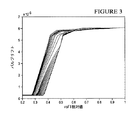
非限定的な例として、図3は、バルブ流量モデル300の一例を示し、図4は、バルブ力対リフトモデル400を示し、図5は、バルブヒステリシスモデル500(与圧なし)の一例を示している。 As a non-limiting example, FIG. 3 shows an example of a valve flow model 300, FIG. 4 shows a valve force versus lift model 400, and FIG. 5 shows an example of a valve hysteresis model 500 (no pressurization). ing.
図6は、開示した実施形態による質量流量制御器の様々な構成要素のモデルを利用するモデルベースの制御ループ600の一例を示す流れ図である。このモデルベースの制御ループ600は、特定の用途/条件ごとにチューニングを必要とすることなく様々な条件下でデバイスに対する自動最適応答を提供するように、質量流量制御器のコントローラーにおいて実施することができる。
FIG. 6 is a flow diagram illustrating an example of a model-based
PID制御ループ200と同様に、モデルベースの制御ループ600は、ステップ602において、温度を測定して流体路に沿った温度を求めることによって開始する。ステップ604において、モデルベースの制御ループ600は、圧力トランスデューサーを用いて圧力を測定する。モデルベースの制御ループ600は、ステップ606において、流量計を用いて流量を測定する。ステップ608において、モデルベースの制御ループ600は設定点を取得する。
Similar to the
ステップ610において、モデルベースの制御ループ600は、図3に示すようなバルブ流量モデルを用いて流量設定点を達成するのに必要とされるバルブリフトを求める計算を実行する。このバルブ流量モデルは、質量流量制御器内に書き込まれる固定係数を計算する製造ソフトウェアで実施される。1つの実施形態では、このアルゴリズムは、質量流量制御器自体の内部に実装され、リアルタイムで実行される。
In step 610, the model-based
1つの実施態様では、バルブ流量モデル300を生成する際に、種々の流入口圧力および流出口圧力における流体の流量が、主に粘性圧力降下および非粘性(動的)圧力降下の2つの構成要素からなるように物理的にモデル化される。各構成要素についてのバルブの有効変位が等しい場合のこれらの構成要素のそれぞれの寄与を合計することによって、バルブの有効変位は、以下の方法論を用いて実験的に求めることができる。特定の流体に関する特定の流体流量率におけるバルブの有効変位を求めることによって、バルブに関連付けられた利得項を求めることが可能になり、従って、バルブアクチュエーターに関連付けられた利得項を求めることが可能になる。 In one embodiment, when generating the valve flow model 300, the flow rate of the fluid at various inlet and outlet pressures is mainly divided into two components: a viscous pressure drop and an inviscid (dynamic) pressure drop. Is physically modeled as follows. By summing the contributions of each of these components when the effective displacement of the valve for each component is equal, the effective displacement of the valve can be determined experimentally using the following methodology. By determining the effective displacement of the valve at a specific fluid flow rate for a specific fluid, it is possible to determine the gain term associated with the valve, and therefore the gain term associated with the valve actuator. Become.
一般に、モデルベースの制御ループ600の一部である各構成要素は、関連付けられた利得を有することができる。利得という用語は、特定の構成要素または一群の構成要素の入力と出力との間の関係を指す。例えば、利得は、入力の変化に対する出力の変化の比を表すことができる。利得は、1または複数の変数、例えば、質量流量制御器の1または複数の動作条件および/または特性(例えば、流量率、流入口圧力および/または流出口圧力、温度、バルブ変位等)の関数とすることができる。一般に、そのような利得関数は、利得項と呼ばれる。利得項、より詳細には利得項を表すものは、曲線、関数のサンプル、離散データ点、点対、定数等とすることができる。
In general, each component that is part of the model-based
1つの実施形態では、上流の圧力または流入口圧力をP1によって表すものとし、下流の圧力または流出口圧力をP2によって表すものとすると、Qによって表される質量流量において、バルブリフトはHによって表され、粘性効果のみが圧力をP1から或る中間圧力Pxに低減する。非粘性圧縮性流が、圧力を中間圧力PxからP2に更に低減する。2つの平行板の間(例えば、バルブシートとジェット面との間)における流体の粘性流の物理モデルに基づいてバルブ170両端における粘性圧力降下をモデル化すると、これらの2つの平行板の間の距離H(例えば、バルブ170の変位)は、以下の式によって提供される。

P1、Px:粘性表面の上流および下流の圧力(psi)である。
Q:質量流量(標準CC/min)である。
L:流路の長さ(ft)である。
H:2つの平行な表面間の距離(ft)である。
w:流路の幅である。wはπ・φに等しく、φはプラトー(plateau)の平均直径であり、φは試験されたバルブに基づくと0.040”に等しい。
μ:気体の動的粘度(センチポアズ)である。
T:絶対温度(ランキン度)である。
R:気体定数(ft-lbf/lbm−ランキン度)である
In one embodiment, where the upstream pressure or inlet pressure is represented by P 1 and the downstream pressure or outlet pressure is represented by P 2 , at a mass flow rate represented by Q, the valve lift is H The only viscous effect reduces the pressure from P 1 to some intermediate pressure P x . Inviscid compressible flow further reduces the P 2 pressure from intermediate pressure P x. Modeling the viscous pressure drop across the
P 1 , P x : pressures (psi) upstream and downstream of the viscous surface.
Q: Mass flow rate (standard CC / min).
L: length of channel (ft).
H: distance (ft) between two parallel surfaces.
w: width of the flow path. w is equal to π · φ, φ is the average diameter of the plateau, and φ is equal to 0.040 ″ based on the valve tested.
μ: Gas dynamic viscosity (centipoise).
T: Absolute temperature (Rankine degree).
R: Gas constant (ft-lbf / lbm-Rankine degree)
オリフィスまたは噴出孔を通る流体の非粘性流の物理モデルに基づいてバルブ170の両端における非粘性圧力降下をモデル化することによって、以下の式が提供される。チョーク流の場合には、以下の式となる。
ここで、
Q=バルブを通る流量(標準CC/min)である。
A=π・φ・H=バルブ有効面積(平方インチ)である。
φ=オリフィスの直径である。
Mw=気体分子量(グラム/モル)である。
Px,0=上流の総圧力(torr)である。
P2=下流の静的圧力(torr)である。
T1,0=気体温度(K)である。
γ=比熱比である。
here,
Q = flow rate through the valve (standard CC / min).
A = π · φ · H = valve effective area (square inch).
φ = orifice diameter.
M w = gas molecular weight (grams / mole).
P x, 0 = upstream total pressure (torr).
P 2 = downstream static pressure (torr).
T 1,0 = gas temperature (K).
γ = specific heat ratio.
上記粘性式および非粘性式から、バルブ170の有効変位(すなわち、H)を容易に求めることができる。有効変位を計算する1つの例示の方法は、試行錯誤によって中間圧力Pxを推定することである。この場合、Hの値は、粘性流理論(Hv、式1)と、流れがチョークされているか否か(式4)に応じた非粘性理論(Hi、式2または式3)との双方から計算される。従って、中間圧力が流出口圧力のほぼ2倍である場合には、チョーク流を仮定することができ、式2が計算の非粘性構成要素に用いられるのに対して、流入口圧力が流出口圧力のほぼ2倍未満である場合には、式3が計算の非粘性構成要素に用いられる。所与のQ、P1およびP2について、粘性バルブリフト(Hv)および非粘性バルブリフト(Hi)が互いに等しくなるとき、正しいPxが取得される。従って、この計算方式は、Pxを取得する連続した反復を伴う。この計算は、Pxを、P1とP2との中程になるように選ぶことによって開始する。次に、HvおよびHiが計算される。HvがHiよりも大きいと判断された場合、これは、粘性流が、非粘性流に比べて、必要とされる流量を送達するのに十分な差圧がないことを意味し、次の反復中に、より低い圧力Px’が、すなわち、下流の圧力P2と前の圧力Pxとの間において選ばれることになる。この反復は、2つの計算されたバルブリフトHvおよびHiが互いの或る閾値内に入るまで継続する。上述したように、この反復プロセスは、質量流量制御器自体の内部に実装されたソフトウェアで実行することができ、リアルタイムで実行することができる。従って、上記方法に基づくと、バルブ170の有効変位を、複数の異なる流量率のそれぞれについて求めることができる。
The effective displacement (that is, H) of the
異なるバルブおよびバルブタイプは異なる物理モデルを有する場合があることが認識されるべきである。さらに、任意の特定のバルブの特性をモデル化するのに用いることができる物理モデルは2つ以上存在し得る。従って、本発明は、どの特定のバルブモデルにも限定されるものではない。 It should be appreciated that different valves and valve types may have different physical models. In addition, there can be more than one physical model that can be used to model the characteristics of any particular valve. Thus, the present invention is not limited to any particular valve model.
図6を再び参照すると、モデルベースの制御ループ600は、ステップ612において、リフト対力モデルを用いて上記リフトを生成するのに必要とされる力を計算する。このリフト対力モデルは、図4に示すリフト対力モデル400等であるが、これらに限定されるものではない。1つの実施形態では、リフト対力モデルは、力の平衡式:F=kx+deltaP*Aに基づいている。ここで、kは、バルブのばね定数と等価なものであり、xは、変位の量であり、deltaPは、バルブの両端における圧力差であり、Aは、圧力差に暴露されたバルブシートの表面積に等しい。
Referring again to FIG. 6, the model-based
モデルベースの制御ループ600は、次に、ステップ614において、バルブヒステリシスモデルを用いて上記力を生成するのに必要とされる駆動を計算する。このバルブヒステリシスモデルは、バルブヒステリシスモデル500等であるが、これらに限定されるものではない。モデルベースの制御ループ600は、ステップ616において、計算された駆動を用いて、バルブ制御信号をバルブに印加し、バルブを必要とされる位置に移動させる。モデルベースの制御ループ600は、その後、繰り返される。
The model-based
1つの実施形態では、ステップ614におけるバルブヒステリシスモデルは、従来のプライザッハモデルを利用した質量流量制御器内部のソフトウェアまたはファームウェアとして実装される。このプライザッハモデルは、力の量をアクチュエーター駆動の関数としてモデル化することによって、電磁アクチュエーターまたはピエゾアクチュエーターのヒステリシス特性の非線形性を捉えるのに用いられる。プライザッハモデルの主要な要素は、力の変化を経時的なバルブ駆動力の履歴の関数として考慮する力対バルブ駆動力表面マップMsである。プライザッハ関数P(U,V)は、磁性材料内の全てのヒステロン(hysterons)の密度関数である。総磁化は、以下の式によって表される。
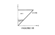
磁化は、プライザッハ平面上に表すことができる。例えば、図8は、プライザッハ平面上に表される表面マップ800の初期状態を示している。この初期状態は、全てのヒステロンが−1状態にある(すなわち、表面マップ800が完全に不活性である)ものと仮定されている。図8において、Uは、バルブ駆動力を表し、Vは、所与のリフトに必要とされる力を表し、m=−1は、不活性な表面エリアである。1つの実施形態では、Uは、Vよりも大きいものと仮定され、従って、三角形のみが、システム全体を表すのに必要とされる。磁場を単調に増加させた後、少数のヒステロン(低い感度を有するヒステロン)は、自身の磁化を−1から+1に切り替える(m=+1は、活性である表面エリアである)。これは、図9において、三角形の底部における小さなエリアによって表されている。磁場が増加し続けると、より多くのヒステロンが、図10に示す+1磁化に切り替わる。 The magnetization can be expressed on the Preisach plane. For example, FIG. 8 shows an initial state of a surface map 800 represented on the Preisach plane. This initial state is assumed that all hysterones are in the -1 state (ie, the surface map 800 is completely inactive). In FIG. 8, U represents the valve driving force, V represents the force required for a given lift, and m = −1 is an inert surface area. In one embodiment, U is assumed to be greater than V, so only triangles are needed to represent the entire system. After monotonically increasing the magnetic field, a small number of hysterones (hysterones with low sensitivity) switch their magnetization from -1 to +1 (m = + 1 is the active surface area). This is represented in FIG. 9 by a small area at the bottom of the triangle. As the magnetic field continues to increase, more hysterone switches to the +1 magnetization shown in FIG.
活性表面エリアを積分することによって、開示した実施形態は、バルブアクチュエーター力を経時的なバルブ駆動力の関数として追跡することができる。言い換えると、この動的な表面マップは、ヒステリシスの状態を前の全ての位置の関数として有するライブテーブルである。例えば、図7は、ヒステリシスの状態を前の全てのバルブ位置の関数として示す表面マップを動的に生成および更新するためのプロセス700を示している。1つの実施形態では、質量流量制御器に電源が投入された後、プロセス700は、ステップ702において始動される。プロセス700は、MFC制御アルゴリズムがゼロ設定点を受け取り、バルブがオフにされるごとに始動することもできる。
By integrating the active surface area, the disclosed embodiments can track valve actuator force as a function of valve driving force over time. In other words, this dynamic surface map is a live table that has a state of hysteresis as a function of all previous positions. For example, FIG. 7 shows a process 700 for dynamically generating and updating a surface map that shows the state of hysteresis as a function of all previous valve positions. In one embodiment, the process 700 is started at
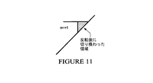
プロセス700は、ステップ704において、入力として望ましい力を受け取る更新関数をコールする。ステップ706において、プロセスは、望ましい力が現在の力よりも大きいのかまたは小さいのかを判断する。プロセスは、ステップ706において、望ましい力が現在の力よりも小さいと判断した場合、ステップ708において、値Vd_downを現在の駆動から差し引く。ステップ710において、プロセスは、図11に示すように、表面マップの一時コピーを更新し、新たな力を計算する。プロセスは、ステップ712において、この新たな力が望ましい力以下であるか否かを判断する。プロセスは、この新たな力が望ましい力以下でないと判断した場合、新たな力が望ましい力以下でなくなるまで、ステップ708において、値Vd_downを現在の駆動から差し引くことによって当該プロセスを繰り返す。新たな力が望ましい力以下になると、プロセスは、ステップ720において、実際の表面マップを更新し、必要とされるバルブ駆動力値を出力する。
Process 700 calls an update function that receives the desired force as input at step 704. In step 706, the process determines whether the desired force is greater or less than the current force. If the process determines in step 706 that the desired force is less than the current force, then in
一方、プロセスは、ステップ706において、望ましい力が現在の力よりも大きいと判断した場合、ステップ714において、値Vd_upを現在の駆動に加える。ステップ716において、プロセスは、図12に示すように、表面マップの一時コピーを更新し、新たな力を計算する。プロセスは、ステップ718において、この新たな力が望ましい力以上であるか否かを判断する。プロセスは、この新たな力が望ましい力以上でないと判断した場合、新たな力が望ましい力以上でなくなるまで、ステップ714において、値Vd_downを現在の駆動に加えることによって当該プロセスを繰り返す。新たな力が望ましい力以上になると、プロセスは、ステップ720において、実際の表面マップを更新し、必要とされるバルブ駆動力値を出力する。図13は、上記プロセスを用いた複数回の反復後の表面マップの一例を示している。プロセス700は、新たな望ましい力が取得されるごとに繰り返される。
On the other hand, if the process determines in step 706 that the desired force is greater than the current force, then in
1つの実施形態では、以下の離散行列が、上記に示した式5を表すのに用いられる。
この行列のあらゆる列が、異なるバルブ駆動力を表している。バルブ駆動力の分解能は、行列のサイズを決定する。例えば、1%の分解能は、100×M行列を必要とする。行は、駆動からもたられる力である。この行列は正方形である必要はなく、そのため、Mは100よりも小さくすることもできるし、大きくすることもできることに留意されたい。バルブ駆動力が上下すると、行列のセルは、交互に1および0になり、図13に示すような活性/不活性表面マップを作成する。 Every column of this matrix represents a different valve driving force. The resolution of the valve driving force determines the size of the matrix. For example, 1% resolution requires a 100 × M matrix. Row is the force that comes from driving. Note that this matrix need not be square, so M can be smaller or larger than 100. As the valve driving force rises and falls, the cells of the matrix alternate between 1 and 0, creating an active / inactive surface map as shown in FIG.
或る特定の実施形態では、プロセス700は、「不動帯」、並びに例えば流入口圧力、温度または気体特性に基づいてVd_upおよびVd_downの値を調節するためのステップを実施することができる。 In certain embodiments, the process 700 may perform steps for adjusting the values of Vd_up and Vd_down based on “dead zone” and, for example, inlet pressure, temperature, or gas characteristics.
代替の実施形態では、アルゴリズムの計算要件およびメモリ要件を低減するために、プライザッハマップにおける最大変曲点および最小変曲点の経過のみを追跡するようにプロセス700を変更することができる。プライザッハマップは、次に、反転されて、所与の力を生成するのに必要とされる所要の駆動が取得される。更に、代替の実施形態は、ヒステリシス効果の他の数学モデルを実施することができる。これらの他の数学モデルは、チューア(Chua)およびストロズモー(Stromsmoe)のモデル、ジルズ(Jiles)およびアサートン(Atherton)のモデルまたはカーノップ(Karnopp)のモデル等であるが、これらに限定されるものではない。 In an alternative embodiment, the process 700 can be modified to track only the course of the maximum and minimum inflection points in the Preisach map to reduce the computational and memory requirements of the algorithm. The Preisach map is then inverted to obtain the required drive needed to generate a given force. Furthermore, alternative embodiments can implement other mathematical models of hysteresis effects. These other mathematical models include, but are not limited to, Chua and Stromsmoe models, Jiles and Atherton models or Karnopp models. Absent.
さらに、別の実施形態では、モデルベースの質量流量制御器は、図2において前述したようなPID制御を利用することができ、PIDの外部の制御変数が、ヒステリシスモデルが駆動に変換する力である(PIDの外部の制御変数が駆動であること、すなわちステップ220とは対照的である)ヒステリシスモデルを追加することができる。これによって、制御システムにおいてヒステリシスが大幅に低減されるという利点がもたらされ、さらに、これによって、乱れからの回復が高速化される。 Furthermore, in another embodiment, the model-based mass flow controller can utilize PID control as previously described in FIG. 2, where the control variable outside the PID is the force that the hysteresis model converts to drive. A hysteresis model can be added (as opposed to a control variable outside the PID, ie, step 220). This has the advantage that the hysteresis is greatly reduced in the control system, which further speeds up the recovery from disturbances.
従って、上記に説明したように、開示した実施形態の利点には、特定の用途/条件ごとにチューニングを必要とすることなく様々な条件下でデバイスに対する自動最適応答を可能にするように構成されたモデルベースのコントローラーを質量流量制御器に設けることが含まれるが、これに限定されるものではない。 Thus, as described above, the advantages of the disclosed embodiments are configured to allow an automatic optimal response to the device under various conditions without requiring tuning for each specific application / condition. Including, but not limited to, providing a model-based controller in the mass flow controller.
上記実施形態についての具体的な詳細を説明してきたが、上記ハードウェアおよびソフトウェアの説明は、単なる例示の実施形態として意図されているにすぎず、開示した実施形態の構造も実施態様も限定するように意図されていない。 Although specific details of the above embodiments have been described, the above description of hardware and software is intended as exemplary embodiments only and limits the structure and implementation of the disclosed embodiments. Not intended to be.
更に、開示した実施形態の或る特定の態様は、上記で概説したように、1または複数の処理ユニット/構成要素を用いて実行されるソフトウェアに具現化することができる。この技術のプログラムの態様は、通常は或るタイプの機械可読媒体上に担持されるかまたはその機械可読媒体に具現化される実行可能コードおよび/または関連データの形態の「製品」または「製造物品」と考えることができる。有形の非一時的な「記憶装置」型媒体には、ソフトウェアプログラミング用にいつでも記憶装置を提供することができる、様々な半導体メモリ、テープドライブ、ディスクドライブ、光ディスクまたは磁気ディスク等の、コンピューター、プロセッサ等またはそれらの関連モジュールのためのメモリまたは他の記憶装置のうちの任意のものまたはそれらの全てが含まれる。 Furthermore, certain aspects of the disclosed embodiments can be embodied in software executed using one or more processing units / components, as outlined above. Program aspects of this technology are typically “product” or “manufacturing” in the form of executable code and / or associated data carried on or embodied in a certain type of machine-readable medium. Can be thought of as an article. Tangible non-transitory "storage device" type media include computers, processors, such as various semiconductor memories, tape drives, disk drives, optical disks or magnetic disks, which can provide storage at any time for software programming Etc. or any or all of their memory or other storage for their associated modules.
当業者であれば、本教示が、様々な変更形態および/または強化形態に適用可能であることを認識するであろう。上記内容は最良の形態とみなされるものおよび/または他の例を説明しているが、様々な変更をそれらに行うことができること、本明細書に開示した主題は様々な形態および例で実施することができること、並びにそれらの教示は多数の用途において適用することができ、それらの用途の一部しか本明細書に説明されていないことが理解される。そのような変更は、本教示の真の範囲内に包含されるように意図されている。 Those skilled in the art will recognize that the present teachings are applicable to various modifications and / or enhancements. Although the foregoing describes what is considered to be the best mode and / or other examples, various modifications can be made to them, and the subject matter disclosed herein can be implemented in various forms and examples It is understood that the teachings can be applied in a number of applications, and only some of those applications are described herein. Such modifications are intended to be included within the true scope of the present teachings.
更に、図におけるフローチャートおよびブロック図は、本発明の様々な実施形態によるシステム、方法およびコンピュータープログラム製品の可能な実施態様のアーキテクチャ、機能および動作を示している。幾つかの代替の実施態様では、ブロックに示された機能は、図に示された順序以外で行うことができることにも留意すべきである。例えば、連続して示された2つのブロックは、含まれる機能に応じて、実際には、実質的に同時に実行される場合もあるし、それらのブロックは、時に、逆の順序で実行される場合もある。ブロック図および/またはフローチャート説明図の各ブロック、並びにブロック図および/またはフローチャート説明図におけるブロックの組み合わせは、指定された機能若しくは動作を実行する専用ハードウェアベースのシステムまたは専用ハードウェアおよびコンピューター命令の組み合わせによって実施することができることにも留意されるであろう。 Furthermore, the flowcharts and block diagrams in the Figures illustrate the architecture, functionality, and operation of possible implementations of systems, methods and computer program products according to various embodiments of the present invention. It should also be noted that in some alternative embodiments, the functions shown in the blocks can be performed out of the order shown in the figures. For example, two blocks shown in succession may actually be executed substantially simultaneously, depending on the functions involved, and sometimes they are executed in reverse order. In some cases. Each block of the block diagrams and / or flowchart illustrations, and combinations of blocks in the block diagrams and / or flowchart illustrations, are dedicated hardware-based systems or dedicated hardware and computer instructions that perform specified functions or operations. It will also be noted that it can be implemented in combination.
本明細書に用いられる術語は、特定の実施形態を説明するためだけのものであり、本発明の限定であるように意図されていない。数量が特定されていない記載は、本明細書において用いられるとき、文脈が複数形を含まないことを明確に示していない限り、複数形も同様に含むように意図されている。「具備する」という用語は、この明細書および/または特許請求の範囲において用いられるとき、明記した特徴、完全体、ステップ、動作、要素および/または構成要素が存在することを明示しているが、1または複数の他の特徴、完全体、ステップ、動作、要素、構成要素および/またはそれらの群が存在することまたは追加されることを排除していないことが更に理解されるであろう。添付の特許請求の範囲における全ての手段またはステップに機能を加えた要素の対応する構造、材料、動作および均等物は、その機能を、具体的に請求項に記載されている他の請求項に記載の要素と組み合わせて実行するための任意の構造、材料または動作を含むように意図されている。本発明の説明は、例示および説明の目的で提示されており、網羅的であることも、開示した形態の発明に限定されることも意図するものではない。本発明の範囲および趣旨から逸脱することなく、多くの変更形態および変形形態が当業者に明らかであろう。実施形態は、本発明の原理および実用的な用途を説明するとともに、他の当業者が、考慮されている特定の使用に適するように様々な変更を有する様々な実施形態について本発明を理解することを可能にするために選ばれて記載されている。請求項の範囲は、開示した実施形態および任意のそのような変更を広く包含するように意図されている。 The terminology used herein is for the purpose of describing particular embodiments only and is not intended to be limiting of the invention. Descriptions that do not specify quantities are intended to include the plural as well, unless the context clearly indicates that the plural is not included, as used herein. The term “comprising”, as used in this specification and / or claims, specifies that a specified feature, completeness, step, action, element, and / or component exists. It will be further understood that one or more other features, completeness, steps, actions, elements, components and / or groups thereof are not excluded or added. Corresponding structures, materials, acts and equivalents of an element added function to all means or steps in the appended claims are subject to reference to the other claims specifically recited in the claim. It is intended to include any structure, material, or operation for performing in combination with the elements described. The description of the present invention has been presented for purposes of illustration and description, and is not intended to be exhaustive or limited to the invention in the form disclosed. Many modifications and variations will be apparent to those skilled in the art without departing from the scope and spirit of the invention. The embodiments illustrate the principles and practical applications of the present invention, and others skilled in the art will understand the present invention for various embodiments with various modifications to suit the particular use considered. It is chosen and described to make it possible. The scope of the claims is intended to broadly encompass the disclosed embodiments and any such modifications.
100 質量流量制御器
102 センサーハウジング
108 基部
110 ステップ
112 圧力トランスデューサー
120 流体流入口
130 流体流出口
140 熱式質量流量計
142 バイパス
146 熱式流量センサー
146A センサー流入口部分
146B センサー流出口部分
146C センサー測定部分
147 抵抗器
148 抵抗器
150 制御バルブアセンブリ
158 電気導体
160 閉ループシステムコントローラー
170 制御バルブ
200 制御ループ
300 バルブ流量モデル
400 バルブ力対リフトモデル
400 リフト対力モデル
500 バルブヒステリシスモデル
600 制御ループ
100 Mass Flow Controller 102
Claims (2)
前記流体を受け取るための流入口と、
前記流体が該質量流量制御器を通過する流路と、
前記流路を通る前記流体の質量流量に対応する信号を提供する質量流量計と、
該質量流量制御器の流出口から流出する前記流体の前記流量を調節するための調節可能バルブと、
プライザッハモデルを利用するバルブヒステリシスモデルを用いて、所与の流量設定点に基づいて望ましいバルブ位置に前記調節可能バルブを移動させるためのバルブリフトを達成する力を生成するのに必要なバルブ駆動力を求める命令を実行するように構成された少なくとも1つの処理構成要素と、
前記求められたバルブ駆動力に基づいてバルブ制御信号を与えて、前記調節可能バルブを前記望ましいバルブ位置に調節し、該質量流量制御器の流出口から流出する前記流体の前記流量を制御するように構成されたコントローラーとを具備する流体の流量を制御するための質量流量制御器。 In a mass flow controller for controlling the flow rate of fluid,
An inlet for receiving the fluid;
A flow path through which the fluid passes through the mass flow controller;
A mass flow meter providing a signal corresponding to the mass flow rate of the fluid through the flow path;
An adjustable valve for adjusting the flow rate of the fluid flowing out of the outlet of the mass flow controller;
Using a valve hysteresis model that utilizes the Preisach model, the valve drive required to generate the force to achieve the valve lift to move the adjustable valve to the desired valve position based on a given flow set point At least one processing component configured to execute instructions for determining force;
A valve control signal is provided based on the determined valve driving force to adjust the adjustable valve to the desired valve position to control the flow rate of the fluid flowing out of the outlet of the mass flow controller. A mass flow controller for controlling the flow rate of the fluid, comprising a controller configured as described above.
所与の流量設定点に基づく望ましいバルブ位置に調節可能バルブを移動させるためのバルブリフトを達成する力を生成するのに必要なバルブ駆動力を、プライザッハモデルを利用するバルブヒステリシスモデルに基づいて求めることと、
プロセッサを用いて、前記求められたバルブ駆動力に基づくバルブ制御信号を与えることであって、前記望ましいバルブ位置に前記調節可能バルブを調節して前記流体の前記流量を制御することとを含む流体の流量を制御するための方法。 A method for controlling the flow rate of a fluid, comprising:
Based on the valve hysteresis model using the Preisach model , the valve driving force required to generate the force to achieve the valve lift to move the adjustable valve to the desired valve position based on a given flow set point Seeking and
Using a processor to provide a valve control signal based on the determined valve driving force, including adjusting the adjustable valve to the desired valve position to control the flow rate of the fluid Method for controlling the flow rate of the water.
Applications Claiming Priority (3)
| Application Number | Priority Date | Filing Date | Title |
|---|---|---|---|
| US201261607944P | 2012-03-07 | 2012-03-07 | |
| US61/607,944 | 2012-03-07 | ||
| PCT/US2013/028902 WO2013134141A2 (en) | 2012-03-07 | 2013-03-04 | System and mehtod for using a model for improving control of a mass flow controller |
Related Child Applications (1)
| Application Number | Title | Priority Date | Filing Date |
|---|---|---|---|
| JP2018100354A Division JP6691167B2 (en) | 2012-03-07 | 2018-05-25 | Mass flow controller and method for controlling fluid flow rate |
Publications (3)
| Publication Number | Publication Date |
|---|---|
| JP2015510207A JP2015510207A (en) | 2015-04-02 |
| JP2015510207A5 JP2015510207A5 (en) | 2016-04-21 |
| JP6563656B2 true JP6563656B2 (en) | 2019-08-21 |
Family
ID=49117492
Family Applications (2)
| Application Number | Title | Priority Date | Filing Date |
|---|---|---|---|
| JP2014560998A Active JP6563656B2 (en) | 2012-03-07 | 2013-03-04 | System and method for using a model to improve control of a mass flow controller |
| JP2018100354A Active JP6691167B2 (en) | 2012-03-07 | 2018-05-25 | Mass flow controller and method for controlling fluid flow rate |
Family Applications After (1)
| Application Number | Title | Priority Date | Filing Date |
|---|---|---|---|
| JP2018100354A Active JP6691167B2 (en) | 2012-03-07 | 2018-05-25 | Mass flow controller and method for controlling fluid flow rate |
Country Status (3)
| Country | Link |
|---|---|
| US (1) | US9760096B2 (en) |
| JP (2) | JP6563656B2 (en) |
| WO (1) | WO2013134141A2 (en) |
Families Citing this family (11)
| Publication number | Priority date | Publication date | Assignee | Title |
|---|---|---|---|---|
| US9471066B2 (en) | 2012-01-20 | 2016-10-18 | Mks Instruments, Inc. | System for and method of providing pressure insensitive self verifying mass flow controller |
| US9557744B2 (en) | 2012-01-20 | 2017-01-31 | Mks Instruments, Inc. | System for and method of monitoring flow through mass flow controllers in real time |
| US9846074B2 (en) | 2012-01-20 | 2017-12-19 | Mks Instruments, Inc. | System for and method of monitoring flow through mass flow controllers in real time |
| US10031005B2 (en) | 2012-09-25 | 2018-07-24 | Mks Instruments, Inc. | Method and apparatus for self verification of pressure-based mass flow controllers |
| EP3105647B1 (en) * | 2014-02-13 | 2019-01-23 | MKS Instruments, Inc. | System for and method of providing pressure insensitive self verifying mass flow controller |
| JP6781758B2 (en) | 2015-08-31 | 2020-11-04 | エム ケー エス インストルメンツ インコーポレーテッドMks Instruments,Incorporated | Systems for pressure flow measurement, non-temporary machine-readable media and methods of pressure flow control |
| KR102339509B1 (en) * | 2015-09-11 | 2021-12-16 | 히타치 긴조쿠 가부시키가이샤 | mass flow control unit |
| US10969797B2 (en) | 2018-08-29 | 2021-04-06 | Illinois Tool Works, Inc. | Mass flow valve controller and control method with set point filter and linearization system based on valve model |
| US10705543B2 (en) * | 2018-08-29 | 2020-07-07 | Illinois Tool Works, Inc. | Mass flow controller and controller algorithm |
| JP2021152786A (en) * | 2020-03-24 | 2021-09-30 | 株式会社フジキン | Flow rate control system, control method for flow rate control system, control program for flow rate control system |
| CN114488785B (en) * | 2021-08-09 | 2023-11-14 | 宁波大学 | MFC actuator track tracking method |
Family Cites Families (22)
| Publication number | Priority date | Publication date | Assignee | Title |
|---|---|---|---|---|
| DE4432109C1 (en) * | 1994-09-09 | 1996-03-21 | Bizerba Gmbh & Co Kg | Weighing device |
| US5911238A (en) * | 1996-10-04 | 1999-06-15 | Emerson Electric Co. | Thermal mass flowmeter and mass flow controller, flowmetering system and method |
| US6389364B1 (en) | 1999-07-10 | 2002-05-14 | Mykrolis Corporation | System and method for a digital mass flow controller |
| JP3417391B2 (en) | 2000-09-07 | 2003-06-16 | 日立金属株式会社 | Flow control method |
| JP2002127003A (en) * | 2000-10-26 | 2002-05-08 | Hiroshi Eda | Precision machining device with attitude control device and attitude control method |
| JP4571322B2 (en) * | 2001-03-05 | 2010-10-27 | 佐藤 ▼壽▲芳 | Analysis method of non-linear restoring force characteristics with mechanical structure history |
| AU2002307547A1 (en) * | 2001-04-24 | 2002-11-05 | Unit Instruments, Inc. | System and method for configuring and asapting a mass flow controller |
| US6766241B2 (en) * | 2001-12-26 | 2004-07-20 | Deere & Company | Fuel injection control system |
| JP4219600B2 (en) * | 2002-02-28 | 2009-02-04 | 株式会社アドヴィックス | Brake hydraulic pressure generator for vehicles |
| EP1523701A2 (en) * | 2002-07-19 | 2005-04-20 | Celerity Group, Inc. | Methods and apparatus for pressure compensation in a mass flow controller |
| US7054773B2 (en) * | 2003-05-30 | 2006-05-30 | Agilent Technologies, Inc. | Dynamic model-based compensated tuning of a tunable device |
| JP2007108925A (en) * | 2005-10-12 | 2007-04-26 | Toyota Motor Corp | Posture control system |
| US7250738B1 (en) * | 2006-07-12 | 2007-07-31 | Chung-Yuan Christian University | Nonlinear hysteresis control system |
| CA2842521C (en) * | 2007-04-24 | 2017-03-07 | Yale Security Inc. | Door closer assembly |
| US7957921B2 (en) * | 2008-02-19 | 2011-06-07 | GM Global Technology Operations LLC | Model-based estimation of battery hysteresis |
| US8671973B2 (en) | 2009-01-21 | 2014-03-18 | Hitachi Metals, Ltd. | Mass flow controller hysteresis compensation system and method |
| JP4802262B2 (en) * | 2009-02-17 | 2011-10-26 | ジヤトコ株式会社 | Hydraulic control device |
| US9482867B2 (en) | 2009-09-16 | 2016-11-01 | Bae Systems Plc | Compensating for hysteresis |
| US9058026B2 (en) * | 2009-09-16 | 2015-06-16 | Bae Systems Plc | Compensating for hysteresis |
| US8534135B2 (en) * | 2010-04-30 | 2013-09-17 | Nanometrics Incorporated | Local stress measurement |
| US20120197446A1 (en) * | 2010-12-01 | 2012-08-02 | Glaudel Stephen P | Advanced feed-forward valve-control for a mass flow controller |
| US20140195136A1 (en) * | 2011-09-20 | 2014-07-10 | Toyota Jidosha Kabushiki Kaisha | Control device of internal combustion engine |
-
2013
- 2013-03-04 WO PCT/US2013/028902 patent/WO2013134141A2/en active Application Filing
- 2013-03-04 US US14/378,527 patent/US9760096B2/en active Active
- 2013-03-04 JP JP2014560998A patent/JP6563656B2/en active Active
-
2018
- 2018-05-25 JP JP2018100354A patent/JP6691167B2/en active Active
Also Published As
| Publication number | Publication date |
|---|---|
| JP2018173963A (en) | 2018-11-08 |
| JP2015510207A (en) | 2015-04-02 |
| WO2013134141A2 (en) | 2013-09-12 |
| US20150039140A1 (en) | 2015-02-05 |
| JP6691167B2 (en) | 2020-04-28 |
| US9760096B2 (en) | 2017-09-12 |
| WO2013134141A8 (en) | 2013-12-19 |
| WO2013134141A3 (en) | 2014-02-20 |
Similar Documents
| Publication | Publication Date | Title |
|---|---|---|
| JP6691167B2 (en) | Mass flow controller and method for controlling fluid flow rate | |
| JP6415889B2 (en) | Flow control device, program for flow control device, and flow control method | |
| CN108227763B (en) | Flow rate control device and program storage medium | |
| KR102106825B1 (en) | Mass flow controller and method for improved performance across fluid types | |
| KR102371907B1 (en) | Gas flow control method and device | |
| US7380564B2 (en) | System and method for a mass flow controller | |
| WO2015151647A1 (en) | Mass flow rate measurement method, thermal mass flow rate meter using said method, and thermal mass flow rate controller using said thermal mass flow rate meter | |
| US20120197446A1 (en) | Advanced feed-forward valve-control for a mass flow controller | |
| US20190196517A1 (en) | Calibration data generation apparatus, calibration data generation method, and flow rate control device | |
| TWI684844B (en) | Self-diagnosis method of flow control device | |
| US10437264B2 (en) | System and method for improving the accuracy of a rate of decay measurement for real time correction in a mass flow controller or mass flow meter by using a thermal model to minimize thermally induced error in the rod measurement | |
| JP2020021176A (en) | Flow controller | |
| JP2019159687A (en) | Flow controller, flow control method, and program for flow controllers | |
| WO2016178739A1 (en) | Nonlinear control of mass flow controller devices using sliding mode | |
| JP6680669B2 (en) | System and method for automatically self-adjusting a valve pedestal of a mass flow controller | |
| JP2019105338A (en) | Fluid control device and program for fluid control device | |
| JP2012168824A (en) | Fluid control device | |
| EP1457856B1 (en) | Valve displacement determining method for a mass flow controller | |
| KR101889379B1 (en) | Liquid flow rate control system | |
| JP2012168822A (en) | Fluid control device |
Legal Events
| Date | Code | Title | Description |
|---|---|---|---|
| A521 | Request for written amendment filed |
Free format text: JAPANESE INTERMEDIATE CODE: A523 Effective date: 20160304 |
|
| A621 | Written request for application examination |
Free format text: JAPANESE INTERMEDIATE CODE: A621 Effective date: 20160304 |
|
| A977 | Report on retrieval |
Free format text: JAPANESE INTERMEDIATE CODE: A971007 Effective date: 20170327 |
|
| A131 | Notification of reasons for refusal |
Free format text: JAPANESE INTERMEDIATE CODE: A131 Effective date: 20170509 |
|
| A521 | Request for written amendment filed |
Free format text: JAPANESE INTERMEDIATE CODE: A523 Effective date: 20170803 |
|
| A02 | Decision of refusal |
Free format text: JAPANESE INTERMEDIATE CODE: A02 Effective date: 20180130 |
|
| A61 | First payment of annual fees (during grant procedure) |
Free format text: JAPANESE INTERMEDIATE CODE: A61 Effective date: 20190725 |
|
| R150 | Certificate of patent or registration of utility model |
Ref document number: 6563656 Country of ref document: JP Free format text: JAPANESE INTERMEDIATE CODE: R150 |
|
| R250 | Receipt of annual fees |
Free format text: JAPANESE INTERMEDIATE CODE: R250 |
|
| R250 | Receipt of annual fees |
Free format text: JAPANESE INTERMEDIATE CODE: R250 |