JP6563502B2 - Golf club with hosel insert and related method - Google Patents
Golf club with hosel insert and related method Download PDFInfo
- Publication number
- JP6563502B2 JP6563502B2 JP2017538682A JP2017538682A JP6563502B2 JP 6563502 B2 JP6563502 B2 JP 6563502B2 JP 2017538682 A JP2017538682 A JP 2017538682A JP 2017538682 A JP2017538682 A JP 2017538682A JP 6563502 B2 JP6563502 B2 JP 6563502B2
- Authority
- JP
- Japan
- Prior art keywords
- shaft sleeve
- shaft
- club head
- cap
- golf club
- Prior art date
- Legal status (The legal status is an assumption and is not a legal conclusion. Google has not performed a legal analysis and makes no representation as to the accuracy of the status listed.)
- Active
Links
- 238000000034 method Methods 0.000 title description 50
- 230000005484 gravity Effects 0.000 claims description 19
- 239000004033 plastic Substances 0.000 claims description 9
- 229920003023 plastic Polymers 0.000 claims description 9
- 229920000642 polymer Polymers 0.000 claims description 6
- 238000000354 decomposition reaction Methods 0.000 claims description 5
- 230000007246 mechanism Effects 0.000 description 70
- 230000008878 coupling Effects 0.000 description 60
- 238000010168 coupling process Methods 0.000 description 60
- 238000005859 coupling reaction Methods 0.000 description 60
- 230000000295 complement effect Effects 0.000 description 19
- 238000004519 manufacturing process Methods 0.000 description 18
- 230000008901 benefit Effects 0.000 description 14
- 239000000463 material Substances 0.000 description 12
- 230000007935 neutral effect Effects 0.000 description 8
- 230000000875 corresponding effect Effects 0.000 description 7
- 230000007423 decrease Effects 0.000 description 7
- 229910000838 Al alloy Inorganic materials 0.000 description 6
- 229910052782 aluminium Inorganic materials 0.000 description 6
- XAGFODPZIPBFFR-UHFFFAOYSA-N aluminium Chemical compound [Al] XAGFODPZIPBFFR-UHFFFAOYSA-N 0.000 description 6
- 239000002023 wood Substances 0.000 description 5
- 238000003780 insertion Methods 0.000 description 4
- 230000037431 insertion Effects 0.000 description 4
- 239000004593 Epoxy Substances 0.000 description 3
- 230000002093 peripheral effect Effects 0.000 description 3
- 230000008569 process Effects 0.000 description 3
- 239000007787 solid Substances 0.000 description 3
- 239000004677 Nylon Substances 0.000 description 2
- 229910000831 Steel Inorganic materials 0.000 description 2
- RTAQQCXQSZGOHL-UHFFFAOYSA-N Titanium Chemical compound [Ti] RTAQQCXQSZGOHL-UHFFFAOYSA-N 0.000 description 2
- 230000008859 change Effects 0.000 description 2
- 230000002596 correlated effect Effects 0.000 description 2
- 238000013016 damping Methods 0.000 description 2
- 229910052751 metal Inorganic materials 0.000 description 2
- 239000002184 metal Substances 0.000 description 2
- 229910001092 metal group alloy Inorganic materials 0.000 description 2
- 238000012986 modification Methods 0.000 description 2
- 230000004048 modification Effects 0.000 description 2
- 229920001778 nylon Polymers 0.000 description 2
- 230000009467 reduction Effects 0.000 description 2
- 239000010959 steel Substances 0.000 description 2
- 239000010936 titanium Substances 0.000 description 2
- 229910052719 titanium Inorganic materials 0.000 description 2
- 230000007704 transition Effects 0.000 description 2
- 239000004793 Polystyrene Substances 0.000 description 1
- BZHJMEDXRYGGRV-UHFFFAOYSA-N Vinyl chloride Chemical compound ClC=C BZHJMEDXRYGGRV-UHFFFAOYSA-N 0.000 description 1
- 239000000853 adhesive Substances 0.000 description 1
- 230000001070 adhesive effect Effects 0.000 description 1
- 229920001577 copolymer Polymers 0.000 description 1
- 238000013461 design Methods 0.000 description 1
- 238000011161 development Methods 0.000 description 1
- 230000018109 developmental process Effects 0.000 description 1
- 229920001971 elastomer Polymers 0.000 description 1
- 238000002386 leaching Methods 0.000 description 1
- 239000004417 polycarbonate Substances 0.000 description 1
- 229920000515 polycarbonate Polymers 0.000 description 1
- 229920000193 polymethacrylate Polymers 0.000 description 1
- 229920002223 polystyrene Polymers 0.000 description 1
- 239000004800 polyvinyl chloride Substances 0.000 description 1
- 229920000915 polyvinyl chloride Polymers 0.000 description 1
- 239000005060 rubber Substances 0.000 description 1
- 238000007789 sealing Methods 0.000 description 1
- 229920003051 synthetic elastomer Polymers 0.000 description 1
- 239000005061 synthetic rubber Substances 0.000 description 1
- 238000012360 testing method Methods 0.000 description 1
- 239000012815 thermoplastic material Substances 0.000 description 1
Images


Classifications
-
- A—HUMAN NECESSITIES
- A63—SPORTS; GAMES; AMUSEMENTS
- A63B—APPARATUS FOR PHYSICAL TRAINING, GYMNASTICS, SWIMMING, CLIMBING, OR FENCING; BALL GAMES; TRAINING EQUIPMENT
- A63B53/00—Golf clubs
- A63B53/02—Joint structures between the head and the shaft
-
- A—HUMAN NECESSITIES
- A63—SPORTS; GAMES; AMUSEMENTS
- A63B—APPARATUS FOR PHYSICAL TRAINING, GYMNASTICS, SWIMMING, CLIMBING, OR FENCING; BALL GAMES; TRAINING EQUIPMENT
- A63B53/00—Golf clubs
- A63B53/02—Joint structures between the head and the shaft
- A63B53/022—Joint structures between the head and the shaft allowing adjustable positioning of the head with respect to the shaft
- A63B53/023—Joint structures between the head and the shaft allowing adjustable positioning of the head with respect to the shaft adjustable angular orientation
-
- F—MECHANICAL ENGINEERING; LIGHTING; HEATING; WEAPONS; BLASTING
- F16—ENGINEERING ELEMENTS AND UNITS; GENERAL MEASURES FOR PRODUCING AND MAINTAINING EFFECTIVE FUNCTIONING OF MACHINES OR INSTALLATIONS; THERMAL INSULATION IN GENERAL
- F16B—DEVICES FOR FASTENING OR SECURING CONSTRUCTIONAL ELEMENTS OR MACHINE PARTS TOGETHER, e.g. NAILS, BOLTS, CIRCLIPS, CLAMPS, CLIPS OR WEDGES; JOINTS OR JOINTING
- F16B5/00—Joining sheets or plates, e.g. panels, to one another or to strips or bars parallel to them
- F16B5/02—Joining sheets or plates, e.g. panels, to one another or to strips or bars parallel to them by means of fastening members using screw-thread
-
- A—HUMAN NECESSITIES
- A63—SPORTS; GAMES; AMUSEMENTS
- A63B—APPARATUS FOR PHYSICAL TRAINING, GYMNASTICS, SWIMMING, CLIMBING, OR FENCING; BALL GAMES; TRAINING EQUIPMENT
- A63B2225/00—Miscellaneous features of sport apparatus, devices or equipment
- A63B2225/01—Special aerodynamic features, e.g. airfoil shapes, wings or air passages
Landscapes
- Health & Medical Sciences (AREA)
- General Health & Medical Sciences (AREA)
- Physical Education & Sports Medicine (AREA)
- Engineering & Computer Science (AREA)
- General Engineering & Computer Science (AREA)
- Mechanical Engineering (AREA)
- Golf Clubs (AREA)
Description
(関連出願の相互参照)
本出願は、2015年1月23日に出願の米国仮特許出願第62/107,240号明細書、2015年11月11日に出願の米国仮特許出願第62/254,081号明細書の利益を主張し、且つ2014年5月20日に出願の米国特許出願第14/282,786号明細書の一部継続出願である。米国特許出願第14/282,786号明細書は、(i)2013年3月12日に出願の米国特許出願第13/795,653号明細書、(ii)2012年3月24日に出願の米国特許出願第13/429,319号明細書、(iii)2012年5月10日に出願の米国特許出願第13/468,663号明細書、(iv)2012年5月10日に出願の米国特許出願第13/468,675号明細書、及び(v)2013年1月7日に出願の米国特許出願第13/735,123号明細書の一部継続出願である。
(Cross-reference of related applications)
This application is based on US Provisional Patent Application No. 62 / 107,240 filed on January 23, 2015, and US Provisional Patent Application No. 62 / 254,081 filed on November 11, 2015. This is a continuation-in-part of US patent application Ser. No. 14 / 282,786, which claims benefit and is filed May 20, 2014. US patent application Ser. No. 14 / 282,786 is filed with (i) US patent application Ser. No. 13 / 795,653 filed on Mar. 12, 2013, and (ii) filed Mar. 24, 2012. No. 13 / 429,319, (iii) U.S. Patent Application No. 13 / 468,663, filed May 10, 2012, (iv) filed May 10, 2012 US patent application Ser. No. 13 / 468,675 and (v) US patent application Ser. No. 13 / 735,123 filed Jan. 7, 2013.
米国特許出願第13/429,319号明細書は、2012年1月24日に出願の米国仮特許出願第61/590,232号明細書、及び2011年8月31日に出願の米国仮特許出願第61/529,880号明細書の利益を主張する。また、米国特許出願第13/468,663号明細書、及び米国特許出願第13/468,675号明細書は、それぞれ米国特許出願第13/429,319号明細書の一部継続出願である。同様に、米国特許出願第13/468,677号明細書は、米国特許出願第13/429,319号明細書の継続出願である。 US Patent Application No. 13 / 429,319 includes US Provisional Patent Application No. 61 / 590,232, filed January 24, 2012, and US Provisional Patent, filed August 31, 2011. Claims the benefit of application 61 / 529,880. In addition, U.S. Patent Application No. 13 / 468,663 and U.S. Patent Application No. 13 / 468,675 are partially continued applications of U.S. Patent Application No. 13 / 429,319, respectively. . Similarly, U.S. Patent Application No. 13 / 468,677 is a continuation of U.S. Patent Application No. 13 / 429,319.
一方、米国特許出願第13/735,123号明細書は、2012年5月10日に出願の米国特許出願第13/468,663号明細書、2012年5月10日に出願の米国特許出願第13/468,675号明細書、及び2015年5月10日に出願の米国特許出願第13/468,677号明細書の一部継続出願である。 Meanwhile, US patent application No. 13 / 735,123 is filed on May 10, 2012, US patent application No. 13 / 468,663 filed on May 10, 2012, and US patent application filed on May 10, 2012. No. 13 / 468,675 and US patent application Ser. No. 13 / 468,677, filed May 10, 2015.
米国仮特許出願第62/107,240号明細書、米国仮特許出願第62/254,081号明細書、米国特許出願第14/282,786号明細書、米国特許出願第13/795,653号明細書、米国特許出願第13/429,319号明細書、米国特許出願第13/468,663号明細書、米国特許出願第13/468,675号明細書、米国特許出願第13/735,123号明細書、米国特許出願第13/468,677号明細書、米国仮特許出願第61/590,232号明細書、及び米国仮特許出願第61/529,880号明細書は、それぞれその内容全体が参照によって本明細書中に援用される。 US provisional patent application 62 / 107,240, US provisional patent application 62 / 254,081, US patent application 14 / 282,786, US patent application 13 / 795,653 U.S. Patent Application No. 13 / 429,319, U.S. Patent Application No. 13 / 468,663, U.S. Patent Application No. 13 / 468,675, U.S. Patent Application No. 13/735. , 123, U.S. Patent Application No. 13 / 468,677, U.S. Provisional Patent Application No. 61 / 590,232, and U.S. Provisional Patent Application No. 61 / 529,880, respectively, The entire contents of which are incorporated herein by reference.
本開示は、概して、スポーツ用具に関し、より具体的には、ゴルフカップリング機構及び関連する方法に関する。 The present disclosure relates generally to sports equipment, and more specifically to golf coupling mechanisms and related methods.
ゴルフ等のいくつかのスポーツでは、個人の特性もしくは好みに合わせて、選択可能な、又は特別に適合可能な特徴を備えた用具を必要とする。例えば、推奨されるクラブシャフトのタイプ、クラブヘッドのタイプ及び/又はクラブヘッドのロフト角もしくはライ角は、技能、年齢又は身長などの個人の特性に基づき異なる場合がある。しかしながら、一旦組み立てられると、ゴルフクラブは、通常、そのゴルフクラブシャフトとゴルフクラブヘッドとの間に、固定された変更不能なカップリング機構を有することとなる。したがって、個人に適した用具を決定する場合、クラブシャフト、クラブヘッド、ロフト角及び/又はライ角の様々な組み合わせを試すために、このような固定されたカップリング機構を備えるゴルフクラブを不必要に多く入手可能でなければならない。加えて、個人の特性又は好みが変化した場合、自らのゴルフ用具をこのような変化に対応するように調節することはできない。調節可能なカップリング機構は、このようなゴルフクラブの種々の特徴を変更可能に設定する柔軟性を提供するように構成され得るものの、ゴルフクラブヘッドとゴルフクラブシャフトのカップリングにおける結合の欠如又は応力集中につながる不安定さをもたらす可能性がある。上記を考慮すると、ゴルフカップリング機構及び関連する方法における更なる発展により、ゴルフクラブの有用性及び調整性の機能が高まるであろう。 Some sports, such as golf, require equipment with features that can be selected or specially adapted to personal characteristics or preferences. For example, the recommended club shaft type, club head type, and / or club head loft or lie angle may vary based on individual characteristics such as skill, age, or height. However, once assembled, a golf club will typically have a fixed, unchangeable coupling mechanism between its golf club shaft and golf club head. Thus, when determining equipment suitable for an individual, a golf club with such a fixed coupling mechanism is unnecessary to test various combinations of club shaft, club head, loft angle and / or lie angle. Must be available to many. In addition, if a person's characteristics or preferences change, his golf equipment cannot be adjusted to accommodate such changes. The adjustable coupling mechanism may be configured to provide flexibility to set various features of such a golf club in a changeable manner, but lack of coupling in the coupling of the golf club head and golf club shaft or Instability can lead to stress concentration. In view of the above, further developments in golf coupling mechanisms and related methods will increase the usefulness and adjustability capabilities of golf clubs.
本開示は、添付の図と併せて解釈される、以下の実施形態の例の詳細な説明を読むことによってより良く理解され得る。 The present disclosure may be better understood by reading the following detailed description of example embodiments, taken in conjunction with the accompanying figures.
図の簡略化及び明確化のため、図面は一般的な構造を示し、本開示を不必要に不明瞭にするのを避けるために既知の特徴及び技術の説明及び詳細は省略される場合がある。加えて、図面中の要素は必ずしも一定の縮尺で描かれない。例えば、本開示の実施形態の理解の向上を促進するために、図の要素のいくつかの寸法は他の要素に対して誇張される場合がある。異なる図における同一の参照符号は同一の要素を示す。 For simplicity and clarity of illustration, the drawings illustrate a general structure and descriptions and details of known features and techniques may be omitted to avoid unnecessarily obscuring the present disclosure. . In addition, elements in the drawings are not necessarily drawn to scale. For example, some dimensions of elements in the figures may be exaggerated relative to other elements to facilitate improved understanding of embodiments of the present disclosure. The same reference numbers in different drawings denote the same elements.
本明細書及び特許請求の範囲において「第1の」、「第2の」、「第3の」、「第4の」等の用語がある場合、類似の要素間を区別するために使用され、必ずしも特定の連続的又は時系列順序を示すためのものではない。このように使用される用語は、本明細書中に記載される実施形態が、例えば、本明細書中に図示されているか又はそれ以外で記載されている順序以外の順序で動作可能であるように、適切な状況下で交換可能であることが理解されるべきである。更に、用語「含む」及び「有する」並びにこれらの任意の変化形は非排他的な包含を含むものとし、要素の列挙を含むプロセス、方法、システム、物品、デバイス又は装置はこれらの要素に必ずしも限定されず、明示的に記載されないか、又はこのようなプロセス、方法、システム、物品、デバイスもしくは装置に固有でない他の要素を含んでもよい。 Where there are terms such as “first”, “second”, “third”, “fourth”, etc. in the specification and claims, they are used to distinguish between similar elements. Not necessarily to indicate a particular continuous or time-series order. The terms used in this manner are such that the embodiments described herein are operable, for example, in an order other than the order illustrated or otherwise described herein. In particular, it should be understood that it is interchangeable under appropriate circumstances. Further, the terms “including” and “having” and any variations thereof are intended to include non-exclusive inclusions, and a process, method, system, article, device or apparatus including an enumeration of elements is not necessarily limited to these elements. And may include other elements that are not explicitly described or that are not unique to such processes, methods, systems, articles, devices, or apparatus.
本明細書及び特許請求の範囲に「左」、「右」、「前」、「後」、「上部」、「下部」、「上」、「下」等の用語がある場合、説明のために使用するものであり、永久的な相対位置を必ずしも説明するためのものではない。このように使用される用語は、本明細書中に記載される装置、方法及び/又は製造物品の実施形態が、例えば、本明細書中で図示されているか又はそれ以外で記載されている向き以外の向きで動作可能であるように、適切な状況下で交換可能であることが理解されるべきである。 If there are terms such as “left”, “right”, “front”, “rear”, “upper”, “lower”, “upper”, “lower” etc. in this specification and claims, for explanation And is not necessarily for explaining the permanent relative position. The terminology used in this way is the orientation in which embodiments of the apparatus, methods and / or articles of manufacture described herein are illustrated or otherwise described herein, for example. It should be understood that it is interchangeable under appropriate circumstances so that it can operate in other orientations.
「結合する(couple)」、「結合される」、「結合する(couples)」、「結合している」等の用語は広く理解されるべきであり、2つ以上の要素を機械的に又はそれ以外の手法で接続することを意味するべきである。結合(機械的又はそれ以外を問わず)は、あらゆる時間の長さ、例えば、永久又は半永久又はわずか一瞬であってもよい。 Terms such as “couple”, “coupled”, “couples”, “coupled” are to be understood broadly and two or more elements may be mechanically or It should mean connecting in other ways. The bond (mechanical or otherwise) may be of any length of time, for example permanent or semi-permanent or momentarily.
「結合される」等の語の近傍に「着脱可能に」、「着脱可能な」等の語がないことは、対象の結合等が着脱可能であるか又は着脱可能でないことを意味するものではない。 The absence of a word such as “removable” or “removable” in the vicinity of a word such as “coupled” does not mean that the target coupling or the like is removable or not removable. Absent.
本明細書中に定義されるように、2つ以上の要素が同一の構成部分を含む場合、それらは「一体である」。本明細書中に定義されるように、2つ以上の要素は、それぞれが異なる構成部分を含む場合には「一体でない」。 As defined herein, two or more elements are “integral” if they comprise the same component. As defined herein, two or more elements are “not integral” if each includes a different component.
いくつかの実施形態はゴルフクラブヘッドを含む。ゴルフクラブヘッドはクラブヘッド本体を有し、ゴルフクラブヘッド本体は、ソール下端部を含むソール部と、ソール部に対向するトップ部と、ヒール部と、ヒール部に対向するトウ部と、リア部と、リア部に対向するフロント部と、ホーゼルと、を有する。また、フロント部は打面を有する。ゴルフクラブヘッドは、また、ホーゼルに挿入可能であり、ゴルフクラブシャフトをホーゼルと結合するように構成されたシャフトスリーブを有する。ホーゼルは、シャフトスリーブを受け入れるように構成されたホーゼル穴を有してもよい。一方、シャフトスリーブは、(i)ゴルフクラブシャフトの端部を受け入れるように構成されたシャフト穴と、(ii)スリーブ本体外壁と、スリーブ本体外壁にある少なくとも1つのカプラと、を有するシャフトスリーブ本体と、(iii)シャフトスリーブ本体と結合されるように構成されたシャフトスリーブキャップと、を有する。シャフトスリーブがホーゼル内に固定された状態でゴルフクラブヘッドがアドレス位置にあるとき、シャフトスリーブ重心が、ソール下端部に対して約46ミリメートル以下のシャフトスリーブCG垂直距離に位置してもよい。 Some embodiments include a golf club head. The golf club head has a club head main body, the golf club head main body including a sole portion including a lower end portion of the sole, a top portion facing the sole portion, a heel portion, a toe portion facing the heel portion, and a rear portion. And a front portion facing the rear portion, and a hosel. The front part has a striking surface. The golf club head also has a shaft sleeve that is insertable into the hosel and is configured to couple the golf club shaft with the hosel. The hosel may have a hosel hole configured to receive a shaft sleeve. On the other hand, the shaft sleeve has (i) a shaft hole configured to receive an end of the golf club shaft, (ii) an outer wall of the sleeve body, and at least one coupler on the outer wall of the sleeve body. And (iii) a shaft sleeve cap configured to be coupled to the shaft sleeve body. When the golf club head is in the address position with the shaft sleeve secured in the hosel, the shaft sleeve center of gravity may be located at a shaft sleeve CG vertical distance of about 46 millimeters or less relative to the bottom of the sole.
これら又は他の実施形態では、シャフトスリーブ本体は中間領域を有してもよく、シャフトスリーブ本体はスリーブ本体壁を有してもよく、スリーブ本体壁は、中間領域において約0.020インチの中間領域厚さを有してもよい。 In these or other embodiments, the shaft sleeve body may have an intermediate region, the shaft sleeve body may have a sleeve body wall, and the sleeve body wall may be about 0.020 inches intermediate in the intermediate region. It may have a region thickness.
これら又は他の実施形態では、シャフトスリーブ本体はカプラ領域を有してもよく、シャフトスリーブ本体はスリーブ本体壁を有してもよく、スリーブ本体壁は、カプラ領域において、スリーブ本体壁の最大厚さからスリーブ本体壁の最小厚さへと変化するカプラ領域厚さを有してもよく、スリーブ本体壁の最大厚さは約0.75インチ以下であってもよく、スリーブ本体壁の最小厚さは約0.020インチ以上であってもよい。 In these or other embodiments, the shaft sleeve body may have a coupler region, the shaft sleeve body may have a sleeve body wall, and the sleeve body wall may have a maximum thickness of the sleeve body wall in the coupler region. The coupler region thickness may vary from a minimum thickness to a sleeve body wall thickness, the sleeve body wall maximum thickness may be less than or equal to about 0.75 inches, and the sleeve body wall minimum thickness The thickness may be about 0.020 inches or more.
これら又は他の実施形態では、ホーゼル穴は、少なくとも1つのカプラに係合するように構成された少なくとも1つのレシーバを有してもよく、ホーゼル穴がシャフトスリーブを受け入れると、少なくとも1つのカプラは少なくとも1つのレシーバに係合して、ホーゼルに対するシャフトスリーブの回転を制限してもよい。 In these or other embodiments, the hosel hole may have at least one receiver configured to engage the at least one coupler, and when the hosel hole receives the shaft sleeve, the at least one coupler is Engaging with at least one receiver may limit rotation of the shaft sleeve relative to the hosel.
これら又は他の実施形態では、シャフトスリーブキャップはシャフトスリーブ本体と着脱可能に結合されてもよい。 In these or other embodiments, the shaft sleeve cap may be removably coupled to the shaft sleeve body.
これら又は他の実施形態では、少なくとも1つのカプラは複数のカプラを有してもよく、複数のカプラは第1のカプラ及び第2のカプラを有してもよく、第1のカプラのカプラ長さは第2のカプラのカプラ長さと異なってもよい。 In these or other embodiments, the at least one coupler may have a plurality of couplers, the plurality of couplers may have a first coupler and a second coupler, and the coupler length of the first coupler. The length may be different from the coupler length of the second coupler.
これら又は他の実施形態では、少なくとも1つのカプラはカプラ長さを有してもよく、カプラ長さは約0.260インチ以上、約0.38インチ以下であってもよい。 In these or other embodiments, the at least one coupler may have a coupler length, and the coupler length may be greater than or equal to about 0.260 inches and less than or equal to about 0.38 inches.
これら又は他の実施形態では、シャフトスリーブ本体は受け入れ溝を有してもよく、シャフトスリーブキャップは突出部を有してもよく、シャフトスリーブ本体がシャフトスリーブキャップと結合されると、受け入れ溝が突出部を受け入れるように構成されてもよい。 In these or other embodiments, the shaft sleeve body may have a receiving groove, the shaft sleeve cap may have a protrusion, and when the shaft sleeve body is coupled with the shaft sleeve cap, the receiving groove is It may be configured to receive the protrusion.
これら又は他の実施形態では、シャフトスリーブキャップは少なくとも1つのスリット及びキャップ壁を有してもよく、少なくとも1つのスリットは、キャップ壁が軸方向に圧縮することを可能にするように構成されてもよい。 In these or other embodiments, the shaft sleeve cap may have at least one slit and a cap wall, the at least one slit being configured to allow the cap wall to compress axially. Also good.
これら又は他の実施形態では、シャフトスリーブキャップは、キャップ穴と、キャップ穴内へと延びる1つ以上のリブと、を有してもよく、シャフト穴がゴルフクラブシャフトの端部を受け入れると、1つ以上のリブがゴルフクラブシャフトをシャフト穴内において中央に位置決めしてもよい。 In these or other embodiments, the shaft sleeve cap may have a cap hole and one or more ribs extending into the cap hole, once the shaft hole receives the end of the golf club shaft, 1 One or more ribs may center the golf club shaft within the shaft hole.
これら又は他の実施形態では、シャフトスリーブは約4.5グラムのシャフトスリーブ質量を有してもよく、シャフトスリーブ本体は約4.1グラム以下のシャフトスリーブ本体質量を有してもよく、及び/又はシャフトスリーブキャップは約0.3グラム以上、約1.0グラム以下のシャフトスリーブキャップ質量を有してもよい。 In these or other embodiments, the shaft sleeve may have a shaft sleeve mass of about 4.5 grams, the shaft sleeve body may have a shaft sleeve body mass of about 4.1 grams or less, and The shaft sleeve cap may have a shaft sleeve cap mass of about 0.3 grams or more and about 1.0 grams or less.
これら又は他の実施形態では、ゴルフクラブヘッドはシャフトスリーブをホーゼルに結合するように構成された締結具を有してもよく、シャフトスリーブキャップがシャフトスリーブ本体と結合され、締結具がシャフトスリーブをホーゼルに固定しているときに、ゴルフクラブヘッドは組立後クラブヘッド質量を有してもよく、組立後クラブヘッド質量は約199グラム以下であってもよい。 In these or other embodiments, the golf club head may have a fastener configured to couple the shaft sleeve to the hosel, the shaft sleeve cap coupled to the shaft sleeve body, and the fastener comprising the shaft sleeve. When secured to the hosel, the golf club head may have a post-assembly club head mass, and the post-assembly club head mass may be about 199 grams or less.
これら又は他の実施形態では、ゴルフクラブヘッドはシャフトスリーブをホーゼルに結合するように構成された締結具を有してもよく、シャフトスリーブキャップがシャフトスリーブ本体と結合され、締結具がシャフトスリーブをホーゼルに固定しているときに、ゴルフクラブヘッドは組立後クラブヘッド質量を有してもよく、シャフトスリーブはシャフトスリーブ質量を有してもよく、組立後クラブヘッド質量に対するシャフトスリーブ質量の比は約2.2%以下であってもよい。 In these or other embodiments, the golf club head may have a fastener configured to couple the shaft sleeve to the hosel, the shaft sleeve cap coupled to the shaft sleeve body, and the fastener comprising the shaft sleeve. When secured to the hosel, the golf club head may have a post-assembly club head mass, the shaft sleeve may have a shaft sleeve mass, and the ratio of the shaft sleeve mass to the post-assembly club head mass is It may be about 2.2% or less.
これら又は他の実施形態では、ゴルフクラブヘッドは分解後クラブヘッド質量を有してもよく、シャフトスリーブはシャフトスリーブ質量を有してもよく、分解後クラブヘッド質量に対するシャフトスリーブ質量の比は約2.2%以下であってもよい。 In these or other embodiments, the golf club head may have a club head mass after disassembly, the shaft sleeve may have a shaft sleeve mass, and the ratio of the shaft sleeve mass to the club head mass after disassembly is about It may be 2.2% or less.
これら又は他の実施形態では、シャフトスリーブCG垂直距離は、ソール下端部に対して約45.3ミリメートル以上であってもよい。 In these or other embodiments, the shaft sleeve CG vertical distance may be greater than or equal to about 45.3 millimeters relative to the bottom of the sole.
これら又は他の実施形態では、シャフトスリーブ本体がシャフトスリーブキャップに結合されると、シャフトスリーブはシャフトスリーブ高さを有し、シャフトスリーブ高さは約1.78インチ以上、約1.82インチ以下であってもよい。シャフトスリーブ本体がシャフトスリーブキャップに結合されると、シャフトスリーブはシャフトスリーブ本体高さを有し、シャフトスリーブ本体高さは約1.529インチ以上、約1.569インチ以下であってもよく、及び/又はシャフトスリーブ本体がシャフトスリーブキャップに結合されると、シャフトスリーブはシャフトスリーブキャップ高さを有し、シャフトスリーブキャップ高さは約0.46インチ以上、約0.50インチ以下であってもよい。 In these or other embodiments, when the shaft sleeve body is coupled to the shaft sleeve cap, the shaft sleeve has a shaft sleeve height that is greater than or equal to about 1.78 inches and less than or equal to about 1.82 inches. It may be. When the shaft sleeve body is coupled to the shaft sleeve cap, the shaft sleeve has a shaft sleeve body height, and the shaft sleeve body height may be greater than or equal to about 1.529 inches and less than or equal to about 1.569 inches; And / or when the shaft sleeve body is coupled to the shaft sleeve cap, the shaft sleeve has a shaft sleeve cap height, the shaft sleeve cap height being no less than about 0.46 inches and no more than about 0.50 inches. Also good.
更なる実施形態はゴルフクラブヘッドを含む。ゴルフクラブヘッドはクラブヘッド本体を有し、ゴルフクラブヘッド本体は、ソール下端部を含むソール部と、ソール部に対向するトップ部と、ヒール部と、ヒール部に対向するトウ部と、リア部と、リア部に対向するフロント部と、ホーゼルと、を有する。また、フロント部は打面を有する。ゴルフクラブヘッドは、また、ホーゼルに挿入可能であり、ゴルフクラブシャフトをホーゼルと結合するように構成されたシャフトスリーブを有する。一方、ホーゼルは、シャフトスリーブを受け入れるように構成されたホーゼル穴を有してもよい。一方、シャフトスリーブは、(i)ゴルフクラブシャフトの端部を受け入れるように構成されたシャフト穴と、(ii)スリーブ本体外壁と、スリーブ本体外壁上の少なくとも1つのカプラと、を有するシャフトスリーブ本体と、(iii)シャフトスリーブ本体と結合されるように構成されたシャフトスリーブキャップと、を有してもよい。シャフトスリーブ本体は、中間領域及びスリーブ本体壁をさらに有してもよい。また、シャフトスリーブは約4.3グラムのシャフトスリーブ質量を有してもよい。これらの実施形態では、シャフトスリーブ本体は約3.8グラム以下のシャフトスリーブ本体質量を有してもよい。また、シャフトスリーブキャップは、キャップ穴と、キャップ穴に入る1つ以上のリブと、を有することができ、シャフト穴がゴルフクラブシャフトの端部を受け入れると、1つ以上のリブは、ゴルフクラブシャフトをシャフト穴内において中央に位置決めすることができる。種々の実施形態では、シャフトスリーブキャップはシャフトスリーブ本体と着脱可能に結合されてもよい。更にまた、シャフトスリーブがホーゼル内に固定された状態でゴルフクラブヘッドがアドレス位置にあるとき、シャフトスリーブ重心が、ソール下端部に対して約43.5ミリメートル以上、約47ミリメートル以下のシャフトスリーブCG垂直距離に位置してもよい。 Further embodiments include a golf club head. The golf club head has a club head main body, the golf club head main body including a sole portion including a lower end portion of the sole, a top portion facing the sole portion, a heel portion, a toe portion facing the heel portion, and a rear portion. And a front portion facing the rear portion, and a hosel. The front part has a striking surface. The golf club head also has a shaft sleeve that is insertable into the hosel and is configured to couple the golf club shaft with the hosel. On the other hand, the hosel may have a hosel hole configured to receive the shaft sleeve. On the other hand, the shaft sleeve has (i) a shaft hole configured to receive an end of the golf club shaft, (ii) a sleeve body outer wall, and at least one coupler on the sleeve body outer wall. And (iii) a shaft sleeve cap configured to be coupled to the shaft sleeve body. The shaft sleeve body may further include an intermediate region and a sleeve body wall. The shaft sleeve may also have a shaft sleeve mass of about 4.3 grams. In these embodiments, the shaft sleeve body may have a shaft sleeve body mass of about 3.8 grams or less. The shaft sleeve cap can also have a cap hole and one or more ribs that enter the cap hole, and when the shaft hole receives the end of the golf club shaft, the one or more ribs can be The shaft can be centered within the shaft hole. In various embodiments, the shaft sleeve cap may be removably coupled to the shaft sleeve body. Furthermore, when the golf club head is in the address position with the shaft sleeve fixed in the hosel, the shaft sleeve CG has a shaft sleeve center of gravity of about 43.5 mm or more and about 47 mm or less with respect to the lower end of the sole. It may be located at a vertical distance.
他の実施形態は方法を有する。方法は、シャフトスリーブを用意するステップを有してもよい。一方、シャフトスリーブを用意するステップは、シャフトスリーブ本体を用意するステップと、シャフトスリーブキャップを用意するステップと、を有してもよい。また、シャフトスリーブは、ゴルフクラブヘッドのホーゼルに挿入可能であるように構成することができ、ゴルフクラブシャフトをホーゼルと結合するように構成することができる。同様に、ゴルフクラブヘッドは、ゴルフクラブヘッド本体及びホーゼルを含むことができ、ゴルフクラブヘッド本体は、ソール下端部を含むソール部と、ソール部に対向するトップ部と、ヒール部と、ヒール部に対向するトウ部と、リア部と、リア部に対向するフロント部とを有してもよい。フロント部は打面を有してもよい。更にまた、ホーゼルは、シャフトスリーブを受け入れるように構成されたホーゼル穴を有してもよい。また、シャフトスリーブは、(i)ゴルフクラブシャフトの端部を受け入れるように構成されたシャフト穴と、(ii)スリーブ本体外壁と、スリーブ本体外壁上の少なくとも1つのカプラと、を有するシャフトスリーブ本体と、(iii)シャフトスリーブ本体と結合されるように構成されたシャフトスリーブキャップと、を有してもよい。シャフトスリーブがホーゼル内に固定された状態でゴルフクラブヘッドがアドレス位置にあるとき、シャフトスリーブ重心が、ソール下端部に対して約46ミリメートル以下のシャフトスリーブCG垂直距離に位置してもよい。 Other embodiments have a method. The method may include providing a shaft sleeve. On the other hand, the step of preparing the shaft sleeve may include a step of preparing a shaft sleeve body and a step of preparing a shaft sleeve cap. The shaft sleeve can also be configured to be insertable into the hosel of the golf club head and can be configured to couple the golf club shaft with the hosel. Similarly, the golf club head can include a golf club head main body and a hosel. The golf club head main body includes a sole portion including a lower end portion of the sole, a top portion facing the sole portion, a heel portion, and a heel portion. You may have a toe part which opposes, a rear part, and a front part which counters a rear part. The front part may have a striking surface. Furthermore, the hosel may have a hosel hole configured to receive a shaft sleeve. The shaft sleeve also includes: (i) a shaft hole configured to receive an end of a golf club shaft; (ii) a sleeve body outer wall; and at least one coupler on the sleeve body outer wall. And (iii) a shaft sleeve cap configured to be coupled to the shaft sleeve body. When the golf club head is in the address position with the shaft sleeve secured in the hosel, the shaft sleeve center of gravity may be located at a shaft sleeve CG vertical distance of about 46 millimeters or less relative to the bottom of the sole.
本明細書中では他の例及び実施形態を更に開示する。このような例及び実施形態は、図、特許請求の範囲及び/又は本明細書に記載され得る。 Other examples and embodiments are further disclosed herein. Such examples and embodiments may be described in the figures, the claims and / or herein.
図面を参照すると、図1は、本開示の一例による、ゴルフカップリング機構1000を有するゴルフクラブヘッド101の前部斜視図を示す。図2は、ゴルフカップリング機構1000を有するゴルフクラブヘッド101の上部斜視図を示す。図3は、シャフトスリーブ1100がシャフトレシーバ3200に挿入されたゴルフカップリング機構1000を示す、図2の線III−IIIに沿ったゴルフクラブヘッド101の断面図を示す。図4は、図2の線IV−IVに沿ったゴルフクラブヘッド101及びゴルフカップリング機構1000の断面図を示す。
Referring to the drawings, FIG. 1 shows a front perspective view of a
本実施形態では、ゴルフカップリング機構1000は、ゴルフクラブシャフト102(図1)などのゴルフクラブシャフトの端部に結合されるように構成されたシャフトスリーブ1100を有する。図5は、ゴルフクラブヘッド101(図1)から分離されたシャフトスリーブ1100の側面図を示す。図6は、図5の線VI−VIに沿ったシャフトスリーブ1100の断面図を示す。本実施例では、シャフトスリーブ1100は、ゴルフクラブシャフト102の端部を受け入れるように構成されたシャフト穴3120を有する。シャフトスリーブ1100は、また、シャフトスリーブ1100の長手方向中心線に沿って、スリーブ上端部1191からスリーブ下端部3192まで延びるスリーブ軸5150を有する。本実施例では、スリーブ外壁3130の少なくとも一部分がスリーブ軸5150に実質的に平行であるように、スリーブ外壁3130は直角円筒(right angle cylinder)であり、スリーブ外壁3130はスリーブ外壁3130内でシャフト穴3120に境を接している。換言すると、本実施形態では、スリーブ軸5150はスリーブ外壁3130の中心である。本実施例では、シャフト穴3120はシャフト穴軸6150と同軸上に延在し、スリーブ軸5150に対して角度を成し、したがって、スリーブ軸5150と非同軸である。本実施例では、シャフト穴軸6150はスリーブ軸5150から約0.5度の角度を成しているが、このような角度がスリーブ軸5150に対して約0.2度〜約4度のものであるような例があってもよい。したがって、この実施形態では、シャフト穴3210とスリーブ外壁3130とは同心ではない。しかしながら、スリーブ外壁3130とシャフト穴3120とが実質的に同心であり得るように、シャフト穴軸6150がスリーブ軸5150と実質的に同一線上にあり得る他の実施形態があってもよい。
In this embodiment, the
シャフトスリーブ1100は、スリーブ外壁3130から突出している1つ以上のカプラを有するスリーブカプラセット3110を有する。図7は、図5の線VII−VIIに沿ってスリーブカプラセット3110を切ったシャフトスリーブ1100の断面図を示す。図3〜図7は、スリーブ外壁3130から突出しているスリーブカプラセット3110の異なる図を示す。本実施例では、スリーブカプラセット3110は、スリーブ外壁3130から突出しているスリーブカプラ3111、3112、5116及び7115を有しており、スリーブ外壁3130の外周部7191に沿って、スリーブカプラ3112はスリーブカプラ3111に対向して配置されており、スリーブカプラ7115はスリーブカプラ5116に対向して配置されている。図7から分かるように、本実施形態では、スリーブカプラセット3110は、交互する凹状面と凸状面とを外周部7191に形成する。
The
スリーブカプラセット3110のスリーブカプラは、シャフトスリーブ1100がシャフトレシーバ3200に挿入され、固定されると、ゴルフクラブヘッド101に対するシャフトスリーブ1100の回転を制限するように構成された弓状面を有する。例えば、図3、図5及び図7に見られるように、(a)スリーブカプラ3111は、スリーブカプラ3111の外部領域の全体にわたり湾曲した弓状面3151を有し、(b)スリーブカプラ3112は、スリーブカプラ3112の外部領域全体にわたり湾曲した弓状面3152を有し、(c)スリーブカプラ5116は、スリーブカプラ5116の外部領域全体にわたり湾曲した弓状面5156を有し、(d)スリーブカプラ7115は、スリーブカプラ7115の外部領域の全体にわたり湾曲した弓状面7155を有する。
The sleeve coupler of sleeve coupler set 3110 has an arcuate surface configured to limit the rotation of
ゴルフカップリング機構1000は、また、図3〜図4に見られるように、シャフトスリーブ1100を受け入れるように構成されたシャフトレシーバ3200を有する。図8は、シャフトレシーバ3200を上から示す、シャフトスリーブ1100をゴルフクラブヘッド101から取り外した状態のゴルフクラブヘッド101の上面図を示す。図9は、シャフトスリーブ1100をゴルフクラブヘッド101から取り外した状態で、図2の線III−IIIに沿った、シャフトレシーバ3200の側部断面を示すゴルフクラブヘッド101の断面側面図を示す。
The
本実施例では、シャフトレシーバ3200は、クラブヘッド101のホーゼル1015と一体化されているものの、シャフトレシーバ3200がホーゼル1015とは別個であり、例えば、接着剤、ねじ山機構及び/又はボルトもしくはリベットのような、1つ以上の締結方法によりホーゼル1015に結合され得る実施形態があってもよい。同じ又は他の実施形態では、ホーゼル及びシャフトレシーバという用語は区別なく使用してもよい。ゴルフクラブヘッド101が、ホーゼル1015よりもむしろそのクラウン部又はトップ部内にヘッド穴を有し得る実施形態があってもよい。このような実施形態では、シャフトレシーバ3200は、また、このようなヘッド穴の一部であっても、このようなヘッド穴に結合されていてもよい。
In this embodiment, the
シャフトスリーブ1100は、シャフトレシーバ3200に挿入されるように構成されており、いくつかの部分に細分されてもよい。例えば、シャフトスリーブ1100は、スリーブ外壁3130によって境を接しているスリーブ挿入部3160を有し、シャフトスリーブ1100がシャフトレシーバ3200内に固定されたとき、シャフトレシーバ3200内にあるように構成されている。本実施例では、シャフトスリーブ1100は、また、シャフトスリーブ1100がシャフトレシーバ3200内に固定されたとき、シャフトレシーバ3200の外部にとどまるように構成されたスリーブトップ部3170を有する。しかしながら、スリーブトップ部3170がない、及び/又はシャフトスリーブ1100に類似するが、その全体がシャフトレシーバ3200に挿入されるように構成されたシャフトスリーブを有する他の例もあってもよい。
The
シャフトレシーバ3200はホーゼル外壁3240を有し、シャフトレシーバ3200に挿入されると、シャフトスリーブ1100のスリーブ挿入部3160及びスリーブ外壁3130に境を接するように構成されたレシーバ内壁3230を有する。シャフトレシーバ3200は、また、シャフトスリーブ1100のカプラセット3110に係合し、シャフトレシーバ3200に対するシャフトスリーブ1100の回転を制限するように構成されたレシーバカプラセット3210を有する。図8に見られるように本実施形態では、レシーバカプラセット3210は、レシーバ内壁3230に凹設されたレシーバカプラ3213、3214、8217及び8218を有し、レシーバカプラ3213はレシーバカプラ3214に対向し、レシーバカプラ8218はレシーバカプラ8217に対向している。
The
シャフトレシーバ3200内のレシーバカプラセット3210のレシーバカプラは、シャフトスリーブ1100のスリーブカプラセット3110の弓状面と相補的な弓状面を有する。例えば、(a)レシーバカプラ3213は、レシーバカプラ3213の内部領域の全体にわたり湾曲した弓状面3253を有し(図8)、レシーバカプラ3213の弓状面3253はスリーブカプラ3111の弓状面3151と相補的であり(図7)、(b)レシーバカプラ3214は、レシーバカプラ3214の内部領域の全体にわたり湾曲した弓状面3254を有し(図8)、レシーバカプラ3214の弓状面3254はスリーブカプラ3112の弓状面3152と相補的であり(図7)、(c)レシーバカプラ8217は、レシーバカプラ8217の内部領域の全体にわたり湾曲した弓状面8257を有し(図8)、レシーバカプラ8217の弓状面8257はスリーブカプラ7115の弓状面7155と相補的であり(図7)、(d)レシーバカプラ8218は、レシーバカプラ8218の内部領域の全体にわたり湾曲した弓状面8258を有し(図8)、レシーバカプラ8218の弓状面8258はスリーブカプラ5116の弓状面5156と相補的である(図7)。
The receiver couplers of receiver coupler set 3210 within
本実施形態では、スリーブカプラセット3110の弓状面及びレシーバカプラセット3210の弓状面は、それら各々のスリーブカプラ及びレシーバカプラの全体にわたり湾曲している。図10は、シャフトスリーブ1100の一部分及びスリーブカプラセット3110の側面図を示す。図11は、シャフトレシーバ3200の一部分及びレシーバカプラセット3210の側部透視図を示す。図7及び図10に見られるように、本実施例では、スリーブカプラ5116の弓状面5156は水平曲率半径7176を有し、スリーブカプラ3111の弓状面3151は水平曲率半径7171を有し、スリーブカプラ3112の弓状面3152は水平曲率半径7172を有し、スリーブカプラ7115の弓状面7155は水平曲率半径7175を有する。また、本実施例では、スリーブカプラセット3110の弓状面は、シャフトスリーブ1100のスリーブ下端部3192に向かって及びスリーブ軸5150に向かって厚みが減少する垂直テーパリングを有する(図5〜図6)。例えば、図10に見られるように、スリーブカプラ5116の弓状面5156は垂直テーパリング10186を有し、スリーブカプラ3111の弓状面3151は垂直テーパリング10181を有し、スリーブカプラ3112の弓状面3152は垂直テーパリング10182を有する。図10には示さないものの、スリーブカプラ7115の弓状面7155は、また、スリーブカプラ5116の垂直テーパリング10186に類似する垂直テーパリングを有する。
In this embodiment, the arcuate surface of the
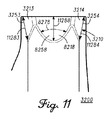
シャフトレシーバ3200のレシーバカプラセット3210に関して、図8及び図11に見られるように、本実施例では、レシーバカプラ8218の弓状面8258は、スリーブカプラ5116の水平曲率半径7176(図7、図10)と相補的である水平曲率半径8278を有し、レシーバカプラ3213の弓状面3253は、スリーブカプラ3111の水平曲率半径7171(図7)と相補的である水平曲率半径8273を有し、レシーバカプラ3214の弓状面3254は、スリーブカプラ3112の水平曲率半径7172(図7)と相補的である水平曲率半径8274を有し、レシーバカプラ8217の弓状面8257は、スリーブカプラ7115の水平曲率半径7175(図7)と相補的である水平曲率半径8277を有する。
With respect to the receiver coupler set 3210 of the
また、本実施例では、レシーバカプラセット3210の弓状面は、スリーブカプラセット3110の弓状面の垂直テーパリングに相補的な垂直テーパリングを有する。例えば、図11に見られるように、レシーバカプラ8218の弓状面8258は、スリーブカプラ5116の垂直テーパリング10186(図10)と相補的な垂直テーパリング11288を有し、レシーバカプラ3213の弓状面3253は、スリーブカプラ3111の垂直テーパリング10181(図10)と相補的な垂直テーパリング11283を有し、レシーバカプラ3214の弓状面3254は、スリーブカプラ3112の垂直テーパリング10182(図10)と相補的な垂直テーパリング11284を有する。図11には示さないものの、レシーバカプラ8217の弓状面8257は、レシーバカプラ8218の垂直テーパリング11288に類似し、スリーブカプラ7115の垂直テーパリングに相補的な垂直テーパリングも有する。
In this embodiment, the arcuate surface of the
本実施形態では、スリーブカプラセット3110の弓状面の垂直テーパリングは実質的に線形であり、図10のスリーブカプラ3111及び3112の垂直テーパリング10181及び10182のプロファイル図において見られるように、実質的に直線で減少する。同様に、図11のレシーバカプラ3213及び3214の垂直テーパリング11283及び11284のプロファイル図において見られるように、レシーバカプラセット3210の弓状面の垂直テーパリングは実質的に線形である。同じ又は他の例では、スリーブカプラセット3110の弓状面及びレシーバカプラセット3210の弓状面の実質的に線形な垂直テーパリングは、実質的に直線となる大きい又は無限の垂直曲率半径を含むものとみなされてもよい。
In this embodiment, the vertical tapering of the arcuate surface of the sleeve coupler set 3110 is substantially linear, as seen in the profile view of the
しかしながら、スリーブカプラ及び/又はレシーバカプラの垂直テーパリングが線形である必要がない他の実施形態であってもよい。図12は、スリーブカプラセット12110を有するシャフトスリーブ12100の一部分の側面図を示す。図13は、レシーバカプラセット13210を有するシャフトレシーバ13200の側部透視断面図を示す。
However, other embodiments where the vertical tapering of the sleeve coupler and / or receiver coupler need not be linear may be possible. FIG. 12 shows a side view of a portion of a
シャフトスリーブ12100はシャフトスリーブ1100(図1〜図7、図10)に類似してもよく、シャフトレシーバ13200はシャフトレシーバ3200(図3〜図4、図8、図10)に類似してもよい。しかしながら、線形ではない垂直テーパリングを有することで、スリーブカプラセット12110はスリーブカプラセット3110と異なる。例えば、スリーブカプラセット12110は、線形であるよりもむしろ湾曲した垂直テーパリング12186、12181及び12182を有し、対応する垂直曲率半径を有してもよい。同様に、レシーバカプラセット13210は、線形であるよりもむしろ湾曲した垂直テーパリング13288、13283及び13284を有し、スリーブカプラセット12110の曲率半径と相補的な対応する垂直曲率半径を有する。したがって、スリーブカプラセット12110のスリーブカプラ及びレシーバカプラセット13120のレシーバカプラは、それぞれこれらの対応する表面積の全体にわたり水平及び垂直に湾曲している。例えば、スリーブカプラ12116の全表面の任意の点に正接する任意の水平線は、スリーブカプラ12116の全表面の任意の他の点に正接しない。同じ又は他の実施形態では、スリーブカプラセット12110の各スリーブカプラの全表面、及びレシーバカプラセット13120の各レシーバカプラの全表面は、それぞれ全体にわたり及び全方向に湾曲している。
The
本開示の異なるスリーブカプラ及びレシーバカプラは、対応する特定の範囲内の曲率を有してもよい。例えば、図7及び図10に関して、スリーブカプラセット3110の水平曲率半径7171、7172、7175及び7176は、それぞれ約0.175インチ(4.45ミリメートル(mm))であるが、約0.1インチ(2.54mm)〜約0.225インチ(5.715mm)の範囲であり得る実施形態があってもよい。図8及び図11に関して、レシーバカプラセット3210の水平曲率半径8273、8274、8277及び8278は水平曲率半径7171、7172、7175及び7176(図7、図10)にそれぞれ相補的に同じ又は類似してもよい。加えて、図12〜図13の実施形態におけるスリーブカプラセット12110及びレシーバカプラセット13210の水平曲率半径は、また、スリーブカプラセット3110及び/又はレシーバカプラセット3210の図1〜図11の実施形態に関して上述したものに類似してもよい。
Different sleeve couplers and receiver couplers of the present disclosure may have curvatures within corresponding specific ranges. For example, with reference to FIGS. 7 and 10, the
前述のように、図1〜図11の実施形態では、スリーブカプラセット3110(図10)及びレシーバカプラセット3210(図11)の垂直テーパリングはほぼ無限大の垂直曲率半径を含むことができ、それにより実質的に直線となる。図12〜図13の実施形態では、スリーブカプラセット12110(図12)及びレシーバカプラセット13210(図13)の垂直テーパリングはより顕著な垂直曲率半径を含む。一例として、スリーブカプラ12116(図12)の垂直テーパリング12186の垂直曲率半径は約0.8インチ(20.32mm)であるが、約0.4インチ(10.16mm)〜2インチ(50.8mm)の範囲であり得る実施形態があってもよい。スリーブカプラセット12110の他の類似の部分の垂直曲率半径も、垂直テーパリング12186について記載した範囲と同じ範囲内であってもよい。加えて、レシーバカプラセット13210(図13)の垂直曲率半径は、スリーブカプラセット12110(図12)について記載した垂直曲率半径と相補的に同じ又は類似であってもよい。
As described above, in the embodiment of FIGS. 1-11, the vertical tapering of sleeve coupler set 3110 (FIG. 10) and receiver coupler set 3210 (FIG. 11) can include a nearly infinite vertical radius of curvature; Thereby, it becomes a substantially straight line. In the embodiment of FIGS. 12-13, the vertical taper of sleeve coupler set 12110 (FIG. 12) and receiver coupler set 13210 (FIG. 13) includes a more pronounced vertical radius of curvature. As an example, the
いくつかの例では、スリーブカプラ及び/又はレシーバカプラの弓状面は、幾何学的構造の部分を含んでもよい。例えば、スリーブカプラ12116の弓状面(図12)は二次曲面を含んでもよく、レシーバカプラ13218の弓状面(図13)は、スリーブカプラ12116の弓状面に相補的な二次曲面を含んでもよい。このような例では、スリーブカプラ12116及びレシーバカプラ13218の二次曲面は、例えば、放物面の一部分又は双曲面の一部分を含んでもよい。その二次弓状面が、錐面の一部分のような縮退二次曲面(degenerate quadric surface)の一部分を含み得るスリーブカプラ及びレシーバカプラを有する例もあってもよい。このような例は、スリーブカプラセット3110及びレシーバカプラセット3200に関する図10〜図11のものに類似してもよい。
In some examples, the arcuate surface of the sleeve coupler and / or receiver coupler may include a portion of the geometric structure. For example, the arcuate surface of sleeve coupler 12116 (FIG. 12) may include a quadric surface, and the arcuate surface of receiver coupler 13218 (FIG. 13) has a quadric surface that is complementary to the arcuate surface of
図10〜図11及び図12〜図13の実施形態では、スリーブカプラセット3110(図10)及び/又は12110(図12)のスリーブカプラの弓状面、並びにレシーバカプラセット3210(図11)及び/又は13210(図13)のレシーバカプラの弓状面は、あらゆる屈曲点がないように、例えば、連続的に湾曲するように構成されてもよい。同じ又は他の実施形態では、このような弓状面はまた、(それらのそれぞれの外周部を除いて)縁なしであるように構成されてもよい。例えば、スリーブカプラ5116(図10)の全表面積は、その外周部内のその全表面積のあらゆる部分に関して縁なしである。加えて、レシーバカプラ8218(図11)の全表面積は、また、その外周部内のその全表面積のあらゆる部分に関して縁なしである。類似の縁なし特性は、また、スリーブカプラ12110(図12)及びレシーバカプラ13218(図13)に共通している。上述の特性により、スリーブカプラがレシーバカプラに対して固定されるとき、接触面積を最大化することができ、その対応するシャフトレシーバに対するそのシャフトスリーブの回転を制限する。 10-11 and 12-13, the sleeve coupler arcuate surface of sleeve coupler set 3110 (FIG. 10) and / or 12110 (FIG. 12), and receiver coupler set 3210 (FIG. 11) and The arcuate surface of the receiver coupler of 13210 (FIG. 13) may be configured to be continuously curved, eg, without any inflection points. In the same or other embodiments, such arcuate surfaces may also be configured to be edgeless (except for their respective perimeters). For example, the total surface area of the sleeve coupler 5116 (FIG. 10) is edgeless with respect to any portion of its total surface area within its outer periphery. In addition, the total surface area of the receiver coupler 8218 (FIG. 11) is also borderless for every part of its total surface area within its outer periphery. Similar borderless characteristics are also common to sleeve coupler 12110 (FIG. 12) and receiver coupler 13218 (FIG. 13). Due to the above characteristics, when the sleeve coupler is fixed with respect to the receiver coupler, the contact area can be maximized, limiting the rotation of the shaft sleeve relative to its corresponding shaft receiver.
図3〜図7及び図10に見られるように、スリーブカプラセット3110はスリーブ外壁3130の上部部分から突出している。同様に、図3〜図4、図8〜図9及び図11に見られるように、レシーバカプラセット3210はレシーバ内壁3230の上部部分内に凹設されている。しかしながら、スリーブカプラセット3110及びレシーバカプラセット3210が別の場所に位置し得る他の実施形態があってもよい。例えば、スリーブカプラセット3110及びレシーバカプラセット3210は、シャフトスリーブ1100及びシャフトレシーバ3200それぞれの下部部分もしくは中間部分に又は下部部分もしくは中間部分の方に位置してもよい。同じ又は他の実施形態では、スリーブカプラセット3110がスリーブ外壁3130内に凹設され、レシーバカプラセット3210がレシーバ内壁3230から突出するように、スリーブカプラセット3110とレシーバカプラセット3210の形状を逆にしてもよい。本明細書中に記載される装置、方法及び製造する物品はこの点に関して限定されない。
As seen in FIGS. 3 to 7 and 10, the sleeve coupler set 3110 protrudes from the upper portion of the sleeve
図3に示される断面図に見られるように、ゴルフカップリング機構1000は、また、シャフトスリーブ1100をシャフトレシーバ3200に固定するように構成された固定用締結具3400を有する。本実施例では、固定用締結具3400は、シャフトレシーバ3200の下部にある通路を介して、シャフトスリーブ1100のスリーブ下端部3192と結合するように構成されたボルトを有する。固定用締結具3400は、ねじ山機構によりスリーブ下端部3192と結合するように構成されている。ねじ山機構が締められるにつれて、固定用締結具3400は、シャフトスリーブ1100をシャフトレシーバ3200の下端部に向かって引くように構成されており、それにより、スリーブカプラセット3110の弓状面をレシーバカプラセット3210の弓状面に対して固定する。
As seen in the cross-sectional view shown in FIG. 3, the
本実施例のような例では、ゴルフクラブヘッド101の本体、シャフトスリーブ1100及び固定用締結具3400の合計総質量は組立後クラブヘッド質量と呼ばれることがある一方、シャフトスリーブ1100及び固定用締結具3400のないゴルフクラブヘッド101の本体の質量は分解後クラブヘッド質量と呼ばれることがある。
In an example such as this embodiment, the total total mass of the body of the
本実施形態では、固定用締結具3400は保持要素3450を有する。保持要素3450は、固定用締結具3400に結合され、固定用締結具3400がシャフトスリーブ1100から分離されたときに、シャフトレシーバ3200から完全に外れるのを制限するか又は少なくとも阻止する。保持要素3450は、シャフトレシーバ3200内に配置され、固定用締結具3400のねじ山の周囲に結合されたワッシャを含む。本実施形態では、例えば、固定用締結具3400を保持要素3450内に押し込むことによって固定用締結具3400のねじ山に沿ったその位置決めを可能にするように、また例えば、固定用締結具3400のねじ山に沿って位置決めされると実質的にその位置にとどまるように、保持要素3450は、固定用締結具3400のねじ山に可撓的に係合するように構成されてもよい。したがって、保持要素3450は、シャフトスリーブ1100がシャフトレシーバ3200から取り外された後、固定用締結具3400の端部をシャフトレシーバ3200内に保持することができ、スリーブ下端部3192への固定用締結具3400の端部の挿入を可能にできる。いくつかの例では、保持要素3450は、固定用締結具3400の材料に比べてより可撓性のある、ナイロン材料又は他のプラスチック材料などの材料を含んでもよい。
In this embodiment, the
他の例では、固定用締結具3400がシャフトレシーバ3200に入る穴は、固定用締結具3400のねじ山に対応するねじ山を含んでもよく、このようなねじ山は、これにより、保持要素として機能してもよい。これらの他の例では、保持要素3450は省略されてもよい。
In other examples, the hole into which the
シャフトスリーブ1110が固定用締結具3400によってシャフトレシーバ3200内に固定されると、スリーブカプラセット3110及びレシーバカプラセット3210はそれら各々の弓状面の少なくとも大部分が互いに対して固定されるように構成されている。例えば、図10〜図11の実施形態では、互いに対して固定されると、スリーブカプラ5116の全表面の少なくとも大部分と、レシーバカプラ8218の全表面の大部分とが互いに接触し、シャフトレシーバ3200に対するシャフトスリーブ1100の回転が制限される。別の例として、図11〜図12の実施形態では、互いに対して固定されると、スリーブカプラ12116の全表面の大部分と、レシーバカプラ13218の全表面の大部分とは、また、互いに接触して回転が制限される。同じ又は他の例では、スリーブカプラセット3110(図10)又は12110(図12)の個々のスリーブカプラと、レシーバカプラセット3210(図11)又は13210(図13)の個々のレシーバカプラとの間の境界面によって画定される接触面積は、個々のレシーバカプラ又は個々のスリーブカプラの全表面の約51%〜約95%であってもよい。いくつかの実施形態では、このような接触面積は、個々のレシーバカプラ及び/又は個々のスリーブカプラの全表面に実質的に近似するか又は等しいなど、更に大きくてもよい。スリーブカプラセット3110(図10)又は12110(図12)のスリーブカプラの弓状面が、レシーバカプラセット3200(図11)又は13210(図13)のレシーバカプラの弓状面に対して固定されると、各々の接触面積にわたり垂直抗力が互いに作用する例もあってもよい。
When shaft sleeve 1110 is secured within
本実施例では、固定用締結具3400がシャフトレシーバ3200内のシャフトスリーブ1100を固定しているとき、スリーブトップ部3170はシャフトレシーバ3200の外部にとどまり、レシーバカプラセット3210に対するスリーブカプラセット3110の固定により、スリーブトップ部3170の下端部3171はシャフトレシーバ3200の上端部から離間している。このような内蔵空間により製造公差が緩和され、スリーブカプラセット3110をレシーバカプラセット3210に対して適切に固定できることを確実とする。
In this embodiment, when the fixing
同じ又は他の例では、スリーブカプラセット3110の1つ以上のスリーブカプラの一部分は、シャフトレシーバ3200の上端部を越えて突出してもよい。スリーブカプラセット3110の1つ以上のスリーブカプラが、レシーバカプラセット3210の1つ以上のレシーバカプラの下端部を越えて延出し得る例があってもよい。他の例では、レシーバカプラセットの1つ以上のレシーバカプラは、スリーブカプラセット3110の1つ以上のスリーブカプラの下端部を越えて延出してもよい。上述した特徴のいくつかは、要求される製造公差を緩和するためにゴルフカップリング機構1000へと設計されてもよい一方、レシーバカプラセット3210に対するスリーブカプラセット3110の適切な固定をなお可能にしてもよい。
In the same or other examples, a portion of one or more sleeve couplers of the sleeve coupler set 3110 may protrude beyond the upper end of the
図14は、図4の線XIV−XIVにおいて見た、構成1400のゴルフカップリング機構1000の上部断面図を示す。ゴルフカップリング機構1000は、図3〜図4及び図14では構成1400において示され、スリーブカプラセット3110のスリーブカプラ3111、7115、3112及び5116(図7)は、それぞれレシーバカプラセット3210のレシーバカプラ3213、8217、3214及び8218(図8)に結合されている。上記のように、シャフト穴軸6150(図6)はシャフトスリーブ1100のスリーブ軸5150と非同軸であるため、図14の構成1400は、シャフト穴軸6150(図6)とシャフトレシーバ3200(図3〜図4、図8〜図9)との間に及び/又はシャフト102(図1)とゴルフクラブヘッド101(図1)との間に第1のライ角及び第1のロフト角を有することができる。
FIG. 14 shows a top cross-sectional view of the
図15は、図4の線XIV−XIVにおいて見た、構成1500のゴルフカップリング機構1000の上部断面図を示す。構成1500では、スリーブカプラセット3110のスリーブカプラ3112、5116、3111及び7115(図7)は、それぞれレシーバカプラセット3210のレシーバカプラ3213、8217、3214及び8218(図8)に結合されている。上記のように、シャフト穴軸6150(図6)はシャフトスリーブ1100のスリーブ軸5150と非同軸であるため、図15の構成1500は、シャフト穴軸6150(図6)とシャフトレシーバ3200(図3〜図4、図8〜図9)との間に及び/又はシャフト102(図1)とゴルフクラブヘッド101(図1)との間に第2のライ角及び第2のロフト角を有することができる。
FIG. 15 shows a top cross-sectional view of the
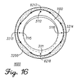
図16は、図4の線XIV−XIVにおいて見た、構成1600のゴルフカップリング機構1000の上部断面図を示す。構成1600では、スリーブカプラセット3110のスリーブカプラ7115、3112、5116及び3111(図7)は、それぞれレシーバカプラセット3210のレシーバカプラ3213、8217、3214及び8218(図8)に結合されている。上記のように、シャフト穴軸6150(図6)はシャフトスリーブ1100のスリーブ軸5150と非同軸であるため、図16の構成1600は、シャフト穴軸6150(図6)とシャフトレシーバ3200(図3〜図4、図8〜図9)との間に及び/又はシャフト102(図1)とゴルフクラブヘッド101(図1)との間に第3のライ角及び第3のロフト角を含む。
FIG. 16 shows a top cross-sectional view of the
図17は、図4の線XIV−XIVにおいて見た、構成1700のゴルフカップリング機構1000の上部断面図を示す。構成1700では、スリーブカプラセット3110のスリーブカプラ5116、3111、7115及び3112(図7)は、それぞれレシーバカプラセット3210のレシーバカプラ3213、8217、3214及び8218(図8)に結合されている。上記のように、シャフト穴軸6150(図6)はシャフトスリーブ1100のスリーブ軸5150と非同軸であるため、図17の構成1700は、シャフト穴軸6150(図6)とシャフトレシーバ3200(図3〜図4、図8〜図9)との間に及び/又はシャフト102(図1)とゴルフクラブヘッド101(図1)との間に第4のライ角及び第4のロフト角を含む。
FIG. 17 shows a top cross-sectional view of the
スリーブ軸5150及びスリーブカプラセット3110に対するシャフト穴軸6150の角度に応じて、図14〜図17に示される構成により異なるライ角及びロフト角アライメントを得てもよい。例えば、本実施形態では、図6に見られるように、シャフト102(図1)がシャフトスリーブ1100に挿入されたときにスリーブカプラ3112の方に傾くように、シャフト穴軸6150とスリーブ軸5150との間の角度により、シャフト穴3120の下部をスリーブカプラ3111の方に向ける。
Depending on the angle of the
したがって、構成1400(図14)では、第1のライ角はより小さいライ角を有してもよく、第1のロフト角は中立又は中間のロフト角を有してもよい。一例として、第1のライ角は、シャフト102のグリップ端部をゴルフクラブヘッド101(図1)のヒール部の方に約0.2度〜約4度傾けるように設定することができ、これにより、構成1400におけるゴルフクラブのライ角は減少する。本実施例の中立である第1のロフト角は、構成1400においてシャフト102の傾きに影響しない。
Thus, in configuration 1400 (FIG. 14), the first lie angle may have a smaller lie angle and the first loft angle may have a neutral or intermediate loft angle. As an example, the first lie angle can be set so that the grip end of the
構成1500(図15)では、第2のライ角はより大きいライ角を有してもよく、第2のロフト角は中立又は中間のロフト角を有してもよく、このロフト角は構成1400(図14)の第1のロフト角と類似していても等しくてもよい。一例として、第2のライ角は、シャフト102のグリップ端部をゴルフクラブヘッド101(図1)のトウ部の方に約0.2度〜約4度傾けるように設定することができ、これにより、構成1500におけるゴルフクラブのライ角は増大する。本実施例の中立である第2のロフト角は、構成1500においてシャフト102の傾きに影響しない。
In configuration 1500 (FIG. 15), the second lie angle may have a larger lie angle, and the second loft angle may have a neutral or intermediate loft angle, the loft angle being the
構成1600(図16)では、第3のロフト角はより小さいロフト角を有してもよく、第3のライ角は中立又は中間のライ角を有してもよい。一例として、第3のロフト角は、シャフト102のグリップ端部をゴルフクラブヘッド101(図1)のリア部の方に約0.2度〜約4度傾けるように設定することができ、これにより、構成1600におけるゴルフクラブのロフト角は減少する。本実施例の中立である第3のライ角は、構成1600においてシャフト102の傾きに影響しない。
In configuration 1600 (FIG. 16), the third loft angle may have a smaller loft angle, and the third lie angle may have a neutral or intermediate lie angle. As an example, the third loft angle can be set so that the grip end of the
構成1700(図17)では、第4のロフト角はより大きいロフト角を有してもよく、第4のライ角は中立又は中間のライ角を有してもよく、このライ角は構成1600(図16)の第3のライ角と類似していても等しくてもよい。一例として、第4のロフト角は、シャフト102のグリップ端部をゴルフクラブヘッド101(図1)のフロント部又は打面の方に約0.2度〜約4度傾けるように設定することができ、これにより、構成1700におけるゴルフクラブのロフト角は増大する。本実施例の中立である第4のライ角は、構成1700におけるシャフト102の傾きに影響しない。
In configuration 1700 (FIG. 17), the fourth loft angle may have a larger loft angle, the fourth lie angle may have a neutral or intermediate lie angle, and this lie angle is the
他の実施形態では、シャフトスリーブ1100のスリーブ軸5150(図6)に対するシャフト穴軸6150(図6)の角度及び/又は向きを変えることによって、他のライ角とロフト角との関係を構成してもよい。更に、図14〜図17から分かるように、スリーブカプラ3111、3112、5116及び7115は互いに対称であり、レシーバカプラ3213、3214、8217及び8218も互いに対称である。異なる実施形態では、(4つではなく)2つのみの異なるライ角とロフト角との組み合わせが可能となるように、スリーブカプラ及びレシーバカプラのうちの対向するもののみが互いに対称であってもよい。
In other embodiments, changing the angle and / or orientation of the shaft bore axis 6150 (FIG. 6) with respect to the sleeve axis 5150 (FIG. 6) of the
図1〜図17のゴルフカプラ機構に関する上述した様々な特徴は、調節可能なシャフトカップリング機構を有する他のゴルフクラブヘッドと比較した場合、ゴルフカプラ機構が使用されるゴルフクラブに対していくつかの性能利点を付与することもできる。例えば、必要な部品の数が少ないことから及び/又はレシーバカプラセット3210がシャフトレシーバ3200(図3)の上端部の方のみに配置されることから、ホーゼル1015(図1)のホーゼル直径1031を最小に維持することができ、及び/又は対応する標準的なゴルフクラブヘッドのホーゼル直径と比較的変わらないものとすることができる。いくつかの例では、図8に見られるように、ホーゼル直径1031はレシーバ上端部1032において、約20mm未満、例えば、約0.55インチ(約14mm)、又は例えば、約0.53インチ(約13.46mm)であってもよい。加えて、シャフトレシーバ3200のレシーバ上端部1032において示されるように、シャフトレシーバ3200の上部壁厚さ9250(図8〜図9)を最小にすることができる。例えば、上部壁厚さ9250は、約0.035インチ(約0.9mm)以下、また例えば、約0.024インチ(約0.61mm)であってもよい。
The various features described above with respect to the golf coupler mechanism of FIGS. 1-17 are several in comparison to golf clubs in which the golf coupler mechanism is used when compared to other golf club heads having adjustable shaft coupling mechanisms. The performance advantage can also be imparted. For example, the
図8に見られるように、本実施形態では、上部壁厚さ9250は、レシーバ上端部1032に沿って厚みが変化し、レシーバ上端部1032に、少なくとも1つのホーゼル上壁薄肉部分8252と、少なくとも1つのホーゼル上壁厚肉部分8251とを有する。ホーゼル直径1031の中心点に対して径方向に測定した場合、レシーバ上端部1032におけるホーゼル上壁厚肉部分8251は、約2.3mm以下の厚みを有することができる。ホーゼル直径1031の中心点に対して径方向に測定した場合、レシーバ上端部1032におけるホーゼル上壁薄肉部分8252は、約0.9mm以下の厚みを有することができる。本実施例では、ホーゼル直径1031の中心点に対して径方向に測定した場合、ホーゼル上壁厚肉部分8251は約1.27mm以下、ホーゼル頂壁薄肉部分8252は0.64mm以下であってもよい。
As can be seen in FIG. 8, in this embodiment, the
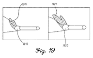
上述のように、ホーゼル直径1031を最小にすることにより、ホーゼル1015の空気力学的抗力が低下することで、ゴルフクラブヘッド101の空気力学的特性を向上させることができる。図19は、ゴルフクラブヘッド1910及び1920の各ホーゼルの停滞抗力伴流領域1911及び1921の比較を示す。ゴルフクラブヘッド1910は約0.5インチのホーゼル直径を有し、ゴルフクラブヘッド1920は約0.62インチのより大きいホーゼル直径を有する。いくつかの例では、ゴルフクラブヘッド1910はゴルフクラブヘッド101(図1〜図4、図8〜図9)に類似してもよい。図19に見られるように、クラブヘッド1920のより大きいホーゼル直径によってそのホーゼルの下流側により大きい停滞抗力伴流領域1921が生成され、クラブヘッド1910のより小さい停滞抗力伴流領域1911と比較した場合に空気力学的抗力の値が高くなる。図20は、ゴルフクラブヘッド1910及び1920のホーゼル直径に関するオープンフェース角の関数としての抗力のチャートを示す。いくつかの例では、クラブヘッド1910は、また、約0.335インチ(約8.5mm)のシャフト厚さなど、低減されたシャフト厚さを有するゴルフクラブシャフトを含んでもよい。同じ又は他の例では、50度以下のオープンフェースの向きでは、このようなホーゼル直径の差により、ゴルフクラブヘッド1920のより大きい抗力と比較した場合、ゴルフクラブヘッド1910のドラグ抵抗(drag resistance)が約0.1ポンド以下低くなってもよい。同じ又は他の例では、ゴルフクラブヘッド1910の抗力は、ほぼスクエアの向きにおける約1.2ポンドから、約50度のオープンフェースの向きにおける約0.2ポンドまでの範囲であってもよい。
As described above, the aerodynamic characteristics of the
同じ又は他の実施形態では、調節可能なシャフトカップリング機構を有する他のゴルフクラブヘッドと比較した場合、図1〜図17のゴルフカプラ機構の質量及び/又は質量比をそれら各々のゴルフクラブヘッドに対して最小にしてもよい。例えば、ゴルフクラブヘッド101(図1〜図4、図8〜図9)がドライバー型ゴルフクラブヘッドを有する例では、クラブヘッド101の種々の要素は、以下の表1に示すものに類似する質量特性を有してもよい。
In the same or other embodiments, the mass and / or mass ratio of the golf coupler mechanism of FIGS. 1-17 can be compared to their respective golf club heads when compared to other golf club heads having adjustable shaft coupling mechanisms. May be minimized. For example, in an example where the golf club head 101 (FIGS. 1-4, 8-9) has a driver-type golf club head, the various elements of the

このような例では、以下の表2に示すように、組立後のクラブヘッド101に対するゴルフカプラ機構1000の質量の比は非常に低くなってもよい。
In such an example, as shown in Table 2 below, the ratio of the mass of the
例えば、ゴルフクラブヘッド101(図1〜図4、図8〜図9)がフェアウェイウッド型ゴルフクラブヘッドを有する他の例では、クラブヘッド101の種々の要素は、以下の表3に示すものに類似する質量特性を有してもよい。
For example, in another example where the golf club head 101 (FIGS. 1-4, 8-9) has a fairway wood type golf club head, the various elements of the
このような例では、以下の表4に示すように、組立後のクラブヘッド101に対するゴルフカプラ機構1000の質量の比は非常に低くなってもよい。
In such an example, as shown in Table 4 below, the ratio of the mass of the
上述の質量、寸法及び/又は位置特性により、ゴルフクラブヘッドの質量分布及び/又は重心(CG)の位置に関する利点及び/又は柔軟性を提供することができる例があってもよい。例えば、シャフトスリーブ1100のシャフトスリーブ重心1150(図1)は、シャフトスリーブCG垂直距離1159(図1)に配置されるように構成されてもよい。
There may be examples where the above-described mass, size and / or position characteristics can provide advantages and / or flexibility with respect to the mass distribution and / or the location of the center of gravity (CG) of the golf club head. For example, the shaft sleeve center of gravity 1150 (FIG. 1) of the
クラブヘッド101(図1〜図4、図8〜図9)がドライバー型ゴルフクラブヘッドを有する実施形態のようないくつかの例では、シャフトスリーブ1100のシャフトスリーブ重心1150(図1)は、ドライバー型クラブヘッド101のソール1014の外部ソール下端部10141の上方約50mm未満のシャフトスリーブCG垂直距離1159に配置されるように構成されてもよい。同じ又は他の例では、シャフトスリーブCG垂直距離1159は、外部ソール下端部10141の上方約46.2mm未満でありってもよい。同じ又は他の例では、シャフトスリーブCG垂直距離1159は、外部ソール下端部10141の上方約43.7mm未満であってもよい。シャフトスリーブ1100のシャフトスリーブ重心1150は、また、いくつかの実施形態では、ドライバー型の組立後のゴルフクラブヘッド101の組立後のクラブヘッド重心1050(図1)の上方約0.59インチ(約15mm)未満のシャフトスリーブCG垂直距離1059(図1)に配置されるように構成されてもよい。同じ又は他の実施形態では、シャフトスリーブCG垂直距離1159は、ドライバー型クラブヘッド101の組立後のクラブヘッドCG垂直距離1058よりも少なくとも約7.6mm大きくされてもよい。
In some examples, such as embodiments where the club head 101 (FIGS. 1-4, 8-9) has a driver-type golf club head, the shaft sleeve center of gravity 1150 (FIG. 1) of the
クラブヘッド101(図1〜図4、図8〜図9)がフェアウェイウッド型ゴルフクラブヘッドを有する実施形態のような他の例では、シャフトスリーブ1100のシャフトスリーブ重心1150(図1)は、フェアウェイウッド型クラブヘッド101のソール1014の外部ソール下端部の上方約35.6mm未満のシャフトスリーブCG垂直距離1159に配置されるように構成されてもよい。同じ又は他の例では、シャフトスリーブCG垂直距離1159は、フェアウェイウッド型クラブヘッド101のソール1014の外部ソール下端部10141の上方約1.35インチ(約34.3mm)未満であってもよい。シャフトスリーブ1100のシャフトスリーブ重心1150は、また、いくつかの実施形態では、フェアウェイウッド型の組立後のゴルフクラブヘッド101の組立後のクラブヘッド重心1050(図1)の上方約19mm未満のシャフトスリーブCG垂直距離1059(図1)に配置されるように構成されてもよい。同じ又は他の実施形態では、シャフトスリーブCG垂直距離1159は、フェアウェイウッド型クラブヘッド101の組立後のクラブヘッドCG垂直距離1058よりも少なくとも約16.5mm大きくされてもよい。
In other examples, such as embodiments where the club head 101 (FIGS. 1-4, 8-9) has a fairway wood type golf club head, the shaft sleeve center of gravity 1150 (FIG. 1) of the
本実施例では、図1に見られるように、ホーゼル1015は、ホーゼル1015の長手方向中心線に沿って延びるホーゼル軸1016を有する。ホーゼル軸1016は、下部水平軸1019に対してホーゼルライ角1018を画定する。下部水平軸1019は、ソール下端部10141に水平に正接する。いくつかの実施形態では、ホーゼルライ角1018は、例えば、約58度であってもよい。本実施形態では、シャフトスリーブCG垂直距離1159及び組立後のクラブヘッドCG垂直距離1058は、下部水平軸1019から垂直に延びる。
In this example, as seen in FIG. 1, the
クラブヘッド101は、また、クラウン1017の上端部に垂直に、ソール下端部10141に対して延びるクラウン高さ垂直距離1018を有する。例えば、クラブヘッド101がドライバー型ゴルフクラブヘッドを有するいくつかの実施形態では、クラウン高さ垂直距離1018はソール下端部10141に対して少なくとも約59.7mmであってもよい。同じ又は他の実施形態では、組立後のクラブヘッドCG垂直距離は、ソール下端部10141に対して約33mm未満であってもよい。
図1に見られるように、レシーバ上端部1032がホーゼル1015の上部にあり、ゴルフクラブヘッド101のクラウン1017の上端部よりも下にとどまるように構成されている例もあってもよい。同じ又は他の実施形態では、ホーゼル1015には円筒状外部上部部分がない場合があり、クラウン1017は、ホーゼル1015の円筒状外部形状を画定することなく、ホーゼル1015のレシーバ上端部1032において実質的に円形の外周部へと移行してもよい。このような特徴により、シャフトスリーブ1100の重心の位置を組立後のゴルフクラブヘッド101の重心に近づけることを可能にすることができる。
As seen in FIG. 1, there may be an example in which the receiver
図に戻ると、図18は、本開示による、ゴルフカプラ機構を提供し、形成し、及び/又は製造するために使用されてもよい方法18000のフローチャートを示す。いくつかの例では、ゴルフカプラ機構は、図1〜図11及び図14〜図16のゴルフカプラ機構1000又は図12〜図13のゴルフカプラ機構に類似してもよい。
Returning to the drawings, FIG. 18 shows a flowchart of a
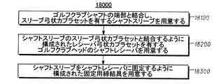
方法18000は、ゴルフクラブシャフトの端部と結合し、スリーブ弓状カプラセットを含むシャフトスリーブを用意するためのブロック18100を有する。いくつかの例では、シャフトスリーブはシャフトスリーブ1100(図1〜図7、図10、図14〜図16)及び/又はシャフトスリーブ12100(図12)に類似してもよい。ゴルフクラブシャフトは、ゴルフクラブシャフト102(図1、図5)に類似してもよい。同じ又は他の例では、スリーブ弓状カプラセットは、スリーブカプラセット3110(図3〜図7、図10、図14〜図17)及び/又はスリーブカプラセット12110(図12)に類似してもよい。
The
方法18000のブロック18200は、シャフトスリーブのスリーブ弓状カプラセットと結合するように構成されたレシーバ弓状カプラセットを有するゴルフクラブヘッドのシャフトレシーバを用意することを有する。いくつかの例では、シャフトレシーバは、シャフトレシーバ3200(図3〜図4、図8〜図9、図11、図14〜図17)及び/又はシャフトレシーバ13200(図13)に類似してもよい。レシーバ弓状カプラセットは、レシーバカプラセット3210(図3〜図4、図8〜図9、図11、図14〜図17)及び/又はレシーバカプラセット13210(図13)に類似してもよい。
方法18000のブロック18300は、シャフトスリーブをシャフトレシーバに固定するように構成された固定用締結具を用意することを有する。いくつかの例では、固定用締結具は、固定用締結具3400(図3〜図4)に類似してもよい。固定用締結具は、シャフトスリーブをシャフトレシーバの方に引き、スリーブ弓状カプラセットをレシーバ弓状カプラセットに対して固定させるように構成されてもよい。
いくつかの例では、方法18000の異なるブロックの1つ以上は、単一のブロックに組み合わても、同時に実施してもよく、及び/又はこのようなブロックの順序を変更してもよい。例えば、いくつかの実施形態では、必要に応じて、ブロック18200とブロック18300とを組み合わせてもよい。同じ又は他の例では、方法18000のブロックのいくつかを、いくつかのサブブロックに細分してもよい。一例として、ブロック18100は、スリーブ弓状カプラセットのスリーブカプラの弓状面の水平曲率半径を形成するためのサブブロックと、スリーブ弓状カプラセットのスリーブカプラの弓状面の垂直テーパリングを形成するためのサブブロックとを有してもよい。方法18000が更なる又は異なるブロックを有し得る例があってもよい。一例として、方法18000は、ブロック18200のシャフトレシーバ用のゴルフクラブヘッドを用意するための別のブロック、及び/又はブロック18100のシャフトスリーブ用のシャフトを用意するための別のブロックを有してもよい。加えて、方法18000が上述のステップの一部のみを有し得る例があってもよい。例えば、いくつかの実施においてブロック18300は任意であってもよい。本開示の範囲から逸脱することなく方法18000の他の変化形態を実施してもよい。
In some examples, one or more of the different blocks of
スロットキャップゴルフカップリング機構
先の図を参照すると、図21は、一実施形態による、ゴルフカップリング機構211000を有するゴルフクラブヘッド21101の前部斜視図を示す。多くの実施形態では、ゴルフカップリング機構211000は、ゴルフクラブシャフト21102などのゴルフクラブシャフトの端部に結合されるように構成されたシャフトスリーブ211100を有してもよい。種々の実施形態では、ゴルフクラブヘッド21101はゴルフクラブヘッド101(図1)に類似してもよく、ゴルフカップリング機構211000はゴルフカップリング機構1000(図1)に類似してもよく、及び/又はゴルフクラブシャフト21102はゴルフクラブシャフト102(図1)に類似するかもしくは同一であってもよい。したがって、ゴルフカップリング機構211000は、シャフトスリーブ211100及びシャフトレシーバ213200を有してもよい。一方、シャフトスリーブ211100はシャフトスリーブ1100(図1)に類似してもよく、及び/又はシャフトレシーバ213200はシャフトレシーバ3200(図3)に類似してもよい。
Slot Cap Golf Coupling Mechanism Referring to the previous figure, FIG. 21 shows a front perspective view of a
再び先の図面を参照すると、図22は、図21の実施形態による、ゴルフクラブヘッド21101(図21)から分離されたシャフトスリーブ211100の側面図を示す。一方、図23は、図21の実施形態による、図22の線XXIII−XXIIIに沿ったシャフトスリーブ211100の断面図を示す。
Referring again to the previous drawing, FIG. 22 shows a side view of the
図22を参照すると、シャフトスリーブ211100は、シャフトスリーブ本体22103及びシャフトスリーブキャップ22104を有する。更に、多くの実施形態では、シャフトスリーブ本体22103は、スリーブ本体外壁223130から突出している1つ以上のカプラを有するスリーブカプラセット223110を有することができ、シャフトレシーバ213200(図21)は、シャフトスリーブ211100のスリーブカプラセット223110に係合し、シャフトレシーバ213200に対するシャフトスリーブ211100の回転を制限するように構成されたレシーバカプラセットを有してもよい。これら又は他の実施形態では、スリーブカプラセット213110はスリーブカプラセット3110(図3)に類似してもよく、スリーブ本体外壁223130はスリーブ外壁3130(図3)に類似してもよく、及び/又はレシーバカプラセットはレシーバカプラセット3210(図3)に類似してもよい。以下で更に詳細に説明するように、多くの実施形態では、シャフトスリーブキャップ22104はフェルールを有してもよく、シャフトスリーブ本体22103をゴルフクラブシャフト21102(図21)と結合するように動作可能であってもよい。
Referring to FIG. 22, the
一方、ここで図23を参照すると、シャフトスリーブ211100は、(i)ゴルフクラブシャフト21102(図21)の端部を受け入れるように構成されたシャフト穴233120、(ii)スリーブ本体下端部233192にある固定用締結具穴23105、(iii)穴底面23111、及び/又は(iv)シャフトスリーブ上端部231191を有してもよい。シャフトスリーブ211100をシャフトレシーバ213200(図21)に固定するために、固定用締結具穴23105は、固定用締結具(図示せず)を受け入れるように構成されてもよい。更に、穴底面23111は、シャフト穴232120の底面(例えば、最深面)を有してもよい。多くの実施形態では、シャフト穴233120はシャフト穴3120(図3)に類似してもよく、固定用締結具穴23105は固定用締結具3400(図3)を受け入れるように構成された穴と類似するかもしくは同一であってもよく、スリーブ本体下端部233192はスリーブ下端部3192(図3)と類似するるかもしくは同一であってもよく、固定用締結具は固定用締結具3400(図3)と類似するかもしくは同一であってもよく、及び/又はシャフトスリーブ上端部231191はスリーブ上端部1191(図3)と類似するかもしくは同一であってもよい。
On the other hand, referring now to FIG. 23, the
更に、シャフトスリーブ本体22103がシャフトスリーブキャップ22104に結合される場合、シャフトスリーブ211100は、シャフトスリーブ高さ23119と、シャフトスリーブ本体高さ23120と、シャフトスリーブキャップ高さ23121と、シャフトスリーブキャップ上部高さ23122とを有してもよい。シャフトスリーブ高さ23119は、スリーブ本体下端部233192にほぼ垂直に測定した、スリーブ本体下端部233192からシャフトスリーブ上端部231191までの距離を意味してもよい。一方、シャフトスリーブ本体高さ23120は、シャフトスリーブ高さ23119に平行に測定した、スリーブ本体下端部233192からシャフトスリーブ本体22103の上端部までの距離を意味してもよい。シャフトスリーブキャップ高さ23121は、シャフトスリーブ高さ23119に平行に測定した、シャフトスリーブキャップ22104の下部からシャフトスリーブ上端部231191までの距離を意味してもよい。更に、シャフトスリーブキャップ上部高さ23122は、シャフトスリーブ高さ23119とシャフトスリーブ本体高さ23120との間の差を意味してもよい。
Further, when the
例えば、シャフトスリーブ高さ23119は約1.78インチ以上、約1.82インチ以下であってもよい。特定の例では、シャフトスリーブ高さ23119は約1.8インチであってもよい。
For example, the
更に、シャフトスリーブ本体高さ23120は約1.527インチ以上、約1.567インチ以下であってもよい。特定の例では、シャフトスリーブ本体高さ23120は約1.547インチであってもよい。
Further, the shaft
更にまた、シャフトスリーブキャップ高さ23121は約0.43インチ、且つ約0.47インチ以下であってもよい。特定の例では、シャフトスリーブキャップ高さ23121は約0.45インチであってもよい。
Furthermore, the shaft
一方、例えば、シャフトスリーブキャップ上部高さ23122は約0.23インチ以上、約0.27インチ以下であってもよい。特定の例では、シャフトスリーブ本体高さ23122は約0.25インチであってもよい。
On the other hand, for example, the shaft sleeve cap
いくつかの実施形態では,固定用締結具穴23105に挿入するための固定用締結具(図示せず)はチタン被覆鋼を有してもよい。更に、固定用締結具は固定用締結具質量を有してもよい。固定用締結具質量は約2.7グラム以上であってもよい。
In some embodiments, a fastening fastener (not shown) for insertion into the
次の図面を参照すると、図24は、図21の実施形態による、シャフトスリーブキャップ22104(図22)から分離されたシャフトスリーブ本体22103の側面図を示す。シャフトスリーブ本体22103は、1つ以上の領域24106に関連してもよい。例えば、領域24106は、締結具領域24107と、中間領域24108と、カプラ領域24109と、キャップインターフェース領域24110とを有してもよい。
Referring to the following drawings, FIG. 24 shows a side view of the
締結具領域24107は、スリーブ本体下端部233192と穴底面23111(図23)との間に位置するシャフトスリーブ本体22103の一部分を意味してもよい。一方、カプラ領域24109は、スリーブカプラセット223110の最下点(例えば、スリーブ本体下端部233192(図23)に最も近いスリーブカプラセット223110の点)から、スリーブカプラセット223110の最高点(例えば、スリーブ本体下端部233192から最も遠いスリーブカプラセット223110の点)まで位置するシャフトスリーブ本体の一部分を意味してもよい。一方、中間領域24108は、締結具領域24107とカプラ領域24109との間のシャフトスリーブ本体22103の一部分を意味してもよい。キャップインターフェース領域24110は、中間領域24108に対してカプラ領域24109の反対側にあるシャフトスリーブ本体22103の一部分を意味してもよい。
The
ゴルフクラブヘッド21101(図21)がスイングされたとき及び/又はゴルフボールを打つように操作されたとき、締結具領域24107及びカプラ領域24109は高い応力を受ける可能性がある。一方、中間領域24108及び/又はキャップインターフェース領域24110は、締結具領域24107及びカプラ領域24109が受ける高い応力よりも低い応力を受ける可能性がある。
When the golf club head 21101 (FIG. 21) is swung and / or manipulated to strike a golf ball, the
固定用締結具によってシャフトスリーブ211100(図21)をシャフトレシーバ213200(図21)に固定することで、締結具領域24107における高い応力の相殺を補助することができる。更に、カプラ領域24109において受ける可能性のある高い応力のため、スリーブカプラセット223110のカプラは、シャフトスリーブ本体22103のスリーブ本体壁に付加的な厚みを付与するように構成されたソリッドローブ(solid lobe)を有してもよい。したがって、カプラはスリーブ本体壁をカプラ領域24109において強化し、カプラ領域24109におけるこれらの高い応力を相殺することができる。スリーブカプラセット223110のカプラは(例えば、直線的に又は曲線的に)勾配することができ、スリーブ本体下端部233192から最も遠いカプラ領域24109の端部(例えば、カプラ領域24109がキャップインターフェース領域24110に接続する位置)に最大厚さを有し、スリーブ本体下端部233192(図23)に最も近いカプラ領域24109の端部(例えば、カプラ領域24109が中間領域24108と接続する位置)に最小厚さを有する。例えば、最大厚さは約0.75インチの厚さであってもよい。最小厚さは約0.020インチの厚さであってもよい。多くの実施形態では、スリーブカプラセット223110(図22)のカプラを勾配させることで、中間領域24108とキャップインターフェース領域24110との間に連続性(例えば、厚みの滑らかな移行)を付与することができる。
By fixing the shaft sleeve 211100 (FIG. 21) to the shaft receiver 213200 (FIG. 21) with a fixing fastener, high stress cancellation in the
いくつかの実施形態では、スリーブカプラセット223110のカプラは輪郭が対称であってもよい。スリーブカプラセット223110のカプラの長さは約0.38インチ以下であってもよく(例えば、シャフトスリーブ本体42103のスリーブ本体外壁223130の一部)、約0.26インチ以上であってもよい(例えば、シャフトスリーブ本体22103のスリーブ本体外壁223130の別の部分)。
In some embodiments, the couplers of the sleeve coupler set 223110 may be symmetric in contour. The coupler length of the sleeve coupler set 223110 may be about 0.38 inches or less (eg, a portion of the sleeve body
いくつかの実施形態では、カプラは、シャフトスリーブ本体22103のスリーブ本体外壁223130の第1部分の方が別の部分(例えば、第1部分に正対するか又は180度対向する部分)よりも長くなるように、スリーブカプラセット223110のカプラは輪郭が非対称であってもよい。スリーブカプラセット223110のカプラの長さは約0.38インチ以下であってもよく(例えば、シャフトスリーブ本体22103のスリーブ本体外壁223130の部分)、約0.260インチ以上であってもよい(例えば、シャフトスリーブ本体22103のスリーブ本体外壁223130の別の部分)。多くの実施形態では、スリーブカプラセット223110(図22)のカプラは、スリーブ本体下端部233192から最も遠いカプラ領域24109の端部(例えば、カプラ領域24109がキャップインターフェース領域24110と接続する位置)における、シャフトスリーブ本体22103のスリーブ軸に最も近いシャフトスリーブ本体22103のスリーブ本体外壁223130の部分において最長であってもよい。スリーブ軸はスリーブ軸5150(図5)と類似するかもしくは同一であってもよい。換言すると、スリーブカプラセット223110(図22)のカプラは、スリーブ軸を有し、スリーブ本体下端部233192にほぼ垂直に延びる面に交差するシャフトスリーブ本体22103のスリーブ本体外壁223130の部分において最長であってもよい。
In some embodiments, the coupler is such that the first portion of the sleeve body
一方、ゴルフクラブヘッド21101がスイングされたとき及び/又はゴルフボールを打つように操作されたとき、中間領域24108が受ける応力はより低くなることから、シャフトスリーブ本体のスリーブ本体壁はカプラ領域24109の一部もしくは全体よりも中間領域24108においてより薄くされてもよいく、及び/又は中間領域24108は穴もしくは凹部を有することにより重量を低減してもよい。例えば、中間領域24108におけるシャフトスリーブ本体22103のスリーブ本体壁は約0.020インチの厚さ(例えば、平均厚さ)を有してもよい。
On the other hand, when the
ここで図23に戻ると、いくつかの実施形態では、シャフト穴233120は、約0.346インチの幅(例えば、直径)を有してもよい。これらの実施形態では、幅は平均幅を有してもよく、及び/又はシャフト穴233120の全体にわたりほぼ一定であってもよい。
Returning now to FIG. 23, in some embodiments, the
種々の実施形態では、シャフトスリーブ本体22103はシャフト穴233120にエッチングチャネル23112を有し、ゴルフクラブシャフト21102(図21)をシャフトスリーブ本体22103にエポキシ接着するためのより適切な表面積を付与することができる。エッチングチャネル23112はカプラ領域24109(図24)に、及び/又は例えばカプラ領域24109(図24)に近い方の中間領域24108(図24)の半分など、中間領域24108(図24)の一部もしくは全体に配置されてもよい。
In various embodiments, the
これら又は他の実施形態では、シャフトスリーブ本体22103は受け入れ溝23113(例えば、アンダカットノッチ)を有してもよい。以下で更に詳細に説明するように、受け入れ溝23113は、シャフトスリーブキャップ22104の突出部25114(図25)と連通して相互係止し、シャフトスリーブキャップ22104をシャフトスリーブ本体22103に固定することができる。したがって、多くの実施形態では、受け入れ溝23113は、突出部25114(図25)を補完することができる。いくつかの実施形態では、受け入れ溝23113は、キャップインターフェース領域24110(図24)に配置されてもよい。多くの実施形態では、受け入れ溝23113は、キャップインターフェース領域24110(図24)とカプラ領域24109(図24)との境界面に配置されてもよい。
In these or other embodiments, the
ここで先の図面を参照すると、図25は、図21の実施形態による、シャフトスリーブ本体22103(図22)から分離されたシャフトスリーブキャップ22104の側面図を示す。
Referring now to the previous drawings, FIG. 25 shows a side view of the
いくつかの実施形態では、シャフトスリーブキャップ22104は、キャップ壁25115を有してもよい。更に、キャップ壁22115は、突出部25114と1つ以上のスリット25116とを有してもよい。
In some embodiments, the
突出部25114は、例えば、キャップ壁25115の端部など、キャップ壁25115から延出するリップを有してもよい。したがって、突出部25114は、キャップ壁25115の残部及び/又はシャフト穴233120の幅(例えば、直径)よりも大きい幅(例えば、直径)を有してもよい。
The
一方、スリット25116は、シャフトスリーブキャップ22104がシャフトスリーブ本体22103(図22)に結合されているとき、及びシャフトスリーブ本体22103から分離されているとき、キャップ壁25115(例えば、突出部25114)が(例えば、一時的に)弾性的に(例えば、軸方向に)圧縮し、キャップ壁25115自体の方に引き寄せられるのを可能にすることができる。したがって、シャフトスリーブキャップ22104を、シャフトスリーブ本体22103(図22)に結合する及びシャフトスリーブ本体22103(図22)から分離するために、突出部25114は受け入れ溝23113(図23)内及び外に配置されてもよい。これらの実施形態では、突出部25114は、シャフトスリーブキャップ22104を適所にロック又はスナップ留めするためのロック機能として動作可能であってもよい。
On the other hand, when the
シャフトスリーブキャップ22104は、更に、ゴルフクラブシャフト21102(図21)とシャフトスリーブ本体22103(図22)との間に減衰(例えば、振動及び/又は応力低減)を与えるように動作可能であってもよい。例えば、シャフトスリーブキャップ22104は、シャフトスリーブ本体22103(図22)内におけるゴルフクラブシャフト21102(図21)の同心性を増すことによって「シャフトピロー」として機能してもよい。多くの実施形態では、シャフトスリーブ本体22103(図22)内におけるゴルフクラブシャフト21102(図21)の同心性は、ゴルフクラブシャフト21102(図21)の耐久性と強い相関関係があってもよい。したがって、シャフトスリーブキャップ22104は、ゴルフクラブシャフト21102(図21)の破損を防ぐことができ、ゴルフクラブヘッド21101(図21)の全体的な寿命を延ばすことができる。
The
先の図面を参照すると、図26は、図21の実施形態による、シャフトスリーブ本体22103(図22)から分離されたシャフトスリーブキャップ22104の立面図を示す。多くの実施形態では、シャフトスリーブキャップ22104は、キャップ穴26116と、キャップ穴幅26117と、1つ以上の調心機能部26118とを有してもよい。いくつかの実施形態では、シャフト穴233120(図23)は、また、キャップ穴幅26117を有してもよい。キャップ穴幅26117はキャップ穴26116の幅(例えば、直径)を意味してもよい。これらの実施形態では、幅は平均幅(例えば、平均直径)を有してもよい。
Referring to the previous drawing, FIG. 26 shows an elevation view of the
キャップ穴幅26117は、ゴルフクラブシャフト21102(図21)の幅(例えば、直径)よりも大きくすることができる。キャップ穴幅26117とゴルフクラブシャフト21102(図21)の幅との相違によってシャフト配向の不整合につながる可能性がある。したがって、ゴルフクラブシャフト21102(図21)の位置合わせ不良を防止するため、調心機能部26118がキャップ穴26116の内部表面から突出してもよい。調心機能部26118がキャップ穴26116の内部表面から延出する距離は、集合的な大きさによってキャップ穴26116内にほぼゴルフクラブシャフト21102(図21)の幅以下の有効幅(例えば、直径)を与えるのに少なくとも十分であってもよい。キャップ穴幅26117は、調心機能部26118から得られるキャップ穴26116の有効幅よりも大きい。更に、キャップ穴幅26117は、シャフト穴233120(図23)の幅と類似するか又は同一であってもよい。したがって、ゴルフクラブシャフト21102(図21)がシャフトスリーブキャップ22104及びシャフトスリーブ本体22103(図23)に導入されると、調心機能部26118は、ゴルフクラブシャフト21102(図21)をキャップ穴26116内及び上述のスリーブ軸周りでほぼ中央に位置決めするように動作可能である。
The
再度図22を参照すると、シャフトスリーブ本体22103は任意の適切な材料を含んでもよい。例えば、いくつかの実施形態では、シャフトスリーブ本体22103は、金属又は金属合金(例えば、アルミニウム合金)を含んでもよい。これらの例では、アルミニウム合金は、約70%以上のアルミニウム及び約75%以下のアルミニウムを含んでもよい。より具体的な例では、アルミニウム合金は、約70%、71%、72%、73%、74%又は75%のアルミニウムを含んでもよい。同様に、シャフトスリーブキャップ22104は、上述のようにキャップ壁25115(図25)が弾性的に圧縮するのを可能にするように構成された任意の適切な材料を含んでもよい。例えば、シャフトスリーブキャップ22104は、ポリマー材料を含んでもよい。
Referring again to FIG. 22, the
多くの実施形態では、シャフトスリーブ本体22103はシャフトスリーブ本体質量を有することができ、シャフトスリーブキャップ22104はシャフトスリーブキャップ質量を有することができる。更に、シャフトスリーブ211100は、シャフトスリーブ本体質量及びシャフトスリーブキャップ質量を有するシャフトスリーブ質量を有してもよい。シャフトスリーブ質量は、スリーブ1100(図1)に関して上述したスリーブの質量に類似してもよい。
In many embodiments, the
これら又は他の実施形態では、シャフトスリーブ質量は、約4.3グラム以上であってもよい。更に、シャフトスリーブ本体質量は、約3.3グラム以上、約3.8グラム以下であってもよい。更にまた、シャフトスリーブキャップ質量は、約0.5グラム以上、約1.0グラム以下であってもよい。種々の実施形態では、シャフトスリーブ質量は、スリーブ1100の質量(図1)よりも約0.5グラム少なくされてもよい。更に、固定用締結具質量と合わせたシャフトスリーブ質量は、約7グラム以上であってもよい。したがって、種々の実施形態では、シャフトスリーブ211100は、シャフトスリーブ1100(図1)よりも重量の優位性を提供することができる。
In these or other embodiments, the shaft sleeve mass may be greater than or equal to about 4.3 grams. Further, the shaft sleeve body mass may be about 3.3 grams or more and about 3.8 grams or less. Furthermore, the shaft sleeve cap mass may be about 0.5 grams or more and about 1.0 grams or less. In various embodiments, the shaft sleeve mass may be about 0.5 grams less than the mass of the sleeve 1100 (FIG. 1). Further, the shaft sleeve mass combined with the fastening fastener mass may be about 7 grams or more. Thus, in various embodiments, the
図21を参照すると、ゴルフクラブヘッド21101は、分解後クラブヘッド質量及び組立後クラブヘッド質量を有してもよい。分解後クラブヘッド質量はゴルフクラブヘッド101(図1)に関して上述した分解後クラブヘッド質量に類似してもよく、組立後クラブヘッド質量はゴルフクラブヘッド101(図1)に関して上述した組立後クラブヘッド質量に類似してもよい。
Referring to FIG. 21, a
いくつかの実施形態では、分解後クラブヘッド質量は、約185グラム以上、約205グラム以下であってもよい。これら又は他の実施形態では、分解後クラブヘッド質量は、約192グラム以上であってもよい。 In some embodiments, the club head mass after disassembly may be greater than or equal to about 185 grams and less than or equal to about 205 grams. In these or other embodiments, the club head mass after disassembly may be about 192 grams or more.
いくつかの実施形態では、組立後クラブヘッド質量は、約188グラム以上、約213グラム以下であってもよい。これら又は他の実施形態では、組立後クラブヘッド質量は、約199グラム以上であってもよい。 In some embodiments, the post-assembly club head mass may be greater than or equal to about 188 grams and less than or equal to about 213 grams. In these or other embodiments, the post-assembly club head mass may be greater than or equal to about 199 grams.
更に、分解後クラブヘッド質量に対するシャフトスリーブ質量の比は約2.0%、2.2%又は2.4%以下であってもよく、組立後クラブヘッド質量に対するシャフトスリーブ質量の比は約1.95%、2.16%又は2.35%以下であってもよく、分解後クラブヘッド質量に対するシャフトスリーブ質量及び固定用締結具質量の比は約3.4%、3.6%、又は3.8%以下であってもよく、及び/又は組立後クラブヘッド質量に対するシャフトスリーブ質量及び固定用締結具質量の比は約3.3%、3.5%又は3.7%以下であってもよい。 Further, the ratio of the shaft sleeve mass to the club head mass after disassembly may be about 2.0%, 2.2% or 2.4% or less, and the ratio of the shaft sleeve mass to the club head mass after assembly is about 1 .95%, 2.16% or 2.35% or less, and the ratio of the shaft sleeve mass and the fastening fastener mass to the club head mass after disassembly is about 3.4%, 3.6%, or 3.8% or less, and / or the ratio of the shaft sleeve mass and the fastening fastener mass to the club head mass after assembly is about 3.3%, 3.5% or 3.7% or less. May be.
一方、ゴルフクラブヘッド21101は、組立後のクラブヘッドCG垂直距離に関連する組立後のクラブヘッドCGを有することができ、シャフトスリーブ211100は、シャフトスリーブCG垂直距離に関連するシャフトスリーブCGを有することができる。これらの実施形態では、組立後のクラブヘッドCGは組立後のクラブヘッドCG1050(図1)と類似するかもしくは同一であってもよく、組立後のクラブヘッドCG垂直距離は組立後のクラブヘッドCG垂直距離1058(図1)と類似するかもしくは同一であってもよく、シャフトスリーブCGはシャフトスリーブCG1032(図1)と類似するかもしくは同一であってもよく、及び/又はシャフトスリーブCG垂直距離はシャフトスリーブCG垂直距離1159(図1)と類似するかもしくは同一であってもよい。多くの実施形態では、シャフトスリーブCG垂直距離はシャフトスリーブCG垂直距離1159(図1)よりも約0.010インチ(約0.254ミリメートル)以上、約0.050インチ(約1.27ミリメートル)以下だけ少ないものとされてもよい。例えば、シャフトスリーブCG垂直距離は、ゴルフクラブヘッド21101のソール下端部から約44.9ミリメートル以上、ゴルフクラブヘッド21101のソール下端部から約46ミリメートル以下であってもよい。特定の例では、シャフトスリーブCG垂直距離は、ゴルフクラブヘッド21101のソール下端部から約44.9ミリメートル以上、約45.0ミリメートル以上、約45.1ミリメートル以上、約45.2ミリメートル以上、約45.3ミリメートル以上、約45.4ミリメートル以上、約45.5ミリメートル以上、約45.6ミリメートル以上、約45.7ミリメートル以上、約45.8ミリメートル以上、約45.9ミリメートル以上、約46.0ミリメートル以上であってもよい。いくつかの実施形態では、ゴルフカップリング機構211000のシャフトスリーブCG垂直距離は、ゴルフクラブヘッド41101のソール下端部から約44.9ミリメートル以下、約45.0ミリメートル以下、約45.1ミリメートル以下、約45.2ミリメートル以下、約45.3ミリメートル以下、約45.4ミリメートル以下、約45.5ミリメートル以下、約45.6ミリメートル以下、約45.7ミリメートル以下、約45.8ミリメートル以下、約45.9ミリメートル以下、又は約46.0ミリメートル以下であってもよい。ゴルフカップリング機構411000のシャフトスリーブCG垂直距離は、ゴルフクラブヘッド41101のソール下端部から44.9ミリメートルであってもよい。ソール下端部は、ソール下端部10141(図1)と類似するか又は同一であってもよい。
On the other hand, the
先の図面を参照すると、図27は、一実施形態による方法27000のフローチャートを示す。多くの実施形態では、方法27000は、ゴルフクラブヘッドの1つ以上の部品のゴルフクラブヘッドの製造方法を有してもよい。ゴルフクラブヘッドはゴルフクラブヘッド21101(図21)と類似するか又は同一であってもよい。
Referring to the previous drawing, FIG. 27 shows a flowchart of a
方法27000は、シャフトスリーブを用意する作業27001を有してもよい。シャフトスリーブは、シャフトスリーブ211100(図21)と類似するか又は同一であってもよい。図28は、図27の実施形態による例示的な作業27001を示す。
The
例えば、図28では、作業27001は、シャフトスリーブ本体を用意(例えば、製造)する作業28001を有してもよい。シャフトスリーブ本体は、シャフトスリーブ本体22103(図22)と類似するか又は同一であってもよい。
For example, in FIG. 28,
更に、作業27002は、シャフトスリーブキャップを用意(例えば、製造)する作業28002を有してもよい。シャフトスリーブキャップは、シャフトスリーブキャップ22104(図22)と類似するか又は同一であってもよい。
Further,
ここで再度図27を参照すると、方法27000は、ゴルフクラブヘッドを用意(例えば、製造)する作業27002を有してもよい。ゴルフクラブヘッドは、ゴルフクラブヘッド21101(図21)と類似するか又は同一であってもよい。いくつかの実施形態では、作業27001は、作業27002の前に及びその逆で実施されてもよい。他の実施形態では、作業27001と作業27002は、ほぼ同時に実施されてもよい。
Referring again to FIG. 27, the
更に、方法27000は、シャフトスリーブをゴルフクラブヘッドのホーゼル穴に挿入する作業27003を有してもよい。ホーゼル穴は、ゴルフクラブヘッド21101(図21)に関して上述したホーゼル穴と類似するか又は同一であってもよい。
Further, the
また、方法2700は、ゴルフクラブシャフトをシャフト穴に挿入する作業27004を有してもよい。ゴルフクラブシャフトは、ゴルフクラブシャフト21102(図21)と類似するか又は同一であってもよく、及びシャフト穴は、シャフト穴233120(図23)と類似するか又は同一であってもよい。
The method 27700 may also include an
一方、方法2700は、シャフトスリーブキャップをシャフト穴に挿入する作業27005を有してもよい。いくつかの実施形態では、作業27004は、作業27005の前に又はその逆で実施されてもよい。他の実施形態では、作業27004と作業27005は、ほぼ同時に実施されてもよい。更なる実施形態では、作業27003は、作業27004及び/又は作業27005の前並びにその逆で実施されてもよい。多くの実施形態では、作業27001〜27003の1つ以上は、作業27004〜27005の1つ以上の前に、又はその逆で実施されてもよい。
On the other hand, the method 27700 may include an
更にまた、方法27000は、シャフトスリーブを締結具によってゴルフクラブヘッドのホーゼルに固定する作業27006を有してもよい。ホーゼルは、ゴルフクラブヘッド21101(図21)に関して上述したホーゼルと類似するか又は同一であってもよく、及び締結具は、ゴルフクラブヘッド21101(図21)に関して上述した締結具と類似するか又は同一であってもよい。
Furthermore, the
ソリッドリブ付キャップカップリング機構
先の図面を参照すると、図29は、一実施形態による、ゴルフカップリング機構411000を有するゴルフクラブヘッド41101の前部斜視図を示す。多くの実施形態では、ゴルフカップリング機構411000は、ゴルフクラブシャフト41102などのゴルフクラブシャフトの端部に結合されるように構成されたシャフトスリーブ411100を有してもよい。種々の実施形態では、ゴルフクラブヘッド41101はゴルフクラブヘッド101(図1)に類似してもよく、ゴルフカップリング機構411000はゴルフカップリング機構1000(図1)に類似してもよく、及び/又はゴルフクラブシャフト41102はゴルフクラブシャフト102(図1)に類似するかもしくは同一であってもよい。したがって、ゴルフカップリング機構411000は、シャフトスリーブ411100及びシャフトレシーバ413200を有してもよい。一方、シャフトスリーブ411100はシャフトスリーブ1100(図1)に類似してもよく、及び/又はシャフトレシーバ413200はシャフトレシーバ3200(図3)に類似してもよい。
Solid Rib Cap Coupling Mechanism Referring to the previous drawings, FIG. 29 shows a front perspective view of a
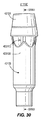
再び先の図面を参照すると、図30は、図29の実施形態による、ゴルフクラブヘッド21101(図29)から分離されたシャフトスリーブ411100の側面図を示す。一方、図31は、図29の実施形態による、図30の線XXXIII−XXXIIIに沿ったシャフトスリーブ411100の断面図を示す。
Referring again to the previous drawing, FIG. 30 shows a side view of the
図30を参照すると、シャフトスリーブ411100は、シャフトスリーブ本体42103及びシャフトスリーブキャップ42104を有する。更に、多くの実施形態では、シャフトスリーブ本体22103は、スリーブ本体外壁423130から突出している1つ以上のカプラを有するスリーブカプラセット423110を有することができ、シャフトレシーバ413200(図29)は、シャフトスリーブ411100のスリーブカプラセット423110に係合し、シャフトレシーバ413200に対するシャフトスリーブ411100の回転を制限するように構成されたレシーバカプラセットを有してもよい。これら又は他の実施形態では、スリーブカプラセット413110はスリーブカプラセット3110(図3)に類似してもよく、スリーブ本体外壁423130はスリーブ外壁3130(図3)に類似してもよく、及び/又はレシーバカプラセットはレシーバカプラセット3210(図3)に類似してもよい。以下で更に詳細に説明するように、多くの実施形態では、シャフトスリーブキャップ42104はフェルールを有することができ、シャフトスリーブ本体42103をゴルフクラブシャフト41102(図29)と結合するように動作可能であってもよい。
Referring to FIG. 30, the
一方、ここで図31を参照すると、シャフトスリーブ411100は、(i)ゴルフクラブシャフト41102の端部(図29)を受け入れるように構成されたシャフト穴433120、(ii)スリーブ本体下端部433192にある固定用締結具穴43105、(iii)穴底面43111、(iv)ゴルフクラブシャフト41102の端部を受け入れ、シャフト穴433120に結合するように構成されたキャップ穴42110、及び/又は(v)シャフトスリーブ上端部431191を有してもよい。シャフトスリーブ411100をシャフトレシーバ413200(図29)に固定するために、固定用締結具穴43105は固定用締結具(図示せず)を受け入れるように構成されてもよい。更に、穴底面43111はシャフト穴432120の底面(例えば、最深面)を有してもよい。多くの実施形態では、シャフト穴433120はシャフト穴3120(図3)に類似してもよく、固定用締結具穴43105は、固定用締結具3400(図3)を受け入れるように構成された穴と類似するかもしくは同一であってもよく、スリーブ本体下端部433192はスリーブ下端部3192(図3)と類似するかもしくは同一であってもよく、固定用締結具は固定用締結具3400(図3)と類似するかもしくは同一であってもよく、及び/又はシャフトスリーブ上端部431191はスリーブ上端部1191(図3)と類似するかもしくは同一であってもよい。
On the other hand, referring now to FIG. 31, the
更に、シャフトスリーブ本体42103がシャフトスリーブキャップ42104に結合される場合、シャフトスリーブ411100は、シャフトスリーブ高さ43119と、シャフトスリーブ本体高さ43120と、シャフトスリーブキャップ高さ43121と、シャフトスリーブキャップ上部高さ43122と、を有してもよい。シャフトスリーブ高さ43119は、スリーブ本体下端部433192にほぼ垂直に測定した、スリーブ本体下端部433192からシャフトスリーブ上端部431191までの距離を意味してもよい。一方、シャフトスリーブ本体高さ43120は、シャフトスリーブ高さ43119に平行に測定した、スリーブ本体下端部433192からシャフトスリーブ本体42103の上端部までの距離を意味してもよい。シャフトスリーブキャップ高さ43121は、シャフトスリーブ高さ43119に平行に測定した、シャフトスリーブキャップ42104の下部からシャフトスリーブ上端部431191までの距離を意味してもよい。更に、シャフトスリーブキャップ上部高さ43122は、シャフトスリーブ高さ43119とシャフトスリーブ本体高さ43120との間の差を意味してもよい。
Further, when the
例えば、シャフトスリーブ高さ43119は、約1.78インチ以上、約1.82インチ以下であってもよい。特定の例では、シャフトスリーブ高さ43119は、約1.8インチであってもよい。
For example, the
更に、シャフトスリーブ本体高さ43120は、約1.529インチ以上、約1.569インチ以下であってもよい。特定の例では、シャフトスリーブ本体高さ43120は、約1.549インチであってもよい。
Further, the shaft
更にまた、シャフトスリーブキャップ高さ43121は、約0.46インチ以上、約0.50インチ以下であってもよい。特定の例では、シャフトスリーブキャップ高さ43121は、約0.48インチであってもよい。
Furthermore, the shaft
一方、例えば、シャフトスリーブキャップ上部高さ43122は、約0.23インチ以上、約0.27インチ以下であってもよい。特定の例では、シャフトスリーブ本体高さ43122は、約0.25インチであってもよい。
On the other hand, for example, the shaft sleeve cap
いくつかの実施形態では、固定用締結具穴23105に挿入するための固定用締結具(図示せず)はチタン被覆鋼を含んでもよい。更に、固定用締結具は固定用締結具質量を有してもよい。固定用締結具質量は、約2.7グラム以上であってもよい。
In some embodiments, a fastening fastener (not shown) for insertion into the
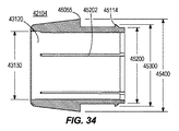
次の図面を参照すると、図32は、図29の実施形態による、シャフトスリーブキャップ42104(図30)から分離されたシャフトスリーブ本体42103の側面図を示す。シャフトスリーブ本体42103は、1つ以上の領域44106に関連してもよい。例えば、領域44106は、締結具領域44107と、中間領域44108と、カプラ領域44109と、キャップインターフェース領域44110とを有してもよい。
Referring to the following drawings, FIG. 32 shows a side view of the
締結具領域44107は、スリーブ本体下端部433192と穴底面43111(図31)との間に位置するシャフトスリーブ本体42103の一部分を意味してもよい。一方、カプラ領域44109は、スリーブカプラセット423110の最下点(例えば、スリーブ本体下端部433192(図31)に最も近いスリーブカプラセット423110の点)から、スリーブカプラセット423110の最高点(例えば、スリーブ本体下端部433192から最も遠いスリーブカプラセット423110の点)まで位置するシャフトスリーブ本体の一部分を意味してもよい。一方、中間領域44108は、締結具領域44107とカプラ領域44109との間のシャフトスリーブ本体42103の一部分を意味してもよい。キャップインターフェース領域44110は、中間領域44108に対してカプラ領域44109の反対側にあるシャフトスリーブ本体42103の一部分を意味してもよい。更に図32を参照すると、キャップインターフェース領域44110(図32)は上部リング44115(図32)を更に有してもよい。
The
ゴルフクラブヘッド41101(図29)がスイングされたとき及び/又はゴルフボールを打つように操作されたとき、締結具領域44107及びカプラ領域44109は高い応力を受ける可能性がある。一方、中間領域44108及び/又はキャップインターフェース領域44110は、締結具領域44107及びカプラ領域44109が受ける高い応力よりも低い応力を受ける可能性がある。
When the golf club head 41101 (FIG. 29) is swung and / or manipulated to strike a golf ball, the
固定用締結具によってシャフトスリーブ411100(図29)をシャフトレシーバ413200(図29)に固定することで、締結具領域44107における高い応力の相殺を補助することができる。更に、カプラ領域44109において受ける可能性のある高い応力のため、スリーブカプラセット423110のカプラは、シャフトスリーブ本体42103のスリーブ本体壁に付加的な厚みを付与するように構成されたソリッドローブを有してもよい。したがって、カプラはスリーブ本体壁をカプラ領域44109において強化し、カプラ領域44109におけるこれらの高い応力を相殺することができる。スリーブカプラセット423110のカプラは(例えば、直線的に又は曲線的に)勾配することができ、スリーブ本体下端部433192から最も遠いカプラ領域44109の端部に(例えば、カプラ領域44109がキャップインターフェース領域44110と接続する位置)最大厚さを有し、スリーブ本体下端部433192(図31)に最も近いカプラ領域44109の端部(例えば、カプラ領域44109が中間領域44108と接続する位置)に最小厚さを有する。例えば、最大厚さは約0.75インチの厚さであってもよい。最小厚さは約0.020インチの厚さであってもよい。多くの実施形態では、スリーブカプラセット423110(図30)のカプラを勾配させることで、中間領域44108とキャップインターフェース領域44110との間に連続性(例えば、厚みの滑らかな移行)を提供することができる。
By fixing the shaft sleeve 411100 (FIG. 29) to the shaft receiver 413200 (FIG. 29) with a fixing fastener, high stress cancellation in the
いくつかの実施形態では、スリーブカプラセット423110のカプラは輪郭が対称であってもよい。スリーブカプラセット423110のカプラの長さは約0.38インチ以下であってもよく(例えば、シャフトスリーブ本体42103のスリーブ本体外壁423130の一部)、約0.26インチ以上であってもよい(例えば、シャフトスリーブ本体42103のスリーブ本体外壁423130の別の部分)。
In some embodiments, the couplers in the sleeve coupler set 423110 may be symmetrical in profile. The coupler length of the sleeve coupler set 423110 may be about 0.38 inches or less (eg, a portion of the sleeve body
いくつかの実施形態では、カプラは、シャフトスリーブ本体42103のスリーブ本体外壁423130の第1部分の方が別の部分(例えば、第1部分に正対するか又は180度対向する部分)よりも長くなるように、スリーブカプラセット423110のカプラは輪郭が非対称であってもよい。スリーブカプラセット423110のカプラの長さは約0.38インチ以下であってもよく(例えば、シャフトスリーブ本体42103のスリーブ本体外壁423130の部分)、約0.260インチ以上であってもよい(例えば、シャフトスリーブ本体42103のスリーブ本体外壁423130の別の部分)。多くの実施形態では、スリーブカプラセット423110(図30)のカプラは、スリーブ本体下端部433192から最も遠いカプラ領域44109(図32)の端部(例えば、カプラ領域44109がキャップインターフェース領域44110と接続する位置)における、シャフトスリーブ本体42103のスリーブ軸に最も近いシャフトスリーブ本体42103のスリーブ本体外壁423130の部分において最長であってもよい。スリーブ軸は、スリーブ軸5150(図5)と類似するかもしくは同一であってもよい。換言すると、スリーブカプラセット423110(図30)のカプラは、スリーブ軸を有し、スリーブ本体下端部433192にほぼ垂直に延びる面に交差するシャフトスリーブ本体42103のスリーブ本体外壁423130の部分において最長であってもよい。
In some embodiments, the coupler has a first portion of the sleeve body
一方、ゴルフクラブヘッド41101がスイングされたとき及び/又はゴルフボールを打つように操作されたとき、中間領域44108が受ける応力はより低くなることから、シャフトスリーブ本体のスリーブ本体壁はカプラ領域44109の一部もしくは全体よりも中間領域44108においてより薄くされてもよく、及び/又は中間領域44108は穴もしくは凹部を有することにより中間領域44108の重量を低減してもよい。例えば、中間領域44108におけるシャフトスリーブ本体42103のスリーブ本体壁は、約0.020インチの厚さ(例えば、平均厚さ)を有してもよい。
On the other hand, when the
ここで図31に戻ると、いくつかの実施形態では、シャフトスリーブ本体42103は幅(例えば、外径)を有してもよい。シャフトスリーブ本体42103の外径は約0.405インチ以上、約0.445インチ以下であってもよい。特定の例では、シャフトスリーブ本体の外径は、0.425インチであってもよい。
Returning now to FIG. 31, in some embodiments, the
いくつかの実施形態では、シャフト穴は幅(例えば、直径)(図31)を有してもよい。シャフト穴433120の直径は、シャフト穴の中間から穴底面43111まで減少してもよい。穴キャップの直径は中間シャフト穴433130の直径と類似するか又は同じであってもよい。穴下部43150の直径は、約0.320インチ以上、約0.360インチ以下であってもよい。特定の例では、穴下部の直径は、0.340インチであってもよい。中間シャフト穴433130の直径は、約0.326インチ以上、0.366インチ以下であってもよい。特定の例では、中間シャフト穴433130の直径は、0.346インチであってもよい。キャップ穴42115の直径は、約0.326インチ以上、0.366インチ以下であってもよい。特定の例では、キャップ穴42115の直径は、0.346インチであってもよい。
In some embodiments, the shaft hole may have a width (eg, diameter) (FIG. 31). The diameter of the
種々の実施形態では、シャフトスリーブ本体42103は、エッチングチャネル43112をシャフト穴433120に有し、ゴルフクラブシャフト41102(図29)をシャフトスリーブ本体42103にエポキシ接着するためのより適切な表面積を付与することができる。エッチングチャネル43112は、カプラ領域44109(図32)に、及び/又は例えばカプラ領域44109(図32)に近い方の中間領域44108(図32)の半分など、中間領域44108(図32)の一部もしくは全体に配置されてもよい。
In various embodiments, the
これら又は他の実施形態では、シャフトスリーブ本体42103は、受け入れ溝43113(例えば、アンダーカットノッチ)を有してもよい。以下で更に詳細に説明するように、受け入れ溝43113(図31)は、シャフトスリーブキャップ42104の突出部45114(図33)と連通して相互係止し、シャフトスリーブキャップ42104をシャフトスリーブ本体42103に固定することができる。したがって、多くの実施形態では、シャフトスリーブ本体42103の受け入れ溝43113(図34)は突出部45114(図33)を補完することができる。いくつかの実施形態では、受け入れ溝43113は、キャップインターフェース領域44110(図32)に配置されてもよい。多くの実施形態では、受け入れ溝43113(図35B)は、キャップインターフェース領域44110(図32)とカプラ領域44109(図32)(図31も参照)との境界面に配置されてもよい。
In these or other embodiments, the
ここで先の図面を参照すると、図33Aは、図29の実施形態による、シャフトスリーブ本体42103(図30)から分離されたシャフトスリーブキャップ42104の直立側面図を示す。図33Bは、図29の実施形態による、シャフトスリーブ本体42103(図30)から分離されたシャフトスリーブキャップ42104の有角上面図を示す。図34は、図29の実施形態による、図33Aの線XLV−XLVに沿ったシャフトスリーブキャップ42104の断面図を示す。シャフトスリーブキャップ42104は、キャップ壁45040(図33A)を更に有してもよい。キャップ壁は、キャップ壁の一端にある外部キャップ壁45115と、外部キャップ壁に対向する内部キャップ壁45120とを有してもよい。
Referring now to the previous drawings, FIG. 33A shows an upright side view of the
図33Aを参照すると、シャフトスリーブキャップ42104は、上部キャップ領域45050と、下部キャップ領域45060とを有してもよい。上部キャップ領域45050は、上部キャップ領域45050の上部にある上部リング45045と、上部キャップ領域45050の下端部にある下部縁端シェルフ45055とを有してもよい。上部キャップ領域45050は、上部から下部へと下部縁端シェルフ45055まで直径が増加する。下部キャップ領域45060は、上部キャップ領域45050よりも小さい外径を有する。
Referring to FIG. 33A, the
下部キャップ領域45060は、外部キャップ壁45115から突出している突出部45114を有してもよい。突出部45114は、外部キャップ壁45115(図34)から延出するリップを有してもよい。したがって、突出部45114は、下部キャップ領域45060のキャップ壁の残部の幅45200及び/又はシャフト穴43120(図33A及び図34)の直径よりも大きい幅(例えば、直径)45300を有してもよい。上部キャップ領域45050の下端部シェルフ45055の幅45400は、下部キャップ領域45060(図34)の突出部45114の幅45300よりも大きい。
The
シャフトスリーブキャップ41204の下部キャップ領域45060は、シャフトスリーブ本体42103(図32)のキャップインターフェース領域44110及びカプラ領域44109内に嵌合する。一実施形態では、シャフトスリーブキャップ41204をシャフトスリーブ本体42103に結合する及びシャフトスリーブ本体42103から分離するために、シャフトスリーブキャップ41204の下部キャップ領域45060の突出部45114は、受け入れ溝43113(図34)内及び外に配置されてもよい。受け入れ溝43113(図34)は、下部キャップ領域45060の突出部45114(図33)を補完することができる。これらの実施形態では、突出部45115はロック機能として動作可能であるか、又はシャフトスリーブ本体42103(図32)の受け入れ溝43113(図34)間の適所にスナップ留めされてもよい。いくつかの実施形態では、突出部45115は、上向きの角度で延出することができ、シャフトスリーブキャップ41204がシャフトスリーブ本体42103(図32)内に取り付けられるときに曲げることを可能にする。更に図32を参照すると、シャフトスリーブキャップ41204をシャフトスリーブ本体42103内に取り付けると、シャフトスリーブキャップ42104の下端部シェルフ45055は、シャフトスリーブ本体42103(図32)のキャップインターフェース領域の上部リング44115の上に取り付けられる。
The
シャフトスリーブキャップ42104は、シャフト穴43120(図33B)を有してもよい。シャフト穴直径43130は、上部キャップ領域45050及び下部キャップ領域45060(図34)の両方の全体にわたり一定である。シャフトスリーブキャップ42104(上部及び下部領域)と、シャフトスリーブ本体42103のキャップインターフェース領域44110及びカプラ領域44109と、を組み合わせることで、組立プロセス時におけるエポキシの浸出を防止する。
The
シャフトスリーブキャップ42104は、1つ以上のリブ45202を有してもよい。1つ以上のリブ45202は、シャフトスリーブキャップ42104のシャフト穴43120内に、内部キャップ壁45120に沿って上部キャップ領域45050から下部キャップ領域45060(図33B)まで互いに平行に突出するか又は延びる。リブ45202は付加的な密閉を提供することができ、シャフトスリーブキャップ41204をシャフトスリーブ本体42103に確実に結合することができる。リブ45202は、シャフトスリーブ411100内におけるゴルフクラブのシャフト41102の確実な調心を更に提供することができる。
The
シャフトスリーブキャップ42104は、シャフトスリーブキャップ42104のないシャフトスリーブ本体42103と比較して安定性を提供する。(1)シャフトスリーブキャップ42104の全体的な設計、(2)シャフトスリーブキャップ42104の内部キャップ壁45120上のリブ45202、(3)シャフトスリーブキャップ42104の外部キャップ壁45115上の突出部45115、(4)シャフトスリーブ本体42103の受け入れ溝43113、及び(5)シャフト穴の中間からシャフトスリーブ本体42103の穴底面43111まで減少する穴直径を組み合わせることで、個々に又はその任意の組み合わせにおいて、ゴルフクラブのシャフト41102をシャフトスリーブ411100の上部及び下部の両方内において中央に位置決めすることができ、図29のシャフト41102により向上した安定性を提供することができる。調心により、ゴルフクラブシャフトの同心性が増し、ゴルフクラブヘッドのスイング時及びゴルフボールとのインパクトの際にシャフトにかかる応力を低減する。
The
これらの要素はまた、単独で又はその組み合わせにおいて、ゴルフクラブシャフト41102(図29)とシャフトスリーブ本体42103(図29)との間の減衰(例えば、振動)及び応力低減を与える。例えば、シャフトスリーブキャップ42104は、シャフトスリーブ本体42103(図31)内におけるゴルフクラブシャフト41102(図30)の同心性を増すことによって「シャフトピロー」として機能してもよい。多くの実施形態では、シャフトスリーブ本体42103(図30)内におけるゴルフクラブシャフト41102(図29)の同心性は、ゴルフクラブシャフト41102(図31)の耐久性と強い相関関係があってもよい。したがって、(1)シャフトスリーブキャップ42104の内部キャップ壁45120上のリブ45202、(2)シャフトスリーブキャップ42104の外部キャップ壁45115上の突出部45115、(3)シャフトスリーブ本体42103の受け入れ溝43113、及び(4)シャフト穴の中間からシャフトスリーブ本体42103の穴底面43111まで減少する穴直径は、個々に又はその任意の組み合わせにおいて、シャフトスリーブキャップ42104は、ゴルフクラブシャフト41102(図29)の破損を防ぐことができ、ゴルフクラブヘッド41101(図29)の全体的な寿命を増加することができる。
These elements also, alone or in combination, provide damping (eg, vibration) and stress reduction between the golf club shaft 41102 (FIG. 29) and the shaft sleeve body 42103 (FIG. 29). For example, the
再度図30を参照すると、シャフトスリーブ本体42103は、任意の適切な材料を含んでもよい。例えば、いくつかの実施形態では、シャフトスリーブ本体22103は、金属又は金属合金(例えば、アルミニウム合金)を含んでもよい。これらの例では、アルミニウム合金は、約70%以上のアルミニウム及び約75%以下のアルミニウムを含んでもよい。より具体的な例では、アルミニウム合金は、約70%、71%、72%、73%、74%又は75%のアルミニウムを含んでもよい。
Referring again to FIG. 30, the
シャフトスリーブキャップ42104は、上述のようにキャップ壁25115(図25)が弾性的に圧縮するのを可能とするように構成された任意の適切な材料を含んでもよい。例えば、シャフトスリーブキャップ22104は、ポリマープラスチック材料を含んでもよい。ポリマープラスチック材料は、熱可塑性プラスチック材料又はショアDデュロメータスケールによるソフトポリマープラスチックであってもよい。ソフトポリマープラスチックは、ショアDデュロメータスケールで40、45、50、55又は60以下であってもよい。ソフトポリマープラスチックは、ショアDデュロメータスケールで55以下であってもよい。ポリマープラスチック材料は、ポリスチレン、塩化ビニル、ポリ塩化ビニル、ナイロン、ポリメタクリレート、ゴム、ポリカーボネート、合成ゴム又はこれらのコポリマーからなってもよい。
The
多くの実施形態では、シャフトスリーブ本体42103は、シャフトスリーブ本体質量を有することができ、シャフトスリーブキャップ42104は、シャフトスリーブキャップ質量を有することができる。更に、シャフトスリーブ411100は、シャフトスリーブ本体質量及びシャフトスリーブキャップ質量を有するシャフトスリーブ質量を有してもよい。シャフトスリーブ質量は、スリーブ1100(図1)に関して上述したスリーブの質量に類似してもよい。
In many embodiments, the
これら又は他の実施形態では、シャフトスリーブ質量は、約4.0グラム以上、約4.1グラム以上、約4.2グラム以上、約4.3グラム以上、約4.4グラム以上、約4.5グラム以上、約4.6グラム以上、約4.7グラム以上、約4.8グラム以上、約4.9グラム以上又は約5.0グラム以上であってもよい。更に、シャフトスリーブ本体質量は、約4.2グラム以上、約4.8グラム以下であってもよい。シャフトスリーブ本体質量は、4.5グラムであってもよい。更にまた、シャフトスリーブキャップ質量は、約3.8グラム以上、約3.9グラム以上、約4.0グラム以上、約4.1グラム以上、約4.2グラム以上、約4.3グラム以上又は約4.4グラム以上であってもよい。シャフトスリーブキャップ質量は、約0.1グラム以上、約0.7グラム以下であってもよい。種々の実施形態では、シャフトスリーブ質量は、スリーブ1100の質量(図1)よりも約0.4グラム少なくされてもよい。更に、固定用締結具質量と合わせたシャフトスリーブ質量は、約7.2グラム以上であってもよい。したがって、種々の実施形態では、シャフトスリーブ411100は、シャフトスリーブ1100(図1)よりも重量の優位性を提供することができる。
In these or other embodiments, the shaft sleeve mass is about 4.0 grams or more, about 4.1 grams or more, about 4.2 grams or more, about 4.3 grams or more, about 4.4 grams or more, about 4 It may be greater than 0.5 grams, greater than about 4.6 grams, greater than about 4.7 grams, greater than about 4.8 grams, greater than about 4.9 grams, or greater than about 5.0 grams. Further, the shaft sleeve body mass may be greater than or equal to about 4.2 grams and less than or equal to about 4.8 grams. The shaft sleeve body mass may be 4.5 grams. Furthermore, the shaft sleeve cap mass is greater than about 3.8 grams, greater than about 3.9 grams, greater than about 4.0 grams, greater than about 4.1 grams, greater than about 4.2 grams, greater than about 4.3 grams. Or it may be about 4.4 grams or more. The shaft sleeve cap mass may be about 0.1 grams or more and about 0.7 grams or less. In various embodiments, the shaft sleeve mass may be about 0.4 grams less than the mass of the sleeve 1100 (FIG. 1). Further, the shaft sleeve mass combined with the fastener fastener mass may be greater than or equal to about 7.2 grams. Thus, in various embodiments, the
図29を参照すると、ゴルフクラブヘッド41101は、分解後クラブヘッド質量及び組立後クラブヘッド質量を有してもよい。分解後クラブヘッド質量は、ゴルフクラブヘッド101(図1)に関して上述した分解後クラブヘッド質量に類似してもよく、組立後クラブヘッド質量は、ゴルフクラブヘッド101(図1)に関して上述した組立後クラブヘッド質量に類似してもよい。
Referring to FIG. 29, a
いくつかの実施形態では、分解後クラブヘッド質量は、約185グラム以上、約205グラム以下であってもよい。これら又は他の実施形態では、分解後クラブヘッド質量は、約192グラム以上であってもよい。 In some embodiments, the club head mass after disassembly may be greater than or equal to about 185 grams and less than or equal to about 205 grams. In these or other embodiments, the club head mass after disassembly may be about 192 grams or more.
いくつかの実施形態では、組立後クラブヘッド質量は、約188グラム以上、約213グラム以下であってもよい。これら又は他の実施形態では、組立後クラブヘッド質量は、約199グラム以上であってもよい。 In some embodiments, the post-assembly club head mass may be greater than or equal to about 188 grams and less than or equal to about 213 grams. In these or other embodiments, the post-assembly club head mass may be greater than or equal to about 199 grams.
更に、分解後クラブヘッド質量に対するシャフトスリーブ質量の比は、約2.0%、2.2%又は2.4%以下であってもよい。組立後クラブヘッド質量に対するシャフトスリーブ質量の比は、約1.95%、2.16%又は2.35%以下であってもよく、分解後クラブヘッド質量に対するシャフトスリーブ質量及び固定用締結具質量の比は、約3.4%、3.6%又は3.8%以下であってもよく、及び/又は組立後クラブヘッド質量に対するシャフトスリーブ質量及び固定用締結具質量の比は、約3.3%、3.5%又は3.7%以下であってもよい。 Further, the ratio of the shaft sleeve mass to the club head mass after disassembly may be about 2.0%, 2.2% or 2.4% or less. The ratio of the shaft sleeve mass to the club head mass after assembly may be about 1.95%, 2.16% or 2.35% or less, and the shaft sleeve mass and fixing fastener mass to the club head mass after disassembly. The ratio of the shaft sleeve mass and the fastening fastener mass to the post-assembly club head mass may be about 3%, 3.6%, or 3.8% or less. It may be .3%, 3.5% or 3.7% or less.
一方、ゴルフクラブヘッド41101は、組立後のクラブヘッドCG垂直距離に関連する組立後のクラブヘッドCGを有することができ、シャフトスリーブ411100は、シャフトスリーブCG垂直距離に関連するシャフトスリーブCGを有することができる。これらの実施形態では、組立後のクラブヘッドCGは、組立後のクラブヘッドCG1050(図1)と類似するかもしくは同一であってもよく、組立後のクラブヘッドCG垂直距離は、組立後のクラブヘッドCG垂直距離1058(図1)と類似するかもしくは同一であってもよく、シャフトスリーブCGはシャフトスリーブCG1032(図1)と類似するかもしくは同一であってもよく、及び/又はシャフトスリーブCG垂直距離は、また、クラブヘッド(図1)の下部から測定した、シャフトスリーブCG垂直距離1159と類似するかもしくは同一であってもよい。
On the other hand, the
多くの実施形態では、シャフトスリーブ411100(図31)のシャフトスリーブCG垂直距離は、シャフトスリーブ211100(図23)のシャフトスリーブCG垂直距離よりも約0.052インチ(約1.32ミリメートル)以上、0.092インチ(約2.34ミリメートル)以下だけ少ないものとされてもよい。シャフトスリーブ411100(図31)のシャフトスリーブCG垂直距離は、シャフトスリーブCG垂直距離1159(図1)よりも約0.042インチ(約1.07ミリメートル)以上、0.062インチ(約1.58ミリメートル)以下であってもよい。ゴルフカップリング機構411000のシャフトスリーブCG垂直距離は、ゴルフクラブヘッド41101のソール下端部から約43.5ミリメートル以上、ゴルフクラブヘッド41101のソール下端部から約47.0ミリメートル以下であってもよい。いくつかの実施形態では、ゴルフカップリング機構411000のシャフトスリーブCG垂直距離は、ゴルフクラブヘッド41101のソール下端部から約43.5ミリメートル以上、約43.6ミリメートル以上、約43.7ミリメートル以上、約43.8ミリメートル以上、約43.9ミリメートル以上、約44.0ミリメートル以上、約44.1ミリメートル以上、約44.2ミリメートル以上、約44.3ミリメートル以上、約44.4ミリメートル以上、約44.5ミリメートル以上、約44.6ミリメートル以上、約44.7ミリメートル以上、約44.8ミリメートル以上、約44.9ミリメートル以上、約45.0ミリメートル以上、約45.1ミリメートル以上、約45.2ミリメートル以上、約45.3ミリメートル以上、約45.4ミリメートル以上、約45.5ミリメートル以上、約45.6ミリメートル以上、約45.7ミリメートル以上、約45.8ミリメートル以上、約45.9ミリメートル以上、約46.0ミリメートル以上、約46.1ミリメートル以上、約46.2ミリメートル以上、約46.3ミリメートル以上、約46.4ミリメートル以上、約46.5ミリメートル以上、約46.6ミリメートル以上、約46.7ミリメートル以上、約46.8ミリメートル以上、約46.9ミリメートル、又は約47.0ミリメートル以上であってもよい。いくつかの実施形態では、ゴルフカップリング機構411000のシャフトスリーブCG垂直距離は、ゴルフクラブヘッド41101のソール下端部から約43.5ミリメートル以下、約43.6ミリメートル以下、約43.7ミリメートル以下、約43.8ミリメートル以下、約43.9ミリメートル以下、約44.0ミリメートル以下、約44.1ミリメートル以下、約44.2ミリメートル以下、約44.3ミリメートル以下、約44.4ミリメートル以下、約44.5ミリメートル以下、約44.6ミリメートル以下、約44.7ミリメートル以下、約44.8ミリメートル以下、約44.9ミリメートル以下、約45.0ミリメートル以下、約45.1ミリメートル以下、約45.2ミリメートル以下、約45.3ミリメートル以下、約45.4ミリメートル以下、約45.5ミリメートル以下、約45.6ミリメートル以下、約45.7ミリメートル以下、約45.8ミリメートル以下、約45.9ミリメートル以下、約46.0ミリメートル以下、約46.1ミリメートル以下、約46.2ミリメートル以下、約46.3ミリメートル以下、約46.4ミリメートル以下、約46.5ミリメートル以下、約46.6ミリメートル以下、約46.7ミリメートル以下、約46.8ミリメートル以下、約46.9ミリメートル以下、又は約47.0ミリメートル以下であってもよい。ゴルフカップリング機構411000のシャフトスリーブCG垂直距離は、ゴルフクラブヘッド41101のソール下端部から45.3ミリメートルであってもよい。ソール下端部は、ソール下端部10141(図1)と類似するか又は同一であってもよい。
In many embodiments, the shaft sleeve CG vertical distance of the shaft sleeve 411100 (FIG. 31) is about 0.052 inches (about 1.32 millimeters) or greater than the shaft sleeve CG vertical distance of the shaft sleeve 211100 (FIG. 23); It may be less than 0.092 inches (about 2.34 millimeters) or less. The shaft sleeve CG vertical distance of the shaft sleeve 411100 (FIG. 31) is more than about 0.042 inches (about 1.07 millimeters) and 0.062 inches (about 1.58) than the shaft sleeve CG vertical distance 1159 (FIG. 1). Mm) or less. The shaft sleeve CG vertical distance of the
いくつかの実施形態では、ゴルフカップリング機構411000のシャフトスリーブCG垂直距離は、ゴルフクラブヘッド41101のソール下端部から約32.0ミリメートル以上、約32.1ミリメートル以上、約32.3ミリメートル以上、約32.4ミリメートル以上、約32.5ミリメートル以上、約32.6ミリメートル以上、約32.7ミリメートル以上、約32.8ミリメートル以上、約32.9ミリメートル以上、約33.0ミリメートル以上、約33.1ミリメートル以上、約33.2ミリメートル以上、約33.3ミリメートル以上、約33.4ミリメートル以上、約33.5ミリメートル以上、約33.6ミリメートル以上、約33.7ミリメートル以上、約33.8ミリメートル以上、約33.9ミリメートル以上、約34.0ミリメートル以上、約34.1ミリメートル以上、約34.2ミリメートル以上、約34.3ミリメートル以上、約34.4ミリメートル、又は約34.5ミリメートル以上であってもよい。ゴルフカップリング機構411000のシャフトスリーブCG垂直距離は、ゴルフクラブヘッド41101のソール下端部から約32.0ミリメートル以下、約32.1ミリメートル以下、約32.3ミリメートル以下、約32.4ミリメートル以下、約32.5ミリメートル以下、約32.6ミリメートル以下、約32.7ミリメートル以下、約32.8ミリメートル以下、約32.9ミリメートル以下、約33.0ミリメートル以下、約33.1ミリメートル以下、約33.2ミリメートル以下、約33.3ミリメートル以下、約33.4ミリメートル以下、約33.5ミリメートル以下、約33.6ミリメートル以下、約33.7ミリメートル以下、約33.8ミリメートル以下、約33.9ミリメートル以下、約34.0ミリメートル以下、約34.1ミリメートル以下、約34.2ミリメートル以下、約34.3ミリメートル以下、約34.4ミリメートル以下、又は約34.5ミリメートル以下であってもよい。ゴルフカップリング機構のシャフトスリーブCG垂直距離は、ゴルフクラブヘッド41101のソール下端部から33.6ミリメートルであってもよい。
In some embodiments, the shaft sleeve CG vertical distance of the
先の図面を参照すると、図36は、一実施形態による方法47000のフローチャートを示す。多くの実施形態では、方法47000は、ゴルフクラブヘッドの1つ以上の部品のゴルフクラブヘッドの製造方法を有してもよい。ゴルフクラブヘッドは、ゴルフクラブヘッド41101(図29)と類似するか又は同一であってもよい。
Referring to the previous drawing, FIG. 36 shows a flowchart of a
方法47000は、シャフトスリーブを用意する作業47001を有してもよい。シャフトスリーブは、シャフトスリーブ411100(図30)と類似するか又は同一であってもよい。図36は、図36の実施形態による例示的な作業47001を示す。
The
例えば、図36において、作業47001は、シャフトスリーブ本体を用意(例えば、製造)する作業48001を有してもよい。シャフトスリーブ本体はシャフトスリーブ本体42103(図37)と類似するか又は同一であってもよい。
For example, in FIG. 36,
更に、作業47002は、シャフトスリーブキャップを用意(例えば、製造)する作業48002を有してもよい。シャフトスリーブキャップは、シャフトスリーブキャップ42104(図38)と類似0するか又は同一であってもよい。
Further,
ここで再度図36を参照すると、方法47000は、ゴルフクラブヘッドを用意(例えば、製造)する作業47002を有してもよい。ゴルフクラブヘッドは、ゴルフクラブヘッド41101(図29)と類似するか又は同一であってもよい。いくつかの実施形態では、作業47001は、作業47002の前及びその逆で実施されてもよい。他の実施形態では、作業47001と作業47002は、ほぼ同時に実施されてもよい。
Referring now again to FIG. 36, the
更に、方法47000は、シャフトスリーブをゴルフクラブヘッドのホーゼル穴に挿入する作業47003を有してもよい。ホーゼル穴は、ゴルフクラブヘッド41101(図29)に関して上述したホーゼル穴と類似するか又は同一であってもよい。
Further, the
また、方法4700は、ゴルフクラブシャフトをシャフト穴に挿入する作業47004を有してもよい。ゴルフクラブシャフトはゴルフクラブシャフト41102(図29)と類似するか又は同一であってもよく、及びシャフト穴はシャト穴433120(図31)と類似するか又は同一であってもよい。
The method 47700 may also include an
一方、方法47000は、シャフトスリーブキャップをシャフト穴に挿入する作業47005を有してもよい。いくつかの実施形態では、作業47004は、作業47005の前に又はその逆で実施されてもよい。他の実施形態では、作業47004と作業47005は、ほぼ同時に実施されてもよい。更なる実施形態では、作業47003は、作業47004及び/又は作業47005の前並びにその逆で実施されてもよい。多くの実施形態では、作業47001〜47003の1つ以上は、作業47004〜47005の1つ以上の前に、又はその逆で(図37)実施されてもよい。
On the other hand,
更にまた、方法47000は、シャフトスリーブを締結具によってゴルフクラブヘッドのホーゼルに固定する作業47006を有してもよい。ホーゼルは、ゴルフクラブヘッド41101(図31)に関して上述したホーゼルと類似するか又は同一であってもよく、及び締結具は、ゴルフクラブヘッド21101(図31)に関して上述した締結具と類似するか又は同一であってもよい。
Still further, the
本明細書では、ゴルフカップリング機構及び関連する方法を特定の実施形態を参照して記載してきたが、本開示の趣旨又は範囲から逸脱することなく種々の変更形態がなされてもよい。一例として、スリーブカプラセット3110(図3〜図7、図10、図14〜図17)、スリーブカプラセット12110(図12)、スリーブカプラセット223110(図22)及び/又はスリーブカプラセット411100が、2つのスリーブカプラのみを有し得る実施形態、並びにレシーバカプラセット3210(図3〜図4、図8〜図9、図11、図14〜図17)、レシーバカプラセット13210(図13)、シャフトレシーバ213200(図21)のレシーバカプラセット及び/又はシャフトレシーバ413200(図29)のレシーバカプラセットが、2つのレシーバカプラのみを有し得る実施形態があってもよい。このような実施形態では、シャフトスリーブとシャフトレシーバとの間において2つの構成のみが可能であってもよく、ゴルフカプラセットは2つのライ角又は2つのロフト角間における調節を可能にしてもよい。当然のことながら、3つ、5つ、6つ、7つ、8つ、又はそれを超えるスリーブカプラを有するスリーブカプラセットと、3つ、5つ、6つ、7つ、8つ又はそれを超えるレシーバカプラを有するレシーバカプラセットと、を有し、これに対応して、可能なライ角とロフト角との組み合わせの数が増加する実施形態もあってもよい。 Although the golf coupling mechanism and related methods have been described herein with reference to specific embodiments, various modifications can be made without departing from the spirit or scope of the present disclosure. As an example, a sleeve coupler set 3110 (FIGS. 3 to 7, 10, 14 to 17), a sleeve coupler set 12110 (FIG. 12), a sleeve coupler set 223110 (FIG. 22), and / or a sleeve coupler set 411100, Embodiments that may have only two sleeve couplers, as well as receiver coupler set 3210 (FIGS. 3-4, 8-9, 11, 14-17), receiver coupler set 13210 (FIG. 13), shaft There may be embodiments where the receiver coupler set of receiver 213200 (FIG. 21) and / or the receiver coupler set of shaft receiver 413200 (FIG. 29) may have only two receiver couplers. In such embodiments, only two configurations may be possible between the shaft sleeve and the shaft receiver, and the golf coupler set may allow adjustment between two lie angles or two loft angles. Of course, a sleeve coupler set having three, five, six, seven, eight or more sleeve couplers and three, five, six, seven, eight or more There may be embodiments in which the number of possible lie angle and loft angle combinations is increased correspondingly with a receiver coupler set having more receiver couplers.
このような変更形態及びその他の更なる例を前述の説明において記載してきた。種々の図の特徴の1つ以上を有する異なる実施形態の他の置換形態も同様に企図される。したがって、本明細書、本明細書の特許請求の範囲及び図面は本開示の範囲の例示を意図するものであり、限定を意図するものではない。本出願の範囲は添付の特許請求の範囲によって要求される程度にのみ限定されるものとする。 Such modifications and other further examples have been described in the foregoing description. Other permutations of different embodiments having one or more of the various figure features are contemplated as well. Accordingly, the specification, claims and drawings of the specification are intended to be illustrative of the scope of the disclosure and are not intended to be limiting. The scope of this application shall be limited only to the extent required by the appended claims.
本明細書中に記載されるゴルフカップリング機構及び関連する方法は種々の実施形態において実施してもよく、これらの実施形態のうちの特定のものに関する前述の説明は、可能なあらゆる実施形態の完全な説明を必ずしも意味するものではない。むしろ、図面の詳細な説明及び図面自体が少なくとも1つの好適な実施形態を開示するとともに、代替的な実施形態を開示する場合がある。 The golf coupling mechanisms and associated methods described herein may be implemented in various embodiments, and the foregoing description of certain of these embodiments is for all possible embodiments. It does not necessarily mean a complete description. Rather, the detailed description of the drawings and the drawings themselves disclose at least one preferred embodiment and may disclose alternative embodiments.
加えて、特定の実施形態に関する利益、他の利点及び課題の解決策を記載してきた。しかしながら、任意の利益、利点又は解決策が生じるか又はより顕著になる原因となり得る利益、利点、課題の解決策及び1つもしくは複数のあらゆる要素は、このような利益、利点、解決策又は要素がこのような特許請求の範囲において特に明示されない限り、特許請求の範囲の一部又は全部の重要である必要な又は必須の特徴又は要素として解釈されるべきではない。 In addition, benefits, other advantages, and solutions to problems with particular embodiments have been described. However, any benefit, advantage, solution to the problem and any one or more factors that may cause or become more significant any benefit, advantage or solution are such benefits, advantages, solutions or elements. Unless expressly stated otherwise in such claims, they should not be construed as essential or essential features or elements of any or all of the claims.
ゴルフのルールはしばしば変更される場合がある(例えば、全米ゴルフ協会(USGA)、英国ゴルフ協会(R&A)等など、ゴルフ規格協会及び/又は運営団体によって新たな規定が採用される場合があるか、又は古いルールが排除もしくは変更される場合がある)ため、本明細書中に記載される装置、方法及び製造物品に関連するゴルフ用具は任意の特定の時点のゴルフのルールに適合するか又は適合しない場合がある。したがって、本明細書中に記載される装置、方法及び製造物品に関連するゴルフ用具は、適合するもしくは適合しないゴルフ用具として広告され、販売に供され、及び/又は販売されてもよい。本明細書中に記載される装置、方法及び製造物品はこの点に関して限定されるものではない。 Golf rules may change frequently (for example, new rules may be adopted by golf standards associations and / or governing bodies such as the United States Golf Association (USGA), the British Golf Association (R & A), etc.) Golf equipment associated with the devices, methods and articles of manufacture described herein may conform to any particular point-in-time golf rules or May not fit. Accordingly, golf equipment associated with the devices, methods, and articles of manufacture described herein may be advertised, offered for sale, and / or sold as conforming or non-conforming golf equipment. The apparatus, methods and articles of manufacture described herein are not limited in this regard.
上記例はドライバー型ゴルフクラブに関連して記載されている場合があるが、本明細書中に記載される装置、方法及び製造物品は、フェアウェイウッド型ゴルフクラブ、ハイブリッド型ゴルフクラブ、アイアン型ゴルフクラブ、ウェッジ型ゴルフクラブ又はパター型ゴルフクラブなどの他の種類のゴルフクラブに適用可能であってもよい。或いは、本明細書中に記載される装置、方法及び製造物品は、ホッケースティック、テニスラケット、釣竿、スキーポール等などの他の種類のスポーツ用具に適用可能であってもよい。 Although the above examples may be described in the context of driver-type golf clubs, the devices, methods, and articles of manufacture described herein are fairway wood-type golf clubs, hybrid-type golf clubs, iron-type golfs. It may be applicable to other types of golf clubs such as clubs, wedge type golf clubs or putter type golf clubs. Alternatively, the devices, methods and articles of manufacture described herein may be applicable to other types of sports equipment such as hockey sticks, tennis rackets, fishing rods, ski poles and the like.
更に、本明細書中に開示される実施形態及び限定は、その実施形態及び/又は限定が、(1)請求項において明示的に特許請求されておらず、(2)均等論の下で請求項中の明示的な要素及び/もしくは限定の潜在的な均等物である場合、公有の原則(doctrine of dedication)の下で公共に供されることはない。 Further, the embodiments and limitations disclosed herein are not explicitly claimed in (1) the claims, and (2) claimed under the doctrine of equivalents. If it is an explicit element and / or potential equivalent of a limitation in a paragraph, it will not be made available to the public under a documentary of decision.
Claims (18)
ソール下端部を含むソール部と、前記ソール部に対向するトップ部と、ヒール部と、前記ヒール部に対向するトウ部と、リア部と、前記リア部に対向するフロント部であって、打面を含む前記フロント部と、ホーゼルと、を有するクラブヘッド本体と、
前記ホーゼルに挿入可能であり、ゴルフクラブシャフトを前記ホーゼルと結合するように構成されたシャフトスリーブと、
前記シャフトスリーブを前記ホーゼル内に固定するために、前記シャフトスリーブのスリーブ下端部に結合するように構成された固定用締結具と、を備えており、
前記ホーゼルは、前記シャフトスリーブを受け入れるように構成されたホーゼル穴を有しており、
前記シャフトスリーブは、
前記ゴルフクラブシャフトの端部を受け入れるように構成されたシャフト穴と、
スリーブ本体外壁と、前記スリーブ本体外壁にある少なくとも1つのカプラと、受け入れ溝と、を有するシャフトスリーブ本体と、
前記シャフトスリーブ本体と結合されるように構成されたシャフトスリーブキャップと、を有しており、
前記シャフトスリーブキャップは、キャップ穴と、キャップ壁と、前記キャップ壁から外側へ伸びるリップと、を有しており、
前記キャップ穴の内面は、前記ゴルフクラブシャフトと相互作用する1つ以上の調心機能部を有しており、
前記キャップ壁は、前記キャップ壁を弾性的に圧縮する1つ以上のスリットを有しており、
前記シャフトスリーブキャップの前記リップは、前記シャフトスリーブ本体の前記受け入れ溝と係合し、
前記クラブヘッド本体はさらに、前記クラブヘッド本体が前記シャフトスリーブ及び前記固定用締結具とともに組み立てられたときに、組立後クラブヘッド重心を有し、
前記組立後クラブヘッド重心が、前記ソール下端部に対する組立後クラブヘッドCG垂直距離に位置しており、
前記シャフトスリーブが前記ホーゼル内に固定された状態で、前記ゴルフクラブヘッドがアドレス位置にあるとき、シャフトスリーブ重心が、前記ソール下端部に対して約46.5ミリメートル以下のシャフトスリーブCG垂直距離に位置しており、前記シャフトスリーブCG垂直距離が、前記組立後クラブヘッドCG垂直距離よりも少なくとも約7.6mm大きい、
ゴルフクラブヘッド。 A golf club head,
A sole portion including a lower end portion of the sole, a top portion facing the sole portion, a heel portion, a toe portion facing the heel portion, a rear portion, and a front portion facing the rear portion, A club head body having the front portion including a surface and a hosel;
A shaft sleeve insertable into the hosel and configured to couple a golf club shaft with the hosel;
A fastening fastener configured to be coupled to a sleeve lower end of the shaft sleeve to secure the shaft sleeve in the hosel;
The hosel has a hosel hole configured to receive the shaft sleeve;
The shaft sleeve is
A shaft hole configured to receive an end of the golf club shaft;
A shaft sleeve body having a sleeve body outer wall, at least one coupler in the sleeve body outer wall, and a receiving groove ;
A shaft sleeve cap configured to be coupled to the shaft sleeve body;
The shaft sleeve cap has a cap hole, a cap wall, and a lip extending outward from the cap wall;
The inner surface of the cap hole has one or more alignment function parts that interact with the golf club shaft,
The cap wall has one or more slits that elastically compress the cap wall;
The lip of the shaft sleeve cap engages the receiving groove of the shaft sleeve body;
The club head body further has a club head center of gravity after assembly when the club head body is assembled with the shaft sleeve and the fastening fastener;
The post-assembly club head center of gravity is located at a post-assembly club head CG vertical distance with respect to the lower end of the sole,
With the shaft sleeve fixed in the hosel and when the golf club head is in the address position, the shaft sleeve center of gravity is at a shaft sleeve CG vertical distance of about 46.5 mm or less with respect to the lower end of the sole. The shaft sleeve CG vertical distance is at least about 7.6 mm greater than the post-assembly club head CG vertical distance;
Golf club head.
前記シャフトスリーブ本体は、スリーブ本体壁を有しており、
前記スリーブ本体壁は、前記中間領域において、約0.020インチの中間領域厚さを有する、請求項1に記載のゴルフクラブヘッド。 The shaft sleeve body has an intermediate region;
The shaft sleeve body has a sleeve body wall;
The golf club head of claim 1, wherein the sleeve body wall has an intermediate region thickness of about 0.020 inches in the intermediate region.
前記シャフトスリーブ本体は、スリーブ本体壁を有しており、
前記スリーブ本体壁は、前記カプラ領域において、前記スリーブ本体壁の最大厚さから前記スリーブ本体壁の最小厚さへと変化するカプラ領域厚さを有しており、
前記スリーブ本体壁の前記最大厚さは約0.75インチ以下であり、
前記スリーブ本体壁の前記最小厚さは約0.020インチ以上である、請求項1に記載のゴルフクラブヘッド。 The shaft sleeve body has a coupler region;
The shaft sleeve body has a sleeve body wall;
The sleeve body wall has a coupler region thickness that varies from a maximum thickness of the sleeve body wall to a minimum thickness of the sleeve body wall in the coupler region;
The maximum thickness of the sleeve body wall is about 0.75 inches or less;
The golf club head of claim 1, wherein the minimum thickness of the sleeve body wall is about 0.020 inches or greater.
前記ホーゼル穴が前記シャフトスリーブを受け入れると、前記少なくとも1つのカプラは前記少なくとも1つのレシーバに係合して、前記ホーゼルに対する前記シャフトスリーブの回転を制限する、請求項1に記載のゴルフクラブヘッド。 The hosel hole has at least one receiver configured to engage the at least one coupler;
The golf club head of claim 1, wherein when the hosel hole receives the shaft sleeve, the at least one coupler engages the at least one receiver to limit rotation of the shaft sleeve relative to the hosel.
前記複数のカプラは、第1のカプラ及び第2のカプラを有しており、
前記第1のカプラのカプラ長さは、前記第2のカプラのカプラ長さと同じである、請求項1に記載のゴルフクラブヘッド。 The at least one coupler has a plurality of couplers;
The plurality of couplers include a first coupler and a second coupler,
The golf club head according to claim 1, wherein a coupler length of the first coupler is the same as a coupler length of the second coupler.
前記カプラ長さは、約0.260インチ以上、約0.38インチ以下である、請求項1に記載のゴルフクラブヘッド。 The at least one coupler has a coupler length;
The golf club head of claim 1, wherein the coupler length is about 0.260 inches or greater and about 0.38 inches or less.
前記シャフトスリーブ本体が前記シャフトスリーブキャップと結合されると、前記受け入れ溝が前記突出部を受け入れるように構成されている、請求項1に記載のゴルフクラブヘッド。 Before Symbol shaft sleeve cap has a protruding portion,
The golf club head of claim 1, wherein the receiving groove is configured to receive the protrusion when the shaft sleeve body is coupled to the shaft sleeve cap.
前記少なくとも1つのリブは、前記シャフトスリーブキャップに確実に結合し、前記シャフトスリーブキャップを中央に位置決めするように構成されている、請求項1に記載のゴルフクラブヘッド。 The shaft sleeve cap has at least invite Bed,
The golf club head of claim 1, wherein the at least one rib is configured to securely couple to the shaft sleeve cap and position the shaft sleeve cap in the center.
前記シャフト穴が前記ゴルフクラブシャフトの前記端部を受け入れると、前記1つ以上のリブが、前記ゴルフクラブシャフトを前記シャフト穴内において中央に位置決めする、請求項1に記載のゴルフクラブヘッド。 The shaft sleeve cap, one or more re blanking extending Previous Symbol cap holes have a,
The golf club head of claim 1, wherein the one or more ribs center the golf club shaft within the shaft hole when the shaft hole receives the end of the golf club shaft.
前記シャフトスリーブ本体は、約4.1グラム以下のシャフトスリーブ本体質量を有するか、
前記シャフトスリーブキャップは、約0.3グラム以上、約1.0グラム以下のシャフトスリーブキャップ質量を有するか、
の少なくとも1つである、請求項1に記載のゴルフクラブヘッド。 The shaft sleeve has a shaft sleeve mass of about 4.5 grams;
The shaft sleeve body has a shaft sleeve body mass of about 4.1 grams or less;
The shaft sleeve cap has a shaft sleeve cap mass of about 0.3 grams or more and about 1.0 grams or less;
The golf club head of claim 1, wherein the golf club head is at least one of the following.
前記組立後クラブヘッド質量は、約199グラム以下である、請求項1に記載のゴルフクラブヘッド。 When the shaft sleeve cap is coupled to the shaft sleeve body and the fastener secures the shaft sleeve to the hosel, the golf club head has a club head mass after assembly;
The golf club head of claim 1, wherein the assembled club head mass is about 199 grams or less.
前記シャフトスリーブは、シャフトスリーブ質量を有しており、
前記組立後クラブヘッド質量に対する前記シャフトスリーブ質量の比は約2.2%以下である、請求項1に記載のゴルフクラブヘッド。 When the shaft sleeve cap is coupled to the shaft sleeve body and the fastener secures the shaft sleeve to the hosel, the golf club head has a club head mass after assembly;
The shaft sleeve has a shaft sleeve mass;
The golf club head of claim 1, wherein a ratio of the shaft sleeve mass to the assembled club head mass is about 2.2% or less.
前記シャフトスリーブは、シャフトスリーブ質量を有しており、
前記分解後クラブヘッド質量に対する前記シャフトスリーブ質量の比は約2.3%以下である、請求項1に記載のゴルフクラブヘッド。 The golf club head has a club head mass after disassembly,
The shaft sleeve has a shaft sleeve mass;
The golf club head of claim 1, wherein a ratio of the shaft sleeve mass to the post-decomposition club head mass is about 2.3% or less.
前記シャフトスリーブ本体が前記シャフトスリーブキャップに結合されると、前記シャフトスリーブはシャフトスリーブ本体高さを有し、前記シャフトスリーブ本体高さが約1.529インチ以上、約1.569インチ以下であるか、
前記シャフトスリーブ本体が前記シャフトスリーブキャップに結合されると、前記シャフトスリーブはシャフトスリーブキャップ高さを有し、前記シャフトスリーブキャップ高さが約0.46インチ以上、約0.50インチ以下であるか、
の少なくとも1つである、請求項1に記載のゴルフクラブヘッド。 When the shaft sleeve body is coupled to the shaft sleeve cap, the shaft sleeve has a shaft sleeve height, and the shaft sleeve height is greater than or equal to about 1.78 inches and less than or equal to about 1.82 inches;
When the shaft sleeve body is coupled to the shaft sleeve cap, the shaft sleeve has a shaft sleeve body height, and the shaft sleeve body height is not less than about 1.529 inches and not more than about 1.569 inches. Or
When the shaft sleeve body is coupled to the shaft sleeve cap, the shaft sleeve has a shaft sleeve cap height, and the shaft sleeve cap height is about 0.46 inches or more and about 0.50 inches or less. Or
The golf club head of claim 1, wherein the golf club head is at least one of the following.
ソール下端部を含むソール部と、前記ソール部に対向するトップ部と、ヒール部と、前記ヒール部に対向するトウ部と、リア部と、前記リア部に対向するフロント部であって、打面を含む前記フロント部と、ホーゼルと、を有するクラブヘッド本体と、
前記ホーゼルに挿入可能であり、ゴルフクラブシャフトを前記ホーゼルと結合するように構成されたシャフトスリーブと、
前記シャフトスリーブを前記ホーゼル内に固定するために、前記シャフトスリーブのスリーブ下端部に結合するように構成された固定用締結具と、を備えており、
前記ホーゼルは、前記シャフトスリーブを受け入れるように構成されたホーゼル穴を有しており、
前記シャフトスリーブは、
前記ゴルフクラブシャフトの端部を受け入れるように構成されたシャフト穴と、
スリーブ本体外壁と、前記スリーブ本体外壁上の少なくとも1つのカプラと、を有するシャフトスリーブ本体と、
前記シャフトスリーブ本体と結合されるように構成されたシャフトスリーブキャップと、を有しており、
前記シャフトスリーブ本体は、中間領域及びスリーブ本体壁をさらに有しており、
前記シャフトスリーブは、約4.5グラムのシャフトスリーブ質量を有しており、
前記シャフトスリーブ本体は、約4.1グラム以下のシャフトスリーブ本体質量を有しており、
前記シャフトスリーブキャップは、キャップ穴と、キャップ壁と、前記キャップ穴内へと延びる1つ以上のリブと、を有しており、
前記シャフト穴が前記ゴルフクラブシャフトの前記端部を受け入れると、前記1つ以上のリブは、前記ゴルフクラブシャフトを前記シャフト穴内において中央に位置決めし、
前記シャフトスリーブキャップは、前記シャフトスリーブ本体と着脱可能に結合されており、
前記キャップ壁は、前記シャフトスリーブキャップを前記シャフトスリーブ本体へ挿抜するときに、前記キャップ壁を弾性的に圧縮する1つ以上のスリットを有しており、
前記クラブヘッド本体はさらに、前記クラブヘッド本体が前記シャフトスリーブ及び前記固定用締結具とともに組み立てられたときに、組立後クラブヘッド重心を有し、
前記組立後クラブヘッド重心が、前記ソール下端部に対する組立後クラブヘッドCG垂直距離に位置しており、
前記シャフトスリーブが前記ホーゼル内に固定された状態で前記ゴルフクラブヘッドがアドレス位置にあるとき、シャフトスリーブ重心が、前記ソール下端部に対して、約43.5ミリメートル以上、約47.0ミリメートル以下のシャフトスリーブCG垂直距離に位置しており、前記シャフトスリーブCG垂直距離が、前記組立後クラブヘッドCG垂直距離よりも少なくとも約7.6mm大きい、ゴルフクラブヘッド。 A golf club head,
A sole portion including a lower end portion of the sole, a top portion facing the sole portion, a heel portion, a toe portion facing the heel portion, a rear portion, and a front portion facing the rear portion, A club head body having the front portion including a surface and a hosel;
A shaft sleeve insertable into the hosel and configured to couple a golf club shaft with the hosel;
A fastening fastener configured to be coupled to a sleeve lower end of the shaft sleeve to secure the shaft sleeve in the hosel;
The hosel has a hosel hole configured to receive the shaft sleeve;
The shaft sleeve is
A shaft hole configured to receive an end of the golf club shaft;
A shaft sleeve body having a sleeve body outer wall and at least one coupler on the sleeve body outer wall;
A shaft sleeve cap configured to be coupled to the shaft sleeve body;
The shaft sleeve body further comprises an intermediate region and a sleeve body wall;
The shaft sleeve has a shaft sleeve mass of about 4.5 grams;
The shaft sleeve body has a shaft sleeve body mass of about 4.1 grams or less;
The shaft sleeve cap has a cap hole, a cap wall, and one or more ribs extending into the cap hole;
When the shaft hole receives the end of the golf club shaft, the one or more ribs center the golf club shaft within the shaft hole;
The shaft sleeve cap is detachably coupled to the shaft sleeve body,
The cap wall has one or more slits that elastically compress the cap wall when the shaft sleeve cap is inserted into and removed from the shaft sleeve body.
The club head body further has a club head center of gravity after assembly when the club head body is assembled with the shaft sleeve and the fastening fastener;
The post-assembly club head center of gravity is located at a post-assembly club head CG vertical distance with respect to the lower end of the sole,
When the golf club head is in the address position with the shaft sleeve fixed in the hosel, the center of gravity of the shaft sleeve is about 43.5 millimeters or more and about 47.0 millimeters or less with respect to the lower end portion of the sole. A shaft sleeve CG vertical distance, wherein the shaft sleeve CG vertical distance is at least about 7.6 mm greater than the post-assembly club head CG vertical distance.
Applications Claiming Priority (5)
| Application Number | Priority Date | Filing Date | Title |
|---|---|---|---|
| US201562107240P | 2015-01-23 | 2015-01-23 | |
| US62/107,240 | 2015-01-23 | ||
| US201562254081P | 2015-11-11 | 2015-11-11 | |
| US62/254,081 | 2015-11-11 | ||
| PCT/US2016/014322 WO2016118748A1 (en) | 2015-01-23 | 2016-01-21 | Golf clubs with hosel inserts and related methods |
Related Child Applications (1)
| Application Number | Title | Priority Date | Filing Date |
|---|---|---|---|
| JP2019136345A Division JP6715999B2 (en) | 2015-01-23 | 2019-07-24 | Golf club with hosel insert and related methods |
Publications (3)
| Publication Number | Publication Date |
|---|---|
| JP2018503448A JP2018503448A (en) | 2018-02-08 |
| JP2018503448A5 JP2018503448A5 (en) | 2019-02-28 |
| JP6563502B2 true JP6563502B2 (en) | 2019-08-21 |
Family
ID=56417744
Family Applications (5)
| Application Number | Title | Priority Date | Filing Date |
|---|---|---|---|
| JP2017538682A Active JP6563502B2 (en) | 2015-01-23 | 2016-01-21 | Golf club with hosel insert and related method |
| JP2019136345A Active JP6715999B2 (en) | 2015-01-23 | 2019-07-24 | Golf club with hosel insert and related methods |
| JP2020100336A Active JP6959403B2 (en) | 2015-01-23 | 2020-06-09 | Golf clubs with hosel inserts and related methods |
| JP2021165737A Active JP7227330B2 (en) | 2015-01-23 | 2021-10-07 | Golf clubs with hosel inserts and related methods |
| JP2023018532A Active JP7506205B2 (en) | 2015-01-23 | 2023-02-09 | Golf club with hosel insert |
Family Applications After (4)
| Application Number | Title | Priority Date | Filing Date |
|---|---|---|---|
| JP2019136345A Active JP6715999B2 (en) | 2015-01-23 | 2019-07-24 | Golf club with hosel insert and related methods |
| JP2020100336A Active JP6959403B2 (en) | 2015-01-23 | 2020-06-09 | Golf clubs with hosel inserts and related methods |
| JP2021165737A Active JP7227330B2 (en) | 2015-01-23 | 2021-10-07 | Golf clubs with hosel inserts and related methods |
| JP2023018532A Active JP7506205B2 (en) | 2015-01-23 | 2023-02-09 | Golf club with hosel insert |
Country Status (4)
| Country | Link |
|---|---|
| JP (5) | JP6563502B2 (en) |
| KR (4) | KR102424406B1 (en) |
| GB (3) | GB2589525B (en) |
| WO (1) | WO2016118748A1 (en) |
Families Citing this family (2)
| Publication number | Priority date | Publication date | Assignee | Title |
|---|---|---|---|---|
| KR101851986B1 (en) * | 2017-04-14 | 2018-04-25 | 이종은 | Iron club fitting device |
| DE102017007857A1 (en) * | 2017-08-23 | 2019-02-28 | Deckel Maho Pfronten Gmbh | Spindle device for use on a numerically controlled machine tool |
Family Cites Families (23)
| Publication number | Priority date | Publication date | Assignee | Title |
|---|---|---|---|---|
| JPH1176470A (en) * | 1997-09-10 | 1999-03-23 | Yamaha Corp | Golf club |
| US6752726B2 (en) * | 2002-03-18 | 2004-06-22 | Burrows Golf, Llc | Slotted hosel for a golf club |
| US8303431B2 (en) * | 2008-05-16 | 2012-11-06 | Taylor Made Golf Company, Inc. | Golf club |
| US6652388B1 (en) * | 2003-01-29 | 2003-11-25 | Callaway Golf Company | Method and apparatus for assembling a shaft to a golf club head and a golf club having such assembly |
| JP2006042951A (en) * | 2004-08-02 | 2006-02-16 | Seiko S-Yard Co Ltd | Golf club |
| JP4808562B2 (en) * | 2006-07-31 | 2011-11-02 | グローブライド株式会社 | Golf club |
| JP5029120B2 (en) * | 2007-04-24 | 2012-09-19 | 横浜ゴム株式会社 | Golf club |
| US7789766B2 (en) * | 2008-01-31 | 2010-09-07 | Acushnet Company | Interchangeable shaft system |
| JP5225767B2 (en) * | 2008-06-26 | 2013-07-03 | ダンロップスポーツ株式会社 | Golf club |
| US8287400B2 (en) * | 2009-11-19 | 2012-10-16 | Nike, Inc. | Fairway wood-type golf clubs with high moment of inertia |
| US8535173B2 (en) * | 2010-10-25 | 2013-09-17 | Acushnet Company | Golf club with improved performance |
| US8684859B1 (en) * | 2011-03-10 | 2014-04-01 | Callaway Golf Company | Adjustable golf club shaft and hosel assembly |
| US8480511B2 (en) | 2011-07-15 | 2013-07-09 | Taylor Made Golf Company, Inc. | Methods for marking golf club ferrule |
| US8926447B2 (en) | 2011-08-31 | 2015-01-06 | Karsten Manufacturing Corporation | Golf coupling mechanisms and related methods |
| US8790191B2 (en) * | 2011-08-31 | 2014-07-29 | Karsten Manufacturing Corporation | Golf coupling mechanisms and related methods |
| US9192823B2 (en) | 2011-08-31 | 2015-11-24 | Karsten Manufacturing Corporation | Golf coupling mechanisms and related methods |
| US8932147B2 (en) | 2011-08-31 | 2015-01-13 | Karsten Maunfacturing Corporation | Golf coupling mechanisms and related methods |
| JP5720630B2 (en) * | 2012-06-28 | 2015-05-20 | ヤマハ株式会社 | Golf club |
| JP6074220B2 (en) * | 2012-10-17 | 2017-02-01 | ダンロップスポーツ株式会社 | Golf club head |
| JP5997622B2 (en) * | 2013-01-30 | 2016-09-28 | ダンロップスポーツ株式会社 | Golf club |
| US9028341B2 (en) | 2013-03-11 | 2015-05-12 | Taylor Made Golf Company, Inc. | Golf club head |
| JP6313634B2 (en) * | 2014-04-01 | 2018-04-18 | 株式会社本間ゴルフ | Golf club |
| JP3194703U (en) * | 2014-09-25 | 2014-12-04 | 復盛應用科技股▲分▼有限公司 | Adjustable golf club head |
-
2016
- 2016-01-21 KR KR1020217015244A patent/KR102424406B1/en active IP Right Grant
- 2016-01-21 GB GB2102876.6A patent/GB2589525B/en active Active
- 2016-01-21 KR KR1020237032344A patent/KR20230136712A/en active IP Right Grant
- 2016-01-21 GB GB2014877.1A patent/GB2588517B/en active Active
- 2016-01-21 GB GB1711735.9A patent/GB2550082B/en active Active
- 2016-01-21 JP JP2017538682A patent/JP6563502B2/en active Active
- 2016-01-21 KR KR1020227025138A patent/KR102582705B1/en active IP Right Grant
- 2016-01-21 KR KR1020177023491A patent/KR102256675B1/en active Application Filing
- 2016-01-21 WO PCT/US2016/014322 patent/WO2016118748A1/en active Application Filing
-
2019
- 2019-07-24 JP JP2019136345A patent/JP6715999B2/en active Active
-
2020
- 2020-06-09 JP JP2020100336A patent/JP6959403B2/en active Active
-
2021
- 2021-10-07 JP JP2021165737A patent/JP7227330B2/en active Active
-
2023
- 2023-02-09 JP JP2023018532A patent/JP7506205B2/en active Active
Also Published As
| Publication number | Publication date |
|---|---|
| GB2588517B (en) | 2021-09-22 |
| KR102424406B1 (en) | 2022-07-22 |
| KR102582705B1 (en) | 2023-09-22 |
| GB201711735D0 (en) | 2017-09-06 |
| WO2016118748A1 (en) | 2016-07-28 |
| KR102256675B1 (en) | 2021-05-27 |
| GB202102876D0 (en) | 2021-04-14 |
| JP7227330B2 (en) | 2023-02-21 |
| GB202014877D0 (en) | 2020-11-04 |
| GB2550082B (en) | 2020-11-04 |
| KR20170105611A (en) | 2017-09-19 |
| JP2022008968A (en) | 2022-01-14 |
| GB2588517A (en) | 2021-04-28 |
| JP2019205850A (en) | 2019-12-05 |
| JP2023055945A (en) | 2023-04-18 |
| KR20220104314A (en) | 2022-07-26 |
| GB2550082A (en) | 2017-11-08 |
| JP6959403B2 (en) | 2021-11-02 |
| JP6715999B2 (en) | 2020-07-01 |
| GB2589525B (en) | 2021-09-22 |
| JP2018503448A (en) | 2018-02-08 |
| KR20230136712A (en) | 2023-09-26 |
| JP7506205B2 (en) | 2024-06-25 |
| KR20210060680A (en) | 2021-05-26 |
| JP2020142145A (en) | 2020-09-10 |
| GB2589525A (en) | 2021-06-02 |
Similar Documents
| Publication | Publication Date | Title |
|---|---|---|
| US11013964B2 (en) | Golf clubs with hosel inserts and related methods | |
| US11083936B2 (en) | Golf club head or other ball striking device having impact-influencing body features | |
| JP6752265B2 (en) | Golf club heads and related methods | |
| US9662551B2 (en) | Golf club head or other ball striking device having impact-influencing body features | |
| CA2788064C (en) | Golf coupling mechanisms and related methods | |
| JP7506205B2 (en) | Golf club with hosel insert | |
| CA2788184A1 (en) | Golf coupling mechanisms and related methods | |
| US20230338785A1 (en) | Golf clubs with hosel inserts and related methods | |
| US10004952B2 (en) | Golf coupling mechanisms and related methods | |
| US20230226416A1 (en) | Golf clubs with hosel inserts and related methods |
Legal Events
| Date | Code | Title | Description |
|---|---|---|---|
| A521 | Request for written amendment filed |
Free format text: JAPANESE INTERMEDIATE CODE: A523 Effective date: 20190118 |
|
| A621 | Written request for application examination |
Free format text: JAPANESE INTERMEDIATE CODE: A621 Effective date: 20190118 |
|
| A871 | Explanation of circumstances concerning accelerated examination |
Free format text: JAPANESE INTERMEDIATE CODE: A871 Effective date: 20190118 |
|
| A521 | Request for written amendment filed |
Free format text: JAPANESE INTERMEDIATE CODE: A523 Effective date: 20190201 |
|
| A975 | Report on accelerated examination |
Free format text: JAPANESE INTERMEDIATE CODE: A971005 Effective date: 20190207 |
|
| A131 | Notification of reasons for refusal |
Free format text: JAPANESE INTERMEDIATE CODE: A131 Effective date: 20190219 |
|
| A521 | Request for written amendment filed |
Free format text: JAPANESE INTERMEDIATE CODE: A821 Effective date: 20190201 |
|
| A521 | Request for written amendment filed |
Free format text: JAPANESE INTERMEDIATE CODE: A523 Effective date: 20190516 |
|
| TRDD | Decision of grant or rejection written | ||
| A01 | Written decision to grant a patent or to grant a registration (utility model) |
Free format text: JAPANESE INTERMEDIATE CODE: A01 Effective date: 20190625 |
|
| A61 | First payment of annual fees (during grant procedure) |
Free format text: JAPANESE INTERMEDIATE CODE: A61 Effective date: 20190724 |
|
| R150 | Certificate of patent or registration of utility model |
Ref document number: 6563502 Country of ref document: JP Free format text: JAPANESE INTERMEDIATE CODE: R150 |
|
| R250 | Receipt of annual fees |
Free format text: JAPANESE INTERMEDIATE CODE: R250 |
|
| R250 | Receipt of annual fees |
Free format text: JAPANESE INTERMEDIATE CODE: R250 |
|
| R250 | Receipt of annual fees |
Free format text: JAPANESE INTERMEDIATE CODE: R250 |