JP6562319B2 - Nanocarbon polymer actuator - Google Patents
Nanocarbon polymer actuator Download PDFInfo
- Publication number
- JP6562319B2 JP6562319B2 JP2017536390A JP2017536390A JP6562319B2 JP 6562319 B2 JP6562319 B2 JP 6562319B2 JP 2017536390 A JP2017536390 A JP 2017536390A JP 2017536390 A JP2017536390 A JP 2017536390A JP 6562319 B2 JP6562319 B2 JP 6562319B2
- Authority
- JP
- Japan
- Prior art keywords
- thin film
- conductive thin
- cnt
- cnh
- pani
- Prior art date
- Legal status (The legal status is an assumption and is not a legal conclusion. Google has not performed a legal analysis and makes no representation as to the accuracy of the status listed.)
- Active
Links
- 229920000642 polymer Polymers 0.000 title claims description 38
- 229910021392 nanocarbon Inorganic materials 0.000 title 1
- OKTJSMMVPCPJKN-UHFFFAOYSA-N Carbon Chemical compound [C] OKTJSMMVPCPJKN-UHFFFAOYSA-N 0.000 claims description 133
- 229920000767 polyaniline Polymers 0.000 claims description 103
- 239000002041 carbon nanotube Substances 0.000 claims description 100
- 229910021393 carbon nanotube Inorganic materials 0.000 claims description 100
- 239000010409 thin film Substances 0.000 claims description 84
- 239000002608 ionic liquid Substances 0.000 claims description 47
- 239000003792 electrolyte Substances 0.000 claims description 46
- 229910052799 carbon Inorganic materials 0.000 claims description 30
- 239000002116 nanohorn Substances 0.000 claims description 26
- 239000012528 membrane Substances 0.000 claims description 19
- 239000010408 film Substances 0.000 claims description 4
- 239000000463 material Substances 0.000 claims description 2
- 239000004927 clay Substances 0.000 claims 1
- -1 tetrafluoroborate ion Chemical class 0.000 description 20
- 238000006073 displacement reaction Methods 0.000 description 17
- 239000002904 solvent Substances 0.000 description 14
- 230000000052 comparative effect Effects 0.000 description 12
- VNWKTOKETHGBQD-UHFFFAOYSA-N methane Chemical compound C VNWKTOKETHGBQD-UHFFFAOYSA-N 0.000 description 12
- 238000000034 method Methods 0.000 description 10
- 230000008602 contraction Effects 0.000 description 9
- 125000000217 alkyl group Chemical group 0.000 description 7
- 229920005569 poly(vinylidene fluoride-co-hexafluoropropylene) Polymers 0.000 description 7
- 150000001450 anions Chemical class 0.000 description 6
- 238000011156 evaluation Methods 0.000 description 6
- 238000002156 mixing Methods 0.000 description 6
- 125000004432 carbon atom Chemical group C* 0.000 description 5
- 150000001768 cations Chemical class 0.000 description 5
- 239000006185 dispersion Substances 0.000 description 5
- 150000002500 ions Chemical class 0.000 description 5
- RUOJZAUFBMNUDX-UHFFFAOYSA-N propylene carbonate Chemical compound CC1COC(=O)O1 RUOJZAUFBMNUDX-UHFFFAOYSA-N 0.000 description 5
- 239000000243 solution Substances 0.000 description 5
- NTIZESTWPVYFNL-UHFFFAOYSA-N Methyl isobutyl ketone Chemical compound CC(C)CC(C)=O NTIZESTWPVYFNL-UHFFFAOYSA-N 0.000 description 4
- UIHCLUNTQKBZGK-UHFFFAOYSA-N Methyl isobutyl ketone Natural products CCC(C)C(C)=O UIHCLUNTQKBZGK-UHFFFAOYSA-N 0.000 description 4
- 238000005266 casting Methods 0.000 description 4
- 238000004519 manufacturing process Methods 0.000 description 4
- 238000002360 preparation method Methods 0.000 description 4
- 150000003839 salts Chemical class 0.000 description 4
- WEVYAHXRMPXWCK-UHFFFAOYSA-N Acetonitrile Chemical compound CC#N WEVYAHXRMPXWCK-UHFFFAOYSA-N 0.000 description 3
- UHOVQNZJYSORNB-UHFFFAOYSA-N Benzene Chemical compound C1=CC=CC=C1 UHOVQNZJYSORNB-UHFFFAOYSA-N 0.000 description 3
- YMWUJEATGCHHMB-UHFFFAOYSA-N Dichloromethane Chemical compound ClCCl YMWUJEATGCHHMB-UHFFFAOYSA-N 0.000 description 3
- OKKJLVBELUTLKV-UHFFFAOYSA-N Methanol Chemical compound OC OKKJLVBELUTLKV-UHFFFAOYSA-N 0.000 description 3
- FXHOOIRPVKKKFG-UHFFFAOYSA-N N,N-Dimethylacetamide Chemical compound CN(C)C(C)=O FXHOOIRPVKKKFG-UHFFFAOYSA-N 0.000 description 3
- 239000002033 PVDF binder Substances 0.000 description 3
- YXFVVABEGXRONW-UHFFFAOYSA-N Toluene Chemical compound CC1=CC=CC=C1 YXFVVABEGXRONW-UHFFFAOYSA-N 0.000 description 3
- 150000001336 alkenes Chemical class 0.000 description 3
- 230000000694 effects Effects 0.000 description 3
- 238000002347 injection Methods 0.000 description 3
- 239000007924 injection Substances 0.000 description 3
- VLKZOEOYAKHREP-UHFFFAOYSA-N n-Hexane Chemical compound CCCCCC VLKZOEOYAKHREP-UHFFFAOYSA-N 0.000 description 3
- JRZJOMJEPLMPRA-UHFFFAOYSA-N olefin Natural products CCCCCCCC=C JRZJOMJEPLMPRA-UHFFFAOYSA-N 0.000 description 3
- 229920002981 polyvinylidene fluoride Polymers 0.000 description 3
- 238000007639 printing Methods 0.000 description 3
- CSCPPACGZOOCGX-UHFFFAOYSA-N Acetone Chemical compound CC(C)=O CSCPPACGZOOCGX-UHFFFAOYSA-N 0.000 description 2
- HEDRZPFGACZZDS-UHFFFAOYSA-N Chloroform Chemical compound ClC(Cl)Cl HEDRZPFGACZZDS-UHFFFAOYSA-N 0.000 description 2
- LFQSCWFLJHTTHZ-UHFFFAOYSA-N Ethanol Chemical compound CCO LFQSCWFLJHTTHZ-UHFFFAOYSA-N 0.000 description 2
- SECXISVLQFMRJM-UHFFFAOYSA-N N-Methylpyrrolidone Chemical compound CN1CCCC1=O SECXISVLQFMRJM-UHFFFAOYSA-N 0.000 description 2
- 229920003171 Poly (ethylene oxide) Polymers 0.000 description 2
- WYURNTSHIVDZCO-UHFFFAOYSA-N Tetrahydrofuran Chemical compound C1CCOC1 WYURNTSHIVDZCO-UHFFFAOYSA-N 0.000 description 2
- 125000001931 aliphatic group Chemical group 0.000 description 2
- 125000003277 amino group Chemical group 0.000 description 2
- QVGXLLKOCUKJST-UHFFFAOYSA-N atomic oxygen Chemical compound [O] QVGXLLKOCUKJST-UHFFFAOYSA-N 0.000 description 2
- 239000003575 carbonaceous material Substances 0.000 description 2
- 239000011248 coating agent Substances 0.000 description 2
- 238000000576 coating method Methods 0.000 description 2
- 238000001035 drying Methods 0.000 description 2
- RTZKZFJDLAIYFH-UHFFFAOYSA-N ether Chemical group CCOCC RTZKZFJDLAIYFH-UHFFFAOYSA-N 0.000 description 2
- 125000001495 ethyl group Chemical group [H]C([H])([H])C([H])([H])* 0.000 description 2
- 238000001125 extrusion Methods 0.000 description 2
- 229910021389 graphene Inorganic materials 0.000 description 2
- 229910052736 halogen Inorganic materials 0.000 description 2
- 125000004435 hydrogen atom Chemical group [H]* 0.000 description 2
- 230000002209 hydrophobic effect Effects 0.000 description 2
- 125000000959 isobutyl group Chemical group [H]C([H])([H])C([H])(C([H])([H])[H])C([H])([H])* 0.000 description 2
- 125000001449 isopropyl group Chemical group [H]C([H])([H])C([H])(*)C([H])([H])[H] 0.000 description 2
- 239000007788 liquid Substances 0.000 description 2
- 125000002496 methyl group Chemical group [H]C([H])([H])* 0.000 description 2
- 239000012046 mixed solvent Substances 0.000 description 2
- 239000002048 multi walled nanotube Substances 0.000 description 2
- 125000004108 n-butyl group Chemical group [H]C([H])([H])C([H])([H])C([H])([H])C([H])([H])* 0.000 description 2
- 125000004123 n-propyl group Chemical group [H]C([H])([H])C([H])([H])C([H])([H])* 0.000 description 2
- 229910052757 nitrogen Inorganic materials 0.000 description 2
- 229910052760 oxygen Inorganic materials 0.000 description 2
- 239000001301 oxygen Substances 0.000 description 2
- 239000012071 phase Substances 0.000 description 2
- 229920003229 poly(methyl methacrylate) Polymers 0.000 description 2
- 229920002239 polyacrylonitrile Polymers 0.000 description 2
- 239000004926 polymethyl methacrylate Substances 0.000 description 2
- 230000004043 responsiveness Effects 0.000 description 2
- 125000002914 sec-butyl group Chemical group [H]C([H])([H])C([H])([H])C([H])(*)C([H])([H])[H] 0.000 description 2
- 239000002109 single walled nanotube Substances 0.000 description 2
- 125000001424 substituent group Chemical group 0.000 description 2
- 125000000542 sulfonic acid group Chemical group 0.000 description 2
- 125000000999 tert-butyl group Chemical group [H]C([H])([H])C(*)(C([H])([H])[H])C([H])([H])[H] 0.000 description 2
- 125000004642 (C1-C12) alkoxy group Chemical group 0.000 description 1
- 125000004400 (C1-C12) alkyl group Chemical group 0.000 description 1
- ZZXUZKXVROWEIF-UHFFFAOYSA-N 1,2-butylene carbonate Chemical compound CCC1COC(=O)O1 ZZXUZKXVROWEIF-UHFFFAOYSA-N 0.000 description 1
- UGFAIRIUMAVXCW-UHFFFAOYSA-N Carbon monoxide Chemical compound [O+]#[C-] UGFAIRIUMAVXCW-UHFFFAOYSA-N 0.000 description 1
- 229910020366 ClO 4 Inorganic materials 0.000 description 1
- XDTMQSROBMDMFD-UHFFFAOYSA-N Cyclohexane Chemical compound C1CCCCC1 XDTMQSROBMDMFD-UHFFFAOYSA-N 0.000 description 1
- OIFBSDVPJOWBCH-UHFFFAOYSA-N Diethyl carbonate Chemical compound CCOC(=O)OCC OIFBSDVPJOWBCH-UHFFFAOYSA-N 0.000 description 1
- SNRUBQQJIBEYMU-UHFFFAOYSA-N Dodecane Natural products CCCCCCCCCCCC SNRUBQQJIBEYMU-UHFFFAOYSA-N 0.000 description 1
- KMTRUDSVKNLOMY-UHFFFAOYSA-N Ethylene carbonate Chemical compound O=C1OCCO1 KMTRUDSVKNLOMY-UHFFFAOYSA-N 0.000 description 1
- GGMPISPXDJJENY-UHFFFAOYSA-N FC(F)(F)S(=O)(=O)[C](S(=O)(=O)C(F)(F)F)S(=O)(=O)C(F)(F)F Chemical compound FC(F)(F)S(=O)(=O)[C](S(=O)(=O)C(F)(F)F)S(=O)(=O)C(F)(F)F GGMPISPXDJJENY-UHFFFAOYSA-N 0.000 description 1
- WOBHKFSMXKNTIM-UHFFFAOYSA-N Hydroxyethyl methacrylate Chemical compound CC(=C)C(=O)OCCO WOBHKFSMXKNTIM-UHFFFAOYSA-N 0.000 description 1
- RAXXELZNTBOGNW-UHFFFAOYSA-O Imidazolium Chemical compound C1=C[NH+]=CN1 RAXXELZNTBOGNW-UHFFFAOYSA-O 0.000 description 1
- 229920000557 Nafion® Polymers 0.000 description 1
- CTQNGGLPUBDAKN-UHFFFAOYSA-N O-Xylene Chemical compound CC1=CC=CC=C1C CTQNGGLPUBDAKN-UHFFFAOYSA-N 0.000 description 1
- 239000002253 acid Substances 0.000 description 1
- 150000001298 alcohols Chemical class 0.000 description 1
- 150000001408 amides Chemical class 0.000 description 1
- 150000004945 aromatic hydrocarbons Chemical class 0.000 description 1
- 238000005452 bending Methods 0.000 description 1
- 230000015572 biosynthetic process Effects 0.000 description 1
- 239000011203 carbon fibre reinforced carbon Substances 0.000 description 1
- 229910002091 carbon monoxide Inorganic materials 0.000 description 1
- 239000011852 carbon nanoparticle Substances 0.000 description 1
- 150000004649 carbonic acid derivatives Chemical class 0.000 description 1
- 125000003178 carboxy group Chemical group [H]OC(*)=O 0.000 description 1
- 230000002925 chemical effect Effects 0.000 description 1
- 239000011370 conductive nanoparticle Substances 0.000 description 1
- 229920001940 conductive polymer Polymers 0.000 description 1
- 238000011109 contamination Methods 0.000 description 1
- 229920001577 copolymer Polymers 0.000 description 1
- 125000004093 cyano group Chemical group *C#N 0.000 description 1
- 125000004122 cyclic group Chemical group 0.000 description 1
- 230000007423 decrease Effects 0.000 description 1
- 125000002704 decyl group Chemical group [H]C([H])([H])C([H])([H])C([H])([H])C([H])([H])C([H])([H])C([H])([H])C([H])([H])C([H])([H])C([H])([H])C([H])([H])* 0.000 description 1
- IEJIGPNLZYLLBP-UHFFFAOYSA-N dimethyl carbonate Chemical compound COC(=O)OC IEJIGPNLZYLLBP-UHFFFAOYSA-N 0.000 description 1
- 238000007599 discharging Methods 0.000 description 1
- 125000003438 dodecyl group Chemical group [H]C([H])([H])C([H])([H])C([H])([H])C([H])([H])C([H])([H])C([H])([H])C([H])([H])C([H])([H])C([H])([H])C([H])([H])C([H])([H])C([H])([H])* 0.000 description 1
- 238000010325 electrochemical charging Methods 0.000 description 1
- 238000003487 electrochemical reaction Methods 0.000 description 1
- 238000005516 engineering process Methods 0.000 description 1
- 150000002170 ethers Chemical class 0.000 description 1
- JBTWLSYIZRCDFO-UHFFFAOYSA-N ethyl methyl carbonate Chemical compound CCOC(=O)OC JBTWLSYIZRCDFO-UHFFFAOYSA-N 0.000 description 1
- 238000001704 evaporation Methods 0.000 description 1
- UQSQSQZYBQSBJZ-UHFFFAOYSA-N fluorosulfonic acid Chemical compound OS(F)(=O)=O UQSQSQZYBQSBJZ-UHFFFAOYSA-N 0.000 description 1
- 229910002804 graphite Inorganic materials 0.000 description 1
- 239000010439 graphite Substances 0.000 description 1
- 150000008282 halocarbons Chemical class 0.000 description 1
- 125000005843 halogen group Chemical group 0.000 description 1
- 125000003187 heptyl group Chemical group [H]C([*])([H])C([H])([H])C([H])([H])C([H])([H])C([H])([H])C([H])([H])C([H])([H])[H] 0.000 description 1
- 125000004051 hexyl group Chemical group [H]C([H])([H])C([H])([H])C([H])([H])C([H])([H])C([H])([H])C([H])([H])* 0.000 description 1
- 238000000981 high-pressure carbon monoxide method Methods 0.000 description 1
- 229920001519 homopolymer Polymers 0.000 description 1
- 229930195733 hydrocarbon Natural products 0.000 description 1
- 125000002887 hydroxy group Chemical group [H]O* 0.000 description 1
- 150000002576 ketones Chemical class 0.000 description 1
- 238000010030 laminating Methods 0.000 description 1
- 238000002844 melting Methods 0.000 description 1
- 230000008018 melting Effects 0.000 description 1
- 210000003205 muscle Anatomy 0.000 description 1
- 125000000449 nitro group Chemical group [O-][N+](*)=O 0.000 description 1
- 125000001400 nonyl group Chemical group [H]C([*])([H])C([H])([H])C([H])([H])C([H])([H])C([H])([H])C([H])([H])C([H])([H])C([H])([H])C([H])([H])[H] 0.000 description 1
- 125000002347 octyl group Chemical group [H]C([*])([H])C([H])([H])C([H])([H])C([H])([H])C([H])([H])C([H])([H])C([H])([H])C([H])([H])[H] 0.000 description 1
- 125000001147 pentyl group Chemical group C(CCCC)* 0.000 description 1
- VLTRZXGMWDSKGL-UHFFFAOYSA-M perchlorate Chemical compound [O-]Cl(=O)(=O)=O VLTRZXGMWDSKGL-UHFFFAOYSA-M 0.000 description 1
- 230000002093 peripheral effect Effects 0.000 description 1
- 230000002572 peristaltic effect Effects 0.000 description 1
- 229920000193 polymethacrylate Polymers 0.000 description 1
- 125000001453 quaternary ammonium group Chemical group 0.000 description 1
- 239000002994 raw material Substances 0.000 description 1
- 238000005096 rolling process Methods 0.000 description 1
- 238000000527 sonication Methods 0.000 description 1
- 238000004528 spin coating Methods 0.000 description 1
- 238000005507 spraying Methods 0.000 description 1
- 238000003756 stirring Methods 0.000 description 1
- YLQBMQCUIZJEEH-UHFFFAOYSA-N tetrahydrofuran Natural products C=1C=COC=1 YLQBMQCUIZJEEH-UHFFFAOYSA-N 0.000 description 1
- 238000009210 therapy by ultrasound Methods 0.000 description 1
- 125000001889 triflyl group Chemical group FC(F)(F)S(*)(=O)=O 0.000 description 1
- 125000002948 undecyl group Chemical group [H]C([*])([H])C([H])([H])C([H])([H])C([H])([H])C([H])([H])C([H])([H])C([H])([H])C([H])([H])C([H])([H])C([H])([H])C([H])([H])[H] 0.000 description 1
- 238000001291 vacuum drying Methods 0.000 description 1
- 239000008096 xylene Substances 0.000 description 1
Images


Classifications
-
- C—CHEMISTRY; METALLURGY
- C08—ORGANIC MACROMOLECULAR COMPOUNDS; THEIR PREPARATION OR CHEMICAL WORKING-UP; COMPOSITIONS BASED THEREON
- C08L—COMPOSITIONS OF MACROMOLECULAR COMPOUNDS
- C08L79/00—Compositions of macromolecular compounds obtained by reactions forming in the main chain of the macromolecule a linkage containing nitrogen with or without oxygen or carbon only, not provided for in groups C08L61/00 - C08L77/00
- C08L79/02—Polyamines
-
- C—CHEMISTRY; METALLURGY
- C08—ORGANIC MACROMOLECULAR COMPOUNDS; THEIR PREPARATION OR CHEMICAL WORKING-UP; COMPOSITIONS BASED THEREON
- C08K—Use of inorganic or non-macromolecular organic substances as compounding ingredients
- C08K3/00—Use of inorganic substances as compounding ingredients
- C08K3/02—Elements
- C08K3/04—Carbon
- C08K3/041—Carbon nanotubes
-
- C—CHEMISTRY; METALLURGY
- C08—ORGANIC MACROMOLECULAR COMPOUNDS; THEIR PREPARATION OR CHEMICAL WORKING-UP; COMPOSITIONS BASED THEREON
- C08K—Use of inorganic or non-macromolecular organic substances as compounding ingredients
- C08K3/00—Use of inorganic substances as compounding ingredients
- C08K3/02—Elements
- C08K3/04—Carbon
- C08K3/044—Carbon nanohorns or nanobells
-
- C—CHEMISTRY; METALLURGY
- C08—ORGANIC MACROMOLECULAR COMPOUNDS; THEIR PREPARATION OR CHEMICAL WORKING-UP; COMPOSITIONS BASED THEREON
- C08L—COMPOSITIONS OF MACROMOLECULAR COMPOUNDS
- C08L101/00—Compositions of unspecified macromolecular compounds
-
- F—MECHANICAL ENGINEERING; LIGHTING; HEATING; WEAPONS; BLASTING
- F03—MACHINES OR ENGINES FOR LIQUIDS; WIND, SPRING, OR WEIGHT MOTORS; PRODUCING MECHANICAL POWER OR A REACTIVE PROPULSIVE THRUST, NOT OTHERWISE PROVIDED FOR
- F03G—SPRING, WEIGHT, INERTIA OR LIKE MOTORS; MECHANICAL-POWER PRODUCING DEVICES OR MECHANISMS, NOT OTHERWISE PROVIDED FOR OR USING ENERGY SOURCES NOT OTHERWISE PROVIDED FOR
- F03G7/00—Mechanical-power-producing mechanisms, not otherwise provided for or using energy sources not otherwise provided for
- F03G7/005—Electro-chemical actuators; Actuators having a material for absorbing or desorbing gas, e.g. a metal hydride; Actuators using the difference in osmotic pressure between fluids; Actuators with elements stretchable when contacted with liquid rich in ions, with UV light, with a salt solution
-
- H—ELECTRICITY
- H01—ELECTRIC ELEMENTS
- H01B—CABLES; CONDUCTORS; INSULATORS; SELECTION OF MATERIALS FOR THEIR CONDUCTIVE, INSULATING OR DIELECTRIC PROPERTIES
- H01B1/00—Conductors or conductive bodies characterised by the conductive materials; Selection of materials as conductors
- H01B1/06—Conductors or conductive bodies characterised by the conductive materials; Selection of materials as conductors mainly consisting of other non-metallic substances
- H01B1/12—Conductors or conductive bodies characterised by the conductive materials; Selection of materials as conductors mainly consisting of other non-metallic substances organic substances
- H01B1/122—Ionic conductors
-
- H—ELECTRICITY
- H01—ELECTRIC ELEMENTS
- H01B—CABLES; CONDUCTORS; INSULATORS; SELECTION OF MATERIALS FOR THEIR CONDUCTIVE, INSULATING OR DIELECTRIC PROPERTIES
- H01B1/00—Conductors or conductive bodies characterised by the conductive materials; Selection of materials as conductors
- H01B1/06—Conductors or conductive bodies characterised by the conductive materials; Selection of materials as conductors mainly consisting of other non-metallic substances
- H01B1/12—Conductors or conductive bodies characterised by the conductive materials; Selection of materials as conductors mainly consisting of other non-metallic substances organic substances
- H01B1/124—Intrinsically conductive polymers
- H01B1/128—Intrinsically conductive polymers comprising six-membered aromatic rings in the main chain, e.g. polyanilines, polyphenylenes
-
- H—ELECTRICITY
- H01—ELECTRIC ELEMENTS
- H01B—CABLES; CONDUCTORS; INSULATORS; SELECTION OF MATERIALS FOR THEIR CONDUCTIVE, INSULATING OR DIELECTRIC PROPERTIES
- H01B1/00—Conductors or conductive bodies characterised by the conductive materials; Selection of materials as conductors
- H01B1/20—Conductive material dispersed in non-conductive organic material
- H01B1/24—Conductive material dispersed in non-conductive organic material the conductive material comprising carbon-silicon compounds, carbon or silicon
-
- H—ELECTRICITY
- H02—GENERATION; CONVERSION OR DISTRIBUTION OF ELECTRIC POWER
- H02N—ELECTRIC MACHINES NOT OTHERWISE PROVIDED FOR
- H02N11/00—Generators or motors not provided for elsewhere; Alleged perpetua mobilia obtained by electric or magnetic means
-
- H—ELECTRICITY
- H02—GENERATION; CONVERSION OR DISTRIBUTION OF ELECTRIC POWER
- H02N—ELECTRIC MACHINES NOT OTHERWISE PROVIDED FOR
- H02N11/00—Generators or motors not provided for elsewhere; Alleged perpetua mobilia obtained by electric or magnetic means
- H02N11/006—Motors
-
- B—PERFORMING OPERATIONS; TRANSPORTING
- B82—NANOTECHNOLOGY
- B82Y—SPECIFIC USES OR APPLICATIONS OF NANOSTRUCTURES; MEASUREMENT OR ANALYSIS OF NANOSTRUCTURES; MANUFACTURE OR TREATMENT OF NANOSTRUCTURES
- B82Y15/00—Nanotechnology for interacting, sensing or actuating, e.g. quantum dots as markers in protein assays or molecular motors
-
- B—PERFORMING OPERATIONS; TRANSPORTING
- B82—NANOTECHNOLOGY
- B82Y—SPECIFIC USES OR APPLICATIONS OF NANOSTRUCTURES; MEASUREMENT OR ANALYSIS OF NANOSTRUCTURES; MANUFACTURE OR TREATMENT OF NANOSTRUCTURES
- B82Y30/00—Nanotechnology for materials or surface science, e.g. nanocomposites
-
- C—CHEMISTRY; METALLURGY
- C08—ORGANIC MACROMOLECULAR COMPOUNDS; THEIR PREPARATION OR CHEMICAL WORKING-UP; COMPOSITIONS BASED THEREON
- C08G—MACROMOLECULAR COMPOUNDS OBTAINED OTHERWISE THAN BY REACTIONS ONLY INVOLVING UNSATURATED CARBON-TO-CARBON BONDS
- C08G73/00—Macromolecular compounds obtained by reactions forming a linkage containing nitrogen with or without oxygen or carbon in the main chain of the macromolecule, not provided for in groups C08G12/00 - C08G71/00
- C08G73/02—Polyamines
- C08G73/026—Wholly aromatic polyamines
- C08G73/0266—Polyanilines or derivatives thereof
-
- C—CHEMISTRY; METALLURGY
- C08—ORGANIC MACROMOLECULAR COMPOUNDS; THEIR PREPARATION OR CHEMICAL WORKING-UP; COMPOSITIONS BASED THEREON
- C08L—COMPOSITIONS OF MACROMOLECULAR COMPOUNDS
- C08L2203/00—Applications
- C08L2203/16—Applications used for films
Description
[関連出願の相互参照]
本出願は、2015年8月21日に出願された、日本国特許出願第2015-163328号明細書(その開示全体が参照により本明細書中に援用される)に基づく優先権を主張する。[Cross-reference of related applications]
This application claims priority based on Japanese Patent Application No. 2015-163328 filed on August 21, 2015, the entire disclosure of which is incorporated herein by reference.
本発明は、導電性薄膜、積層体及びアクチュエータ素子に関する。ここでアクチュエータ素子は、電気化学反応、電気二重層の充放電などの電気化学プロセスを駆動力とするアクチュエータ素子である。 The present invention relates to a conductive thin film, a laminate, and an actuator element. Here, the actuator element is an actuator element whose driving force is an electrochemical process such as an electrochemical reaction or charging / discharging of an electric double layer.
電圧の印加により屈曲変形するカーボンナノチューブを含むアクチュエータが提案されている。このアクチュエータは、電圧印加とともに炭素材を含む電極層に電荷が注入され、それとともに電解質中のイオンが電極中に注入されることで電極膜が伸縮する結果、アクチュエータ素子が屈曲変形する。本発明者らは、電極膜中に導電性あるいは非導電性のナノ粒子を添加することにより、そのアクチュエータ性能を大きく改善することに成功してきた。例えば、ポリアニリンを添加したアクチュエータ素子(特許文献1)、カーボンナノチューブとカーボンナノホーンとを使用したアクチュエータ素子(特許文献2〜4)などが知られている。
An actuator including a carbon nanotube that is bent and deformed by applying a voltage has been proposed. In this actuator, electric charges are injected into an electrode layer containing a carbon material as voltage is applied, and ions in the electrolyte are injected into the electrode and the electrode film expands and contracts. As a result, the actuator element bends and deforms. The present inventors have succeeded in greatly improving the actuator performance by adding conductive or non-conductive nanoparticles to the electrode film. For example, actuator elements added with polyaniline (patent document 1), actuator elements using carbon nanotubes and carbon nanohorns (
本発明は、伸縮率、発生力および電圧耐久性をさらに改良したアクチュエータを提供することを目的とする。 An object of this invention is to provide the actuator which further improved the expansion-contraction rate, generated force, and voltage durability.
先行技術で、ポリアニリンを添加したアクチュエータ素子、カーボンナノチューブとカーボンナノホーンとを使用したアクチュエータ素子はそれぞれアクチュエータ性能を改善することに成功している。本発明者は、ポリアニリン、カーボンナノチューブおよびカーボンナノホーンを特定の比率で混合することでさらにアクチュエータ素子の性能を向上できることを見出した。 In the prior art, actuator elements added with polyaniline and actuator elements using carbon nanotubes and carbon nanohorns have succeeded in improving the actuator performance. The present inventor has found that the performance of the actuator element can be further improved by mixing polyaniline, carbon nanotube, and carbon nanohorn at a specific ratio.
本発明は導電性薄膜、積層体、アクチュエータ素子を提供するものである。
項1. ポリアニリン(PANI)、カーボンナノホーン(CNH)、カーボンナノチューブ(CNT)、イオン液体およびポリマーを含む高分子ゲルから構成され、ポリアニリンとカーボンナノホーンとカーボンナノチューブの質量の合計を100%としたときに、ポリアニリンの質量が10〜50%、カーボンナノホーンの質量が10〜50%、カーボンナノチューブの質量が1〜50%である、導電性薄膜。
項2. 質量比で
PANI/CNH=1/6〜3/1、
CNT/PANI=3/50〜3/1、
CNT/CNH=3/50〜3/1
である、項1に記載の導電性薄膜。
項3. 質量比で
PANI/CNH=1/2〜2/1、
CNT/PANI=3/25〜2/1、
CNT/CNH=3/25〜2/1
である、項2に記載の導電性薄膜。
項4. ポリアニリンとカーボンナノホーンとカーボンナノチューブの質量の合計を100%としたときに、カーボンナノチューブの質量が3〜40%である、項1に記載の導電性薄膜。
項5. 項1〜4のいずれか1項に記載の1枚または2枚以上の導電性薄膜と、イオン液体およびポリマーから構成される1枚または2枚以上の電解質膜との積層体。
項6. 項5に記載の積層体を含むアクチュエータ素子。
項7. イオン液体およびポリマーから構成される電解質膜の表面に、項1〜4のいずれか1項に記載の導電性薄膜を電極とする導電性薄膜層が互いに絶縁状態で少なくとも2個形成され、当該導電性薄膜層に電位差を与えることにより変形可能に構成されている項6に記載のアクチュエータ素子。The present invention provides a conductive thin film, a laminate, and an actuator element.
CNT / PANI = 3/50 to 3/1,
CNT / CNH = 3 / 50-3 / 1
The conductive thin film according to
CNT / PANI = 3/25 to 2/1
CNT / CNH = 3/25 to 2/1
本発明によれば、カーボンナノチューブとイオン液体および高分子から構成される導電性薄膜にポリアニリン(PANI)とカーボンナノホーン(CNH)とを同時に特定の配合比(CNT/PANI/CNH)になるように添加し、この導電性薄膜を使用してアクチュエータを製造すると、得られたアクチュエータの伸縮率が最大でこれまでの2倍以上(例えば、SG/PANI(50/50)基準)、発生力は4倍以上大きくすることに成功した。なお「SG」はスーパーグロース・カーボンナノチューブを意味する。 According to the present invention, polyaniline (PANI) and carbon nanohorn (CNH) are simultaneously added to a conductive thin film composed of carbon nanotubes, an ionic liquid, and a polymer so as to have a specific mixing ratio (CNT / PANI / CNH). In addition, when an actuator is manufactured using this conductive thin film, the expansion / contraction rate of the obtained actuator is at least twice as large as before (for example, SG / PANI (50/50) standard), and the generated force is 4 We succeeded in making it larger than twice. “SG” means super-growth carbon nanotube.
また、前記導電性薄膜を用いて得られたアクチュエータのDC電圧耐久性はCNT/PANI/CNHの配合比により調整できることを発見した。 In addition, it was discovered that the DC voltage durability of the actuator obtained using the conductive thin film can be adjusted by the mixing ratio of CNT / PANI / CNH.
本発明で得られるアクチュエータ素子は、伸縮率と発生力(アクチュエータ性能指数)とDC電圧耐久性の総合評価において優れている。 The actuator element obtained by the present invention is excellent in comprehensive evaluation of the expansion / contraction rate, the generated force (actuator performance index), and the DC voltage durability.
本発明に用いられるカーボンナノチューブは、グラフェンシートが筒形に巻いた形状から成る炭素系材料であり、その周壁の構成数から単層ナノチューブ(SWNT)と多層ナノチューブ(MWNT)とに大別され、また、グラフェンシートの構造の違いからカイラル(らせん)型、ジグザグ型、およびアームチェア型に分けられるなど、各種のものが知られている。本発明には、このような所謂カーボンナノチューブと称されるものであれば、いずれのタイプのカーボンナノチューブも用いることができる。カーボンナノチューブとしては、一酸化炭素を原料として比較的量産が可能なHiPco(ユニダイム社製)が使用でき、特に好ましいカーボンナノチューブは、産業技術総合研究所により入手可能な、スーパーグロース法で合成されたカーボンナノチューブ(SG−CNT)である。 The carbon nanotube used in the present invention is a carbon-based material having a shape in which a graphene sheet is wound into a cylindrical shape, and is roughly classified into single-walled nanotubes (SWNT) and multi-walled nanotubes (MWNT) based on the number of peripheral walls. Also, various types are known, such as being divided into a chiral type, a zigzag type, and an armchair type due to the difference in the structure of the graphene sheet. Any type of carbon nanotube can be used in the present invention as long as it is referred to as such a so-called carbon nanotube. As the carbon nanotube, HiPco (manufactured by Unidim), which can be relatively mass-produced using carbon monoxide as a raw material, can be used. Particularly preferred carbon nanotubes were synthesized by the super-growth method available from AIST. It is a carbon nanotube (SG-CNT).
本明細書及び図面において、スーパーグロース法で合成されたカーボンナノチューブを「SG」、「CNT」又は「SG-CNT」と略すことがある。 In the present specification and drawings, carbon nanotubes synthesized by the super-growth method may be abbreviated as “SG”, “CNT” or “SG-CNT”.
本発明で使用するカーボンナノチューブのアスペクト比は、103以上が好ましい。カーボンナノチューブの長さは、特に限定されないが、1μm程度以下の通常のカーボンナノチューブでもよく、1μmより長いもの、例えば10μm〜30μm程度のより長いカーボンナノチューブを使用することもできる。さらに、スーパーグロース法で合成されたカーボンナノチューブの場合には、50μm以上、さらに200μm以上、特に500μm以上のカーボンナノチューブを得ることができるので、このような長いカーボンナノチューブを使用することもできる。カーボンナノチューブの長さの上限は、特に限定されないが、例えば10mm程度である。The aspect ratio of the carbon nanotube used in the present invention is preferably 10 3 or more. The length of the carbon nanotube is not particularly limited, but may be a normal carbon nanotube of about 1 μm or less, and a carbon nanotube longer than 1 μm, for example, a longer carbon nanotube of about 10 μm to 30 μm may be used. Furthermore, in the case of carbon nanotubes synthesized by the super-growth method, carbon nanotubes of 50 μm or more, 200 μm or more, particularly 500 μm or more can be obtained, and such long carbon nanotubes can also be used. The upper limit of the length of the carbon nanotube is not particularly limited, but is about 10 mm, for example.
本発明に用いられるポリアニリンは、種々の置換基を有していてもよい。このような置換基の具体例として、例えば、直鎖又は分枝を有するC1〜C12アルキル基、水酸基、直鎖又は分枝を有するC1〜C12アルコキシ基、アミノ基、カルボキシル基、スルホン酸基、ハロゲン基、ニトロ基、シアノ基、直鎖又は分枝を有するC1〜C12アルキルスルホン酸基、ジ(直鎖又は分枝を有するC1〜C4アルキル)アミノ基等を挙げることができる。The polyaniline used in the present invention may have various substituents. Specific examples of such substituents include, for example, C 1 -C 12 alkyl group having a straight-chain or branched, hydroxyl, C 1 -C 12 alkoxy group having a linear or branched, amino group, carboxyl group, A sulfonic acid group, a halogen group, a nitro group, a cyano group, a C 1 -C 12 alkyl sulfonic acid group having a straight chain or a branch, a di (C 1 -C 4 alkyl having a straight chain or a branch) amino group, etc. Can be mentioned.
本発明に用いられるカーボンナノホーンは、グラファイトシートを円錐状に丸めた形状を持ち、先端が円錐状に閉じている炭素ナノ粒子をいう。 The carbon nanohorn used in the present invention refers to a carbon nanoparticle having a shape obtained by rolling a graphite sheet into a conical shape and having a tip closed in a conical shape.
ポリアニリン、カーボンナノホーンは、市販品を使用することができる。 Commercially available products can be used for polyaniline and carbon nanohorn.
本発明に用いられるイオン液体(ionic liquid)とは、常温溶融塩または単に溶融塩などとも称されるものであり、常温(室温)を含む幅広い温度域で溶融状態を呈する塩であり、例えば0℃、好ましくは−20℃、さらに好ましくは−40℃で溶融状態を呈する塩である。また、本発明で使用するイオン液体はイオン導電性が高いものが好ましい。 The ionic liquid used in the present invention is also called a room temperature molten salt or simply a molten salt, and is a salt that exhibits a molten state in a wide temperature range including room temperature (room temperature). It is a salt that exhibits a molten state at ℃, preferably -20 ℃, more preferably -40 ℃. The ionic liquid used in the present invention preferably has a high ionic conductivity.
本発明においては、各種公知のイオン液体を使用することができるが、常温(室温)または常温に近い温度において液体状態を呈する安定なものが好ましい。本発明において用いられる好適なイオン液体としては、下記の一般式(I)〜(IV)で表わされるカチオン(好ましくは、イミダゾリウムイオン、第4級アンモニウムイオン)と、アニオン(X−)より成るものが挙げられる。In the present invention, various known ionic liquids can be used, but a stable one that exhibits a liquid state at normal temperature (room temperature) or a temperature close to normal temperature is preferable. A suitable ionic liquid used in the present invention comprises a cation (preferably an imidazolium ion or a quaternary ammonium ion) represented by the following general formulas (I) to (IV) and an anion (X − ). Things.
上記の式(I)〜(IV)において、Rは炭素数1〜12の直鎖又は分枝を有するアルキル基またはエーテル結合を含み炭素と酸素の合計数が3〜12の直鎖又は分枝を有するアルキル基を示し、式(I)においてR1は炭素数1〜4の直鎖又は分枝を有するアルキル基または水素原子を示す。式(I)において、RとR1は同一ではないことが好ましい。式(III)および(IV)において、xはそれぞれ1〜4の整数である。式(III)および(IV)において、2つのR基は一緒になって3〜8員環、好ましくは5員環又は6員環の脂肪族飽和環式基を形成してもよい。In the above formulas (I) to (IV), R is a linear or branched alkyl group having 1 to 12 carbon atoms or a branched alkyl group or an ether bond, and the total number of carbon and oxygen is 3 to 12 In formula (I), R 1 represents a linear or branched alkyl group having 1 to 4 carbon atoms or a hydrogen atom. In the formula (I), R and R 1 are preferably not the same. In formulas (III) and (IV), x is an integer of 1 to 4, respectively. In formulas (III) and (IV), the two R groups may be taken together to form a 3- to 8-membered, preferably 5- or 6-membered aliphatic saturated cyclic group.
炭素数1〜12の直鎖又は分枝を有するアルキル基としては、メチル、エチル、n−プロピル、イソプロピル、n−ブチル、イソブチル、sec−ブチル、t−ブチル、ペンチル、ヘキシル、ヘプチル、オクチル、ノニル、デシル、ウンデシル、ドデシルなどの基が挙げられる。炭素数は好ましくは1〜8,より好ましくは1〜6である。 Examples of the linear or branched alkyl group having 1 to 12 carbon atoms include methyl, ethyl, n-propyl, isopropyl, n-butyl, isobutyl, sec-butyl, t-butyl, pentyl, hexyl, heptyl, octyl, Examples include nonyl, decyl, undecyl, dodecyl and the like. Preferably carbon number is 1-8, More preferably, it is 1-6.
炭素数1〜4の直鎖又は分枝を有するアルキル基としては、メチル、エチル、n−プロピル、イソプロピル、n−ブチル、イソブチル、sec−ブチル、t−ブチルが挙げられる。 Examples of the linear or branched alkyl group having 1 to 4 carbon atoms include methyl, ethyl, n-propyl, isopropyl, n-butyl, isobutyl, sec-butyl, and t-butyl.
エーテル結合を含み炭素と酸素の合計数が3〜12の直鎖又は分枝を有するアルキル基としては、CH2OCH3、CH2CH2OCH3、CH2OCH2CH3、CH2CH2OCH2CH3、(CH2)p(OCH2CH2)qOR2(ここで、pは1〜4の整数、qは1〜4の整数、R2はCH3又はC2H5を表す)が挙げられる。Examples of the alkyl group having an ether bond and having a straight chain or a branched chain having a total number of carbon and oxygen of 3 to 12 include CH 2 OCH 3 , CH 2 CH 2 OCH 3 , CH 2 OCH 2 CH 3 and CH 2 CH 2. OCH 2 CH 3 , (CH 2 ) p (OCH 2 CH 2 ) q OR 2 (where p is an integer of 1-4, q is an integer of 1-4, R 2 is CH 3 or C 2 H 5 . For example).
アニオン(X−)としては、テトラフルオロホウ酸イオン(BF4 -)、BF3CF3 -、BF3C2F5 -、BF3C3F7 -、BF3C4F9 -、ヘキサフルオロリン酸イオン(PF6 -)、ビス(トリフルオロメタンスルホニル)イミドイオン((CF3SO2)2N-)、ビス(フルオロメタンスルホニル)イミドイオン((FSO2)2N-)、ビス(ペンタフルオロエタンスルホニル)イミドイオン((CF3CF2SO2)2N-)、(フルオロメタンスルホニル)(トリフルオロメタンスルホニル)イミドイオン((FSO2)(CF3SO2)N-)、過塩素酸イオン(ClO4 -)、トリス(トリフルオロメタンスルホニル)炭素酸イオン(CF3SO2)3C-)、トリフルオロメタンスルホン酸イオン(CF3SO3 -)、ジシアンアミドイオン((CN)2N-)、トリフルオロ酢酸イオン(CF3COO-)、有機カルボン酸イオンおよびハロゲンイオンが例示できる。As anions (X − ), tetrafluoroborate ion (BF 4 − ), BF 3 CF 3 − , BF 3 C 2 F 5 − , BF 3 C 3 F 7 − , BF 3 C 4 F 9 − , hexa Fluorophosphate ion (PF 6 − ), bis (trifluoromethanesulfonyl) imide ion ((CF 3 SO 2 ) 2 N − ), bis (fluoromethanesulfonyl) imide ion ((FSO 2 ) 2 N − ), bis (pentafluoro Ethanesulfonyl) imide ion ((CF 3 CF 2 SO 2 ) 2 N − ), (fluoromethanesulfonyl) (trifluoromethanesulfonyl) imide ion ((FSO 2 ) (CF 3 SO 2 ) N − ), perchlorate ion (ClO 4 -), tris (trifluoromethanesulfonyl) carbon acid ion (CF 3 SO 2) 3 C -), trifluoromethanesulfonate ion (CF 3 SO 3 -), dicyanamide ion ((CN) 2 N -), trifluoroacetate ion (CF 3 COO -), an organic carboxylic San'i On and halogen ions can be exemplified.
これらのうち、イオン液体としては、例えば、カチオンが1−エチル−3−メチルイミダゾリウムイオン、1−ブチル−3−メチルイミダゾリウムイオン、[N(CH3)(CH3)(C2H5)(C2H4OC2H4OCH3)]+、[N(CH3)(C2H5)(C2H5)(C2H4OCH3)]+、アニオンがハロゲンイオン、テトラフルオロホウ酸イオン、ビス(トリフルオロメタンスルホニル)イミドイオン((CF3SO2)2N-)、トリフルオロメタンスルホン酸イオン(CF3SO3 -)のものが、具体的に例示できる。なお、カチオン及び/又はアニオンを2種以上使用し、融点をさらに下げることも可能である。Among these, as the ionic liquid, for example, the cation is 1-ethyl-3-methylimidazolium ion, 1-butyl-3-methylimidazolium ion, [N (CH 3 ) (CH 3 ) (C 2 H 5 ) (C 2 H 4 OC 2 H 4 OCH 3 )] + , [N (CH 3 ) (C 2 H 5 ) (C 2 H 5 ) (C 2 H 4 OCH 3 )] + , an anion is a halogen ion, Specific examples include tetrafluoroborate ions, bis (trifluoromethanesulfonyl) imide ions ((CF 3 SO 2 ) 2 N − ), and trifluoromethane sulfonate ions (CF 3 SO 3 − ). In addition, it is possible to use two or more kinds of cations and / or anions to further lower the melting point.
ただし、これらの組み合わせに限らず、イオン液体であって、導電率が0.1Sm-1以上のものであれば、使用可能である。However, the present invention is not limited to these combinations, and any ionic liquid that has a conductivity of 0.1 Sm −1 or more can be used.
本発明の電解質膜(イオン伝導層)は、ポリマーと溶媒、必要に応じてさらにイオン液体を含む溶液を調製し、得られた溶液をキャスト法により製膜し、溶媒を蒸発、乾燥させることによって得ることができる。電解質膜の形成は、塗布、印刷、押し出し、キャスト、または、射出などにより行うことができる。ここで、前記溶媒は親水性溶媒と疎水性溶媒の混合溶媒を用いてもよい。 The electrolyte membrane (ion conductive layer) of the present invention is prepared by preparing a solution containing a polymer and a solvent, and if necessary, further an ionic liquid, forming the obtained solution by a casting method, and evaporating and drying the solvent. Can be obtained. The electrolyte membrane can be formed by coating, printing, extrusion, casting, injection, or the like. Here, the solvent may be a mixed solvent of a hydrophilic solvent and a hydrophobic solvent.
親水性溶媒としては、エチレンカーボネート、プロピレンカーボネート、ジメチルカーボネート、ジエチルカーボネート、メチルエチルカーボネート、プロピレンカーボネート、ブチレンカーボネートなどのカーボネート類、テトラヒドロフランなどのエーテル類、アセトン、メタノール、エタノールなどの炭素数1〜3の低級アルコール、アセトニトリルの他、N,N-ジメチルアセトアミド、N-メチル−2−ピロリドン等のアミド類等が挙げられる。疎水性溶媒としては、4−メチルペンタン−2−オンなどの炭素数5〜10のケトン類、クロロホルム、塩化メチレンなどのハロゲン化炭化水素類、トルエン、ベンゼン、キシレンなどの芳香族炭化水素類、ヘキサン、シクロヘキサン等の脂肪族又は脂環式炭化水素類が挙げられる。
Examples of the hydrophilic solvent include carbonates such as ethylene carbonate, propylene carbonate, dimethyl carbonate, diethyl carbonate, methyl ethyl carbonate, propylene carbonate and butylene carbonate, ethers such as tetrahydrofuran,
本発明において、導電性薄膜、電解質膜に用いられるポリマーは、ポリフッ化ビニリデン−ヘキサフルオロプロピレン共重合体[PVDF(HFP)]などの水素原子を有するフッ素化オレフィンとパーフッ素化オレフィンの共重合体、ポリフッ化ビニリデン(PVDF)などの水素原子を有するフッ素化オレフィンのホモポリマー、パーフルオロスルホン酸(Nafion,ナフィオン)、ポリ−2−ヒドロキシエチルメタクリレート(poly-HEMA)、ポリメチルメタクリレート(PMMA)などのポリ(メタ)アクリレート類、ポリエチレンオキシド(PEO)、ポリアクリロニトリル(PAN)などが挙げられる。このポリマーには、ポリアニリンのような導電性ポリマーは含まれない。 In the present invention, the polymer used for the conductive thin film and the electrolyte membrane is a copolymer of a fluorinated olefin having a hydrogen atom such as polyvinylidene fluoride-hexafluoropropylene copolymer [PVDF (HFP)] and a perfluorinated olefin. , Fluorinated olefin homopolymers such as polyvinylidene fluoride (PVDF), perfluorosulfonic acid (Nafion), poly-2-hydroxyethyl methacrylate (poly-HEMA), polymethyl methacrylate (PMMA), etc. Poly (meth) acrylates, polyethylene oxide (PEO), polyacrylonitrile (PAN), and the like. This polymer does not include conductive polymers such as polyaniline.
アクチュエータ素子の電極層に使用される導電性薄膜は、ポリアニリン、カーボンナノホーン、カーボンナノチューブ、ポリマー、イオン液体を含む。導電性薄膜層中の(カーボンナノチューブ+ポリアニリン+カーボンナノホーン)、ポリマー、イオン液体の好ましい配合割合は、これらの合計量を100質量%として:(カーボンナノチューブ+ポリアニリン+カーボンナノホーン):
1〜98質量%、好ましくは23〜66質量%、より好ましくは23〜50質量%;ポリマー:
1〜98質量%、好ましくは17〜50質量%、より好ましくは17〜40質量%;イオン液体:
1〜98質量%、好ましくは17〜80質量%、より好ましくは17〜60質量%;である。The conductive thin film used for the electrode layer of the actuator element includes polyaniline, carbon nanohorn, carbon nanotube, polymer, and ionic liquid. The preferred blending ratio of (carbon nanotube + polyaniline + carbon nanohorn), polymer, and ionic liquid in the conductive thin film layer is 100% by mass of these total: (carbon nanotube + polyaniline + carbon nanohorn):
1 to 98% by weight, preferably 23 to 66% by weight, more preferably 23 to 50% by weight; polymer:
1 to 98% by mass, preferably 17 to 50% by mass, more preferably 17 to 40% by mass; ionic liquid:
1 to 98% by mass, preferably 17 to 80% by mass, more preferably 17 to 60% by mass.
カーボンナノチューブ、ポリアニリン、カーボンナノホーンの合計量に対するカーボンナノチューブの比率は、1〜50質量%、好ましくは2〜50質量%、より好ましくは4〜40質量%、さらに好ましくは3〜30質量%であり(下限値は、2、3、4、5または6質量%であってもよい)、ポリアニリンの比率は、10〜50質量%、好ましくは15〜50質量%、より好ましくは20〜50質量%であり、カーボンナノホーンの比率は、10〜50質量%、好ましくは15〜50質量%、より好ましくは20〜50質量%である。 The ratio of carbon nanotubes to the total amount of carbon nanotubes, polyaniline, and carbon nanohorns is 1 to 50% by mass, preferably 2 to 50% by mass, more preferably 4 to 40% by mass, and further preferably 3 to 30% by mass. (The lower limit may be 2, 3, 4, 5 or 6% by mass), the ratio of polyaniline is 10-50% by mass, preferably 15-50% by mass, more preferably 20-50% by mass. The ratio of the carbon nanohorn is 10 to 50% by mass, preferably 15 to 50% by mass, and more preferably 20 to 50% by mass.
また、CNT、PANI、CNHの2成分の比率は、
PANI/CNH=好ましくは1/6〜3/1、より好ましくは1/4〜3/1、さらに好ましくは1/2〜2/1;
CNT/PANI=好ましくは3/50〜3/1、より好ましくは1/10〜3/1、さらに好ましくは3/25〜2/1;
CNT/CNH=好ましくは3/50〜3/1、より好ましくは1/10〜3/1、さらに好ましくは3/25〜2/1;
である。
導電性薄膜の調製は、カーボンナノチューブ、ポリアニリン、カーボンナノホーン、ポリフッ化ビニリデンなどのポリマーとイオン液体を任意の割合で混合して実施することが可能である。In addition, the ratio of the two components CNT, PANI and CNH is
PANI / CNH = preferably 1/6 to 3/1, more preferably 1/4 to 3/1, still more preferably 1/2 to 2/1;
CNT / PANI = preferably 3/50 to 3/1, more preferably 1/10 to 3/1, still more preferably 3/25 to 2/1;
CNT / CNH = preferably 3/50 to 3/1, more preferably 1/10 to 3/1, still more preferably 3/25 to 2/1;
It is.
The conductive thin film can be prepared by mixing a polymer such as carbon nanotube, polyaniline, carbon nanohorn, and polyvinylidene fluoride with an ionic liquid in an arbitrary ratio.
必要に応じて溶媒とともにカーボンナノチューブ、ポリアニリン、カーボンナノホーン、ポリマー、イオン液体を任意の割合で攪拌などにより混合し、超音波処理を行うのが好ましい。超音波処理時間は、30分から24時間程度、好ましくは1時間〜7時間程度が挙げられる。 If necessary, it is preferable to mix the carbon nanotube, polyaniline, carbon nanohorn, polymer, and ionic liquid together with a solvent at an arbitrary ratio by stirring and perform ultrasonic treatment. The sonication time is about 30 minutes to 24 hours, preferably about 1 to 7 hours.
導電性薄膜の形成は、カーボンナノチューブ、ポリアニリン、カーボンナノホーン、ポリマー及びイオン液体を溶媒とともに含む混合液を、塗布、印刷、押し出し、キャスト、または、射出などの方法により行なうことができ、好ましくはキャストにより実施される。 The conductive thin film can be formed by a method of coating, printing, extruding, casting, or injection of a mixed liquid containing carbon nanotubes, polyaniline, carbon nanohorn, polymer and ionic liquid together with a solvent, preferably cast. Is implemented.
本発明の方法で製造するアクチュエータ素子としては、例えば、電解質膜層(イオン伝導層)1を、その両側から、カーボンナノチューブとイオン液体とポリマーを含む導電性薄膜層(電極層)2,2で挟んだ3層構造のものが挙げられる(図2A) 。また、電極の表面伝導性を増すために、電極層2,2の外側にさらに導電層3,3が形成された5層構造のアクチュエータ素子であってもよい(図2B)。
As an actuator element manufactured by the method of the present invention, for example, an electrolyte membrane layer (ion conductive layer) 1 is composed of conductive thin film layers (electrode layers) 2 and 2 containing carbon nanotubes, an ionic liquid and a polymer from both sides thereof. A sandwiched three-layer structure is exemplified (FIG. 2A). Further, in order to increase the surface conductivity of the electrode, it may be a five-layer actuator element in which
電解質膜層の表面に導電性薄膜層を形成してアクチュエータ素子を得るには、電解質膜層の表面に導電性薄膜を熱圧着すればよい。 In order to obtain an actuator element by forming a conductive thin film layer on the surface of the electrolyte membrane layer, the conductive thin film may be thermocompression bonded to the surface of the electrolyte membrane layer.
電解質膜層の厚さは、5〜200μmであるのが好ましく、10〜100μmであるのがより好ましい。導電性薄膜層の厚さは、10〜500μmであるのが好ましく、50〜300μmであるのがより好ましい。また、各層の製膜にあたっては、スピンコート、印刷、スプレー等も用いることができる。さらに、押し出し法、射出法等も用いることができる。 The thickness of the electrolyte membrane layer is preferably 5 to 200 μm, and more preferably 10 to 100 μm. The thickness of the conductive thin film layer is preferably 10 to 500 μm, and more preferably 50 to 300 μm. Moreover, spin coating, printing, spraying, etc. can also be used for film formation of each layer. Furthermore, an extrusion method, an injection method, or the like can also be used.
導電性薄膜は、複数の薄膜を熱圧着などにより積層することもでき、1枚の薄膜からなっていてもよい。 The conductive thin film may be formed by laminating a plurality of thin films by thermocompression bonding or the like, and may be composed of a single thin film.
このようにして得られたアクチュエータ素子は、電極間(電極は導電性薄膜層に接続されている)に0.5〜4Vの直流電圧を加えると、数秒以内に素子長(電極の固定端から先の可動部)の0.05〜1倍程度の変位を得ることができる。また、このアクチュエータ素子は、空気中あるいは真空中で、柔軟に作動することができる。 The actuator element obtained in this way has an element length (from the fixed end of the electrode) within a few seconds when a DC voltage of 0.5 to 4 V is applied between the electrodes (the electrode is connected to the conductive thin film layer). A displacement of about 0.05 to 1 times the previous movable part) can be obtained. The actuator element can be flexibly operated in air or in vacuum.
このようなアクチュエータ素子の作動原理は、図3に示すように、電解質膜層1の表面に相互に絶縁状態で形成された導電性薄膜層2,2に電位差がかかると、導電性薄膜層2,2内のカーボンナノチューブ相とイオン液体相の界面に電気二重層が形成され、それによる界面応力によって、導電性薄膜層2,2が伸縮するためである。図3に示すように、プラス極側に曲がるのは、量子化学的効果により、カーボンナノチューブがマイナス極側でより大きくのびる効果があることと、現在よく用いられるイオン液体では、カチオン4のイオン半径が大きく、その立体効果によりマイナス極側がより大きくのびるからであると考えられる。図3において、4はイオン液体のカチオンを示し、5はイオン液体のアニオンを示す。
The operating principle of such an actuator element is that, as shown in FIG. 3, when a potential difference is applied to the conductive thin film layers 2 and 2 formed in an insulating state on the surface of the
上記の方法で得ることのできるアクチュエータ素子によれば、空気中、真空中で、応答性がよく変形量の大きい、かつ、耐久性のある素子を得ることができる。しかも、構造が簡単で、小型化が容易であり、小電力で作動することができる。 According to the actuator element that can be obtained by the above-described method, it is possible to obtain an element that is responsive, has a large amount of deformation, and is durable in air or vacuum. Moreover, the structure is simple, the size can be easily reduced, and the apparatus can be operated with low power.
本発明のアクチュエータ素子は、空気中、真空中で耐久性良く作動し、しかも低電圧で柔軟に作動することから、安全性が必要な人と接するロボットのアクチュエータ(例えば、ホームロボット、ペットロボット、アミューズメントロボットなどのパーソナルロボットのアクチュエータ)、また、宇宙環境用、真空チェンバー内用、レスキュー用などの特殊環境下で働くロボット、また、手術デバイスやマッスルスーツなどの医療、福祉用ロボット、さらにはマイクロマシーンなどのためのアクチュエータとして最適である。 The actuator element of the present invention operates with durability in air and vacuum, and operates flexibly at a low voltage. Therefore, an actuator of a robot that contacts a person who needs safety (for example, a home robot, a pet robot, Actuators for personal robots such as amusement robots), robots that work in special environments such as space environments, in vacuum chambers and rescue, medical and welfare robots such as surgical devices and muscle suits, and micro Ideal as an actuator for machines.
特に、純度の高い製品を得るために、真空環境下、超クリーンな環境下での材料製造において、純度の高い製品を得るために、試料の運搬や位置決め等のためのアクチュエータの要求が高まっており、ほとんど蒸発しないイオン液体を用いた本発明のアクチュエータ素子は、汚染の心配のないアクチュエータとして、真空環境下でのプロセス用アクチュエータとして有効に用いることができる。 In particular, in order to obtain high-purity products, in the production of materials in a vacuum environment and in an ultra-clean environment, there is an increasing demand for actuators for sample transportation and positioning in order to obtain high-purity products. In addition, the actuator element of the present invention using an ionic liquid that hardly evaporates can be effectively used as an actuator for a process in a vacuum environment as an actuator having no fear of contamination.
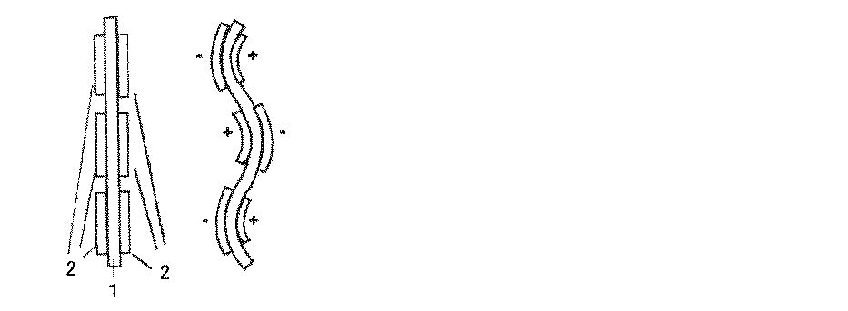
なお、電解質膜層表面への導電性薄膜層の形成は少なくとも2層必要であるが、図4に示すように、平面状の電解質膜層1の表面に多数の導電性薄膜層2を配置することにより、複雑な動きをさせることも可能である。このような素子により、蠕動運動による運搬や、マイクロマニピュレータなどを実現可能である。また、本発明のアクチュエータ素子の形状は、平面状とは限らず、任意の形状の素子が容易に製造可能である。例えば、図4に示すものは、径が1mm程度の電解質膜層1のロッドの周囲に4本の導電性薄膜層2を形成したものである。この素子により、細管内に挿入できるようなアクチュエータが実現可能である。
At least two conductive thin film layers are required to be formed on the surface of the electrolyte membrane layer. As shown in FIG. 4, a large number of conductive thin film layers 2 are arranged on the surface of the planar
以下、本発明を実施例に基づきより詳細に説明するが、本発明がこれら実施例に限定されないことは言うまでもない。 EXAMPLES Hereinafter, although this invention is demonstrated in detail based on an Example, it cannot be overemphasized that this invention is not limited to these Examples.
なお、本実施例において、アクチュエータ素子変位評価は、以下のようにして行った。 In this example, the actuator element displacement evaluation was performed as follows.
アクチュエータ素子変位評価法:図1(A)に示す様にレーザ変位計を用い、素子を1mmx10mmもしくは2mmx10mmの短冊状に切り取り、電圧を加えた時の固定端から5mmもしくは4mmの位置の変位を測定した。 Actuator element displacement evaluation method: Using a laser displacement meter as shown in Fig. 1 (A), cut the element into 1mmx10mm or 2mmx10mm strips and measure the displacement at 5mm or 4mm from the fixed end when voltage is applied. did.
実施例および比較例で用いたイオン液体(IL)は、エチルメチルイミダゾリウムテトラフルオロボレート(EMIBF4)である。The ionic liquid (IL) used in the examples and comparative examples is ethylmethylimidazolium tetrafluoroborate (EMIBF 4 ).
実施例および比較例で用いたカーボンナノチューブは、スーパーグロース・カーボンナノチューブ(SG、国立研究開発法人産業技術総合研究所製)である。 The carbon nanotubes used in Examples and Comparative Examples are super-growth carbon nanotubes (SG, manufactured by National Institute of Advanced Industrial Science and Technology).
実施例および比較例で用いたポリマーは、ポリフッ化ビニリデン−ヘキサフルオロプロピレン共重合体[PVDF(HFP);商品名kynar2801](V)である。 The polymer used in Examples and Comparative Examples is a polyvinylidene fluoride-hexafluoropropylene copolymer [PVDF (HFP); trade name kynar2801] (V).
実施例および比較例で用いた溶媒は、N,N’-ジメチルアセトアミド(DMAc)、プロピレンカーボネート(PC)、4−メチルペンタン−2−オン(MP)である。 The solvents used in Examples and Comparative Examples are N, N'-dimethylacetamide (DMAc), propylene carbonate (PC), and 4-methylpentan-2-one (MP).
実施例で用いたポリアニリン(PANI)は、アルドリッチ社製である。 The polyaniline (PANI) used in the examples is manufactured by Aldrich.
実施例で用いたカーボンナノホーン(CNH)は、商品名カーボンナノホーン(日本電気株式会社製)である。 The carbon nanohorn (CNH) used in the examples is a trade name carbon nanohorn (manufactured by NEC Corporation).
アクチュエータ性能指数は、変形量と発生力の積により求めた。 The actuator performance index was obtained from the product of the amount of deformation and the generated force.
アクチュエータ素子が変形する際に生じる発生力は、ロードセルにより直接測定した(図1(B))。
調製例1
[導電性薄膜層形成用分散液の調製]
DMAc溶媒中に、カーボンナノチューブ(SG−CNT)、ポリアニリン(PANI)、カーボンナノホーン(CNH)、イオン液体(IL)、ポリマー[粉末状PVDF(HFP)]を分散させて、マグネチックスターラーにて撹拌、その後、超音波による分散を行うことにより導電性薄膜層形成用分散液を調製する。The generated force generated when the actuator element deforms was directly measured by a load cell (FIG. 1 (B)).
Preparation Example 1
[Preparation of dispersion for forming conductive thin film layer]
Carbon nanotube (SG-CNT), polyaniline (PANI), carbon nanohorn (CNH), ionic liquid (IL), polymer [powdered PVDF (HFP)] are dispersed in DMAc solvent, and stirred with a magnetic stirrer. Thereafter, a dispersion for forming a conductive thin film layer is prepared by performing dispersion using ultrasonic waves.
具体的な量については、各実施例、各比較例に個別に示す。 Specific amounts are individually shown in each example and each comparative example.
[電解質膜形成用溶液の調製]
イオン液体(IL)とポリマー[粉末状PVDF(HFP)]を重量比で1:1の比率で混合し、上記導電性薄膜層形成用分散液の調製と同様にして、70℃で撹拌して溶媒に溶解させることにより、電解質膜形成用溶液を調製する。ここで溶媒は、4−メチルペンタン−2−オンとプロピレンカーボネートとの混合溶媒を用いた。[Preparation of electrolyte membrane forming solution]
An ionic liquid (IL) and a polymer [powdered PVDF (HFP)] are mixed at a weight ratio of 1: 1, and stirred at 70 ° C. in the same manner as in the preparation of the conductive thin film layer-forming dispersion. An electrolyte membrane forming solution is prepared by dissolving in a solvent. Here, a mixed solvent of 4-methylpentan-2-one and propylene carbonate was used as the solvent.
具体的な量については、各実施例、各比較例に個別に示す。 Specific amounts are individually shown in each example and each comparative example.
[アクチュエータ素子の製造]
導電性薄膜、電解質膜は、それぞれ上記のように調製した分散液および溶液を、別々に25mmx25mmのキャスト枠中にキャストし、室温で一昼夜溶媒を乾燥させ、次いで、真空乾燥を行うことにより得る。導電性薄膜2枚の間に、電解質膜を1枚挟んで熱圧着することにより3層構造のアクチュエータ素子を得る。アクチュエータ素子の厚みは、180μm〜550μm程度である。[Manufacture of actuator elements]
The conductive thin film and the electrolyte membrane are obtained by separately casting the dispersion and solution prepared as described above in a 25 mm × 25 mm cast frame, drying the solvent at room temperature overnight, and then performing vacuum drying. A three-layer actuator element is obtained by thermocompression bonding with one electrolyte membrane between two conductive thin films. The thickness of the actuator element is about 180 μm to 550 μm.
[アクチュエータ素子の評価方法]
製造したアクチュエータ素子の変位応答性の評価は、図1(A)に示した装置を用いて行った。アクチュエータ素子を、幅1mm×長さ10mm(図5、7、表1の場合)、もしくは、幅2mm×長さ10mm(図6の場合)の短冊状に切断し、端3mmの部分を電極付きホルダーでつかんで、空気中で電圧を加え、レーザ変位計を用いて、固定端から5mm(図5、7、表1の場合)もしくは4mm(図6の場合)の位置での変位を測定し、伸縮率(ε(%))は、アクチュエータの素子長(L(mm))、素子厚(W(mm))、変位(D(mm))から下記式により算出した:[Evaluation method of actuator element]
The displacement responsiveness of the manufactured actuator element was evaluated using the apparatus shown in FIG. The actuator element is cut into strips of
![]()
![]()
電圧の周波数を200Hz〜0.005Hzの範囲で変化させて調べた(図5A〜5D)。また、長時間のアクチュエータ素子のDC耐久性については、+2.0Vの一定電圧(DC)を印加し続けることにより評価した(図7、表1)。アクチュエータ素子が変形する際に生じる発生力はロードセルにより直接測定した(図1B)。 The voltage frequency was examined in the range of 200 Hz to 0.005 Hz (FIGS. 5A to 5D). Further, the DC durability of the actuator element for a long time was evaluated by continuing to apply a constant voltage (DC) of +2.0 V (FIG. 7, Table 1). The force generated when the actuator element deforms was directly measured by a load cell (FIG. 1B).
実施例1〜10及び比較例1〜2
実施例1
(SG-CNT/PANI/CNH)=(50/50/50)以下の比率で、カーボンナノチューブ(CNT)、ポリアニリン(PANI)、カーボンナノホーン(CNH)、ポリマー(kynar2801)及びイオン液体(EMIBF4)を使用して、導電性薄膜を得、上記の[アクチュエータ素子の製造]の記載に従い導電性薄膜層(電極)−電解質膜−導電性薄膜層(電極)からなる、3層構造のフィルム状のアクチュエータ素子を製造した。
電極:SG-CNT/PANI/CNH/kynar2801/EMIBF4=50.4mg/50.0mg/50.5mg/80.3mg/240.2mg
電解質:kynar2801/EMIBF4=200.3mg/200.3mgExamples 1-10 and Comparative Examples 1-2
Example 1
(SG-CNT / PANI / CNH) = (50/50/50) or less, carbon nanotube (CNT), polyaniline (PANI), carbon nanohorn (CNH), polymer (kynar2801) and ionic liquid (EMIBF 4 ) Is used to obtain a conductive thin film, which is composed of a conductive thin film layer (electrode) -electrolyte film-conductive thin film layer (electrode) in accordance with the description in [Manufacture of actuator element] above. An actuator element was manufactured.
Electrode: SG-CNT / PANI / CNH / kynar2801 / EMIBF 4 = 50.4mg / 50.0mg / 50.5mg / 80.3mg / 240.2mg
Electrolyte: kynar2801 / EMIBF 4 = 200.3mg / 200.3mg
実施例2
(SG-CNT/PANI/CNH)=(50/50/25)
以下の比率で、カーボンナノチューブ(CNT)、ポリアニリン(PANI)、カーボンナノホーン(CNH)、ポリマー(kynar2801)及びイオン液体(EMIBF4)を使用して導電性薄膜を得、上記の[アクチュエータ素子の製造]の記載に従い、導電性薄膜層(電極)−電解質膜−導電性薄膜層(電極)からなる、3層構造のフィルム状のアクチュエータ素子を製造した。
電極:SG-CNT/PANI/CNH/kynar2801/EMIBF4=50.5mg/50.3mg/25.1mg/80.1mg/240.5mg
電解質:kynar2801/EMIBF4=200.3mg/200.3mgExample 2
(SG-CNT / PANI / CNH) = (50/50/25)
Using the following ratios, carbon nanotubes (CNT), polyaniline (PANI), carbon nanohorns (CNH), polymer (kynar2801) and ionic liquid (EMIBF 4 ) are used to obtain a conductive thin film. ], A film-like actuator element having a three-layer structure comprising a conductive thin film layer (electrode) -electrolyte film-conductive thin film layer (electrode) was produced.
Electrode: SG-CNT / PANI / CNH / kynar2801 / EMIBF 4 = 50.5mg / 50.3mg / 25.1mg / 80.1mg / 240.5mg
Electrolyte: kynar2801 / EMIBF 4 = 200.3mg / 200.3mg
実施例3
(SG-CNT/PANI/CNH)=(50/25/50)
以下の比率で、カーボンナノチューブ(CNT)、ポリアニリン(PANI)、カーボンナノホーン(CNH)、ポリマー(kynar2801)及びイオン液体(EMIBF4)を使用して導電性薄膜を得、上記の[アクチュエータ素子の製造]の記載に従い、導電性薄膜層(電極)−電解質膜−導電性薄膜層(電極)からなる、3層構造のフィルム状のアクチュエータ素子を製造した。
電極:SG-CNT/PANI/CNH/kynar2801/EMIBF4=50.2mg/25.0mg/50.2mg/80.1mg/240.3mg
電解質:kynar2801/EMIBF4=200.3mg/200.3mgExample 3
(SG-CNT / PANI / CNH) = (50/25/50)
Using the following ratios, carbon nanotubes (CNT), polyaniline (PANI), carbon nanohorns (CNH), polymer (kynar2801) and ionic liquid (EMIBF 4 ) are used to obtain a conductive thin film. ], A film-like actuator element having a three-layer structure comprising a conductive thin film layer (electrode) -electrolyte film-conductive thin film layer (electrode) was produced.
Electrode: SG-CNT / PANI / CNH / kynar2801 / EMIBF 4 = 50.2mg / 25.0mg / 50.2mg / 80.1mg / 240.3mg
Electrolyte: kynar2801 / EMIBF 4 = 200.3mg / 200.3mg
実施例4
(SG-CNT/PANI/CNH)=(50/25/25)
以下の比率で、カーボンナノチューブ(CNT)、ポリアニリン(PANI)、カーボンナノホーン(CNH)、ポリマー(kynar2801)及びイオン液体(EMIBF4)を使用して導電性薄膜を得、上記の[アクチュエータ素子の製造]の記載に従い、導電性薄膜層(電極)−電解質膜−導電性薄膜層(電極)からなる、3層構造のフィルム状のアクチュエータ素子を製造した。
電極:SG-CNT/PANI/CNH/kynar2801/EMIBF4=50.0mg/25.0mg/25.1mg/80.5mg/240.5mg
電解質:kynar2801/EMIBF4=200.3mg/200.3mgExample 4
(SG-CNT / PANI / CNH) = (50/25/25)
Using the following ratios, carbon nanotubes (CNT), polyaniline (PANI), carbon nanohorns (CNH), polymer (kynar2801) and ionic liquid (EMIBF 4 ) are used to obtain a conductive thin film. ], A film-like actuator element having a three-layer structure comprising a conductive thin film layer (electrode) -electrolyte film-conductive thin film layer (electrode) was produced.
Electrode: SG-CNT / PANI / CNH / kynar2801 / EMIBF 4 = 50.0mg / 25.0mg / 25.1mg / 80.5mg / 240.5mg
Electrolyte: kynar2801 / EMIBF 4 = 200.3mg / 200.3mg
実施例5
(SG-CNT/PANI/CNH)=(25/50/50)
以下の比率で、カーボンナノチューブ(CNT)、ポリアニリン(PANI)、カーボンナノホーン(CNH)、ポリマー(kynar2801)及びイオン液体(EMIBF4)を使用して導電性薄膜を得、上記の[アクチュエータ素子の製造]の記載に従い、導電性薄膜層(電極)−電解質膜−導電性薄膜層(電極)からなる、3層構造のフィルム状のアクチュエータ素子を製造した。
電極:SG-CNT/PANI/CNH/kynar2801/EMIBF4=25.2mg/50.4mg/50.0mg/80.3mg/240.3mg
電解質:kynar2801/EMIBF4=200.3mg/200.3mgExample 5
(SG-CNT / PANI / CNH) = (25/50/50)
Using the following ratios, carbon nanotubes (CNT), polyaniline (PANI), carbon nanohorns (CNH), polymer (kynar2801) and ionic liquid (EMIBF 4 ) are used to obtain a conductive thin film. ], A film-like actuator element having a three-layer structure comprising a conductive thin film layer (electrode) -electrolyte film-conductive thin film layer (electrode) was produced.
Electrode: SG-CNT / PANI / CNH / kynar2801 / EMIBF 4 = 25.2mg / 50.4mg / 50.0mg / 80.3mg / 240.3mg
Electrolyte: kynar2801 / EMIBF 4 = 200.3mg / 200.3mg
実施例6
(SG-CNT/PANI/CNH)=(25/50/25)
以下の比率で、カーボンナノチューブ(CNT)、ポリアニリン(PANI)、カーボンナノホーン(CNH)、ポリマー(kynar2801)及びイオン液体(EMIBF4)を使用して導電性薄膜を得、上記の[アクチュエータ素子の製造]の記載に従い、導電性薄膜層(電極)−電解質膜−導電性薄膜層(電極)からなる、3層構造のフィルム状のアクチュエータ素子を製造した。
電極:SG-CNT/PANI/CNH/kynar2801/EMIBF4=25.1mg/50.0mg/25.0mg/80.5mg/240.4mg
電解質:kynar2801/EMIBF4=200.3mg/200.3mgExample 6
(SG-CNT / PANI / CNH) = (25/50/25)
Using the following ratios, carbon nanotubes (CNT), polyaniline (PANI), carbon nanohorns (CNH), polymer (kynar2801) and ionic liquid (EMIBF 4 ) are used to obtain a conductive thin film. ], A film-like actuator element having a three-layer structure comprising a conductive thin film layer (electrode) -electrolyte film-conductive thin film layer (electrode) was produced.
Electrode: SG-CNT / PANI / CNH / kynar2801 / EMIBF 4 = 25.1mg / 50.0mg / 25.0mg / 80.5mg / 240.4mg
Electrolyte: kynar2801 / EMIBF 4 = 200.3mg / 200.3mg
実施例7
(SG-CNT/PANI/CNH)=(25/25/50)
以下の比率で、カーボンナノチューブ(CNT)、ポリアニリン(PANI)、カーボンナノホーン(CNH)、ポリマー(kynar2801)及びイオン液体(EMIBF4)を使用して導電性薄膜を得、上記の[アクチュエータ素子の製造]の記載に従い、導電性薄膜層(電極)−電解質膜−導電性薄膜層(電極)からなる、3層構造のフィルム状のアクチュエータ素子を製造した。
電極:SG-CNT/PANI/CNH/kynar2801/EMIBF4=25.1mg/25.2mg/50.5mg/80.2mg/240.1mg
電解質:kynar2801/EMIBF4=200.3mg/200.3mgExample 7
(SG-CNT / PANI / CNH) = (25/25/50)
Using the following ratios, carbon nanotubes (CNT), polyaniline (PANI), carbon nanohorns (CNH), polymer (kynar2801) and ionic liquid (EMIBF 4 ) are used to obtain a conductive thin film. ], A film-like actuator element having a three-layer structure comprising a conductive thin film layer (electrode) -electrolyte film-conductive thin film layer (electrode) was produced.
Electrode: SG-CNT / PANI / CNH / kynar2801 / EMIBF 4 = 25.1mg / 25.2mg / 50.5mg / 80.2mg / 240.1mg
Electrolyte: kynar2801 / EMIBF 4 = 200.3mg / 200.3mg
実施例8
(SG-CNT/PANI/CNH)=(25/25/25)
以下の比率で、カーボンナノチューブ(CNT)、ポリアニリン(PANI)、カーボンナノホーン(CNH)、ポリマー(kynar2801)及びイオン液体(EMIBF4)を使用して導電性薄膜を得、上記の[アクチュエータ素子の製造]の記載に従い、導電性薄膜層(電極)−電解質膜−導電性薄膜層(電極)からなる、3層構造のフィルム状のアクチュエータ素子を製造した。
電極:SG-CNT/PANI/CNH/kynar2801/EMIBF4=25.4mg/25.1mg/25.2mg/80.4mg/240.0mg
電解質:kynar2801/EMIBF4=200.3mg/200.3mgExample 8
(SG-CNT / PANI / CNH) = (25/25/25)
Using the following ratios, carbon nanotubes (CNT), polyaniline (PANI), carbon nanohorns (CNH), polymer (kynar2801) and ionic liquid (EMIBF 4 ) are used to obtain a conductive thin film. ], A film-like actuator element having a three-layer structure comprising a conductive thin film layer (electrode) -electrolyte film-conductive thin film layer (electrode) was produced.
Electrode: SG-CNT / PANI / CNH / kynar2801 / EMIBF 4 = 25.4mg / 25.1mg / 25.2mg / 80.4mg / 240.0mg
Electrolyte: kynar2801 / EMIBF 4 = 200.3mg / 200.3mg
実施例9
(SG-CNT/PANI/CNH)=(12.5/50/50)
以下の比率で、カーボンナノチューブ(CNT)、ポリアニリン(PANI)、カーボンナノホーン(CNH)、ポリマー(kynar2801)及びイオン液体(EMIBF4)を使用して導電性薄膜を得、上記の[アクチュエータ素子の製造]の記載に従い、導電性薄膜層(電極)−電解質膜−導電性薄膜層(電極)からなる、3層構造のフィルム状のアクチュエータ素子を製造した。
電極:SG-CNT/PANI/CNH/kynar2801/EMIBF4=12.7mg/50.4mg/50.2mg/80.4mg/240.1mg
電解質:kynar2801/EMIBF4=200.3mg/200.3mgExample 9
(SG-CNT / PANI / CNH) = (12.5 / 50/50)
Using the following ratios, carbon nanotubes (CNT), polyaniline (PANI), carbon nanohorns (CNH), polymer (kynar2801) and ionic liquid (EMIBF 4 ) are used to obtain a conductive thin film. ], A film-like actuator element having a three-layer structure comprising a conductive thin film layer (electrode) -electrolyte film-conductive thin film layer (electrode) was produced.
Electrode: SG-CNT / PANI / CNH / kynar2801 / EMIBF 4 = 12.7mg / 50.4mg / 50.2mg / 80.4mg / 240.1mg
Electrolyte: kynar2801 / EMIBF 4 = 200.3mg / 200.3mg
実施例10
(SG-CNT/PANI/CNH)=(6.25/50/50)
以下の比率で、カーボンナノチューブ(CNT)、ポリアニリン(PANI)、カーボンナノホーン(CNH)、ポリマー(kynar2801)及びイオン液体(EMIBF4)を使用して導電性薄膜を得、上記の[アクチュエータ素子の製造]の記載に従い、導電性薄膜層(電極)−電解質膜−導電性薄膜層(電極)からなる、3層構造のフィルム状のアクチュエータ素子を製造した。
電極:SG-CNT/PANI/CNH/kynar2801/EMIBF4=6.3mg/50.1mg/50.1mg/80.1mg/240.1mg
電解質:kynar2801/EMIBF4=200.3mg/200.3mgExample 10
(SG-CNT / PANI / CNH) = (6.25 / 50/50)
Using the following ratios, carbon nanotubes (CNT), polyaniline (PANI), carbon nanohorns (CNH), polymer (kynar2801) and ionic liquid (EMIBF 4 ) are used to obtain a conductive thin film. ], A film-like actuator element having a three-layer structure comprising a conductive thin film layer (electrode) -electrolyte film-conductive thin film layer (electrode) was produced.
Electrode: SG-CNT / PANI / CNH / kynar2801 / EMIBF 4 = 6.3mg / 50.1mg / 50.1mg / 80.1mg / 240.1mg
Electrolyte: kynar2801 / EMIBF 4 = 200.3mg / 200.3mg
比較例1
(SG-CNT/PANI/CNH)=(50/50/0)
以下の比率で、カーボンナノチューブ(CNT)、ポリアニリン(PANI)、ポリマー(kynar2801)及びイオン液体(EMIBF4)を使用して導電性薄膜を得、上記の[アクチュエータ素子の製造]の記載に従い、導電性薄膜層(電極)−電解質膜−導電性薄膜層(電極)からなる、3層構造のフィルム状のアクチュエータ素子を製造した。
電極:SG-CNT/PANI/CNH/kynar2801/EMIBF4=50.4mg/50.0mg/0.0mg/80.0mg/240.4mg
電解質:kynar2801/EMIBF4=200.3mg/200.3mgComparative Example 1
(SG-CNT / PANI / CNH) = (50/50/0)
Using the following ratio, carbon nanotubes (CNT), polyaniline (PANI), polymer (kynar2801) and ionic liquid (EMIBF 4 ) are used to obtain a conductive thin film. A film-like actuator element having a three-layer structure comprising a conductive thin film layer (electrode) -electrolyte film-conductive thin film layer (electrode) was produced.
Electrode: SG-CNT / PANI / CNH / kynar2801 / EMIBF 4 = 50.4mg / 50.0mg / 0.0mg / 80.0mg / 240.4mg
Electrolyte: kynar2801 / EMIBF 4 = 200.3mg / 200.3mg
比較例2
(SG-CNT/PANI/CNH)=(50/0/50)
以下の比率で、カーボンナノチューブ(CNT)、カーボンナノホーン(CNH)、ポリマー(kynar2801)及びイオン液体(EMIBF4)を使用して導電性薄膜を得、上記の[アクチュエータ素子の製造]の記載に従い、導電性薄膜層(電極)−電解質膜−導電性薄膜層(電極)からなる、3層構造のフィルム状のアクチュエータ素子を製造した。
電極:SG-CNT/PANI/CNH/kynar2801/EMIBF4=50.4mg/0.0mg/50.0mg/80.3mg/240.2mg
電解質:kynar2801/EMIBF4=200.3mg/200.3mgComparative Example 2
(SG-CNT / PANI / CNH) = (50/0/50)
Using the following ratio, carbon nanotube (CNT), carbon nanohorn (CNH), polymer (kynar2801) and ionic liquid (EMIBF 4 ) are used to obtain a conductive thin film. According to the description of [Manufacture of actuator element] above, A film-like actuator element having a three-layer structure composed of a conductive thin film layer (electrode) -electrolyte film-conductive thin film layer (electrode) was produced.
Electrode: SG-CNT / PANI / CNH / kynar2801 / EMIBF 4 = 50.4mg / 0.0mg / 50.0mg / 80.3mg / 240.2mg
Electrolyte: kynar2801 / EMIBF 4 = 200.3mg / 200.3mg
以下の表1に記載の比率で、カーボンナノチューブ(SG−CNT)、ポリアニリン(PANI)、カーボンナノホーン(CNH)、イオン液体(EMIBF4)、ポリマー(PVDF(HFP);kynar2801)を使用して、導電性薄膜層(電極)−電解質膜−導電性薄膜層(電極)からなる、3層構造のフィルム状のアクチュエータ素子を製造し、DC(直流)電圧を長時間アクチュエータ素子に印加し続けた際の変位(伸縮率)の変化を図7に示した。また、図7から、各アクチュエータ素子の1800秒後の伸縮率と最大伸縮率の比により、DC電圧に対する耐久性(最大変位からの変形のずれ)を評価した(表1)。表1でA値が大きいもの程、耐久性は良い。Using carbon nanotubes (SG-CNT), polyaniline (PANI), carbon nanohorn (CNH), ionic liquid (EMIBF 4 ), polymer (PVDF (HFP); kynar2801) at the ratios shown in Table 1 below, When a three-layer film-like actuator element consisting of a conductive thin film layer (electrode) -electrolyte film-conductive thin film layer (electrode) is manufactured and a DC (direct current) voltage is continuously applied to the actuator element for a long time FIG. 7 shows the change in the displacement (expansion / contraction ratio). Further, from FIG. 7, the durability against DC voltage (deformation from the maximum displacement) was evaluated by the ratio of the expansion ratio after 1800 seconds and the maximum expansion ratio of each actuator element (Table 1). The higher the A value in Table 1, the better the durability.
A値=(1800秒後の伸縮率/最大伸縮率)×100 A value = (Expansion rate after 1800 seconds / Maximum expansion rate) x 100
図5及び図6から、以下のことが明らかになった。
(I)CNTが50(50mg)の場合、PANIおよびCNHの同時添加により、より周波数の遅い領域で変形が改善すること(図5B(50/X/X)の丸部分より)、
(II)CNTが25(25mg)の場合、PANI量よりCNHの添加量が多い方が変形および発生力とも改善されること(図5A,Cおよび図6の実施例6と7の比較より)、
(III)PANIおよびCNHの添加量を固定してCNT量を変化させると((X/50/50)の場合)CNTを少なくすることにより、変形および発生力の両方を改善できることが明らかになった(図5D(X/50/50)の丸部分および図6の実施例5,9,10の比較より)。From FIG. 5 and FIG. 6, the following became clear.
(I) When CNT is 50 (50 mg), deformation is improved in the slower frequency region by simultaneous addition of PANI and CNH (from the circle in Fig. 5B (50 / X / X)),
(II) When CNT is 25 (25 mg), the amount of CNH added is larger than the amount of PANI, and both deformation and generation force are improved (from comparison of FIGS. 5A and C and Examples 6 and 7 in FIG. 6). ,
(III) It is clear that both deformation and generation force can be improved by reducing the amount of CNT by changing the amount of CNT while fixing the addition amount of PANI and CNH (in the case of (X / 50/50)). (Compared with the round part in FIG. 5D (X / 50/50) and Examples 5, 9, and 10 in FIG. 6).
なお、実施例8(25/25/25)のアクチュエータは、比較例1,2に対して0.1Hzより速い周波数域では伸縮率が良い結果となっている。また、図7および表1より、以下のことが明らかになった。
(i)変位の戻り現象(最大変位から時間の経過とともに変位が減少する現象)は PANIに比べ、CNHの添加量を多くした方が改善できること、
(ii)PANIおよびCNHの添加量を固定してCNT量を変化させると((X/50/50)の場合)CNT量が多いほど変位の戻り現象が改善できること
が明らかになり、CNTにPANIおよびCNHを任意の量で添加することによりアクチュエータ素子のDC電圧に対する耐久性が改善可能となった。The actuator of Example 8 (25/25/25) has a good expansion / contraction rate in the frequency range faster than 0.1 Hz compared to Comparative Examples 1 and 2. Further, from FIG. 7 and Table 1, the following became clear.
(i) The return phenomenon of the displacement (a phenomenon in which the displacement decreases with the passage of time from the maximum displacement) can be improved by increasing the amount of CNH added compared to PANI.
(ii) When the amount of CNT is changed with the addition amount of PANI and CNH fixed (in the case of (X / 50/50)), it becomes clear that the return phenomenon of displacement can be improved as the amount of CNT increases. In addition, the durability against the DC voltage of the actuator element can be improved by adding any amount of CNH and CNH.
試験例1
実施例1〜10および比較例1〜2で得られたアクチュエータ素子の電圧に対する応答性の評価を、上述したアクチュエータ素子の評価方法により行い、伸縮率、アクチュエータ性能指数、DC電圧耐久性を調べた。得られた結果を、図5〜図7および表1に示す。Test example 1
The responsiveness to the voltage of the actuator elements obtained in Examples 1 to 10 and Comparative Examples 1 and 2 was evaluated by the above-described actuator element evaluation method, and the expansion ratio, actuator performance index, and DC voltage durability were examined. . The obtained results are shown in FIGS.
1 電解質膜
2 導電性薄膜層
3 導電層
4 イオン液体のカチオン
5 イオン液体のアニオンDESCRIPTION OF
Claims (7)
PANI/CNH=1/5〜3/1、
CNT/PANI=3/50〜3/1、
CNT/CNH=3/50〜3/1
である、請求項1に記載の導電性薄膜。 PANI / CNH = 1/5 to 3/1 in mass ratio,
CNT / PANI = 3/50 to 3/1,
CNT / CNH = 3 / 50-3 / 1
The conductive thin film according to claim 1, wherein
PANI/CNH=1/2〜2/1、
CNT/PANI=3/25〜2/1、
CNT/CNH=3/25〜2/1
である、請求項2に記載の導電性薄膜。 PANI / CNH = 1 / 2-2 / 1 by mass ratio,
CNT / PANI = 3/25 to 2/1
CNT / CNH = 3/25 to 2/1
The conductive thin film according to claim 2, wherein
Applications Claiming Priority (3)
| Application Number | Priority Date | Filing Date | Title |
|---|---|---|---|
| JP2015163328 | 2015-08-21 | ||
| JP2015163328 | 2015-08-21 | ||
| PCT/JP2016/074153 WO2017033836A1 (en) | 2015-08-21 | 2016-08-18 | Nanocarbon polymer actuator |
Publications (2)
| Publication Number | Publication Date |
|---|---|
| JPWO2017033836A1 JPWO2017033836A1 (en) | 2018-06-28 |
| JP6562319B2 true JP6562319B2 (en) | 2019-08-21 |
Family
ID=58100228
Family Applications (1)
| Application Number | Title | Priority Date | Filing Date |
|---|---|---|---|
| JP2017536390A Active JP6562319B2 (en) | 2015-08-21 | 2016-08-18 | Nanocarbon polymer actuator |
Country Status (4)
| Country | Link |
|---|---|
| US (1) | US20190010329A1 (en) |
| EP (1) | EP3340254A4 (en) |
| JP (1) | JP6562319B2 (en) |
| WO (1) | WO2017033836A1 (en) |
Families Citing this family (1)
| Publication number | Priority date | Publication date | Assignee | Title |
|---|---|---|---|---|
| CN112736186B (en) * | 2020-12-29 | 2022-09-02 | 合肥工业大学 | VO-based flexible mechanical claw 2 Double-layer flexible driver, preparation method and application |
Family Cites Families (4)
| Publication number | Priority date | Publication date | Assignee | Title |
|---|---|---|---|---|
| WO2009157491A1 (en) * | 2008-06-25 | 2009-12-30 | 独立行政法人産業技術総合研究所 | Actuator element utilizing carbon nanotube electrode with added auxiliary conducting agent |
| JP5252405B2 (en) * | 2008-09-12 | 2013-07-31 | アルプス電気株式会社 | Polymer actuator |
| JP2014024954A (en) * | 2012-07-26 | 2014-02-06 | National Institute Of Advanced Industrial & Technology | Actuator element including carbon electrode having clay material added thereto |
| WO2014104331A1 (en) * | 2012-12-27 | 2014-07-03 | アルプス電気株式会社 | Polymer actuator element |
-
2016
- 2016-08-18 EP EP16839183.7A patent/EP3340254A4/en not_active Withdrawn
- 2016-08-18 JP JP2017536390A patent/JP6562319B2/en active Active
- 2016-08-18 US US15/753,687 patent/US20190010329A1/en not_active Abandoned
- 2016-08-18 WO PCT/JP2016/074153 patent/WO2017033836A1/en active Application Filing
Also Published As
| Publication number | Publication date |
|---|---|
| EP3340254A4 (en) | 2019-04-10 |
| JPWO2017033836A1 (en) | 2018-06-28 |
| EP3340254A1 (en) | 2018-06-27 |
| US20190010329A1 (en) | 2019-01-10 |
| WO2017033836A1 (en) | 2017-03-02 |
Similar Documents
| Publication | Publication Date | Title |
|---|---|---|
| JP4873453B2 (en) | Conductive thin film, actuator element and manufacturing method thereof | |
| JP5083911B2 (en) | Actuator element composed of carbon nanotube, polymerizable ionic liquid and ionic liquid | |
| JP4038685B2 (en) | Actuator element | |
| JP5110574B2 (en) | High-aspect-ratio carbon nanotubes and ionic liquids, conductive thin films and actuator elements | |
| JP4568885B2 (en) | Actuator element using high-strength, high-conductivity thin film and manufacturing method thereof | |
| JP5046127B2 (en) | High-aspect-ratio carbon nanotubes and ionic liquids, conductive thin films and actuator elements | |
| JP5332027B2 (en) | Actuator element using carbon nanotube electrode with conductive additive | |
| JP6713693B2 (en) | Actuator element using carbon electrode | |
| JP6128508B2 (en) | Carbon nanofiber actuator | |
| JP5004078B2 (en) | Actuator element with highly oriented electrodes using high aspect ratio carbon nanotubes | |
| JP4691703B2 (en) | Actuator element and manufacturing method thereof | |
| JP6964855B2 (en) | Conductive thin film, laminate, actuator element and its manufacturing method | |
| JP5888666B2 (en) | Conductive thin film and actuator elements composed of multi-walled carbon nanotubes, polymer and ionic liquid | |
| JP2010158103A (en) | Actuator | |
| JP5477643B2 (en) | Electrode film composed of carbon nanotube, alkali metal salt and / or alkaline earth metal salt, ionic liquid and polymer, solid electrolyte film, actuator element | |
| JP6562319B2 (en) | Nanocarbon polymer actuator | |
| JP2014024954A (en) | Actuator element including carbon electrode having clay material added thereto | |
| JP6359248B2 (en) | Conductive thin film, laminate, actuator element, and manufacturing method thereof | |
| JP2012135071A (en) | Composite conductive thin film for actuator, and actuator element | |
| JP2012135074A (en) | Conductive thin film comprising carbon nanotube, polyvinylidene fluoride polymer and ionic liquid, and actuator element | |
| JP5665055B2 (en) | Actuator element driving method and manufacturing method |
Legal Events
| Date | Code | Title | Description |
|---|---|---|---|
| A621 | Written request for application examination |
Free format text: JAPANESE INTERMEDIATE CODE: A621 Effective date: 20180130 |
|
| A131 | Notification of reasons for refusal |
Free format text: JAPANESE INTERMEDIATE CODE: A131 Effective date: 20190402 |
|
| A601 | Written request for extension of time |
Free format text: JAPANESE INTERMEDIATE CODE: A601 Effective date: 20190529 |
|
| A521 | Request for written amendment filed |
Free format text: JAPANESE INTERMEDIATE CODE: A523 Effective date: 20190610 |
|
| TRDD | Decision of grant or rejection written | ||
| A01 | Written decision to grant a patent or to grant a registration (utility model) |
Free format text: JAPANESE INTERMEDIATE CODE: A01 Effective date: 20190710 |
|
| A61 | First payment of annual fees (during grant procedure) |
Free format text: JAPANESE INTERMEDIATE CODE: A61 Effective date: 20190711 |
|
| R150 | Certificate of patent or registration of utility model |
Ref document number: 6562319 Country of ref document: JP Free format text: JAPANESE INTERMEDIATE CODE: R150 |
|
| R250 | Receipt of annual fees |
Free format text: JAPANESE INTERMEDIATE CODE: R250 |
|
| R250 | Receipt of annual fees |
Free format text: JAPANESE INTERMEDIATE CODE: R250 |