JP6562015B2 - Power system - Google Patents
Power system Download PDFInfo
- Publication number
- JP6562015B2 JP6562015B2 JP2017030442A JP2017030442A JP6562015B2 JP 6562015 B2 JP6562015 B2 JP 6562015B2 JP 2017030442 A JP2017030442 A JP 2017030442A JP 2017030442 A JP2017030442 A JP 2017030442A JP 6562015 B2 JP6562015 B2 JP 6562015B2
- Authority
- JP
- Japan
- Prior art keywords
- battery
- soc
- lithium ion
- ion battery
- power supply
- Prior art date
- Legal status (The legal status is an assumption and is not a legal conclusion. Google has not performed a legal analysis and makes no representation as to the accuracy of the status listed.)
- Active
Links
- HBBGRARXTFLTSG-UHFFFAOYSA-N Lithium ion Chemical group [Li+] HBBGRARXTFLTSG-UHFFFAOYSA-N 0.000 claims description 123
- 229910001416 lithium ion Inorganic materials 0.000 claims description 123
- 238000000034 method Methods 0.000 claims description 75
- 238000007599 discharging Methods 0.000 claims description 4
- 238000012544 monitoring process Methods 0.000 description 50
- 230000010287 polarization Effects 0.000 description 21
- 230000008030 elimination Effects 0.000 description 14
- 238000003379 elimination reaction Methods 0.000 description 14
- 238000010248 power generation Methods 0.000 description 14
- 238000012545 processing Methods 0.000 description 14
- 238000010586 diagram Methods 0.000 description 9
- 230000009977 dual effect Effects 0.000 description 6
- 230000007423 decrease Effects 0.000 description 4
- 230000001133 acceleration Effects 0.000 description 3
- 238000012360 testing method Methods 0.000 description 3
- 238000012986 modification Methods 0.000 description 2
- 230000004048 modification Effects 0.000 description 2
- 230000005540 biological transmission Effects 0.000 description 1
- 238000004891 communication Methods 0.000 description 1
- 230000003247 decreasing effect Effects 0.000 description 1
- 230000010354 integration Effects 0.000 description 1
- 230000028161 membrane depolarization Effects 0.000 description 1
- 230000001172 regenerating effect Effects 0.000 description 1
- 239000007858 starting material Substances 0.000 description 1
Images


Classifications
-
- H—ELECTRICITY
- H02—GENERATION; CONVERSION OR DISTRIBUTION OF ELECTRIC POWER
- H02J—CIRCUIT ARRANGEMENTS OR SYSTEMS FOR SUPPLYING OR DISTRIBUTING ELECTRIC POWER; SYSTEMS FOR STORING ELECTRIC ENERGY
- H02J7/00—Circuit arrangements for charging or depolarising batteries or for supplying loads from batteries
- H02J7/34—Parallel operation in networks using both storage and other dc sources, e.g. providing buffering
-
- B—PERFORMING OPERATIONS; TRANSPORTING
- B60—VEHICLES IN GENERAL
- B60L—PROPULSION OF ELECTRICALLY-PROPELLED VEHICLES; SUPPLYING ELECTRIC POWER FOR AUXILIARY EQUIPMENT OF ELECTRICALLY-PROPELLED VEHICLES; ELECTRODYNAMIC BRAKE SYSTEMS FOR VEHICLES IN GENERAL; MAGNETIC SUSPENSION OR LEVITATION FOR VEHICLES; MONITORING OPERATING VARIABLES OF ELECTRICALLY-PROPELLED VEHICLES; ELECTRIC SAFETY DEVICES FOR ELECTRICALLY-PROPELLED VEHICLES
- B60L58/00—Methods or circuit arrangements for monitoring or controlling batteries or fuel cells, specially adapted for electric vehicles
- B60L58/10—Methods or circuit arrangements for monitoring or controlling batteries or fuel cells, specially adapted for electric vehicles for monitoring or controlling batteries
- B60L58/12—Methods or circuit arrangements for monitoring or controlling batteries or fuel cells, specially adapted for electric vehicles for monitoring or controlling batteries responding to state of charge [SoC]
-
- B—PERFORMING OPERATIONS; TRANSPORTING
- B60—VEHICLES IN GENERAL
- B60L—PROPULSION OF ELECTRICALLY-PROPELLED VEHICLES; SUPPLYING ELECTRIC POWER FOR AUXILIARY EQUIPMENT OF ELECTRICALLY-PROPELLED VEHICLES; ELECTRODYNAMIC BRAKE SYSTEMS FOR VEHICLES IN GENERAL; MAGNETIC SUSPENSION OR LEVITATION FOR VEHICLES; MONITORING OPERATING VARIABLES OF ELECTRICALLY-PROPELLED VEHICLES; ELECTRIC SAFETY DEVICES FOR ELECTRICALLY-PROPELLED VEHICLES
- B60L58/00—Methods or circuit arrangements for monitoring or controlling batteries or fuel cells, specially adapted for electric vehicles
- B60L58/10—Methods or circuit arrangements for monitoring or controlling batteries or fuel cells, specially adapted for electric vehicles for monitoring or controlling batteries
- B60L58/18—Methods or circuit arrangements for monitoring or controlling batteries or fuel cells, specially adapted for electric vehicles for monitoring or controlling batteries of two or more battery modules
- B60L58/20—Methods or circuit arrangements for monitoring or controlling batteries or fuel cells, specially adapted for electric vehicles for monitoring or controlling batteries of two or more battery modules having different nominal voltages
-
- G—PHYSICS
- G01—MEASURING; TESTING
- G01R—MEASURING ELECTRIC VARIABLES; MEASURING MAGNETIC VARIABLES
- G01R31/00—Arrangements for testing electric properties; Arrangements for locating electric faults; Arrangements for electrical testing characterised by what is being tested not provided for elsewhere
- G01R31/36—Arrangements for testing, measuring or monitoring the electrical condition of accumulators or electric batteries, e.g. capacity or state of charge [SoC]
- G01R31/382—Arrangements for monitoring battery or accumulator variables, e.g. SoC
- G01R31/3842—Arrangements for monitoring battery or accumulator variables, e.g. SoC combining voltage and current measurements
-
- H—ELECTRICITY
- H02—GENERATION; CONVERSION OR DISTRIBUTION OF ELECTRIC POWER
- H02J—CIRCUIT ARRANGEMENTS OR SYSTEMS FOR SUPPLYING OR DISTRIBUTING ELECTRIC POWER; SYSTEMS FOR STORING ELECTRIC ENERGY
- H02J7/00—Circuit arrangements for charging or depolarising batteries or for supplying loads from batteries
- H02J7/0013—Circuit arrangements for charging or depolarising batteries or for supplying loads from batteries acting upon several batteries simultaneously or sequentially
- H02J7/0014—Circuits for equalisation of charge between batteries
- H02J7/0016—Circuits for equalisation of charge between batteries using shunting, discharge or bypass circuits
-
- H02J7/0022—
-
- H02J7/0026—
-
- H—ELECTRICITY
- H02—GENERATION; CONVERSION OR DISTRIBUTION OF ELECTRIC POWER
- H02J—CIRCUIT ARRANGEMENTS OR SYSTEMS FOR SUPPLYING OR DISTRIBUTING ELECTRIC POWER; SYSTEMS FOR STORING ELECTRIC ENERGY
- H02J7/00—Circuit arrangements for charging or depolarising batteries or for supplying loads from batteries
- H02J7/14—Circuit arrangements for charging or depolarising batteries or for supplying loads from batteries for charging batteries from dynamo-electric generators driven at varying speed, e.g. on vehicle
- H02J7/1423—Circuit arrangements for charging or depolarising batteries or for supplying loads from batteries for charging batteries from dynamo-electric generators driven at varying speed, e.g. on vehicle with multiple batteries
-
- B—PERFORMING OPERATIONS; TRANSPORTING
- B60—VEHICLES IN GENERAL
- B60L—PROPULSION OF ELECTRICALLY-PROPELLED VEHICLES; SUPPLYING ELECTRIC POWER FOR AUXILIARY EQUIPMENT OF ELECTRICALLY-PROPELLED VEHICLES; ELECTRODYNAMIC BRAKE SYSTEMS FOR VEHICLES IN GENERAL; MAGNETIC SUSPENSION OR LEVITATION FOR VEHICLES; MONITORING OPERATING VARIABLES OF ELECTRICALLY-PROPELLED VEHICLES; ELECTRIC SAFETY DEVICES FOR ELECTRICALLY-PROPELLED VEHICLES
- B60L2240/00—Control parameters of input or output; Target parameters
- B60L2240/40—Drive Train control parameters
- B60L2240/54—Drive Train control parameters related to batteries
- B60L2240/547—Voltage
-
- G—PHYSICS
- G01—MEASURING; TESTING
- G01R—MEASURING ELECTRIC VARIABLES; MEASURING MAGNETIC VARIABLES
- G01R31/00—Arrangements for testing electric properties; Arrangements for locating electric faults; Arrangements for electrical testing characterised by what is being tested not provided for elsewhere
- G01R31/36—Arrangements for testing, measuring or monitoring the electrical condition of accumulators or electric batteries, e.g. capacity or state of charge [SoC]
- G01R31/382—Arrangements for monitoring battery or accumulator variables, e.g. SoC
- G01R31/3828—Arrangements for monitoring battery or accumulator variables, e.g. SoC using current integration
-
- H—ELECTRICITY
- H02—GENERATION; CONVERSION OR DISTRIBUTION OF ELECTRIC POWER
- H02J—CIRCUIT ARRANGEMENTS OR SYSTEMS FOR SUPPLYING OR DISTRIBUTING ELECTRIC POWER; SYSTEMS FOR STORING ELECTRIC ENERGY
- H02J2310/00—The network for supplying or distributing electric power characterised by its spatial reach or by the load
- H02J2310/40—The network being an on-board power network, i.e. within a vehicle
-
- H—ELECTRICITY
- H02—GENERATION; CONVERSION OR DISTRIBUTION OF ELECTRIC POWER
- H02J—CIRCUIT ARRANGEMENTS OR SYSTEMS FOR SUPPLYING OR DISTRIBUTING ELECTRIC POWER; SYSTEMS FOR STORING ELECTRIC ENERGY
- H02J7/00—Circuit arrangements for charging or depolarising batteries or for supplying loads from batteries
- H02J7/14—Circuit arrangements for charging or depolarising batteries or for supplying loads from batteries for charging batteries from dynamo-electric generators driven at varying speed, e.g. on vehicle
- H02J7/143—Circuit arrangements for charging or depolarising batteries or for supplying loads from batteries for charging batteries from dynamo-electric generators driven at varying speed, e.g. on vehicle with multiple generators
-
- Y—GENERAL TAGGING OF NEW TECHNOLOGICAL DEVELOPMENTS; GENERAL TAGGING OF CROSS-SECTIONAL TECHNOLOGIES SPANNING OVER SEVERAL SECTIONS OF THE IPC; TECHNICAL SUBJECTS COVERED BY FORMER USPC CROSS-REFERENCE ART COLLECTIONS [XRACs] AND DIGESTS
- Y02—TECHNOLOGIES OR APPLICATIONS FOR MITIGATION OR ADAPTATION AGAINST CLIMATE CHANGE
- Y02T—CLIMATE CHANGE MITIGATION TECHNOLOGIES RELATED TO TRANSPORTATION
- Y02T10/00—Road transport of goods or passengers
- Y02T10/60—Other road transportation technologies with climate change mitigation effect
- Y02T10/70—Energy storage systems for electromobility, e.g. batteries
Landscapes
- Engineering & Computer Science (AREA)
- Power Engineering (AREA)
- Life Sciences & Earth Sciences (AREA)
- Sustainable Development (AREA)
- Sustainable Energy (AREA)
- Transportation (AREA)
- Mechanical Engineering (AREA)
- Physics & Mathematics (AREA)
- General Physics & Mathematics (AREA)
- Charge And Discharge Circuits For Batteries Or The Like (AREA)
- Secondary Cells (AREA)
Description
本開示は、電源システムに関する。 The present disclosure relates to a power supply system.
イグニッションスイッチのオフ時にリチウムイオンバッテリを電源回路から電気的に切り離し、一定時間後に(リチウムイオンバッテリの分極が解消してから)リチウムイオンバッテリの開放電圧(Open-circuit voltage)を取得することで、リチウムイオンバッテリのSOC(State Of Charge)の算出精度を高める技術が知られている(例えば、特許文献1参照)。 By electrically disconnecting the lithium-ion battery from the power supply circuit when the ignition switch is off and acquiring the open-circuit voltage of the lithium-ion battery after a certain period of time (after the polarization of the lithium-ion battery disappears) A technique for improving the calculation accuracy of SOC (State Of Charge) of a lithium ion battery is known (see, for example, Patent Document 1).
しかしながら、イグニッションスイッチのオン時から時間が経過した後は、リチウムイオンバッテリの開放電圧を取得することが難しいため、リチウムイオンバッテリのSOCを補正することが難しい。イグニッションスイッチのオン時からは、リチウムイオンバッテリのSOCは、イグニッションスイッチのオン時からのリチウムイオンバッテリの充電電流と放電電流の積算値である積算電流値に基づいて更新できるが、積算電流値が大きくなるにつれてSOCの誤差が大きくなる虞がある。 However, after a lapse of time from when the ignition switch is turned on, it is difficult to obtain the open voltage of the lithium ion battery, so it is difficult to correct the SOC of the lithium ion battery. From the time when the ignition switch is turned on, the SOC of the lithium ion battery can be updated based on the accumulated current value that is the accumulated value of the charging current and discharge current of the lithium ion battery from when the ignition switch is turned on. There is a risk that the SOC error increases as the value increases.
そこで、一側面によれば、本発明は、イグニッションスイッチのオン時から時間が経過した後に、リチウムイオンバッテリの開放電圧を取得可能とする。 Therefore, according to one aspect, the present invention makes it possible to acquire the open-circuit voltage of a lithium ion battery after a lapse of time from when the ignition switch is turned on.
本発明の一態様によれば、電源回路に設けられる第1バッテリと、
前記電源回路に設けられる第2バッテリであり、前記第1バッテリに並列に電気的に接続され、リチウムイオンバッテリである第2バッテリと、
前記電源回路に設けられ、前記第1バッテリ及び前記第2バッテリに並列に電気的に接続された電気負荷と、
前記電源回路に設けられ、開状態のときは前記第2バッテリを前記電源回路から電気的に切り離すスイッチと、
イグニッションスイッチがオン状態でありかつ前記第1バッテリのSOCが所定のSOC以上である状態において、前記スイッチを開き、前記スイッチを開いてから所定時間経過した後に、前記第2バッテリの開放電圧を取得する開放電圧取得処理を行うように構成された制御装置とを含む、電源システムが提供される。
According to one aspect of the present invention, a first battery provided in a power supply circuit;
A second battery provided in the power supply circuit, electrically connected in parallel to the first battery, and a second battery that is a lithium ion battery;
An electrical load provided in the power supply circuit and electrically connected in parallel to the first battery and the second battery;
A switch provided in the power supply circuit to electrically disconnect the second battery from the power supply circuit when in an open state;
When the ignition switch is on and the SOC of the first battery is greater than or equal to a predetermined SOC, the switch is opened, and after a predetermined time has elapsed since the switch was opened, the open voltage of the second battery is acquired. There is provided a power supply system including a control device configured to perform an open circuit voltage acquisition process.
上記の態様によれば、イグニッションスイッチのオン状態(イグニッションスイッチのオン時から時間が経過した後)において、リチウムイオンバッテリの開放電圧を取得可能となる。また、第1バッテリのSOCが所定のSOC以上である状態において、スイッチが開かれるので、スイッチが開かれることに起因した不都合、即ちリチウムイオンバッテリが電源回路から電気的に切り離されることで第1バッテリのSOCが比較的に急に低下して下限値を下回ってしまう虞、を低減できる。 According to the above aspect, the open-circuit voltage of the lithium ion battery can be acquired when the ignition switch is on (after the time has elapsed since the ignition switch was turned on). In addition, since the switch is opened in a state where the SOC of the first battery is equal to or higher than the predetermined SOC, the first problem is that the lithium ion battery is electrically disconnected from the power supply circuit due to the inconvenience caused by the opening of the switch. It is possible to reduce the risk that the SOC of the battery will drop relatively rapidly and fall below the lower limit.
上記の態様において、前記制御装置は、前記開放電圧取得処理により取得した前記開放電圧に基づいて、前記第2バッテリのSOCを算出するSOC算出処理を更に行うように構成されてもよい。これにより、イグニッションスイッチのオン状態において、開放電圧取得処理により取得した開放電圧に基づく高精度の第2バッテリのSOCを得ることができる。 In the above aspect, the control device may be configured to further perform an SOC calculation process for calculating an SOC of the second battery based on the open circuit voltage acquired by the open circuit voltage acquisition process. Thereby, in the ON state of the ignition switch, it is possible to obtain a highly accurate SOC of the second battery based on the open circuit voltage acquired by the open circuit voltage acquisition process.
上記の態様において、前記制御装置は、前記第2バッテリの充電電流と放電電流の積算値である積算電流値が所定値以上となった場合に、前記開放電圧取得処理及び前記SOC算出処理を行うように構成されてもよい。これにより、第2バッテリのSOCの算出精度が低下した可能性が高いタイミングで、開放電圧に基づく高精度の第2バッテリのSOCを得ることができる。 In the above aspect, the control device performs the open-circuit voltage acquisition process and the SOC calculation process when an integrated current value that is an integrated value of the charging current and the discharging current of the second battery becomes equal to or greater than a predetermined value. It may be configured as follows. Thereby, the highly accurate SOC of the second battery based on the open circuit voltage can be obtained at a timing when the possibility that the calculation accuracy of the SOC of the second battery has decreased is high.
上記の態様において、前記制御装置は、前記第2バッテリの充電電流と放電電流の積算値である積算電流値が所定値以上となった際に、前記第1バッテリのSOCが前記所定のSOC以上でない場合は、前記第1バッテリのSOCが前記所定のSOC以上になるように前記第1バッテリを充電させる充電処理を更に行うように構成されてもよい。これにより、第2バッテリのSOCの算出精度が低下した可能性が高いタイミングで、第1バッテリのSOCが所定のSOC以上でない場合でも、第1バッテリのSOCを高めてから、開放電圧取得処理及びSOC算出処理を開始できる。 In the above aspect, when the integrated current value, which is the integrated value of the charging current and discharging current of the second battery, is equal to or greater than a predetermined value, the control device is configured such that the SOC of the first battery is equal to or greater than the predetermined SOC. Otherwise, it may be configured to further perform a charging process for charging the first battery so that the SOC of the first battery is equal to or higher than the predetermined SOC. Thereby, even when the SOC of the first battery is not equal to or higher than the predetermined SOC at a timing at which the calculation accuracy of the SOC of the second battery is likely to be reduced, the open-circuit voltage acquisition process and the The SOC calculation process can be started.
上記の態様において、前記電源回路に設けられ、前記第1バッテリ、前記第2バッテリ及び前記電気負荷に並列に電気的に接続されたオルタネータを更に含み、前記充電処理は、前記第2バッテリ及び前記オルタネータを用いて前記第1バッテリを充電することを含んでもよい。これにより、第2バッテリ及びオルタネータを用いて第1バッテリを速やかに充電できる。 In the above aspect, the power supply circuit further includes an alternator that is electrically connected in parallel to the first battery, the second battery, and the electric load, and the charging process includes the second battery and the Charging the first battery using an alternator may be included. Thereby, a 1st battery can be charged rapidly using a 2nd battery and an alternator.
一側面によれば、イグニッションスイッチのオン時から時間が経過した後に、リチウムイオンバッテリの開放電圧を取得可能となる。 According to one aspect, the open-circuit voltage of the lithium ion battery can be acquired after a lapse of time from when the ignition switch is turned on.
以下、添付図面を参照しながら各実施例について詳細に説明する。 Hereinafter, embodiments will be described in detail with reference to the accompanying drawings.
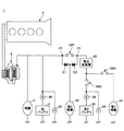
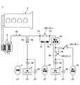
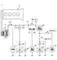
図1は、本実施例の2電源システム1の電気系を示す概略図である。
FIG. 1 is a schematic diagram showing an electrical system of a dual
2電源システム1は、図1に示すように電源回路に、鉛バッテリ4と、補機5(電気負荷の一例)と、オルタネータ6と、リチウムイオンバッテリ40と、第2補機50(電気負荷の一例)と、第3補機54(電気負荷の一例)と、電圧変換器60とを備える。
As shown in FIG. 1, the two-
鉛バッテリ4は、例えば定格電圧が12Vである。鉛バッテリ4に対しては、電流センサ80及び電圧センサ82が設けられる。電流センサ80は、鉛バッテリ4に流れる又は鉛バッテリ4から流れる電流を検出する。電圧センサ82は、鉛バッテリ4の電圧を検出する。
The lead battery 4 has a rated voltage of 12V, for example. A
補機5は、鉛バッテリ4から電力供給を受ける電気負荷を含む。補機5は、例えば、スタータ、ヒートシータ、ランプ、ブロア、ワイパ、電動ファン等を含む。 The auxiliary machine 5 includes an electric load that receives power supply from the lead battery 4. The auxiliary machine 5 includes, for example, a starter, a heat theta, a lamp, a blower, a wiper, and an electric fan.
オルタネータ6は、エンジン2に機械的に接続される。オルタネータ6は、エンジン2の動力を用いて発電を行う発電機である。オルタネータ6により生成される電力は鉛バッテリ4の充電や補機5の作動等に利用される。
The
リチウムイオンバッテリ40は、鉛バッテリ4よりも定格電圧が高く、例えば24V又は48Vを定格電圧とする。リチウムイオンバッテリ40は、鉛バッテリ4や、補機5、オルタネータ6等と並列に電気的に接続される。リチウムイオンバッテリ40に対しては、電流センサ83が及び電圧センサ84が設けられる。電流センサ83は、リチウムイオンバッテリ40に流れる又はリチウムイオンバッテリ40から流れる電流を検出する。電圧センサ84は、リチウムイオンバッテリ40の電圧を検出する。
The
第2補機50は、リチウムイオンバッテリ40から電力供給を受ける電気負荷を含む。第2補機50は、補機5とは異なる。第2補機50は、高い信頼性が要求される補機であることが望ましい。第2補機50は、例えば、シフトバイワイヤ(トランスミッションのアクチュエータ)や、EPB(エレクトリックパーキングブレーキ)、パワーステアリングのアシストモータ等であってよい。
Second
第2補機50は、第2補機50に向かう電流の流れを許容する向きに配置された第1ダイオードD1を介して、鉛バッテリ4及びオルタネータ6に電気的に接続される。また、第2補機50は、第2補機50に向かう電流の流れを許容する向きに配置された第2ダイオードD2を介して、リチウムイオンバッテリ40に電気的に接続される。
The second
第3補機54は、スイッチSW3を介して、リチウムイオンバッテリ40と電圧変換器60との間に電気的に接続される。第3補機54は、リチウムイオンバッテリ40や電圧変換器60の出力電圧(昇圧動作時の出力電圧)で動作する高圧系負荷である。
The third
電圧変換器60は、直流電圧で動作する電圧変換器であり、DC−DCコンバータとも称される。電圧変換器60は、昇圧動作時、鉛バッテリ4やオルタネータ6側の電圧を昇圧してリチウムイオンバッテリ40や第3補機54に印加する。従って、電圧変換器60の昇圧動作時は、リチウムイオンバッテリ40が充電される。また、電圧変換器60は、降圧動作時、リチウムイオンバッテリ40側の電圧を降圧して鉛バッテリ4や、補機5、第2補機50等に印加する。従って、電圧変換器60の降圧動作時は、リチウムイオンバッテリ40からの電流により鉛バッテリ4を充電することが可能である。
The
スイッチSW1は、オフ時(開時)に鉛バッテリ4、オルタネータ6、及び補機5から第2補機50及びリチウムイオンバッテリ40を電気的に切り離すことができる位置に設けられる。スイッチSW1は、第1ダイオードD1のアノード側のポイントP1と、第2ダイオードD2のアノード側のポイントP2との間に設けられる。スイッチSW1は、例えばリレーにより形成される。
The switch SW <b> 1 is provided at a position where the second
スイッチSW2は、オフ時(開時)に鉛バッテリ4、オルタネータ6、補機5、第2補機50、及び第3補機54からリチウムイオンバッテリ40を電気的に切り離すことができる位置に設けられる。スイッチSW2は、例えばリレーにより形成される。スイッチSW2は、基本的にオン状態とされる。スイッチSW2は、以下で説明するように、後述の開放電圧取得処理等を行う際にオフ状態とされる。
The switch SW2 is provided at a position where the
スイッチSW3は、オフ時(開時)に第3補機54をリチウムイオンバッテリ40及び電圧変換器60から電気的に切り離すことができる位置に設けられる。スイッチSW3は、例えばリレーにより形成される。スイッチSW3は、基本的にオン状態とされる。以下では、イグニッションスイッチのオン状態では、スイッチSW1及びスイッチSW3は、オン状態であるものとして、説明を続ける。
The switch SW3 is provided at a position where the third
図2は、2電源システム1の制御系の一例の概略的な構成図である。
FIG. 2 is a schematic configuration diagram of an example of a control system of the dual
2電源システム1は、電源制御装置30を含む。電源制御装置30は、コンピュータにより形成され、例えば、ECU(Electronic Control Unit)により実現される。電源制御装置30は、ハードウェア構成としては、図示しないが、CPU(Central Processing Unit)の他、RAM(Random Access Memory)や、ROM(Read Only Memory)、補助記憶装置のようなメモリ、通信インターフェース等を含む。電源制御装置30には、オルタネータ6、電圧変換器60、電流センサ80,83、電圧センサ82,84、及びスイッチSW2が接続される。
The dual
電源制御装置30は、リチウムイオンバッテリ状態監視部32と、発電機制御部34と、電圧変換器制御部36と、鉛バッテリ状態監視部38とを含む。尚、リチウムイオンバッテリ状態監視部32、発電機制御部34、電圧変換器制御部36、及び鉛バッテリ状態監視部38は、電源制御装置30のCPUがメモリ内のプログラムを実行することで実現できる。
The power
リチウムイオンバッテリ状態監視部32は、電流センサ83及び電圧センサ84からの情報に基づいて、所定周期毎に、リチウムイオンバッテリ40のSOCを算出する。リチウムイオンバッテリ40のSOCは、例えばイグニッションスイッチのオン時のリチウムイオンバッテリ40のSOCと、イグニッションスイッチのオン時からのリチウムイオンバッテリ40の充放電量積算値とに基づいて算出することができる。イグニッションスイッチのオン時のリチウムイオンバッテリ40のSOCは、スイッチSW2がオフ状態で電圧センサ84で検出された電圧値である開放電圧に基づいて導出される。一般的に知られているように、リチウムイオンバッテリのSOCと、分極状態でないときのリチウムイオンバッテリの開放電圧とは、高い相関がある。イグニッションスイッチのオフ状態では、リチウムイオンバッテリ40の充放電が実質的にないため、リチウムイオンバッテリ40の分極状態が解消している可能性が高い。従って、イグニッションスイッチのオン時の開放電圧を用いると、リチウムイオンバッテリ40のSOCを精度良く算出できる。
The lithium ion battery
また、リチウムイオンバッテリ状態監視部32は、開放電圧取得処理を行う。開放電圧取得処理は、イグニッションスイッチがオン状態でありかつ鉛バッテリ4のSOCが所定のSOC(以下、「分極解消可能SOC」と称する)以上である状態において、スイッチSW2をオフし、スイッチSW2をオフしてから所定時間(以下、「分極解消放電時間Ta」と称する)経過した後に、リチウムイオンバッテリ40の開放電圧を取得することを含む。開放電圧取得処理により、イグニッションスイッチのオン時から時間が経過した後に、リチウムイオンバッテリ40の開放電圧を取得することが可能となる。
Moreover, the lithium ion battery
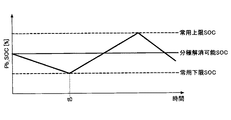
分極解消可能SOCは、鉛バッテリ4のSOCの所定の常用下限SOCに対して、所定の余裕値を増分した値である。所定の余裕値は、リチウムイオンバッテリ40を電気的に切り離した状態を分極解消放電時間Taだけ維持した場合に低下しうる鉛バッテリ4のSOCの低下量の上限値に対応し、試験等により適合される。
The depolarizable SOC is a value obtained by incrementing a predetermined margin value with respect to a predetermined common lower limit SOC of the SOC of the lead battery 4. The predetermined margin value corresponds to the upper limit value of the amount of decrease in the SOC of the lead battery 4 that can be lowered when the state in which the
分極解消放電時間Taは、リチウムイオンバッテリ40が分極状態に至った後、スイッチSW2がオフされてから分極状態が解消されるまでに要する時間に対応し、試験等により適合される。分極状態が解消されると、精度の高いSOCを算出できる開放電圧が得られる。
The polarization elimination discharge time Ta corresponds to the time required for the polarization state to be canceled after the switch SW2 is turned off after the
また、リチウムイオンバッテリ状態監視部32は、開放電圧取得処理の後、更に、取得した開放電圧に基づいて、リチウムイオンバッテリ40のSOCを算出するSOC算出処理を行う。SOC算出処理により、イグニッションスイッチのオン時から時間が経過した後に、リチウムイオンバッテリ40の高精度なSOCを得ることができる。リチウムイオンバッテリ状態監視部32の動作の更なる詳細は、後述する。
In addition, after the open-circuit voltage acquisition process, the lithium-ion battery
発電機制御部34は、オルタネータ6の発電電圧を制御する制御(充電制御)を行う。発電機制御部34の動作例は、後述する。
The
電圧変換器制御部36は、電圧変換器60の動作(昇圧又は降圧)及び出力電圧を制御する。電圧変換器制御部36の動作例は、後述する。
The voltage
鉛バッテリ状態監視部38は、電流センサ80及び電圧センサ82からの情報に基づいて、所定周期毎に、鉛バッテリ4のSOCを算出する。鉛バッテリ4のSOCは、例えばイグニッションスイッチのオン時の鉛バッテリ4のSOCと、イグニッションスイッチのオン時からの鉛バッテリ4の充放電量積算値とに基づいて算出することができる。鉛バッテリ状態監視部38の動作例は、後述する。
The lead battery
次に、図3乃至図9を参照して、2電源システム1のより詳細な動作例について説明する。
Next, a more detailed operation example of the dual
図3は、鉛バッテリ状態監視部38により実行される処理の一例を示す概略フローチャートである。図3に示す処理は、例えば所定周期毎に実行される。
FIG. 3 is a schematic flowchart showing an example of processing executed by the lead battery
ステップS300では、鉛バッテリ状態監視部38は、イグニッションスイッチがオン状態(以下、「IGオン状態」とも称する)であるか否かを判定する。判定結果が"YES"の場合は、ステップS302に進み、それ以外の場合(イグニッションスイッチがオフ状態の場合)は終了する。
In step S300, the lead battery
ステップS302では、鉛バッテリ状態監視部38は、第1鉛バッテリ充電要求フラグF11が"0"であるか否かを判定する。第1鉛バッテリ充電要求フラグF11が"0"であることは、後述の鉛バッテリSOC増加制御を鉛バッテリ状態監視部38が要求していない状態を表す。第1鉛バッテリ充電要求フラグF11の初期値(イグニッションスイッチがオンしたときの値)は"0"である。判定結果が"YES"の場合は、ステップS304に進み、それ以外の場合は、ステップS308に進む。
In step S302, the lead battery
ステップS304では、鉛バッテリ状態監視部38は、鉛バッテリ4のSOCが所定の常用下限SOC以下であるか否かを判定する。所定の常用下限SOCは、例えば、利用不可のSOCの下限領域から所定マージンだけ高い値である。判定結果が"YES"の場合は、ステップS306に進み、それ以外の場合、今回周期の処理は終了する。
In step S304, the lead battery
ステップS306では、鉛バッテリ状態監視部38は、第1鉛バッテリ充電要求フラグF11を"1"にセットする。第1鉛バッテリ充電要求フラグF11が"1"にセットされると、発電機制御部34及び電圧変換器制御部36により鉛バッテリ4のSOCが増加される(後出の図4AのステップS404及び図4BのステップS414参照)。
In step S306, the lead battery
ステップS308では、鉛バッテリ状態監視部38は、鉛バッテリ4のSOCが所定基準値以上であるか否かを判定する。所定基準値は、所定の常用下限SOCよりも有意に高い値である。本実施例では、一例として、所定基準値は、上述の分極解消可能SOCと同じである。判定結果が"YES"の場合は、ステップS310に進み、それ以外の場合、今回周期の処理は終了する。
In step S308, the lead battery
ステップS310では、鉛バッテリ状態監視部38は、第1鉛バッテリ充電要求フラグF11を"0"にリセットする。
In step S310, the lead battery
図3に示す処理によれば、鉛バッテリ4のSOCが所定の常用下限SOC以下となると、第1鉛バッテリ充電要求フラグF11を"1"にセットできる。これにより、鉛バッテリ4のSOCが所定の常用下限SOCを有意に下回ることを防止できる。 According to the process shown in FIG. 3, the first lead battery charge request flag F11 can be set to “1” when the SOC of the lead battery 4 is equal to or lower than the predetermined normal lower limit SOC. Thereby, it is possible to prevent the SOC of the lead battery 4 from significantly lowering the predetermined common lower limit SOC.
図4Aは、発電機制御部34により実行される処理の一例を示す概略フローチャートである。図4Aに示す処理は、例えば所定周期毎に実行される。
FIG. 4A is a schematic flowchart illustrating an example of processing executed by the
ステップS400では、発電機制御部34は、IGオン状態であるか否かを判定する。判定結果が"YES"の場合は、ステップS402に進み、それ以外の場合(イグニッションスイッチがオフ状態の場合)は終了する。
In step S400, the
ステップS402では、発電機制御部34は、第1鉛バッテリ充電要求フラグF11及び後述の第2鉛バッテリ充電要求フラグF12の少なくともいずれかが"1"であるか否かを判定する。判定結果が"YES"の場合は、ステップS404に進み、それ以外の場合(第1鉛バッテリ充電要求フラグF11及び後述の第2鉛バッテリ充電要求フラグF12のいずれも"0"である場合)、ステップS406に進む。
In step S402, the
ステップS404では、発電機制御部34は、鉛バッテリ4のSOCを増加させる制御(以下、「鉛バッテリSOC増加制御」と称する)を実行する。鉛バッテリSOC増加制御は、例えば、オルタネータ6の発電電圧を上限値(又は電圧センサ82に基づく鉛バッテリ4の電圧値よりも有意に高い値)に設定することで実現される。例えば、車両走行状態が定常車速状態においてオルタネータ6の発電電圧が12.5V〜13.8Vの範囲内の発電指示電圧で制御される場合、上限値は13.8Vである。
In step S404, the
ステップS406では、発電機制御部34は、車両の走行状態に応じた発電制御(通常制御)を行う。例えば、発電機制御部34は、車両走行状態と、鉛バッテリ4のSOCとに基づいて、オルタネータ6の発電電圧(発電指示電圧)を決定し、発電指示電圧に応じた制御信号をオルタネータ6に与える。車両走行状態は、例えば、停車状態、加速状態、定常車速状態、減速状態等である。車両走行状態に応じたオルタネータ6の発電電圧の決定方法は任意である。本実施例では、一例として、発電機制御部34は、車両走行状態が定常車速状態(車速が略一定となる状態)であるときは、鉛バッテリ4のSOCが一定値α(<100%)となるようにオルタネータ6の発電電圧を指示する(例えば発電指示電圧=12.5V〜13.8V)。また、車両走行状態が加速状態であるときは、加速性を高めるために、オルタネータ6の発電を実質的に停止する。車両走行状態が減速状態であるときは、オルタネータ6の回生発電を実行する(本例では発電指示電圧=14.8V)。
In step S406, the
図4Bは、電圧変換器制御部36により実行される処理の一例を示す概略フローチャートである。図4Bに示す処理は、例えば所定周期毎に実行される。
FIG. 4B is a schematic flowchart illustrating an example of processing executed by the voltage
ステップS410では、電圧変換器制御部36は、IGオン状態であるか否かを判定する。判定結果が"YES"の場合は、ステップS412に進み、それ以外の場合(イグニッションスイッチがオフ状態の場合)は終了する。
In step S410, the voltage
ステップS412では、電圧変換器制御部36は、第1鉛バッテリ充電要求フラグF11及び後述の第2鉛バッテリ充電要求フラグF12の少なくともいずれかが"1"であるか否かを判定する。判定結果が"YES"の場合は、ステップS414に進み、それ以外の場合(第1鉛バッテリ充電要求フラグF11及び後述の第2鉛バッテリ充電要求フラグF12のいずれも"0"である場合)、ステップS416に進む。
In step S412, the voltage
ステップS414では、電圧変換器制御部36は、鉛バッテリ4のSOCを増加させる制御(鉛バッテリSOC増加制御)を実行する。鉛バッテリSOC増加制御は、例えば、電圧変換器60の動作を昇圧動作としかつ電圧変換器60の出力電圧を上限値(又は電圧センサ82に基づく鉛バッテリ4の電圧値よりも有意に高い値)に設定することで実現される。
In step S414, the voltage
ステップS416では、電圧変換器制御部36は、電圧変換器60の通常制御を行う。例えば、電圧変換器制御部36は、リチウムイオンバッテリ40のSOC等に基づいて、電圧変換器60の動作(昇圧動作又は降圧動作)を決定するとともに、出力電圧の目標値を設定する。例えば、電圧変換器制御部36は、リチウムイオンバッテリ40のSOCが所定の使用上限SOCと使用下限SOC(図9参照)の間で維持されるように、電圧変換器60の動作を決定し出力電圧の目標値を設定する。
In step S416, the voltage
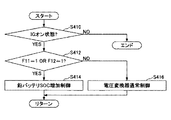
図5は、リチウムイオンバッテリ状態監視部32により実行される処理の一例を示す概略フローチャートである。図6及び図7は、図1に示した2電源システム1の電気系における電流の流れの説明図である。図5に示す処理は、例えば所定周期毎に実行される。
FIG. 5 is a schematic flowchart illustrating an example of processing executed by the lithium ion battery
ステップS500では、リチウムイオンバッテリ状態監視部32は、IGオン状態であるか否かを判定する。判定結果が"YES"の場合は、ステップS502に進み、それ以外の場合(イグニッションスイッチがオフ状態の場合)は終了する。
In step S500, the lithium ion battery
ステップS502では、リチウムイオンバッテリ状態監視部32は、今回の処理周期でイグニッションスイッチのオンイベント(イグニッションスイッチがオフ状態からオンするイベント)があったか否かを判定する。判定結果が"YES"の場合は、ステップS504に進み、それ以外の場合(即ち、今回の処理周期ですでにIGオン状態でった場合)、ステップS512に進む。
In step S502, the lithium ion battery
ステップS504では、リチウムイオンバッテリ状態監視部32は、電圧センサ84の出力値に基づいて、リチウムイオンバッテリ40の開放電圧(図5では、「Li開放電圧」と表記)を取得する。
In step S504, the lithium ion battery
ステップS506では、リチウムイオンバッテリ状態監視部32は、ステップS504で取得した開放電圧に基づいて、リチウムイオンバッテリ40のSOCを算出することで、リチウムイオンバッテリ40のSOC(図5では、「Li_SOC」と表記)を初期化する。例えば、開放電圧からリチウムイオンバッテリ40のSOCは、開放電圧とSOCとの関係を表す特性マップ又は関係式を用いて算出できる。
In step S506, the lithium ion battery
ステップS508では、リチウムイオンバッテリ状態監視部32は、リチウムイオンバッテリ40の積算電流値Itotalを"0"に初期化する。積算電流値Itotalは、放電電流の電流値の積算値(時間軸での積算値、以下同じ)の絶対値と、充電電流の電流値の積算値の絶対値との、和である。
In step S508, the lithium ion battery
ステップS510では、リチウムイオンバッテリ状態監視部32は、スイッチSW2をオンさせる。尚、イグニッションスイッチがオンすると、他のスイッチSW1、SW3もオンする。
In step S510, the lithium ion battery
ステップS512では、リチウムイオンバッテリ状態監視部32は、分極解消中フラグF1が"0"であるか否かを判定する。分極解消中フラグF1が"0"であることは、後述の分極解消処理中でないことを表す。分極解消中フラグF1の初期値(イグニッションスイッチがオンしたときの値)は"0"である。判定結果が"YES"の場合は、ステップS514に進み、それ以外の場合、ステップS538に進む。
In step S512, the lithium ion battery
ステップS514では、リチウムイオンバッテリ状態監視部32は、第2鉛バッテリ充電要求フラグF12が"0"であるか否かを判定する。第2鉛バッテリ充電要求フラグF12が"0"であることは、上述の鉛バッテリSOC増加制御をリチウムイオンバッテリ状態監視部32が要求していない状態を表す。第2鉛バッテリ充電要求フラグF12の初期値(イグニッションスイッチがオンしたときの値)は"0"である。
In step S514, the lithium ion battery
ステップS516では、リチウムイオンバッテリ状態監視部32は、電流センサ83からの情報を取得する。
In step S <b> 516, the lithium ion battery
ステップS518では、リチウムイオンバッテリ状態監視部32は、ステップS516で得た電流センサ83からの情報(放電電流又は充電電流の電流値)に基づいて、積算電流値Itotalを更新する。例えば図5の所定周期をΔTとし、放電電流又は充電電流の電流値の大きさを|I|とすると、積算電流値Itotalは、以下の通り更新されてよい。
(Itotalの今回値)=(Itotalの前回値)+ΔT×|I|
ステップS520では、リチウムイオンバッテリ状態監視部32は、ステップS516で得た電流センサ83からの情報(放電電流又は充電電流の電流値)に基づいて、リチウムイオンバッテリ40のSOCを更新する。例えば、放電電流の電流値の積算値Itotal放電と、充電電流の電流値の積算値Itotal充電とを更新し、積算値Itotal放電と積算値Itotal充電の差分に基づいて、リチウムイオンバッテリ40のSOCを更新する。
In step S518, the lithium ion battery
( Current value of I total ) = (previous value of I total ) + ΔT × | I |
In step S520, the lithium ion battery
ステップS522では、リチウムイオンバッテリ状態監視部32は、ステップS518で得た積算電流値Itotalが所定閾値以上であるか否かを判定する。所定閾値は、ステップS520で得られるリチウムイオンバッテリ40のSOCの精度の低下を検出するための閾値であり、必要な精度等に応じて、試験等により適合される。一般的に、積算電流値Itotalが大きくなるほど、積算の影響に起因して、積算値(積算値Itotal放電や積算値Itotal充電)に基づくSOCの算出精度が悪化していく。従って、必要な精度が厳しいほど所定閾値が小さくなる。判定結果が"YES"の場合は、ステップS524に進み、それ以外の場合、今回周期の処理を終了する。
In step S522, the lithium ion battery
ステップS524では、リチウムイオンバッテリ状態監視部32は、鉛バッテリ4のSOC(図5では、「Pb_SOC」と表記)を取得する。
In step S524, the lithium ion battery
ステップS526では、リチウムイオンバッテリ状態監視部32は、ステップS524で得た鉛バッテリ4のSOCが分極解消可能SOC以上であるか否かを判定する。判定結果が"YES"の場合は、ステップS530に進み、それ以外の場合、ステップS528に進む。
In step S526, the lithium ion battery
ステップS528では、リチウムイオンバッテリ状態監視部32は、第2鉛バッテリ充電要求フラグF12を"1"にセット又は維持する。第2鉛バッテリ充電要求フラグF12が"1"にセットされると、発電機制御部34及び電圧変換器制御部36により鉛バッテリSOC増加制御が実行される(上述の図4AのステップS404及び図4BのステップS414参照)。鉛バッテリSOC増加制御が実行されると、図6にて矢印R1,R2で模式的に電流の流れを示すように、補機5、第2補機50、及び第3補機54への電力供給は、オルタネータ6及びリチウムイオンバッテリ40により実現される。また、図6にて矢印R3で模式的に電流の流れを示すように、オルタネータ6及びリチウムイオンバッテリ40からの電流による鉛バッテリ4の充電が促進される。
In step S528, the lithium ion battery
ステップS530では、リチウムイオンバッテリ状態監視部32は、第2鉛バッテリ充電要求フラグF12を"0"にリセット又は維持する。
In step S530, the lithium ion battery
ステップS532では、リチウムイオンバッテリ状態監視部32は、分極解消中フラグF1を"1"にセットする。
In step S532, the lithium ion battery
ステップS534では、リチウムイオンバッテリ状態監視部32は、分極解消放電時間TaでタイムアウトするタイマTmを起動する。
In step S534, the lithium ion battery
ステップS536では、リチウムイオンバッテリ状態監視部32は、スイッチSW2をオフにする。これにより、リチウムイオンバッテリ40が、鉛バッテリ4、オルタネータ6、補機5、第2補機50、及び第3補機54(即ち2電源システム1の電源回路)から電気的に切り離される。リチウムイオンバッテリ40が2電源システム1の電源回路から電気的に切り離されると、その後の時間の経過とともに、リチウムイオンバッテリ40の分極状態が徐々に解消していく。ステップS536が終了すると、今回周期の処理を終了する。尚、リチウムイオンバッテリ40が2電源システム1の電源回路から電気的に切り離されると、図7にて矢印R11,12で模式的に電流の流れを示すように、補機5、第2補機50、及び第3補機54への電力供給は、オルタネータ6や鉛バッテリ4により実現される。
In step S536, the lithium ion battery
ステップS538では、リチウムイオンバッテリ状態監視部32は、タイマTmがタイムアウトしたか否かを判定する。判定結果が"YES"の場合は、ステップS540に進み、それ以外の場合、ステップS542に進む。
In step S538, the lithium ion battery
ステップS540では、リチウムイオンバッテリ状態監視部32は、電圧センサ84の出力値に基づいて、リチウムイオンバッテリ40の開放電圧を取得する。
In step S540, the lithium ion battery
ステップS542では、リチウムイオンバッテリ状態監視部32は、ステップS540で取得した開放電圧に基づいて、リチウムイオンバッテリ40のSOCを算出することで、リチウムイオンバッテリ40のSOCを初期化する。ステップS506と同様に、開放電圧からのリチウムイオンバッテリ40のSOCの算出は、開放電圧とSOCとの関係を表す特性マップ又は関係式を用いて実現できる。上述のように、リチウムイオンバッテリのSOCと、分極状態でないときのリチウムイオンバッテリの開放電圧とは、高い相関がある。スイッチSWのオフ状態では、リチウムイオンバッテリ40の充放電が実質的にないため、スイッチSWのオフ状態で分極解消放電時間Taが経過すると、リチウムイオンバッテリ40の分極状態が解消している可能性が高い。従って、スイッチSWのオフ状態で分極解消放電時間Taが経過した際に得た開放電圧を用いると、リチウムイオンバッテリ40のSOCを精度良く算出できる。
In step S542, the lithium ion battery
ステップS544では、リチウムイオンバッテリ状態監視部32は、ステップS542でのリチウムイオンバッテリ40のSOCの初期化に伴い、リチウムイオンバッテリ40の積算電流値Itotalを"0"に初期化する。
In step S544, the lithium ion battery
ステップS546では、リチウムイオンバッテリ状態監視部32は、スイッチSW2をオンにする。これにより、リチウムイオンバッテリ40と、鉛バッテリ4、オルタネータ6、補機5、第2補機50、及び第3補機54(即ち2電源システム1の電源回路)との間の電気的な遮断状態が解除される。
In step S546, the lithium ion battery
ステップS548では、リチウムイオンバッテリ状態監視部32は、分極解消中フラグF1を"0"にリセットする。
In step S548, the lithium ion battery
図5に示す処理によれば、積算電流値Itotalが所定閾値以上になった場合に、開放電圧取得処理及びSOC算出処理を実行できるので、算出精度が低下している可能性の高くなったタイミングで、リチウムイオンバッテリ40のSOCを、再び開放電圧に基づいて精度の高い値に更新(補正)できる。
According to the process shown in FIG. 5, since the open circuit voltage acquisition process and the SOC calculation process can be executed when the integrated current value I total is equal to or greater than a predetermined threshold, it is highly possible that the calculation accuracy is reduced. At the timing, the SOC of the
また、図5に示す処理によれば、積算電流値Itotalが所定閾値以上になった際に、鉛バッテリ4のSOCが分極解消可能SOC以上でない場合は、第2鉛バッテリ充電要求フラグF12が"1"にセットされる。第2鉛バッテリ充電要求フラグF12が"1"にセットされると、鉛バッテリ4のSOCが分極解消可能SOC以上になるまで、"1"で維持される(ステップS526、ステップS528参照)。従って、図5に示す処理によれば、積算電流値Itotalが所定閾値以上になった際に、鉛バッテリ4のSOCが分極解消可能SOC以上でない場合は、鉛バッテリ4のSOCが分極解消可能SOC以上になるように、発電機制御部34及び電圧変換器制御部36により鉛バッテリSOC増加制御が実行される。これにより、開放電圧取得処理及びSOC算出処理中に、鉛バッテリ4のSOCが所定の常用下限SOCよりも低下する可能性を低減できる。
Further, according to the process shown in FIG. 5, when the accumulated current value I total is equal to or greater than a predetermined threshold, if the SOC of the lead battery 4 is not equal to or greater than the depolarizable SOC, the second lead battery charge request flag F12 is set. Set to “1”. When the second lead battery charge request flag F12 is set to “1”, the lead battery 4 is maintained at “1” until the SOC of the lead battery 4 becomes equal to or higher than the depolarizable SOC (see steps S526 and S528). Therefore, according to the process shown in FIG. 5, when the accumulated current value I total is equal to or greater than a predetermined threshold, if the SOC of the lead battery 4 is not equal to or greater than the depolarizable SOC, the SOC of the lead battery 4 can be depolarized. The lead battery SOC increase control is executed by the
尚、図5に示す処理では、積算電流値Itotalが所定閾値以上になった際に、鉛バッテリ4のSOCが分極解消可能SOC以上でない場合は、第2鉛バッテリ充電要求フラグF12が"1"にセットされるが、これに限られず、変形例では、第2鉛バッテリ充電要求フラグF12を"1"にセットすることなく、鉛バッテリ4のSOCが分極解消可能SOC以上になるまで待機してもよい。但し、図5に示す処理によれば、積算電流値Itotalが所定閾値以上になった際に直ぐに開放電圧取得処理及びSOC算出処理を実行できない状況下において、当該変形例に比べて速やかに開放電圧取得処理及びSOC算出処理を開始できる。 In the process shown in FIG. 5, when the accumulated current value I total is equal to or greater than a predetermined threshold and the SOC of the lead battery 4 is not equal to or greater than the depolarizable SOC, the second lead battery charge request flag F12 is “1”. However, the present invention is not limited to this, and in a modified example, the second lead battery charge request flag F12 is not set to "1", and the lead battery 4 waits until the SOC of the lead battery 4 becomes equal to or higher than the depolarizable SOC. May be. However, according to the process shown in FIG. 5, in a situation where the open-circuit voltage acquisition process and the SOC calculation process cannot be performed immediately when the integrated current value I total becomes equal to or greater than the predetermined threshold value, the open-circuit is quickly opened compared to the modification. The voltage acquisition process and the SOC calculation process can be started.
尚、図5では、ステップS530に起因して、発電機制御部34及び電圧変換器制御部36による鉛バッテリSOC増加制御は、タイマTmが起動してからタイムアウトするまでの間は、実行されないが、これに限られない。発電機制御部34及び電圧変換器制御部36による鉛バッテリSOC増加制御は、タイマTmが起動してからタイムアウトするまでの間、適宜実行されてもよい。
In FIG. 5, due to step S530, the lead battery SOC increase control by the
次に、図8A乃至図9を参照して、鉛バッテリ4のSOC及びリチウムイオンバッテリ40のSOCの変化態様の例について説明する。
Next, with reference to FIGS. 8A to 9, an example of how the SOC of the lead battery 4 and the SOC of the
図8A及び図8Bは、鉛バッテリ4のSOCの変化態様の一例を示す図である。図8Aは、積算電流値Itotalが所定閾値未満である状況での鉛バッテリ4のSOCの変化態様の説明図である。図8Bは、積算電流値Itotalが所定閾値以上となった後の鉛バッテリ4のSOCの変化態様の説明図である。 FIG. 8A and FIG. 8B are diagrams illustrating an example of a change aspect of the SOC of the lead battery 4. FIG. 8A is an explanatory diagram of an SOC change mode of the lead battery 4 in a situation where the integrated current value I total is less than a predetermined threshold value. FIG. 8B is an explanatory diagram of the SOC change mode of the lead battery 4 after the integrated current value I total becomes equal to or greater than a predetermined threshold value.
図8Aでは、時刻t0にて鉛バッテリ4のSOCが所定の常用下限SOC以下となり、第1鉛バッテリ充電要求フラグF11が"1"となる。これに伴い、鉛バッテリ4のSOCが増加していく。尚、図8Aには、上述の分極解消可能SOCと、常用上限SOCとが併せて示されている。分極解消可能SOCは、常用上限SOC以下で設定され、図6では、常用上限SOCと常用下限SOCとの間の中間値である。このようにして、積算電流値Itotalが所定閾値未満である状況では、鉛バッテリ状態監視部38によって、鉛バッテリ4のSOCが所定の常用下限SOCを有意に下回ることが防止される。
In FIG. 8A, at time t0, the SOC of the lead battery 4 becomes equal to or lower than a predetermined normal lower limit SOC, and the first lead battery charge request flag F11 becomes “1”. As a result, the SOC of the lead battery 4 increases. In FIG. 8A, the above depolarizable SOC and the upper limit SOC are shown together. The depolarizable SOC is set below the normal upper limit SOC, and in FIG. 6, is an intermediate value between the normal upper limit SOC and the normal lower limit SOC. In this way, in a situation where the integrated current value I total is less than the predetermined threshold, the lead battery
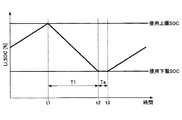
図8Bでは、時刻t1にて積算電流値Itotalが所定閾値以上になり、時刻t1では、鉛バッテリ4のSOCが分極解消可能SOC以上でないため、第2鉛バッテリ充電要求フラグF12が"1"にセットされる。これに伴い、鉛バッテリ4のSOCが増加していく。時刻t1から時間T1経過後の時刻t2では、鉛バッテリ4のSOCが分極解消可能SOC以上となり、第2鉛バッテリ充電要求フラグF12が"0"にセットされる。また、時刻t2には、開放電圧取得処理が開始され、スイッチSW2がオフされる。これに伴い、鉛バッテリ4のSOCが低下していく(図7参照)。時刻t2後、鉛バッテリ4のSOCが常用下限SOCを下回る前に、分極解消放電時間Taが経過し、時刻t2から分極解消放電時間Ta経過後の時刻t3では、スイッチSW2がオンされる。これに伴い、図8Bでは、時刻t3から、鉛バッテリ4のSOCの低下状態が解消される。 In FIG. 8B, the integrated current value I total becomes equal to or greater than the predetermined threshold at time t1, and the SOC of the lead battery 4 is not equal to or higher than the depolarizable SOC at time t1, so the second lead battery charge request flag F12 is “1”. Set to As a result, the SOC of the lead battery 4 increases. At time t2 after time T1 has elapsed from time t1, the SOC of the lead battery 4 becomes equal to or higher than the depolarizable SOC, and the second lead battery charge request flag F12 is set to “0”. At time t2, the open circuit voltage acquisition process is started and the switch SW2 is turned off. Along with this, the SOC of the lead battery 4 decreases (see FIG. 7). After time t2, before the SOC of the lead battery 4 falls below the normal lower limit SOC, the polarization elimination discharge time Ta elapses, and at time t3 after the polarization elimination discharge time Ta elapses from time t2, the switch SW2 is turned on. Accordingly, in FIG. 8B, the SOC reduction state of the lead battery 4 is eliminated from time t3.
図9は、リチウムイオンバッテリ40のSOCの変化態様の一例を示す図である。図9は、図8Bと同じ状況下において、積算電流値Itotalが所定閾値以上となった後のリチウムイオンバッテリ40のSOCの変化態様の説明図である。
FIG. 9 is a diagram illustrating an example of a change mode of the SOC of the
図9では、図8Bと同様、時刻t1にて積算電流値Itotalが所定閾値以上になり、時刻t1では、鉛バッテリ4のSOCが分極解消可能SOC以上でないため、第2鉛バッテリ充電要求フラグF12が"1"にセットされる。これに伴い、リチウムイオンバッテリ40からの電流により鉛バッテリ4が充電され、リチウムイオンバッテリ40のSOCが低下していく。時刻t1から時間T1経過後の時刻t2では、鉛バッテリ4のSOCが分極解消可能SOC以上となり、第2鉛バッテリ充電要求フラグF12が"0"にセットされる。また、時刻t2には、開放電圧取得処理が開始され、スイッチSW2がオフされる。これに伴い、リチウムイオンバッテリ40のSOCは維持される。尚、図9では、リチウムイオンバッテリ40のSOCは使用下限SOCまで低下した状態で維持されている。時刻t2から分極解消放電時間Ta経過後の時刻t3では、開放電圧取得処理及びSOC算出処理の完了に伴い、スイッチSW2がオンされる。これに伴い、図9では、時刻t3から、リチウムイオンバッテリ40が充電され、リチウムイオンバッテリ40のSOCが増加していく。
In FIG. 9, as in FIG. 8B, the accumulated current value I total becomes equal to or greater than the predetermined threshold at time t < b> 1, and the SOC of the lead battery 4 is not equal to or greater than the depolarizable SOC at time t <b> 1. F12 is set to "1". Along with this, the lead battery 4 is charged by the current from the
以上、各実施例について詳述したが、特定の実施例に限定されるものではなく、特許請求の範囲に記載された範囲内において、種々の変形及び変更が可能である。また、前述した実施例の構成要素を全部又は複数を組み合わせることも可能である。 Although each embodiment has been described in detail above, it is not limited to a specific embodiment, and various modifications and changes can be made within the scope described in the claims. It is also possible to combine all or a plurality of the components of the above-described embodiments.
1 電源システム
2 エンジン
4 鉛バッテリ
5 補機
6 オルタネータ
30 電源制御装置
32 リチウムイオンバッテリ状態監視部
34 発電機制御部
36 電圧変換器制御部
38 鉛バッテリ状態監視部
40 リチウムイオンバッテリ
50 第2補機
54 第3補機
60 電圧変換器
80 電流センサ
82 電圧センサ
83 電流センサ
84 電圧センサ
DESCRIPTION OF
Claims (7)
前記電源回路に設けられる第2バッテリであり、前記第1バッテリに並列に電気的に接続され、リチウムイオンバッテリである第2バッテリと、
前記電源回路に設けられ、前記第1バッテリ及び前記第2バッテリに並列に電気的に接続された電気負荷と、
前記電源回路に設けられ、開状態のときは前記第2バッテリを前記電源回路から電気的に切り離すスイッチと、
イグニッションスイッチがオン状態でありかつ前記第1バッテリのSOCが所定のSOC以上である状態において、前記スイッチを開き、前記スイッチを開いてから所定時間経過した後に、前記第2バッテリの開放電圧を取得する開放電圧取得処理を行うように構成された制御装置とを含む、電源システム。 A first battery provided in a power circuit;
A second battery provided in the power supply circuit, electrically connected in parallel to the first battery, and a second battery that is a lithium ion battery;
An electrical load provided in the power supply circuit and electrically connected in parallel to the first battery and the second battery;
A switch provided in the power supply circuit to electrically disconnect the second battery from the power supply circuit when in an open state;
When the ignition switch is on and the SOC of the first battery is greater than or equal to a predetermined SOC, the switch is opened, and after a predetermined time has elapsed since the switch was opened, the open voltage of the second battery is acquired. And a control device configured to perform an open circuit voltage acquisition process.
前記充電処理は、前記第2バッテリ及び前記オルタネータを用いて前記第1バッテリを充電することを含む、請求項4に記載の電源システム。 An alternator provided in the power supply circuit and electrically connected in parallel to the first battery, the second battery and the electric load;
The power supply system according to claim 4, wherein the charging process includes charging the first battery using the second battery and the alternator.
Priority Applications (3)
| Application Number | Priority Date | Filing Date | Title |
|---|---|---|---|
| JP2017030442A JP6562015B2 (en) | 2017-02-21 | 2017-02-21 | Power system |
| US15/894,411 US10587129B2 (en) | 2017-02-21 | 2018-02-12 | Electric power supply system |
| CN201810150242.7A CN108462246B (en) | 2017-02-21 | 2018-02-13 | Power supply system |
Applications Claiming Priority (1)
| Application Number | Priority Date | Filing Date | Title |
|---|---|---|---|
| JP2017030442A JP6562015B2 (en) | 2017-02-21 | 2017-02-21 | Power system |
Publications (2)
| Publication Number | Publication Date |
|---|---|
| JP2018137885A JP2018137885A (en) | 2018-08-30 |
| JP6562015B2 true JP6562015B2 (en) | 2019-08-21 |
Family
ID=63167453
Family Applications (1)
| Application Number | Title | Priority Date | Filing Date |
|---|---|---|---|
| JP2017030442A Active JP6562015B2 (en) | 2017-02-21 | 2017-02-21 | Power system |
Country Status (3)
| Country | Link |
|---|---|
| US (1) | US10587129B2 (en) |
| JP (1) | JP6562015B2 (en) |
| CN (1) | CN108462246B (en) |
Families Citing this family (8)
| Publication number | Priority date | Publication date | Assignee | Title |
|---|---|---|---|---|
| JP6551089B2 (en) * | 2015-09-11 | 2019-07-31 | 株式会社オートネットワーク技術研究所 | Automotive power supply |
| JP6540565B2 (en) * | 2016-03-16 | 2019-07-10 | 株式会社オートネットワーク技術研究所 | Power supply system for vehicle, drive system for vehicle |
| US11289929B2 (en) * | 2018-02-23 | 2022-03-29 | Volvo Construction Equipment Ab | Method for evaluating a state of charge of a rechargeable battery |
| JP6962265B2 (en) * | 2018-04-24 | 2021-11-05 | トヨタ自動車株式会社 | Control devices, control methods and battery systems, and electric vehicles equipped with them |
| JP7120173B2 (en) * | 2019-07-11 | 2022-08-17 | トヨタ自動車株式会社 | Control device |
| JP2022117838A (en) * | 2021-02-01 | 2022-08-12 | ヤマハ発動機株式会社 | Power supply system for ship |
| CN114019389A (en) * | 2021-10-22 | 2022-02-08 | 杭州华塑科技股份有限公司 | Battery open circuit detection method and device, electronic equipment and storage medium |
| CN115208024A (en) * | 2022-07-29 | 2022-10-18 | 三一汽车制造有限公司 | Power supply control method, device and system and working machine |
Family Cites Families (12)
| Publication number | Priority date | Publication date | Assignee | Title |
|---|---|---|---|---|
| JP3345519B2 (en) * | 1994-06-08 | 2002-11-18 | 富士通株式会社 | Power supply |
| WO2005116675A1 (en) | 2004-05-26 | 2005-12-08 | Nec Lamilion Energy, Ltd. | Secondary battery residual-capacity estimating method and apparatus |
| JP2009073266A (en) * | 2007-09-19 | 2009-04-09 | Auto Network Gijutsu Kenkyusho:Kk | Power supply device |
| EP2272722B1 (en) * | 2009-07-01 | 2015-04-08 | Denso Corporation | Power source apparatus for vehicle |
| JP5704108B2 (en) | 2012-03-30 | 2015-04-22 | トヨタ自動車株式会社 | Battery system and estimation method |
| JP6011135B2 (en) * | 2012-08-09 | 2016-10-19 | 株式会社デンソー | Power system |
| JP6098496B2 (en) * | 2013-12-06 | 2017-03-22 | トヨタ自動車株式会社 | Power storage system |
| JP6115484B2 (en) | 2014-01-22 | 2017-04-19 | 株式会社デンソー | Battery charge rate estimation device |
| JP6303812B2 (en) * | 2014-05-26 | 2018-04-04 | トヨタ自動車株式会社 | Power supply control device and power supply control method |
| US10481210B2 (en) * | 2014-07-14 | 2019-11-19 | Ford Global Technologies, Llc | Methods to determine battery cell voltage relaxation time based on cell usage history and temperature |
| JP6369340B2 (en) * | 2015-01-28 | 2018-08-08 | 株式会社豊田自動織機 | Power storage device and method for controlling power storage device |
| CN105403839B (en) * | 2015-10-27 | 2019-04-05 | 北京新能源汽车股份有限公司 | Method and device for estimating state of charge of battery |
-
2017
- 2017-02-21 JP JP2017030442A patent/JP6562015B2/en active Active
-
2018
- 2018-02-12 US US15/894,411 patent/US10587129B2/en active Active
- 2018-02-13 CN CN201810150242.7A patent/CN108462246B/en not_active Expired - Fee Related
Also Published As
| Publication number | Publication date |
|---|---|
| US10587129B2 (en) | 2020-03-10 |
| CN108462246A (en) | 2018-08-28 |
| JP2018137885A (en) | 2018-08-30 |
| US20180241225A1 (en) | 2018-08-23 |
| CN108462246B (en) | 2021-06-22 |
Similar Documents
| Publication | Publication Date | Title |
|---|---|---|
| JP6562015B2 (en) | Power system | |
| JP4459997B2 (en) | On-vehicle battery state estimation device, internal combustion engine automatic stop / start device, and internal combustion engine automatic stop / start system | |
| JP5050325B2 (en) | Battery control device | |
| US8552688B2 (en) | On-vehicle battery condition estimation device | |
| JP5288170B2 (en) | Battery temperature rise control device | |
| JP6598542B2 (en) | Power supply device and control method of power supply device | |
| WO2001018938A1 (en) | Apparatus for battery capacity measurement and for remaining capacity calculation | |
| JP5493407B2 (en) | Battery pack capacity adjustment device | |
| JP2008064496A (en) | Battery control apparatus, electric vehicle, and program for making computer execute processing for estimation for charged condition of secondary battery | |
| JP2007159280A (en) | Power supply unit for vehicle | |
| JP6548699B2 (en) | Power supply system | |
| JP2000324702A (en) | Method and apparatus for detecting discharge capacity of battery and controller for car battery | |
| JP4936017B2 (en) | Battery temperature rise control device | |
| JP5026362B2 (en) | Automatic stop and start device for internal combustion engine | |
| US10498154B2 (en) | Electric power system | |
| CN107921916B (en) | Vehicle-mounted power supply device | |
| JP6969505B2 (en) | In-vehicle power control device and in-vehicle power supply system | |
| JP2007244007A (en) | Charge controller and controlling method of battery for vehicle | |
| JP6530334B2 (en) | Vehicle charge control device | |
| JP6686556B2 (en) | Power system | |
| JP5954188B2 (en) | Secondary battery management device | |
| JP5996386B2 (en) | Charge / discharge control circuit, power supply device for vehicle, and failure determination method | |
| JP6513516B2 (en) | Power supply and control method of power supply | |
| JP5277819B2 (en) | Power storage device | |
| JP5964214B2 (en) | Charge / discharge control circuit, power supply device for vehicle, and failure determination method |
Legal Events
| Date | Code | Title | Description |
|---|---|---|---|
| A621 | Written request for application examination |
Free format text: JAPANESE INTERMEDIATE CODE: A621 Effective date: 20180913 |
|
| A977 | Report on retrieval |
Free format text: JAPANESE INTERMEDIATE CODE: A971007 Effective date: 20190613 |
|
| TRDD | Decision of grant or rejection written | ||
| A01 | Written decision to grant a patent or to grant a registration (utility model) |
Free format text: JAPANESE INTERMEDIATE CODE: A01 Effective date: 20190625 |
|
| A61 | First payment of annual fees (during grant procedure) |
Free format text: JAPANESE INTERMEDIATE CODE: A61 Effective date: 20190708 |
|
| R151 | Written notification of patent or utility model registration |
Ref document number: 6562015 Country of ref document: JP Free format text: JAPANESE INTERMEDIATE CODE: R151 |