JP6561609B2 - Heater and image forming apparatus - Google Patents
Heater and image forming apparatus Download PDFInfo
- Publication number
- JP6561609B2 JP6561609B2 JP2015121022A JP2015121022A JP6561609B2 JP 6561609 B2 JP6561609 B2 JP 6561609B2 JP 2015121022 A JP2015121022 A JP 2015121022A JP 2015121022 A JP2015121022 A JP 2015121022A JP 6561609 B2 JP6561609 B2 JP 6561609B2
- Authority
- JP
- Japan
- Prior art keywords
- resistance heating
- heater
- heating element
- sheet passing
- passing portion
- Prior art date
- Legal status (The legal status is an assumption and is not a legal conclusion. Google has not performed a legal analysis and makes no representation as to the accuracy of the status listed.)
- Active
Links
Images


Description
本発明の実施形態は、ヒータおよび画像形成装置に関する。 Embodiments described herein relate generally to a heater and an image forming apparatus.
OA機器、家電用電気製品、精密製造設備などの電子機器類にヒータが装着されている。ヒータは、例えば、複写機やファクシミリなどの画像形成装置において用紙にトナーを定着する画像形成装置に用いられる。また、リライタブルカードリーダであれば印字消去などに用いられる。ヒータは、給電用電極、導体、抵抗発熱体が基板上に形成されていることで構成され、給電用電極から供給された電力により、抵抗発熱体が発熱する。 Heaters are mounted on electronic devices such as office automation equipment, home appliances, and precision manufacturing equipment. The heater is used in an image forming apparatus that fixes toner onto a sheet in an image forming apparatus such as a copying machine or a facsimile. In addition, a rewritable card reader is used for erasing printing. The heater is configured by forming a power supply electrode, a conductor, and a resistance heating element on a substrate, and the resistance heating element generates heat by the power supplied from the power supply electrode.
抵抗発熱体の材料として一般的に、抵抗温度係数[ppm/℃]が0あるいは正となる、PTC(Positive Temperature Coefficient)特性を持つ材料で形成する方法がある。 As a material for the resistance heating element, there is generally a method of forming a material having a PTC (Positive Temperature Coefficient) characteristic in which the resistance temperature coefficient [ppm / ° C.] is 0 or positive.
PTC特性の抵抗発熱体は、総じてシート抵抗値が低く、一つのヒータに形成する抵抗発熱体の総抵抗値を商用電源で使用できる範囲に設定することは困難である。そこで、ヒータの長手方向において、抵抗発熱体を複数に分割し、かつ各抵抗発熱体でヒータの短手方向に電流が流れるように、一対の導体をヒータの短手方向の両端に配設することで、総抵抗値を上げながら所望とする発熱量を実現している。 The resistance heating elements having PTC characteristics generally have a low sheet resistance value, and it is difficult to set the total resistance value of the resistance heating elements formed in one heater within a range that can be used with a commercial power source. Therefore, in the longitudinal direction of the heater, the resistance heating element is divided into a plurality of pieces, and a pair of conductors are arranged at both ends in the short direction of the heater so that current flows in the short direction of the heater in each resistance heating element. Thus, a desired amount of heat generation is realized while increasing the total resistance value.
ヒータは、加熱できる最大サイズよりも小さいサイズの紙等が連続して通過する場合、非通紙部の領域が過度に昇温する。そこで非通紙部に配設される抵抗発熱体の抵抗値や配設される間隔等を調整し、昇温対策を実施している。しかしながら従来の調整方法では、所望とする発熱分布を得ることが困難であった。 When the paper having a size smaller than the maximum size that can be heated continuously passes through the heater, the temperature of the non-sheet passing portion is excessively increased. In view of this, the resistance value of the resistance heating element disposed in the non-sheet passing portion, the interval between the resistance heating elements, and the like are adjusted to take measures against temperature rise. However, with the conventional adjustment method, it has been difficult to obtain a desired heat generation distribution.
本発明は、所望の発熱分布を実現することができる、PTC特性のヒータ及び画像形成装置を提供する。 The present invention provides a PTC characteristic heater and an image forming apparatus capable of realizing a desired heat generation distribution.
実施形態のヒータは、長尺な基板と;前記基板上の長手方向に沿って設けられる一対の導体と;前記一対の導体の間に電気的に並列接続されて設けられる複数の抵抗発熱体と;を具備し、前記抵抗発熱体は、PTC特性を有しており、前記基板の短手方向において、並設される前記抵抗発熱体の少なくとも一部がオーバーラップするように斜設されており、前記導体と接続される角度が前記基板の長手方向において任意となるように設けられることを特徴とする。 The heater according to the embodiment includes a long substrate; a pair of conductors provided along a longitudinal direction on the substrate; and a plurality of resistance heating elements provided in electrical parallel connection between the pair of conductors. And the resistance heating element has a PTC characteristic, and is arranged obliquely so that at least a part of the resistance heating elements arranged in parallel overlap each other in the lateral direction of the substrate. The angle to be connected to the conductor is set to be arbitrary in the longitudinal direction of the substrate.
本発明によれば、所望とする発熱分布を実現することができる、PTC特性のヒータ及び画像形成装置を提供することができる。 According to the present invention, it is possible to provide a PTC characteristic heater and an image forming apparatus capable of realizing a desired heat generation distribution.
以下、図面を参照して各実施形態を説明する。 Hereinafter, each embodiment will be described with reference to the drawings.
なお、図面は模式的または概念的なものであり、各部分の寸法や比率などは、必ずしも現実のものと同一とは限らない。また、各図面において同じ構成および作用効果については、同一符号を用いてその説明を省略する。 The drawings are schematic or conceptual, and the dimensions and ratios of each part are not necessarily the same as actual ones. Moreover, about the same structure and effect in each drawing, the description is abbreviate | omitted using the same code | symbol.
以下、従来のヒータの構成を、図1、図2を参照して説明する。 Hereinafter, the configuration of a conventional heater will be described with reference to FIGS. 1 and 2.
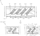
図1に例示するように、ヒータ1Aは、基板2と、一対の導体3と、抵抗発熱体4anと、を具備する。ここでnとは正の整数であり、抵抗発熱体4anが基板2上で配設される数量を表す。従来のヒータ1Aの基板2長手方向に、例えば31個の抵抗発熱体4a1〜4a31を形成する。
As illustrated in FIG. 1, the heater 1A includes a
図2に例示するようにヒータ1Aは、導体3a、3bの間に並設される複数の抵抗発熱体4anの斜設される角度θが、ヒータ1A長手方向において一様に形成されている。抵抗発熱体4anの斜設される角度θとは、並設される抵抗発熱体4anどうしがヒータ1A短手方向においてオーバーラップする対角どうしを結ぶ直線L1と、一方の対角が導体3に接続される端部どうしをヒータ1A長手方向において結ぶ直線L2との間の角度として定義する。
As illustrated in FIG. 2, in the
また各抵抗発熱体4anの長さAnと幅Bn、抵抗発熱体4anが導体3a、3bと接続される角度θ4anも、基板2長手方向において一様に形成されている。角度θ4anは、抵抗発熱体4anと導体3とが接続される面に引かれる直線L3と、並設される抵抗発熱体4anどうしが基板2短手方向においてオーバーラップする対角の一方が、導体3に接続される端部どうしを基板2長手方向において結ぶ直線L2との間の角度として定義する。
Further, the length An and the width Bn of each resistance heating element 4an and the angle θ4an at which the resistance heating element 4an is connected to the
図1に例示するように、各抵抗発熱体4anが基板2長手方向において発熱する領域を、発熱領域Tnとし、ヒータ1Aが基板2長手方向において発熱する領域を発熱領域Tとすると、T=Tn×31となる。例えば、基板2中央の抵抗発熱体4a11〜4a21が形成される発熱領域T11〜T21を通紙部とし、基板2両端の抵抗発熱体4a1〜4a10が形成されるT1〜T10と、抵抗発熱体4a22〜4a31が形成される発熱領域T22〜T31を非通紙部とする。
As illustrated in FIG. 1, assuming that a region where each resistance heating element 4an generates heat in the longitudinal direction of the
例えば、小さいサイズの紙等が連続してヒータ1Aを通過する場合、基板2端部は非通紙部となるため、徐々に昇温する現象が発生する。非通紙部が過度に昇温すると、ヒータ1Aが搭載されるプリンターの部品が損傷する可能性がある。また、非通紙部が昇温した状態で大きいサイズの記録媒体が通過すると、高温オフセットとなり、トナーが均一に定着しないなどの不具合が起こりやすくなる。
For example, when small-size paper or the like passes through the heater 1A continuously, the end of the
非通紙部の昇温対策として、例えば基板2端部における抵抗発熱体4anの材料を調整する方法がある。基板2端部に配設される抵抗発熱体4anを、高抵抗値の抵抗体ペーストを用いて構成する場合、電流が流れにくくなるため発熱量を抑制することが可能となる。しかし抵抗発熱体4anの形成時に少なくとも2種類の抵抗体ペーストを使用するため、工程数が増え製造コスト増加につながる。また、基板2上に抵抗体ペーストを塗布する際、抵抗値の異なる抵抗体ペースト同士が混同しないよう、工程上の位置ずれを考慮して、抵抗発熱体4an同士の間隔を広くとる必要がある。その場合、基板2長手方向において抵抗発熱体4anが形成されない領域が広くなり、ヒータ1Aの発熱分布が不均一になりやすい。また、抵抗発熱体4anの配設数が減少することにより、温度分布を細かく調整することが困難となる。
As a countermeasure for raising the temperature of the non-sheet passing portion, for example, there is a method of adjusting the material of the resistance heating element 4an at the end portion of the
従来の非通紙部昇温対策として、基板両端部における抵抗発熱体4anの幅Bnを狭く形成し、発熱量を減少させる方法を、図3を参照して説明する。 As a conventional countermeasure for raising the temperature of the non-sheet passing portion, a method of reducing the heat generation amount by forming the width Bn of the resistance heating element 4an at both ends of the substrate narrow will be described with reference to FIG.
例えば、ヒータ1B長手方向の非通紙部における抵抗発熱体4a1〜4a10と4a22〜4a31の幅Bnを、基板2通紙部における抵抗発熱体4a11〜4a21の幅Bnよりも狭く形成する。図3に例示するように、抵抗発熱体4a22の幅B22は、隣り合う抵抗発熱体4a21の幅B21よりも狭く形成されている。これにより、抵抗発熱体4a22は高抵抗化するため電流が流れにくくなり、発熱量が減少する。したがって非通紙部における抵抗発熱体4anの幅Bnを狭く形成する場合、非通紙部における発熱量は減少する。
For example, the widths Bn of the resistance heating elements 4a1 to 4a10 and 4a22 to 4a31 in the non-sheet passing portion in the longitudinal direction of the heater 1B are formed narrower than the width Bn of the resistance heating elements 4a11 to 4a21 in the
しかしこの場合、ヒータ1B通紙方向視において抵抗発熱体4anが存在しない非発熱領域Gが形成される。例えば図3に例示するように、抵抗発熱体4a21、4a22、4a23それぞれの発熱領域T21、T22、T23の間には非発熱領域Gが形成されている。非発熱領域Gは、ヒータ1Bの通紙方向視において抵抗発熱体4anが形成されない領域であるため発熱せず、非発熱領域Gの面積が広いほどヒータ1Bの発熱分布が不均一となり、通過する記録媒体に、部分的なトナー定着不良が発生する。この対策として、例えば非通紙部の抵抗発熱体4anを近接して並設し、非発熱領域Gが形成されないようにする方法がある。しかしこの場合、基板2長手方向の発熱領域Tの長さが短くなるため、抵抗発熱体4anを配設する数量を増やす必要が生じてくる。
However, in this case, a non-heat generating region G where the resistance heating element 4an does not exist in the heater 1B sheet passing direction is formed. For example, as illustrated in FIG. 3, a non-heat generating region G is formed between the heat generating regions T21, T22, T23 of the resistance heating elements 4a21, 4a22, 4a23. The non-heat generating region G is a region where the resistance heating element 4an is not formed when the heater 1B is viewed in the sheet passing direction, and therefore does not generate heat. The larger the area of the non-heat generating region G, the more uneven the heat generation distribution of the heater 1B. Partial toner fixing failure occurs on the recording medium. As a countermeasure, for example, there is a method in which the resistance heating elements 4an in the non-sheet passing portion are arranged in close proximity so that the non-heating area G is not formed. However, in this case, since the length of the heat generating region T in the longitudinal direction of the
他の非通紙部昇温対策として、基板非通紙部における抵抗発熱体4anの長さAnを長く形成し、発熱量を減少させる方法を、図4を参照して説明する。 As another non-sheet-passing portion temperature rise countermeasure, a method of increasing the length An of the resistance heating element 4an in the substrate non-sheet-passing portion and reducing the heat generation will be described with reference to FIG.
例えば、ヒータ1C長手方向の非通紙部における抵抗発熱体4a1〜4a10、4a22〜4a31の長さAnを、ヒータ1C通紙部における抵抗発熱体4a11〜4a21の長さAnよりも長く形成する。図4に例示するように、抵抗発熱体4a22の長さA22は、隣り合う抵抗発熱体4a21の長さA21よりも長く形成されている。これにより、抵抗発熱体4a22は高抵抗化するため電流が流れにくくなり、発熱量が減少する。したがって非通紙部における抵抗発熱体4anの長さAnを長く形成する場合、非通紙部における発熱量は減少する。 For example, the length An of the resistance heating elements 4a1 to 4a10 and 4a22 to 4a31 in the non-sheet passing portion in the longitudinal direction of the heater 1C is formed longer than the length An of the resistance heating elements 4a11 to 4a21 in the heater 1C sheet passing portion. As illustrated in FIG. 4, the length A22 of the resistance heating element 4a22 is formed to be longer than the length A21 of the adjacent resistance heating element 4a21. Thereby, since the resistance heating element 4a22 has a high resistance, it becomes difficult for current to flow, and the amount of heat generation is reduced. Therefore, when the length An of the resistance heating element 4an in the non-sheet passing portion is long, the amount of heat generated in the non-sheet passing portion is reduced.
しかしこの場合、ヒータ1Cの通紙方向視において、抵抗発熱体4a22の発熱領域T22と、隣り合う抵抗発熱体4a23の発熱領域T23の一部が重なっている。非通紙部における発熱領域T22とT23が重なる面積は、通紙部における発熱領域T20とT21が重なる面積よりも広く形成されている。このため、ヒータ1Cでは、通過する箇所によって記録媒体が受け取る熱量に差が生じ、トナー定着が不均一となるおそれがある。 However, in this case, when viewed in the paper passing direction of the heater 1C, the heat generation region T22 of the resistance heating element 4a22 and a part of the heat generation region T23 of the adjacent resistance heating element 4a23 overlap each other. The area where the heat generation regions T22 and T23 overlap in the non-sheet passing portion is formed wider than the area where the heat generation regions T20 and T21 overlap in the sheet passing portion. For this reason, in the heater 1C, there is a possibility that the amount of heat received by the recording medium varies depending on the passage location, and toner fixing may be uneven.
この対策として、ヒータ1Cの非通紙部において抵抗発熱体4anの間隔を広げて並設し、発熱領域Tnが重ならないように形成する方法がある。ただし、ヒータ1C長手方向の発熱領域Tの長さに制約がある場合、抵抗発熱体4anが配設される数量を少なくする必要が生じてくる。 As a countermeasure, there is a method in which the resistance heating elements 4an are arranged in parallel at the non-sheet passing portion of the heater 1C so as not to overlap the heating regions Tn. However, when the length of the heat generating region T in the longitudinal direction of the heater 1C is limited, it is necessary to reduce the number of the resistance heating elements 4an disposed.
非通紙部の昇温対策として、抵抗発熱体4anの長さAnや幅Bnを調整する場合、上述するようにヒータ1B、1Cの長手方向における発熱領域Tの長さが変動したり、抵抗発熱体4anが配設される数量を調整したりする必要が生じる。 When adjusting the length An or the width Bn of the resistance heating element 4an as a countermeasure for raising the temperature of the non-sheet passing portion, as described above, the length of the heat generation region T in the longitudinal direction of the heaters 1B and 1C varies, It is necessary to adjust the number of the heating elements 4an disposed.
本発明に係るヒータ1は、抵抗発熱体4anと導体3a、3bとが接続される角度を基板2長手方向において調整することによって、抵抗発熱体4anの抵抗値を変化させることができる。その際、基板2長手方向における発熱領域Tの長さや抵抗発熱体4anが配設される数量を考慮することなく、所望とする発熱分布を実現することを可能とする。
The
第1の実施形態について、図5を参照して説明する。 The first embodiment will be described with reference to FIG.
一対をなす導体3a、3bは、ヒータ1Dの一方の面上に設けられ、抵抗発熱体4anに電力を供給するものである。導体3a、3bは、ヒータ1Dの短手方向における幅を一定とし、ヒータ1Dの長手方向に沿って互いに所定の間隔を保って形成される。導体3a、3bは、抵抗発熱体4anと比較して抵抗値が十分低い銀(Ag)等の導体ペーストで構成されている。
The pair of
抵抗発熱体4anはPTC特性を有し、ヒータ1Dの長手方向に互いに離間するように複数に分割して並設されている。複数の抵抗発熱体4anは、導体3a、3bの間に並列接続され、導体3aと3bを電気的に直列接続している。複数の抵抗発熱体4anは、ヒータ1Dの短手方向において、並設される抵抗発熱体4anの少なくとも一部がオーバーラップするように斜設されている。
The resistance heating element 4an has PTC characteristics, and is divided and arranged in parallel so as to be separated from each other in the longitudinal direction of the heater 1D. The plurality of resistance heating elements 4an are connected in parallel between the
本実施形態におけるヒータ1Dは、通紙部における抵抗発熱体4anと導体3a、3bとの接続角度を調整している。これにより、通紙部における抵抗発熱体4anの抵抗値は、非通紙部における抵抗発熱体4anの抵抗値よりも小さくなる。ここで、抵抗発熱体4anと導体3a、3bとの調整前の接続角度と、調整後の接続角度との差をΔθ1と定義する。
The heater 1D in the present embodiment adjusts the connection angle between the resistance heating element 4an and the
ヒータ1Dの通紙部上に並設される複数の抵抗発熱体4anは、斜設される角度θが、ヒータ1D長手方向において一様に形成されている。また、抵抗発熱体4anと導体3a、3bとが接続される角度θ4anは、ヒータ1D中央の通紙部と両端の非通紙部では異なる角度に形成されている。
In the plurality of resistance heating elements 4an arranged side by side on the sheet passing portion of the heater 1D, the oblique angle θ is uniformly formed in the longitudinal direction of the heater 1D. Further, the angle θ4an at which the resistance heating element 4an and the
図5に例示するように、ヒータ1D通紙部に形成される抵抗発熱体4a21が、導体3a、3bと接続される角度をθ4a21とする。また、ヒータ1D非通紙部に形成される抵抗発熱体4a22が、導体3a、3bと接続される角度をθ4a22とする。θ4a21は、調整前の大きさがθ4a22と同等であり、調整後はθ4a22よりもΔθ1小さく形成されており、以下の式となる。
As illustrated in FIG. 5, an angle at which the resistance heating element 4a21 formed in the heater 1D paper passing portion is connected to the
θ4a21=θ4a22−Δθ1 θ4a21 = θ4a22−Δθ1
θ4a21がθ4s22よりもΔθ1小さく形成されることにより、抵抗発熱体4a21の幅B21は変化しないが、長さA21は抵抗発熱体4a22の長さA22と比較して、短く形成されている。そのため、抵抗発熱体4a21は、抵抗発熱体4a22と比較して低抵抗となり、電流が流れやすくなるため発熱量が大きくなる。 By forming θ4a21 smaller than θ4s22 by Δθ1, the width B21 of the resistance heating element 4a21 does not change, but the length A21 is shorter than the length A22 of the resistance heating element 4a22. Therefore, the resistance heating element 4a21 has a lower resistance than the resistance heating element 4a22, and the current easily flows, so that the amount of heat generation increases.
このように、通紙部における抵抗発熱体4anが導体3a、3bと接続される角度が、非通紙部における抵抗発熱体4anが導体3a、3bと接続される角度よりΔθ1小さく形成されることにより、通紙部は非通紙部と比較して発熱量を大きくすることが可能となる。したがってヒータ1Dを記録媒体が通過する際、非通紙部の過度の昇温を抑制することが可能となる。
In this way, the angle at which the resistance heating element 4an in the sheet passing portion is connected to the
本実施形態において、通紙部における抵抗発熱体4anの斜設される角度θと、並設される抵抗発熱体4anどうしがヒータ1D短手方向においてオーバーラップする対角どうしを結ぶ直線の長さL1は、ヒータ1D長手方向において一様となるよう形成されている。これにより、抵抗発熱体4anと導体3a、3bとの接続角度θ4anを調整しても、複数の抵抗発熱体4anの各発熱領域Tnは、ヒータ1D長手方向においてすべて同等の長さに形成することが可能となる。これにより、ヒータ1D長手方向の発熱領域Tは、ヒータ1A長手方向の発熱領域Tと同等の長さに形成される。
In the present embodiment, the length of a straight line connecting the oblique angle θ of the resistance heating elements 4an in the sheet passing portion and the diagonals where the resistance heating elements 4an arranged side by side overlap in the heater 1D short direction. L1 is formed to be uniform in the longitudinal direction of the heater 1D. Thereby, even if the connection angle θ4an between the resistance heating element 4an and the
従来の昇温対策のように、並設される発熱領域Tnがヒータ1Dの通紙方向視で重なったり、非発熱領域Gが形成されたりするなどの現象が生じないため、抵抗発熱体4anの配設数や発熱領域Tの長さを調整する必要がない。抵抗発熱体4anと導体3a、3bとの接続角度を調整することにより、抵抗発熱体4anを所望の抵抗値に調整することができ、ヒータ1Tの非通紙部における過度の昇温を抑制することが可能となる。
Unlike conventional temperature rise countermeasures, the phenomenon that the heat generation regions Tn arranged side by side overlap with each other when the heater 1D is viewed in the sheet passing direction or the non-heat generation region G is not formed occurs. There is no need to adjust the number of arrangements or the length of the heat generating region T. By adjusting the connection angle between the resistance heating element 4an and the
次に、第2の実施形態について、図6を参照して説明する。 Next, a second embodiment will be described with reference to FIG.
本実施形態におけるヒータ1Eは、通紙部における抵抗発熱体4anと導体3a、3bとの接続角度を調整している。これにより、通紙部における抵抗発熱体4anの抵抗値は、非通紙部における抵抗発熱体4anの抵抗値よりも小さくなる。ここで、抵抗発熱体4anと導体3a、3bとの元の接続角度と、調整後の接続角度との差をΔθ2と定義する。
The heater 1E according to the present embodiment adjusts the connection angle between the resistance heating element 4an and the
ヒータ1Eの通紙部上に並設される複数の抵抗発熱体4anは、斜設される角度θが、ヒータ1E長手方向において一様に形成されている。また、抵抗発熱体4anと導体3a、3bとが接続される角度θ4anは、ヒータ1E中央の通紙部と両端の非通紙部では異なる角度に形成されている。
In the plurality of resistance heating elements 4an arranged side by side on the sheet passing portion of the heater 1E, the oblique angle θ is uniformly formed in the longitudinal direction of the heater 1E. Further, the angle θ4an at which the resistance heating element 4an and the
図6に例示するように、ヒータ1E通紙部に形成される抵抗発熱体4a21が、導体3a、3bと接続される角度をθ4a21とする。また、ヒータ1E非通紙部に形成される抵抗発熱体4a22が、導体3a、3bと接続される角度をθ4a22とする。θ4a21は、調整前の大きさがθ4a22と同等であり、調整後はθ4a22よりもΔθ2小さく形成されており、以下の式となる。
As illustrated in FIG. 6, an angle at which the resistance heating element 4a21 formed in the heater 1E paper passing portion is connected to the
θ4a21=θ4a22−Δθ2 θ4a21 = θ4a22−Δθ2
θ4a21がθ4a22よりもΔθ2小さく形成されることにより、抵抗発熱体4a21の長さA21は抵抗発熱体4a22の長さA22と比較して、短く形成されている。また、抵抗発熱体4a21の幅B21は、抵抗発熱体4a22の幅B22よりも広く形成されている。そのため、抵抗発熱体4a21は、抵抗発熱体4a22と比較して低抵抗となり、電流が流れやすくなるため発熱量が大きくなる。 By forming θ4a21 smaller by Δθ2 than θ4a22, the length A21 of the resistance heating element 4a21 is formed shorter than the length A22 of the resistance heating element 4a22. Further, the width B21 of the resistance heating element 4a21 is formed wider than the width B22 of the resistance heating element 4a22. Therefore, the resistance heating element 4a21 has a lower resistance than the resistance heating element 4a22, and the current easily flows, so that the amount of heat generation increases.
このように、通紙部における抵抗発熱体4anが導体3a、3bと接続される角度が、非通紙部における抵抗発熱体4anが導体3a、3bと接続される角度よりΔθ2小さく形成されることにより、通紙部は非通紙部と比較して発熱量を大きくすることが可能となる。したがってヒータ1Eを記録媒体が通過する際、非通紙部の過度の昇温を抑制することが可能となる。
In this way, the angle at which the resistance heating element 4an in the sheet passing portion is connected to the
本実施形態において、通紙部における抵抗発熱体4anが斜設される角度θと、並設される抵抗発熱体4anどうしがヒータ1E短手方向においてオーバーラップする対角どうしを結ぶ直線の長さL1は、ヒータ1E長手方向において一様となるよう形成されている。これにより、抵抗発熱体4anと導体3a、3bとの接続角度θ4anを調整しても、複数の抵抗発熱体4anの各発熱領域Tnは、ヒータ1E長手方向においてすべて同等の長さに形成することが可能となる。これにより、ヒータ1E長手方向の発熱領域Tは、ヒータ1A長手方向の発熱領域Tと同等の長さとすることが可能となる。
In the present embodiment, the length of the straight line connecting the angle θ at which the resistance heating element 4an is obliquely provided in the sheet passing portion and the diagonal line where the resistance heating elements 4an arranged in parallel overlap each other in the short direction of the heater 1E. L1 is formed to be uniform in the longitudinal direction of the heater 1E. Thereby, even if the connection angle θ4an between the resistance heating element 4an and the
従来の昇温対策のように、並設される発熱領域Tnがヒータ1Eの通紙方向視で重なったり、非発熱領域Gが形成されたりするなどの現象が生じないため、抵抗発熱体4anの配設数や発熱領域Tの長さを調整する必要がない。抵抗発熱体4anと導体3a、3bとの接続角度を調整することにより、抵抗発熱体4anを所望の抵抗値に調整することができ、ヒータ1E非通紙部における過度の昇温を抑制することが可能となる。
Unlike conventional temperature rise countermeasures, the phenomenon that the heat generating regions Tn arranged side by side overlap with each other when the heater 1E is viewed in the sheet passing direction or the non-heat generating region G is not formed occurs. There is no need to adjust the number of arrangements or the length of the heat generating region T. By adjusting the connection angle between the resistance heating element 4an and the
次に、第3の実施形態について、図7を参照して説明する。 Next, a third embodiment will be described with reference to FIG.
本実施形態におけるヒータ1Fは、非通紙部における抵抗発熱体4anと導体3a、3bとの接続角度を調整している。これにより、非通紙部における抵抗発熱体4aの抵抗値は、通紙部における抵抗発熱体4anの抵抗値よりも大きくなる。ここで、抵抗発熱体4anと導体3a、3bとの元の接続角度と、調整後の接続角度との差をΔθ3と定義する。
The heater 1F in this embodiment adjusts the connection angle between the resistance heating element 4an and the
ヒータ1Fの非通紙部上に並設される複数の抵抗発熱体4anは、斜設される角度θが、ヒータ1F長手方向において一様に形成されている。また、抵抗発熱体4anと導体3a、3bとが接続される角度θ4anは、ヒータ1F中央の通紙部と両端の非通紙部では異なる角度に形成されている。
In the plurality of resistance heating elements 4an arranged side by side on the non-sheet passing portion of the heater 1F, the oblique angle θ is uniformly formed in the longitudinal direction of the heater 1F. Further, the angle θ4an at which the resistance heating element 4an and the
図6に例示するように、ヒータ1F通紙部に形成される抵抗発熱体4a21が、導体3a、3bと接続される角度をθ4a21とする。また、ヒータ1F非通紙部に形成される抵抗発熱体4a22が、導体3a、3bと接続される角度をθ4a22とする。θ4a22は、調整前の大きさがθ4a21と同等であり、調整後はθ4a21よりもΔθ3大きく形成されており、以下の式となる。
As illustrated in FIG. 6, an angle at which the resistance heating element 4a21 formed in the heater 1F paper passing portion is connected to the
θ4a22=θ4a21+Δθ3 θ4a22 = θ4a21 + Δθ3
θ4a22がθ4a21よりもΔθ3大きく形成されることにより、抵抗発熱体4a22の長さA22は抵抗発熱体4a21の長さA21と比較して、長く形成されている。そのため、抵抗発熱体4a22は、抵抗発熱体4a21と比較して高抵抗となり、電流が流れにくくなるため発熱量が小さくなる。 By forming θ4a22 to be larger by Δθ3 than θ4a21, the length A22 of the resistance heating element 4a22 is formed longer than the length A21 of the resistance heating element 4a21. For this reason, the resistance heating element 4a22 has a higher resistance than the resistance heating element 4a21, and it becomes difficult for current to flow.
このように、通紙部における抵抗発熱体4anが導体3a、3bと接続される角度が、非通紙部における抵抗発熱体4anが導体3a、3bと接続される角度よりΔθ3大きく形成されることにより、非通紙部は通紙部と比較して発熱量を小さくすることが可能となる。したがってヒータ1Fを記録媒体が通過する際、非通紙部の過度の昇温を抑制することが可能となる。
As described above, the angle at which the resistance heating element 4an in the sheet passing portion is connected to the
本実施形態において、非通紙部における抵抗発熱体4anの斜設される角度θと、並設される抵抗発熱体4anどうしがヒータ1F短手方向においてオーバーラップする対角どうしを結ぶ直線の長さL1は、ヒータ1E長手方向において一様となるよう形成されている。これにより、抵抗発熱体4anと導体3a、3bとの接続角度θ4anを調整しても、複数の抵抗発熱体4anの各発熱領域Tnは、ヒータ1F長手方向においてすべて同等の長さに形成することが可能となる。これにより、ヒータ1F長手方向の発熱領域Tは、ヒータ1A長手方向の発熱領域Tと同等の長さとすることが可能となる。
In the present embodiment, the length of a straight line connecting the oblique angle θ of the resistance heating elements 4an in the non-sheet passing portion and the diagonals where the resistance heating elements 4an arranged side by side overlap in the short direction of the heater 1F. The length L1 is formed to be uniform in the longitudinal direction of the heater 1E. Thereby, even if the connection angle θ4an between the resistance heating element 4an and the
従来の昇温対策のように、並設される抵抗発熱体4anの発熱領域Tnがヒータ1Fの通紙方向視で重なったり、非発熱領域Gが形成されたりするなどの現象が生じないため、抵抗発熱体4anの配設数や発熱領域Tの長さを調整する必要がない。抵抗発熱体4aと導体3a、3bとの接続角度を調整することにより、抵抗発熱体4anを所望の抵抗値に調整することができ、ヒータ1F非通紙部における過度の昇温を抑制することが可能となる。
As a conventional measure against temperature rise, the heat generation area Tn of the resistance heating elements 4an arranged side by side does not overlap with each other when the heater 1F is viewed in the paper passing direction, or the non-heat generation area G is not formed. There is no need to adjust the number of the resistance heating elements 4an or the length of the heat generation region T. By adjusting the connection angle between the resistance heating element 4a and the
本実施形態におけるヒータ1Fは、ヒータ1F非通紙部における抵抗発熱体4anと導体3a、3bとの接続角度を調整することにより、抵抗値が大きくなるよう形成されている。ここで、抵抗発熱体4anと導体3a、3bとの元の接続角度と、調整後の接続角度との差をΔθ3と定義する。
The heater 1F in the present embodiment is formed so that the resistance value is increased by adjusting the connection angle between the resistance heating element 4an and the
ヒータ1F上に並設される複数の抵抗発熱体4anは、斜設される角度θが、ヒータ1F長手方向において一様に形成されている。また、抵抗発熱体4anと導体3a、3bとが接続される角度θ4aは、ヒータ1F中央の通紙部と両端の非通紙部では異なる角度に形成されている。
In the plurality of resistance heating elements 4an arranged side by side on the heater 1F, the oblique angle θ is uniformly formed in the longitudinal direction of the heater 1F. Further, the angle θ4a at which the resistance heating element 4an and the
図7に例示するように、通紙部に形成される抵抗発熱体4a21と、導体3a、3bとが接続される角度をθ4a21とする。また、非通紙部に形成される抵抗発熱体4a22と、導体3a、3bとが接続される角度をθ4a22とする。θ4a22はθ4a21よりもΔθ3大きく形成されており、以下の式となる。
As illustrated in FIG. 7, an angle at which the resistance heating element 4a21 formed in the sheet passing portion and the
θ4a22=θ4a21+Δθ3 θ4a22 = θ4a21 + Δθ3
θ4a22がθ4a21よりもΔθ3大きく形成されることにより、抵抗発熱体4a22の長さA22は、抵抗発熱体4a21の長さA21と比較して、長く形成されている。そのため、抵抗発熱体4a22は、抵抗発熱体4a21よりも低抵抗となり、電流が流れにくくなるため発熱量が小さくなる。 By forming θ4a22 to be larger by Δθ3 than θ4a21, the length A22 of the resistance heating element 4a22 is formed longer than the length A21 of the resistance heating element 4a21. For this reason, the resistance heating element 4a22 has a lower resistance than the resistance heating element 4a21, and it becomes difficult for current to flow.
このように、非通紙部における抵抗発熱体4a1〜4a10、抵抗発熱体4a22〜4a31が導体3a、3bに接続される角度が、通紙部における抵抗発熱体4a11〜4a21が導体3a、3bに接続される角度よりもΔθ3大きく形成されることにより、通紙部と比較して発熱量を小さくすることが可能となる。
As described above, the angle at which the resistance heating elements 4a1 to 4a10 and the resistance heating elements 4a22 to 4a31 in the non-sheet passing portion are connected to the
本実施形態において、抵抗発熱体4anの斜設される角度θと、並設される抵抗発熱体4anどうしがヒータ1F短手方向においてオーバーラップする対角どうしを結ぶ直線の長さL1は、ヒータ1F長手方向において一様に形成されている。これにより、抵抗発熱体4aの抵抗値を変化させるためにθ4aを調整しても、複数の抵抗発熱体4anの各発熱領域Tnは、ヒータ1F長手方向において同等の長さとすることが可能となる。抵抗発熱体4anと導体3a、3bとの接続角度を調整する際、発熱領域Tnがヒータ1F長手方向において同等の長さであることにより、ヒータ1F長手方向における発熱領域Tは、ヒータ1Aの発熱領域Tと同等の長さとなる。
In the present embodiment, the oblique angle θ of the resistance heating element 4an and the length L1 of the straight line connecting the diagonally overlapping resistance heating elements 4an in the short direction of the heater 1F are as follows. 1F is formed uniformly in the longitudinal direction. Thereby, even if θ4a is adjusted in order to change the resistance value of the resistance heating element 4a, each heating region Tn of the plurality of resistance heating elements 4an can have the same length in the longitudinal direction of the heater 1F. . When the connection angle between the resistance heating element 4an and the
したがって、隣り合う抵抗発熱体4anどうしがヒータ1F通紙方向視で重なったり、非発熱領域が形成されたりするなどの現象が生じないため、抵抗発熱体4anの配設数や発熱領域Tを調整する必要がない。抵抗発熱体4anと導体3a、3bとの接続角度を調整することにより、抵抗発熱体4anを所望の抵抗値に調整することができ、ヒータ1Fの非通紙部における昇温を抑制することが可能となる。
Therefore, the adjacent resistance heating elements 4an do not overlap with each other when viewed in the direction of paper passing through the heater 1F, or a non-heating area is not formed, so the number of resistance heating elements 4an and the heating area T are adjusted. There is no need to do. By adjusting the connection angle between the resistance heating element 4an and the
本実施形態では、抵抗発熱体4anの列を1列で例示したが、基板2の短手方向において、複数列に形成されていてもよい。また、抵抗発熱体4anの分割される数量や大きさは本実施形態に限定されず、ヒータの種類や大きさ、用途に応じて適宜変更することが可能である。
In this embodiment, the row of the resistance heating elements 4an is exemplified as one row, but may be formed in a plurality of rows in the short direction of the
また本実施形態では、ヒータ1の非通紙部における昇温抑制対策について例示したが、本発明はこの実施形態に限定されるものではない。例えば、基板2に当接されるサーミスタ等の部品によって、ヒータ1の温度が部分的に低下する対策を講じる場合や、ヒータ1を用途に応じた発熱分布に設計したい場合などがある。その際、抵抗発熱体4anと導体3a、3bとの接続角度を適宜調整することにより、所望とする発熱分布を実現することが可能となる。
Further, in the present embodiment, the temperature rise suppression measures in the non-sheet passing portion of the
本発明における基板2は、耐熱性および絶縁性を有し、本実施形態では矩形状に形成されている。基板2は、例えば厚みが0.5mmから1.0mm程度の平板であり、アルミナ等のセラミックやガラスセラミック、または耐熱複合材料などから構成される。基板2の形状は、短手方向および短手方向と交差する長手方向を有していれば、本実施形態に限定されるものではない。
The board |
抵抗発熱体4anは、PTC特性を有しており、ホウケイ酸などのガラスに、8族、9族のルテニウム(Ru)、イリジウム(Ir)、ロジウム(Rh)などの酸化物のうち、少なくとも1種類、あるいはそれ以上の種類を添加した混合物からなる抵抗体ペーストで構成されている。抵抗発熱体4aは、抵抗体ペーストを基板2上に塗布し、乾燥、焼成して形成される。「塗布」とは、基板2上に抵抗体ペーストを塗りつけることができればどのような方法でもよく、スクリーン印刷を含むものである。
The resistance heating element 4an has PTC characteristics, and is formed of glass such as borosilicate and at least one of oxides such as
オーバーコート層6は、基板2上に形成された一対の導体3a、3bおよび抵抗発熱体4aを覆っており、本実施形態では帯状に形成されている。オーバーコート層6は、例えば、アルミナ等の熱伝導性に優れた無機酸化物フィラーを、25〜35質量%加えたガラス層である。
The overcoat layer 6 covers the pair of
オーバーコート層6は、導体3a、3bおよび抵抗発熱体4aを覆うことで、導体3a、3bおよび抵抗発熱体4aが直接大気に露出することを防止し、外部からの干渉(例えば、機械的、化学的、電気的な干渉)によって導体3a、3bおよび抵抗発熱体4anが損傷・破損することを抑制するものである。
The overcoat layer 6 covers the
次に、ヒータ1を備えた定着装置100の一実施形態について説明する。図8はヒータ1の使用例である定着装置100を示す説明図である。定着装置100は、ヒータ1と、定着フィルム200と、加圧ローラ300とで構成されている。なお、定着装置100は、実際は画像形成装置に内蔵されているが、画像形成装置は省略する。
Next, an embodiment of the fixing device 100 including the
定着フィルム200は、ポリイミド樹脂等の耐熱性シートからなるロール状のフィルムである。この定着フィルム200の底部に、ヒータ1が配置されている。
The fixing film 200 is a roll film made of a heat resistant sheet such as a polyimide resin. The
加圧ローラ300は、回転軸によって回転可能に構成されたローラである。そのローラの表面には、耐熱性の弾性材料として、シリコーンゴム層が形成されている。シリコーンゴム層は、定着フィルム200を介して、ヒータ1と弾接している。
The
ヒータ1が通電され、抵抗発熱体4anで熱が発生し、その熱は基板を介し、定着フィルム200および加圧ローラ300を加熱する。そこに、定着フィルム200および加圧ローラ300の回転によってトナー像500が付着した用紙400が送られると、トナー像500は自然放熱して冷却固化し、画像形成装置から離れる。
The
本実施形態によれば、所望とする発熱分布を実現したヒータ1を用いることにより、用途に応じた画像形成装置100を提供することができる。
According to this embodiment, by using the
なお、本実施形態では、ヒータ1を画像形成装置100のトナー定着用に使用する例を説明した。しかし、本発明は、この実施形態に限定されるものではない。例えば、家庭用の電気製品、業務用や実験用の精密機器や化学反応用の機器等に装着して加熱や保温の熱源として使用することができる。
In the present embodiment, the example in which the
本発明の実施形態を説明したが、これらの実施形態は、例として提示したものであり、発明の範囲を限定することは意図していない。これら新規な実施形態は、その他の様々な形態で実施されることが可能であり、発明の要旨を逸脱しない範囲で、種々の省略、置き換え、変更を行うことができる。これら実施形態やその変形は、発明の範囲や要旨に含まれるとともに、特許請求の範囲に記載された発明とその均等の範囲に含まれる。 Although the embodiments of the present invention have been described, these embodiments are presented as examples, and are not intended to limit the scope of the invention. These novel embodiments can be implemented in various other forms, and various omissions, replacements, and changes can be made without departing from the scope of the invention. These embodiments and modifications thereof are included in the scope and gist of the invention, and are included in the invention described in the claims and the equivalents thereof.
1 ヒータ、 2 基板、 3 導体、 4 抵抗発熱体 1 Heater, 2 Substrate, 3 Conductor, 4 Resistance heating element
Claims (3)
前記基板上の長手方向に沿って設けられる一対の導体と;
前記一対の導体の間に電気的に並列接続されて設けられる複数の抵抗発熱体と;
を具備し、前記抵抗発熱体は、PTC特性を有しており、前記基板の短手方向において、並設される前記抵抗発熱体の少なくとも一部がオーバーラップするように前記基板の短手方向に対して斜設されており、前記導体と接続される角度が前記基板の長手方向において異なる部分を有するように設けられることを特徴とするヒータ。 A long substrate;
A pair of conductors provided along a longitudinal direction on the substrate;
A plurality of resistance heating elements provided in electrical parallel connection between the pair of conductors;
The resistance heating element has a PTC characteristic, and in the short direction of the substrate, at least a part of the resistance heating elements arranged in parallel overlaps the short direction of the substrate. The heater is provided so as to have an angle at which the conductor is connected to the conductor and has a different portion in the longitudinal direction of the substrate.
前記基板の長手方向の端部における前記抵抗発熱体と前記導体とが接続される角度に対して小さいことを特徴とする請求項1に記載のヒータ。The heater according to claim 1, wherein the heater is smaller than an angle at which the resistance heating element and the conductor are connected to each other at an end portion in the longitudinal direction of the substrate.
前記記録媒体を加圧する加圧ローラと;
を具備し、前記記録媒体を加熱および加圧することで、前記記録媒体に付着したトナー像を定着させることを特徴とする画像形成装置。 The heater according to claim 1 or 2 , which heats the recording medium that passes through;
A pressure roller for pressing the recording medium;
And a toner image attached to the recording medium is fixed by heating and pressurizing the recording medium.
Priority Applications (2)
| Application Number | Priority Date | Filing Date | Title |
|---|---|---|---|
| JP2015121022A JP6561609B2 (en) | 2015-06-16 | 2015-06-16 | Heater and image forming apparatus |
| CN201620216661.2U CN205485291U (en) | 2015-06-16 | 2016-03-21 | Heater and image forming device |
Applications Claiming Priority (1)
| Application Number | Priority Date | Filing Date | Title |
|---|---|---|---|
| JP2015121022A JP6561609B2 (en) | 2015-06-16 | 2015-06-16 | Heater and image forming apparatus |
Publications (2)
| Publication Number | Publication Date |
|---|---|
| JP2017004909A JP2017004909A (en) | 2017-01-05 |
| JP6561609B2 true JP6561609B2 (en) | 2019-08-21 |
Family
ID=56654807
Family Applications (1)
| Application Number | Title | Priority Date | Filing Date |
|---|---|---|---|
| JP2015121022A Active JP6561609B2 (en) | 2015-06-16 | 2015-06-16 | Heater and image forming apparatus |
Country Status (2)
| Country | Link |
|---|---|
| JP (1) | JP6561609B2 (en) |
| CN (1) | CN205485291U (en) |
Families Citing this family (2)
| Publication number | Priority date | Publication date | Assignee | Title |
|---|---|---|---|---|
| US20180368213A1 (en) * | 2017-06-20 | 2018-12-20 | E I Du Pont De Nemours And Company | Printable heaters to heat wearables and other articles |
| US20190274376A1 (en) * | 2018-03-08 | 2019-09-12 | E I Du Pont De Nemours And Company | Printable Heaters for Wearables and Other Articles |
Family Cites Families (3)
| Publication number | Priority date | Publication date | Assignee | Title |
|---|---|---|---|---|
| JP5384875B2 (en) * | 2008-08-20 | 2014-01-08 | ローム株式会社 | heater |
| JP5791264B2 (en) * | 2009-12-21 | 2015-10-07 | キヤノン株式会社 | Heater and image heating apparatus equipped with the heater |
| JP5777764B2 (en) * | 2014-04-03 | 2015-09-09 | キヤノン株式会社 | Heater and image heating apparatus equipped with the heater |
-
2015
- 2015-06-16 JP JP2015121022A patent/JP6561609B2/en active Active
-
2016
- 2016-03-21 CN CN201620216661.2U patent/CN205485291U/en active Active
Also Published As
| Publication number | Publication date |
|---|---|
| CN205485291U (en) | 2016-08-17 |
| JP2017004909A (en) | 2017-01-05 |
Similar Documents
| Publication | Publication Date | Title |
|---|---|---|
| US9445457B2 (en) | Heater and image heating apparatus including the same | |
| US8884192B2 (en) | Heater and image heating apparatus having the heater installed therein | |
| JP5791264B2 (en) | Heater and image heating apparatus equipped with the heater | |
| US9098033B2 (en) | Heater and image heating device having same heater | |
| CN106134284B (en) | Heater, fixing device provided with same, image forming apparatus, heating device, and method for manufacturing heater | |
| JP2013200945A (en) | Ceramic heater and fixing device | |
| JP5424786B2 (en) | Heater and image heating apparatus equipped with the heater | |
| JP2020149832A (en) | Heater and image formation device | |
| JP6561609B2 (en) | Heater and image forming apparatus | |
| TWI706689B (en) | Heater, fixing device, image forming device and heating device | |
| JP6387864B2 (en) | Heater and image forming apparatus | |
| US9639043B1 (en) | Heater and fixing device | |
| JP5777764B2 (en) | Heater and image heating apparatus equipped with the heater | |
| JP2017050050A (en) | Heater and image forming apparatus | |
| JP6589434B2 (en) | Heater and image forming apparatus | |
| JP2017017016A (en) | heater | |
| JP6129248B2 (en) | Heater and image heating apparatus equipped with the heater | |
| JP5447932B2 (en) | Ceramic heater, heating device, image forming device | |
| JP2020187319A (en) | Heater and image forming apparatus | |
| JP2016031785A (en) | Heater and image forming apparatus | |
| JP2010165467A (en) | Ceramic heater, heating device, and image forming apparatus | |
| JP2022072190A (en) | Heater and image forming apparatus | |
| JP2017162748A (en) | Heating device and method of manufacturing the same |
Legal Events
| Date | Code | Title | Description |
|---|---|---|---|
| A621 | Written request for application examination |
Free format text: JAPANESE INTERMEDIATE CODE: A621 Effective date: 20180306 |
|
| RD02 | Notification of acceptance of power of attorney |
Free format text: JAPANESE INTERMEDIATE CODE: A7422 Effective date: 20180306 |
|
| A131 | Notification of reasons for refusal |
Free format text: JAPANESE INTERMEDIATE CODE: A131 Effective date: 20190129 |
|
| A977 | Report on retrieval |
Free format text: JAPANESE INTERMEDIATE CODE: A971007 Effective date: 20190131 |
|
| A521 | Written amendment |
Free format text: JAPANESE INTERMEDIATE CODE: A523 Effective date: 20190325 |
|
| TRDD | Decision of grant or rejection written | ||
| A01 | Written decision to grant a patent or to grant a registration (utility model) |
Free format text: JAPANESE INTERMEDIATE CODE: A01 Effective date: 20190625 |
|
| A61 | First payment of annual fees (during grant procedure) |
Free format text: JAPANESE INTERMEDIATE CODE: A61 Effective date: 20190708 |
|
| R151 | Written notification of patent or utility model registration |
Ref document number: 6561609 Country of ref document: JP Free format text: JAPANESE INTERMEDIATE CODE: R151 |