JP6560907B2 - Ink cartridge, detection circuit, ink mounting unit, printer, print system, and ink remaining amount detection method - Google Patents
Ink cartridge, detection circuit, ink mounting unit, printer, print system, and ink remaining amount detection method Download PDFInfo
- Publication number
- JP6560907B2 JP6560907B2 JP2015111104A JP2015111104A JP6560907B2 JP 6560907 B2 JP6560907 B2 JP 6560907B2 JP 2015111104 A JP2015111104 A JP 2015111104A JP 2015111104 A JP2015111104 A JP 2015111104A JP 6560907 B2 JP6560907 B2 JP 6560907B2
- Authority
- JP
- Japan
- Prior art keywords
- ink
- detection electrode
- ink cartridge
- disconnection
- amount detection
- Prior art date
- Legal status (The legal status is an assumption and is not a legal conclusion. Google has not performed a legal analysis and makes no representation as to the accuracy of the status listed.)
- Expired - Fee Related
Links
- 238000001514 detection method Methods 0.000 title claims description 379
- 238000000034 method Methods 0.000 claims description 34
- XLYOFNOQVPJJNP-UHFFFAOYSA-N water Substances O XLYOFNOQVPJJNP-UHFFFAOYSA-N 0.000 claims description 28
- 238000006243 chemical reaction Methods 0.000 claims description 11
- 239000003990 capacitor Substances 0.000 claims description 6
- 230000008859 change Effects 0.000 claims description 6
- 238000004891 communication Methods 0.000 claims description 5
- 230000004048 modification Effects 0.000 description 42
- 238000012986 modification Methods 0.000 description 42
- 230000007246 mechanism Effects 0.000 description 19
- 230000008569 process Effects 0.000 description 12
- 238000003860 storage Methods 0.000 description 9
- 238000012546 transfer Methods 0.000 description 9
- 238000010586 diagram Methods 0.000 description 8
- 230000000052 comparative effect Effects 0.000 description 7
- 230000003287 optical effect Effects 0.000 description 7
- 238000012545 processing Methods 0.000 description 7
- 230000003247 decreasing effect Effects 0.000 description 4
- 230000004044 response Effects 0.000 description 3
- 238000004140 cleaning Methods 0.000 description 2
- 238000004519 manufacturing process Methods 0.000 description 2
- 239000003086 colorant Substances 0.000 description 1
- 238000004590 computer program Methods 0.000 description 1
- 230000006866 deterioration Effects 0.000 description 1
- 238000006073 displacement reaction Methods 0.000 description 1
- 230000000694 effects Effects 0.000 description 1
- 239000012530 fluid Substances 0.000 description 1
- 239000000463 material Substances 0.000 description 1
- 239000011159 matrix material Substances 0.000 description 1
- 238000005259 measurement Methods 0.000 description 1
- 239000003973 paint Substances 0.000 description 1
- 239000000758 substrate Substances 0.000 description 1
- 239000002699 waste material Substances 0.000 description 1
Images


Landscapes
- Ink Jet (AREA)
Description
本実施の形態は、インクカートリッジ、検出回路、インク搭載ユニット、プリンタ、プリントシステム、およびインク残量検出方法に関する。 The present embodiment relates to an ink cartridge, a detection circuit, an ink mounting unit, a printer, a printing system, and an ink remaining amount detection method.
インクジェット式プリンタなどに用いられるインクを収容したインクカートリッジのインクの残量を検出して管理するための仕組みは、種々提案されている。 Various mechanisms for detecting and managing the remaining amount of ink in an ink cartridge containing ink used in an ink jet printer or the like have been proposed.
インクの残量を検出する方式として、ドットカウント方式や、光学式などがある。 As a method for detecting the remaining amount of ink, there are a dot count method, an optical method, and the like.
ドットカウント方式は、印刷やノズルクリーニングなどのために消費されたインク量をカウントすることにより、おおよそのインク残量を推測する方式である。インクの残量が少なくなると、プリンタ本体のディスプレイ表示やブザー等で、警告するといった機能を有する。 The dot count method is a method for estimating an approximate ink remaining amount by counting the amount of ink consumed for printing or nozzle cleaning. When the remaining amount of ink is low, the printer has a function to warn by a display on the printer main body, a buzzer or the like.
光学式は、インクカートリッジの底部を部分的にプリズム状に加工し、プリズム部を通して視認性のあるインクに光を当て、その反射によってインクの有無を検出する方式である。 The optical type is a system in which the bottom of the ink cartridge is partially processed into a prism shape, light is applied to the visible ink through the prism, and the presence or absence of the ink is detected by reflection.
また、このようなインク残量検出機能を備えたICチップ等を搭載したインクカートリッジも提案されている。 An ink cartridge equipped with an IC chip or the like having such an ink remaining amount detection function has also been proposed.
一方で、使用済みのインクカートリッジに、純正インク以外の比較的安価で低品質のインク(以降、「非純正インク」という)を詰め替えたものが市販されているが、このような非純正インクを用いて印刷すると、画質に違いが生じたり、インク漏れ等のトラブルが生じたりする。 On the other hand, there are commercially available ink cartridges that are refilled with relatively inexpensive and low-quality ink (hereinafter referred to as “non-genuine ink”) other than genuine ink. When printing is performed, a difference in image quality or a problem such as ink leakage may occur.
ドットカウント方式は、おおよそのインク残量を推測する方式であるため、検出誤差が生じる。 Since the dot count method is a method for estimating an approximate ink remaining amount, a detection error occurs.
光学式は、汚れや傷に弱く、それによってインクの有無を正確に検出できないといった現象が起こる。 The optical system is vulnerable to dirt and scratches, and as a result, the presence or absence of ink cannot be detected accurately.
また、このようなインク残量検出機能を備えたICチップ等をインクカートリッジ毎に備えているため、インクカートリッジの製造コストが高くなるといった問題も生じる。 Further, since an IC chip or the like having such an ink remaining amount detecting function is provided for each ink cartridge, there arises a problem that the manufacturing cost of the ink cartridge is increased.
さらにまた、使用済みのインクカートリッジに対して、非純正インクの詰め替えが簡単にできてしまうため、印刷系のトラブルが発生する可能性がある。 Furthermore, since the non-genuine ink can be easily refilled with respect to the used ink cartridge, there is a possibility that a printing system trouble may occur.
本実施の形態は、簡単で且つ安価な仕組みでインクの残量を高精度に検出することができるとともに、非純正インクの詰め替えの有無などを検知することができるインクカートリッジ、検出回路、インク搭載ユニット、プリンタ、プリントシステム、およびインク残量検出方法を提供する。 This embodiment can detect the remaining amount of ink with high accuracy with a simple and inexpensive mechanism, and can detect whether or not non-genuine ink has been refilled, a detection circuit, and ink mounting. A unit, a printer, a printing system, and an ink remaining amount detection method are provided.
本実施の形態の一態様によれば、インクを収容するインクカートリッジであって、前記インクカートリッジに敷設されるとともに、前記インクカートリッジの外部に設置された検出回路にそれぞれ接続された、前記インクカートリッジ全体にわたって前記インクの存在の有無を検出するための全体量検出電極と前記全体量検出電極を用いた前記インクの存在の有無の検出よりも詳細に前記インクの存在の有無を検出するための詳細量検出電極と、前記インクカートリッジに信号ループとして敷設されるとともに、前記検出回路に接続された、前記信号ループの断線の有無を検出するための断線検出電極とを備え、前記検出回路は、前記全体量検出電極が検出した前記インクの存在の有無から前記インクカートリッジ全体にわたって前記インクの水位を検出し、前記詳細量検出電極が検出した前記インクの存在の有無から前記全体量検出電極を用いた前記水位の検出よりも詳細に前記インクの水位を検出するとともに、前記断線検出電極を用いて前記断線検出電極の断線の有無を検出するインクカートリッジが提供される。 According to one aspect of the present embodiment, an ink cartridge that contains ink, the ink cartridge installed on the ink cartridge and connected to a detection circuit installed outside the ink cartridge A total amount detection electrode for detecting the presence / absence of the ink throughout, and details for detecting the presence / absence of the ink in more detail than the detection of the presence / absence of the ink using the total amount detection electrode A quantity detection electrode; and a disconnection detection electrode that is laid as a signal loop in the ink cartridge and connected to the detection circuit for detecting the presence or absence of disconnection of the signal loop , the detection circuit comprising: The ink is detected from the presence / absence of the ink detected by the whole amount detection electrode to the entire ink cartridge. The water level is detected, and the water level of the ink is detected in more detail than the detection of the water level using the total amount detection electrode from the presence or absence of the ink detected by the detailed amount detection electrode, and the disconnection detection electrode is ink cartridge you detect the presence or absence of disconnection of the disconnection detection electrode is provided with.
本実施の形態の他の態様によれば、インクを収容するインクカートリッジに敷設された、前記インクカートリッジ全体にわたって前記インクの存在の有無を静電容量の変化としてを検出するための全体量検出電極と前記全体量検出電極を用いた前記インクの存在の有無の検出よりも詳細に前記インクの存在の有無を静電容量の変化としてを検出するための詳細量検出電極とに接続された検出回路であって、基準容量と、前記全体量検出電極および前記詳細量検出電極のいずれか一方若しくは両方が検知した前記静電容量と、前記基準容量の静電容量とを比較して、前記インクカートリッジ内の前記インクの水位を電圧値として検出する容量・電圧変換回路と、前記容量・電圧変換回路の出力に接続され、前記電圧値をデジタル信号に変換するアナログ/デジタル変換器と、前記アナログ/デジタル変換器の出力に接続され、前記デジタル信号を前記インクの水位値として入力するマイクロコントローラユニットと、前記インクカートリッジに信号ループとして敷設されるとともに、前記信号ループの断線の有無を検出するための断線検出電極に接続されるとともに、前記断線検出電極の断線の有無を検出して、検出結果を前記マイクロコントローラユニットに供給するアナログフロントエンドとを備える検出回路が提供される。 According to another aspect of the present embodiment, the entire amount detection electrode for detecting the presence / absence of the ink as a change in capacitance over the entire ink cartridge, which is laid on the ink cartridge containing the ink And a detection circuit connected to the detailed amount detection electrode for detecting the presence or absence of the ink as a change in capacitance in more detail than the detection of the presence or absence of the ink using the whole amount detection electrode a is, with the reference capacitance, and the capacitance either or both senses of the total amount detecting electrode and the amount of detail detection electrode, by comparing the capacitance of the reference capacitor, said ink cartridge A capacitance / voltage conversion circuit that detects the water level of the ink in the inside as a voltage value, and is connected to an output of the capacitance / voltage conversion circuit to convert the voltage value into a digital signal. And analog / digital converter, connected to the output of the analog / digital converter, a microcontroller unit for inputting the digital signal as a level value of the ink, while being laid as a signal loop to the ink cartridge, the signal A detection circuit including an analog front end connected to a disconnection detection electrode for detecting the presence or absence of a disconnection of the loop, and detecting the presence or absence of the disconnection of the disconnection detection electrode and supplying a detection result to the microcontroller unit Is provided.
本実施の形態の他の態様によれば、最大N個(ここで、Nは1以上の整数)のインクカートリッジを搭載可能に構成されたインク搭載ユニットであって、前記N個のインクカートリッジのそれぞれに敷設された全体量検出電極および詳細量検出電極に接続する上述の検出回路と、前記検出回路と外部との間の通信制御を行うインタフェース部とを備えるインク搭載ユニットが提供される。 According to another aspect of the present embodiment, an ink mounting unit configured to be capable of mounting a maximum of N (where N is an integer of 1 or more) ink cartridges, An ink mounting unit is provided that includes the above-described detection circuit connected to the entire amount detection electrode and the detailed amount detection electrode laid on each of them, and an interface unit that performs communication control between the detection circuit and the outside.
本実施の形態の他の態様によれば、上述のインク搭載ユニットと、前記インク搭載ユニットから送信されるインク切れやインクカートリッジに敷設された断線検出電極の断線の有無の情報を受信すると、警告メッセージや警告音を、出力部に出力するプリンタ本体制御部とを備えるプリンタが提供される。 According to another aspect of the present embodiment, when information on the presence or absence of ink breakage or breakage detection electrode laid on the ink cartridge transmitted from the ink loading unit and the ink loading unit is received, a warning is received. A printer is provided that includes a printer main body control unit that outputs messages and warning sounds to an output unit.
本実施の形態の他の態様によれば、最大N個(ここで、Nは1以上の整数)のインクカートリッジを搭載可能に構成されたインク搭載ユニットと、前記N個のインクカートリッジのそれぞれに敷設された全体量検出電極および詳細量検出電極に接続する上述の検出回路と、前記インク搭載ユニットから送信されるインク切れやインクカートリッジに敷設された断線検出電極の断線の有無の情報を受信すると、警告メッセージや警告音を、出力部に出力するプリンタ本体制御部とを備えるプリンタが提供される。 According to another aspect of the present embodiment, an ink mounting unit configured to be able to mount a maximum of N ink cartridges (where N is an integer equal to or greater than 1), and each of the N ink cartridges. When receiving the above-described detection circuit connected to the laid-out total amount detection electrode and the detailed amount detection electrode, and information on the presence / absence of disconnection of the ink detection unit and the disconnection detection electrode laid on the ink cartridge transmitted from the ink mounting unit. A printer including a printer main body control unit that outputs a warning message and a warning sound to an output unit is provided.
本実施の形態の他の態様によれば、上述のプリンタと、前記プリンタと、ネットワークを介して、あるいは相互に直接的に接続された外部制御装置とを備え、前記プリンタは、前記インク搭載ユニットから送信される送信されるインク切れやインクカートリッジに敷設された断線検出電極の断線の有無の情報を受信すると、警告メッセージや警告音を、前記外部制御装置に通知するプリントシステムが提供される。 According to another aspect of the present embodiment, the printer includes the above-described printer, the printer, and an external control device directly connected to each other via a network, and the printer includes the ink mounting unit. A printing system is provided that notifies the external control device of a warning message or a warning sound when receiving information on whether or not there is a lack of ink or a breakage of the breakage detection electrode laid on the ink cartridge.
本実施の形態の他の態様によれば、インクを収容するインクカートリッジに敷設された、前記インクカートリッジ全体にわたって前記インクの存在の有無を検出するための全体量検出電極と前記全体量検出電極を用いた前記インクの存在の有無の検出よりも詳細に前記インクの存在の有無を検出するための詳細量検出電極と、前記インクカートリッジに信号ループとして敷設されるとともに、前記信号ループの断線の有無を検出するための断線検出電極とに接続された検出回路において実行されるインク残量検出方法であって、前記全体量検出電極が検出した前記インクの存在の有無から、前記インクカートリッジの前記インクの水位を前記検出回路が検出するステップと、前記全体量検出電極を用いて検出した検出値が予め設定された第1の閾値を下回る場合、前記詳細量検出電極が検出した前記インクの存在の有無から、前記インクカートリッジ内の前記インクの水位を、前記全体量検出電極を用いた前記水位の検出よりも詳細に前記検出回路が検出するステップと、前記詳細量検出電極を用いて検出した検出値が予め設定された第2の閾値を下回る場合、インク切れの情報を前記検出回路が外部に通知するステップと、前記断線検出電極を用いて、前記断線検出電極の断線の有無を前記検出回路が検出するステップと、前記断線検出電極の断線を検出した場合、前記断線検出電極の断線の情報を前記検出回路が外部に通知するステップとを有するインク残量検出方法が提供される。
According to another aspect of the present embodiment, the total amount detection electrode and the total amount detection electrode for detecting the presence / absence of the ink over the entire ink cartridge, which are laid on the ink cartridge containing the ink , A detailed amount detection electrode for detecting the presence / absence of the ink in more detail than the detection of the presence / absence of the ink used, and a presence / absence of disconnection of the signal loop while being laid as a signal loop on the ink cartridge An ink remaining amount detection method executed in a detection circuit connected to a disconnection detection electrode for detecting the ink, wherein the ink of the ink cartridge is detected based on the presence or absence of the ink detected by the total amount detection electrode. a step of the detection circuit the water level is detected, the first detection value detected using the entire amount detection electrode is set in
本実施の形態によれば、簡単で且つ安価な仕組みでインクの残量を高精度に検出することができるとともに、非純正インクの詰め替えの有無などを検知することができるインクカートリッジ、検出回路、インク搭載ユニット、プリンタ、プリントシステム、およびインク残量検出方法を提供することができる。 According to the present embodiment, an ink cartridge, a detection circuit, which can detect the remaining amount of ink with high accuracy with a simple and inexpensive mechanism, and can detect whether or not non-genuine ink is refilled, An ink mounting unit, a printer, a printing system, and an ink remaining amount detection method can be provided.
次に、図面を参照して、実施の形態を説明する。以下の図面の記載において、同一又は類似の部分には同一又は類似の符号を付している。ただし、図面は模式的なものであり、厚みと平面寸法との関係、各層の厚みの比率等は現実のものとは異なることに留意すべきである。したがって、具体的な厚みや寸法は以下の説明を参酌して判断すべきものである。又、図面相互間においても互いの寸法の関係や比率が異なる部分が含まれていることはもちろんである。 Next, embodiments will be described with reference to the drawings. In the following description of the drawings, the same or similar parts are denoted by the same or similar reference numerals. However, it should be noted that the drawings are schematic, and the relationship between the thickness and the planar dimensions, the ratio of the thickness of each layer, and the like are different from the actual ones. Therefore, specific thicknesses and dimensions should be determined in consideration of the following description. Moreover, it is a matter of course that portions having different dimensional relationships and ratios are included between the drawings.
又、以下に示す実施の形態は、技術的思想を具体化するための装置や方法を例示するものであって、構成部品の材質、形状、構造、配置等を下記のものに特定するものでない。この実施の形態は、特許請求の範囲において、種々の変更を加えることができる。 In addition, the embodiment described below exemplifies an apparatus and method for embodying the technical idea, and does not specify the material, shape, structure, arrangement, etc. of the component parts as follows. . This embodiment can be modified in various ways within the scope of the claims.
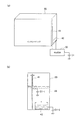
[比較例]
比較例に係るインクカートリッジを搭載したインク搭載ユニットの概略構成は、図1(a)に模式的に示すように表され、図1(a)に例示したインクカートリッジインクの検出機構は、図1(b)に模式的に示すように表される。
[Comparative example]
A schematic configuration of an ink mounting unit on which an ink cartridge according to a comparative example is mounted is represented as schematically shown in FIG. 1A. The ink cartridge ink detection mechanism illustrated in FIG. It is expressed as schematically shown in (b).
比較例に係るインク搭載ユニット10Aは、図1(a)に例示するように、例えばインク色毎に用意されたインクカートリッジ20A−1・20A−2・…・20A−Nを搭載する。また、インク搭載ユニット10Aは、各インクカートリッジ20A−1・20A−2・…・20A−Nと、プリンタ本体制御部101Aとの間の通信制御を行うインタフェース(I/F)部39Aを備える。
The
インク搭載ユニット10Aに搭載されるインクカートリッジ20Aは、図1(b)に例示するように、検出回路(ICチップ)30Aとインク出口81とプリズム部82とを備える。検出回路30Aは、印刷時やノズルクリーニング時などにインク出口81から供出されたインク29量(実際には印字ドット数)をカウントすることにより、おおよそのインク残量を推測する(ドットカウント方式)。また、検出回路30Aは、インクカートリッジ20Aの底部に部分的にプリズム状に加工されたプリズム部82を通して、視認性のあるインクに光源83から光を当て、その反射によってインクの有無を検出する(光学式)。そして、検出回路30Aは、ドットカウント方式あるいは光学式によってインク切れを検出すると、その旨をI/F部39Aを通じてプリンタ本体制御部101Aに通知する。プリンタ本体制御部101Aは、検出回路30Aからインク切れの情報を受信すると、それに呼応して、警告メッセージ、警告音等をプリンタ本体の出力部(図示省略)に出力する。
As illustrated in FIG. 1B, the
ドットカウント方式によるインク残量検出は、実際に消費されたインク量をカウントするのではなく、印字ドット数をカウントしてインク29の消費量に換算する方式であるため、誤差が生じる可能性がある。そのため、比較的余裕をもってインク29の残量を判定するため、余裕のあるインク交換が可能である(例えば、印字のカスレ等の心配がない)。その一方で、インク切れの警告が出ても、インクカートリッジ20A内にはインク29が多量に残っているといった現象が起こり、インクを使いきれない無駄が生じる可能性がある。
The ink remaining amount detection by the dot count method is not a method of counting the actually consumed ink amount, but is a method of counting the number of printed dots and converting it into the consumption amount of the
光学式によるインク残量検出では、インク切れの検出精度がよく、インク29を使いきれない無駄が生じる可能性が比較的少ないというメリットがある一方で、汚れや傷に弱く、インクカートリッジ20Aやプリズム部82に汚れや傷が生じるとインク29の有無を正確に検出できないといった現象が起こる。
Optical ink remaining amount detection has the advantages of good detection accuracy of ink shortage and relatively low possibility that waste of
また、このようなインク残量検出機能を備えた検出回路(ICチップ)30Aをインクカートリッジ20A−1・20A−2・…・20A−N毎に備えているため、インクカートリッジ20A−1・20A−2・…・20A−Nの製造コストが高くなる。
Further, since the detection circuit (IC chip) 30A having such a function of detecting the remaining amount of ink is provided for each of the
さらにまた、使用済みのインクカートリッジ20Aに対して、非純正インク29Dの詰め替えが簡単にできてしまうため、印刷系のトラブル(印字品質低下、駆動系の負荷増による故障、インク漏れなど)が発生する可能性がある。
Furthermore, since the
[第1の実施の形態]
第1の実施形態に係るインクカートリッジの概略構成は、図2(a)に模式的に例示されるように表され、図2(a)に例示したインクカートリッジインクの検出機構の概略構成は、図2(b)に模式的に例示されるように表される。
[First embodiment]
The schematic configuration of the ink cartridge according to the first embodiment is represented as schematically illustrated in FIG. 2A, and the schematic configuration of the ink cartridge ink detection mechanism illustrated in FIG. It is expressed as schematically illustrated in FIG.
第1の実施形態に係るインクカートリッジ20は、図2(a)に例示されるように、インクカートリッジ20の側面にそれぞれ敷設された全体量検出電極41と詳細量検出電極42の2種類の電極を備える。より具体的には、全体量検出電極41および詳細量検出電極42は、インクカートリッジ20の外側若しくは内側の側面に敷設されるか、またはインクカートリッジ20の外壁の側面に内蔵される。なお、全体量検出電極41および詳細量検出電極42をインクカートリッジ20の内側に敷設または外壁に内蔵する場合、好ましくは、全体量検出電極41および詳細量検出電極42がインク29に直接触れないように、インク29から所定の距離(すなわち、全体量検出電極41および詳細量検出電極42によってインク29の存在を検出するのに最低限必要な距離(例えば1〜2mm程度))を置いて敷設または内蔵すると良い。全体量検出電極41および詳細量検出電極42は、インクカートリッジ20の外部に設置された検出回路30(例えばICチップ)にそれぞれ接続される。全体量検出電極41は、インクカートリッジ20の底部付近(インク29の最小水位の高さ付近)からインクカートリッジ20の頂部付近(インク29の最大水位の高さ付近)まで縦方向に細長く敷設される。詳細量検出電極42は、比較的幅広の面積を有する電極であり、インクカートリッジ20の底部側に全体量検出電極41の幅よりも幅広く横方向に敷設される。
As illustrated in FIG. 2A, the
全体量検出電極41と詳細量検出電極42としては、例えば、静電容量方式の検出電極を用いることができ、それぞれの電極(41・42)へのインク29の接触の有無(すなわち、インク29の存在の有無)を静電容量の変化として検出するための検出電極である。検出回路30は、キャリブレーション用に基準となる基準容量C1を備え、全体量検出電極41および詳細量検出電極42のいずれか一方若しくは両方が検知した静電容量と、基準容量C1(C1−1・C1−2)とを比較して、インクカートリッジ20内のインク29の水位(すなわち、インク残量)を検出する。
As the total
全体量検出電極41は、インクカートリッジ20のインク29の大まかな水位(大まかなインク残量)をインクカートリッジ20全体にわたって検出するための電極である。詳細量検出電極42は、全体量検出電極41によって検出されたインク29の水位が、所定の閾値(例えば、インク29の最大水位の1/2、1/3、1/4など)まで低下した以降、最終的にインク切れを検出するまでの間、インクカートリッジ20内のインク29の詳細な水位(詳細なインク残量)を比較的高精度に検出するための電極である。
The total
なお、全体量検出電極41と詳細量検出電極42は、静電容量方式の検出電極の代わりに、感圧抵抗膜方式の検出電極を採用することもできる。
Note that the total
検出回路30は、インクカートリッジ20に設置する必要はなく、図10〜図14等を参照しながら後述するように、例えば、インク搭載ユニット10内に設置しても良いし、プリンタ本体100内や、外部制御装置200内に設置しても良い。
The
(第1の実施形態の変形例)
第1の実施形態の変形例に係るインクカートリッジ20の検出機構の概略構成は、図3に模式的に例示するように表される。第1の実施形態の変形例に係るインクカートリッジ20には、3段に縦積みされた詳細量検出電極42−1・42−2・42−3が敷設されている。それ以外の構成は、図2(b)に例示した第1の実施形態に係るインクカートリッジ20の検出機構の構成と同様である。
(Modification of the first embodiment)
A schematic configuration of a detection mechanism of the
なお、図3には、3段に縦積みされた詳細量検出電極42−1・42−2・42−3が敷設された例を示しているが、段数は、3段に限定されず、2段以下でも良いし、4段以上でも良い。また、縦積みに限らず、横並びに敷設されても良いし、マトリックス状や放射状に敷設されても良い。 FIG. 3 shows an example in which the detailed amount detection electrodes 42-1, 42-2, and 42-3 that are vertically stacked in three stages are laid, but the number of stages is not limited to three, Two steps or less may be used, and four steps or more may be used. Moreover, it is not limited to the vertical stacking, it may be laid side by side, or may be laid in a matrix form or a radial form.
第1の実施形態およびその変形例に係るインクカートリッジ20によれば、インクカートリッジ20に全体量検出電極41と詳細量検出電極42の2種類の電極を敷設するだけの簡単で且つ安価な仕組みで、インク29の残量を高精度に検出することができるとともに、インクカートリッジ20のコストを低減することができる。
According to the
[第2の実施の形態]
第2の実施形態に係るインクカートリッジの概略構成は、図4(a)に模式的に例示されるように表される。
[Second Embodiment]
A schematic configuration of the ink cartridge according to the second embodiment is represented as schematically illustrated in FIG.
第2の実施形態に係るインクカートリッジ20は、図4(a)に例示されるように、インクカートリッジ20の外側若しくは内側の側面および上面に敷設さえたまたはインクカートリッジ20の外壁の側面および上面に内蔵された断線検出電極43を備える。断線検出電極43は、インクカートリッジ20の外部に設置された検出回路30(例えばICチップ)に接続される。断線検出電極43は、非純正インクの詰め替えなどに起因する断線等を検出したい部分に信号ループとして敷設される。図4(a)に示した例では、断線検出電極43は、インクカートリッジ20の側面の底部付近からスタートして、インクカートリッジ20側面の頂部付近を通ってインクカートリッジ20上面の一方の端部から他方の端部付近まで延伸し、他方の端部付近に達したところで折り返して、折り返し点まで延伸してきた電極ラインと平行するように、インクカートリッジ20上面の一方を通って、インクカートリッジ20側面の頂部付近からインクカートリッジ20の側面の底部付近まで戻るように延伸する。
As illustrated in FIG. 4A, the
断線検出電極43としては、例えば、感圧抵抗膜方式の検出電極を用いることができ、断線検出電極43の断線、剥離、変形の有無などを検出するための検出電極である。検出回路30は、信号ループとして敷設された断線検出電極43の断線や剥離の有無などを検出する。
As the
なお、全体量検出電極41と詳細量検出電極42は、感圧抵抗膜方式の検出電極の代わりに、静電容量方式の検出電極を採用することもできる。また、単に断線検出電極43の断線のみを検出する場合には、単純な信号線を用いても良い。
The total
検出回路30は、インクカートリッジ20に設置する必要はなく、図10〜図14等を参照しながら後述するように、例えば、インク搭載ユニット10内に設置しても良いし、プリンタ本体100内や、外部制御装置200内に設置しても良い。
The
(第2の実施形態の変形例1)
第2の実施形態の変形例1に係るインクカートリッジ20の検出機構の概略構成は、図4(b)に模式的に例示するように表される。第2の実施形態に係るインクカートリッジ20に敷設された断線検出電極43は、インクカートリッジ20の上面において、2本のラインが直線状に平行するように敷設されていた。それに対して、第2の実施形態の変形例1に係るインクカートリッジ20に敷設された断線検出電極43では、インクカートリッジ20の上面において、平行するように敷設された2本のラインのうちの1本が櫛状に敷設されている。このように、非純正インクの詰め替えなどに起因する断線等を厳密に検出したいような部分に、断線検出電極43を櫛状に敷設することで、断線検出電極43断線、剥離、変形などを高精度に検出することができる。
(
A schematic configuration of the detection mechanism of the
なお、図4(b)に示した例では、インクカートリッジ20の上面において、平行するように敷設された断線検出電極43の2本のラインのうちの1本を櫛状にしたが、2本とも櫛状にしても良いし、インクカートリッジ20の側面に敷設する断線検出電極43を櫛状にしても良い。また、形状は、櫛状に限らず、渦巻状や螺旋状など、他の形状を用いることもできる。
In the example shown in FIG. 4B, one of the two lines of the
(第2の実施形態の変形例2)
図5は、第2の実施形態の変形例2に係るインクカートリッジ20をインク色(例えば、C(シアン)、M(マゼンタ)、Y(イエロー)、K(ブラック)、Lc(ライトシアン)、Lm(ライトマゼンタ)など)毎に複数配置した様子を模式的に例示している。図5に示す例では、インク色毎に複数配置したインクカートリッジ20毎に、外部に設置された検出回路30を接続しているため、単一の検出回路30で複数のインクカートリッジ20の検出動作を行うよりも処理時間的に有利である。例えば、プリンタ本体100の電源投入時に、インク色毎に複数配置したインクカートリッジ20の検出動作を一斉に行うことで、印刷動作を行う前に、非純正インク29Dの詰め替えの有無などを検出することができる。
(
FIG. 5 illustrates an
第2の実施形態およびその変形例1、2に係るインクカートリッジ20によれば、断線検出電極43をインクカートリッジ20の外側若しくは内側に敷設するまたはインクカートリッジ20の外壁に内蔵するだけの簡単で且つ安価な仕組みで、インクカートリッジ20に敷設された断線検出電極の断線の有無を検出することができるので、非純正インクの詰め替えの有無などを検知することができる。さらに、インクカートリッジ20のコストを低減することもできる。
According to the
[第3の実施の形態]
第3の実施形態に係るインクカートリッジの概略構成は、図6(a)に模式的に例示されるように表される。
[Third embodiment]
A schematic configuration of the ink cartridge according to the third embodiment is represented as schematically illustrated in FIG.
第3の実施形態に係るインクカートリッジ20は、図3(a)に例示されるように、インクカートリッジ20にそれぞれ敷設された全体量検出電極41と詳細量検出電極42の2種類の電極を備える。全体量検出電極41と詳細量検出電極42は、インクカートリッジ20の外部に設置された検出回路30(例えばICチップ)にそれぞれ接続される。全体量検出電極41および詳細量検出電極42は、それぞれの電極(41・42)へのインク29の接触の有無(すなわち、インク29の存在の有無)を静電容量の変化として検出するための検出電極である。
As illustrated in FIG. 3A, the
さらに、第3の実施形態に係るインクカートリッジ20は、第2の実施形態にて例示したように、インクカートリッジ20の外側若しくは内側の側面および上面に敷設されたまたはインクカートリッジ20の外壁の側面および上面に内蔵された断線検出電極43も備える。断線検出電極43は、インクカートリッジ20の外部に設置された検出回路30に接続され、非純正インクの詰め替えなどに起因する断線等を検出したい部分に信号ループとして敷設される。
Further, as illustrated in the second embodiment, the
第3の実施形態に係るインクカートリッジ20に敷設された全体量検出電極41および詳細量検出電極42の構造や機能は、第1の実施形態において例示した全体量検出電極41および詳細量検出電極42の構造や機能と同様であるため、詳細な説明を省略する。また、第3の実施形態に係るインクカートリッジ20に敷設された断線検出電極43の構造や機能は、第2の実施形態において例示した断線検出電極43の構造や機能と同様であるため、詳細な説明を省略する。
The structures and functions of the total
第3の実施形態に係るインクカートリッジ20は、インク29の残量を高精度に検出する機能と、インクカートリッジ20に敷設された断線検出電極の断線を検出する機能との双方を有する。
The
(第3の実施形態の変形例)
第3の実施形態の変形例に係るインクカートリッジ20の検出機構の概略構成は、図6(b)に模式的に例示するように表される。第3の実施形態の変形例に係るインクカートリッジ20に敷設された断線検出電極43では、第2の実施形態の変形例1と同様に、インクカートリッジ20の上面において、平行するように敷設された2本のラインのうちの1本が櫛状に敷設されている。それ以外の構成は、図6(a)に例示した第3の実施形態に係るインクカートリッジ20の検出機構の構成と同様である。
(Modification of the third embodiment)
A schematic configuration of a detection mechanism of the
第3の実施形態の変形例に係るインクカートリッジ20においても、インク29の残量を高精度に検出する機能と、インクカートリッジ20に敷設された断線検出電極の断線の有無を検出する機能の双方を有する。
Also in the
第3の実施形態およびその変形例に係るインクカートリッジ20によれば、インクカートリッジ20に全体量検出電極41と詳細量検出電極42の2種類の電極を敷設するだけの簡単で且つ安価な仕組みで、インク29の残量を高精度に検出することができるとともに、インクカートリッジ20のコストを低減することができる。さらに、第3の実施形態およびその変形例に係るインクカートリッジ20によれば、インクカートリッジ20に断線検出電極43を敷設するだけの簡単で且つ安価な仕組みで、インクカートリッジ20に敷設された断線検出電極の断線の有無を検出することができるので、非純正インクの詰め替えの有無などを検知することができる。
According to the
(検出電極)
第1〜第3の実施形態およびそれぞれの変形例に適用可能な検出電極の例は、図7に示すように表される。図7(a)全体量検出電極41と詳細量検出電極42とを備えた電極転写フィルム45の一例であり、図7(b)は、断線検出電極43を備えた電極転写フィルム45の一例であり、図7(c)は、全体量検出電極41と詳細量検出電極42と断線検出電極43とを備えた電極転写フィルム45の一例である。このような電極転写フィルム45を用いて、全体量検出電極41、詳細量検出電極42、あるいは断線検出電極43をインクカートリッジ20に転写することができる。
(Detection electrode)
Examples of detection electrodes applicable to the first to third embodiments and the respective modifications are expressed as shown in FIG. FIG. 7A is an example of an
また、図7(d)は、全体量検出電極41と詳細量検出電極42と断線検出電極43とを備えた電極剥離型シール45Aの一例である。このような電極剥離型シール45Aを用いて、全体量検出電極41、詳細量検出電極42、あるいは断線検出電極43をインクカートリッジ20に敷設することができる。
FIG. 7D is an example of an electrode
なお、第1〜第3の実施形態およびそれぞれの変形例に適用可能な検出電極としては、電極転写フィルム45や電極剥離型シール45Aに限らず、全体量検出電極41、詳細量検出電極42、あるいは断線検出電極43が形成されたフレキシブル基板、シール、テープなどを用いることもできるし、ペイント等でインクカートリッジ20に形成することもできる。
The detection electrodes applicable to the first to third embodiments and the respective modified examples are not limited to the
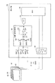
(検出回路)
第1〜第3の実施形態およびそれぞれの変形例に適用可能な検出回路30の概略ブロック構成は、図8に模式的に例示するように表される。第1〜第3の実施形態およびそれぞれの変形例に適用可能な検出回路30は、全体量検出電極41および詳細量検出電極42のいずれか一方と基準容量C1とを選択的に切り替えて容量・電圧変換回路32に接続する複数のスイッチSW−1・SW−2・SW−3を備えるスイッチ群と、スイッチ群の出力側に接続された容量・電圧変換回路32と、容量・電圧変換回路32の出力に接続されたアナログ/デジタル(A/D)変換器33と、断線検出電極43に接続されたアナログフロントエンド(AFE:Analog Front End)34と、A/D変換器33の出力およびAFE34の出力に接続されたマイクロコントローラユニット(MCU:Micro-Controller Unit)35とを備える。
(Detection circuit)
A schematic block configuration of the
容量・電圧変換回路32は、容量C1を基準容量C1として、スイッチ群によって選択的に接続された全体量検出電極41と詳細量検出電極42のいずれか一方若しくは両方を測定電極として入力し、演算増幅器OPの反転入力に接続された容量C2と、演算増幅器OPの反転入力と出力との間に接続された容量C3との比により変位を検出する。容量・電圧変換回路32の出力は、A/D変換器33によってデジタル信号に変換されて、MCU35に供給され、インクカートリッジ20内のインク29の水位(すなわち、インク残量)の値として検知される。
The capacitance /
その一方で、断線検出電極43に接続されたAFE34は、断線検出電極43の断線等の有無を検出して、検出結果をMCU35に供給する。
On the other hand, the
検出回路30は、インク切れやインクカートリッジ20に敷設された断線検出電極の断線の有無などを検出すると、その旨をプリンタ本体制御部101などに通知する。
When the
(インク搭載ユニット)
第1〜第3の実施形態およびそれぞれの変形例に適用可能なインクカートリッジ20を搭載したインク搭載ユニット10の概略構成は、図9に模式的に例示するように表される。
(Ink mounted unit)
A schematic configuration of the
インク搭載ユニット10は、例えばインク色(C、M、Y、K、Lc、Lmなど)毎に用意された最大N個(ここで、Nは1以上の整数)のインクカートリッジ20を搭載可能に構成され、N個のインクカートリッジ20のそれぞれに敷設された全体量検出電極41、詳細量検出電極42、および断線検出電極43に接続するN個の検出回路30(30−1・30−2・…・30−(N−2)・30−(N−1)・30−N)と、各検出回路30(30−1・30−2・…・30−(N−2)・30−(N−1)・30−N)と、外部のプリンタ本体制御部101などとの間の通信制御を行うI/F部39とを備える。
The
なお、図9に示した例では、インクカートリッジ20毎に1つの検出回路30を設けている(インクカートリッジ20に1対1に対応する)が、これに限定されず、1つの検出回路30で2つのインクカートリッジ20、1つの検出回路30で3つのインクカートリッジ20、…、1つの検出回路30で(N−1)個のインクカートリッジ20、1つの検出回路30でN個のインクカートリッジ20に対応しても良い。
In the example shown in FIG. 9, one
なお、インクカートリッジ20のサイズは、単一であるとは限らず、例えば、K(ブラック)のインク29を入れるインクカートリッジ20だけが大きいという場合や、Lc(ライトシアン)やLm(ライトマゼンタ)のインク29を入れるインクカートリッジ20だけが小さいという場合もある。
Note that the size of the
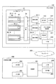
(プリントシステム(第1の態様))
図10は、第1〜第3の実施形態およびそれぞれの変形例に適用可能なプリントシステムの第1の態様の概略ブロック構成を模式的に例示する。
(Print system (first aspect))
FIG. 10 schematically illustrates a schematic block configuration of the first aspect of the print system applicable to the first to third embodiments and the respective modifications.
第1の態様のプリントシステムは、図10に例示するように、プリンタ本体100と、外部制御装置200とを備え、プリンタ本体100と外部制御装置200とは、例えばクラウドネットワークなどの有線/無線のネットワーク300を介して、あるいは相互に直接的に接続される。
As illustrated in FIG. 10, the print system according to the first aspect includes a printer
プリンタ本体100は、インク搭載ユニット10と、プリンタ本体制御部101と、入力部102と、出力部103と、記憶部104と、I/F部109とを備える。
The printer
プリンタ本体制御部101は、入力部102から入力された設定値や閾値などをインク搭載ユニット10に送信したり、記憶部104に格納したりする。また、インク搭載ユニット10から送信されるインク切れやインクカートリッジ20に敷設された断線検出電極の断線の有無などの情報を受信すると、それに呼応して、警告メッセージや警告音等を、出力部103に出力したり、I/F部109を通じて、外部制御装置200に通知したりすることができる。
The printer main
インク搭載ユニット10は、図9にも例示したように、最大N個(ここで、Nは1以上の整数)のインクカートリッジ20を搭載可能に構成され、N個のインクカートリッジ20(20−1・20−2・…・20−N)毎に全体量検出電極41、詳細量検出電極42、および断線検出電極43に接続するN個の検出回路30(30−1・30−2・…・30−N)と、各検出回路30(30−1・30−2・…・30−N)と、プリンタ本体制御部101との間の通信制御を行うI/F部39とを備える。インク搭載ユニット10には、第1〜第3の実施形態およびそれぞれの変形例に係るインクカートリッジ20を適宜搭載することができる。
As illustrated in FIG. 9, the
第1の態様のプリントシステムでは、インク色毎に複数配置したN個のインクカートリッジ20毎に、検出回路30を接続しているため、単一の検出回路30で複数のインクカートリッジ20の検出動作を行うよりも処理時間的に有利である。
In the print system according to the first aspect, since the
外部制御装置200は、例えば、パーソナルコンピュータ、タブレットコンピュータ、スマートフォンなどを用いて構成することができ、制御部201と、入力部202と、出力部203と、記憶部204と、I/F部209とを備える。制御部201は、入力部202から入力された設定値や閾値などをプリンタ本体100に送信したり、記憶部204に格納したりする。また、プリンタ本体100から送信されるインク切れやインクカートリッジ20に敷設された断線検出電極の断線の有無などの情報を受信すると、それに呼応して、警告メッセージや警告音等を、出力部203に出力することができる。
The
(プリントシステム(第2の態様))
図11は、第1〜第3の実施形態およびそれぞれの変形例に適用可能なプリントシステムの第2の態様の概略ブロック構成を模式的に例示する。
(Print system (second aspect))
FIG. 11 schematically illustrates a schematic block configuration of a second aspect of the print system applicable to the first to third embodiments and the respective modifications.
図11に例示するように、第2の態様のプリントシステムでは、インク搭載ユニット10は、N個のインクカートリッジ20−1・20−2・…・20−Nにそれぞれ対応するN個の検出回路30−1・30−2・…・30−Nの代わりに、N個のインクカートリッジ20−1・20−2・…・20−Nに対応する単一の検出回路30を備える。それ以外の各部の構成は、第1の態様のプリントシステムの構成と同様である。
As illustrated in FIG. 11, in the printing system of the second aspect, the
第2の態様のプリントシステムでは、単一の検出回路30で複数のインクカートリッジ20の検出動作を行うため、検出回路30のコストを抑えることができる。
In the printing system of the second aspect, since the detection operation of the plurality of
(プリントシステム(第3の態様))
図12は、第1〜第3の実施形態およびそれぞれの変形例に適用可能なプリントシステムの第3の態様の概略ブロック構成を模式的に例示する。
(Print System (Third Aspect))
FIG. 12 schematically illustrates a schematic block configuration of a third aspect of the print system applicable to the first to third embodiments and the respective modifications.
図12に例示するように、第3の態様のプリントシステムでは、N個のインクカートリッジ20−1・20−2・…・20−Nに対応する単一の検出回路30を、インク搭載ユニット10が備える代わりに、プリンタ本体100が備える。それ以外の各部の構成は、第2の態様のプリントシステムの構成と同様である。
As illustrated in FIG. 12, in the printing system of the third aspect, a
第3の態様のプリントシステムでは、複数のインクカートリッジ20の検出動作を行う単一の検出回路30をプリンタ本体100が備えるため、インク搭載ユニット10のコストを抑えることができる。
In the printing system of the third aspect, since the printer
(プリントシステム(第4の態様))
図13は、第1〜第3の実施形態およびそれぞれの変形例に適用可能なプリントシステムの第4の態様の概略ブロック構成を模式的に例示する。
(Print system (fourth aspect))
FIG. 13 schematically illustrates a schematic block configuration of a fourth aspect of the print system applicable to the first to third embodiments and the respective modifications.
図13に例示するように、第4の態様のプリントシステムでは、N個のインクカートリッジ20−1・20−2・…・20−Nにそれぞれ対応するN個の検出回路30−1・30−2・…・30−Nを、インク搭載ユニット10が備える代わりに、プリンタ本体100が備える。それ以外の各部の構成は、第1の態様のプリントシステムの構成と同様である。
As illustrated in FIG. 13, in the printing system according to the fourth aspect, N detection circuits 30-1 and 30-respectively corresponding to the N ink cartridges 20-1, 20-2,. ... 30-N are provided in the printer
第4の態様のプリントシステムでは、複数のインクカートリッジ20の検出動作をそれぞれ行うにそれぞれ対応するN個の検出回路30−1・30−2・…・30−Nをプリンタ本体100が備えるため、インク搭載ユニット10のコストを抑えることができる。また、単一の検出回路30で複数のインクカートリッジ20の検出動作を行うよりも処理時間的に有利である。
In the printing system of the fourth aspect, the printer
(プリントシステム(第5の態様))
図14は、第1〜第3の実施形態およびそれぞれの変形例に適用可能なプリントシステムの第5の態様の概略ブロック構成を模式的に例示する。
(Print system (fifth aspect))
FIG. 14 schematically illustrates a schematic block configuration of a fifth aspect of the print system applicable to the first to third embodiments and the respective modifications.
図14に例示するように、第5の態様のプリントシステムでは、N個のインクカートリッジ20−1・20−2・…・20−Nに対応する単一の検出回路30を、インク搭載ユニット10やプリンタ本体100が備える代わりに、外部制御装置200が備える。それ以外の各部の構成は、第1〜4の態様のプリントシステムの構成と同様である。
As illustrated in FIG. 14, in the printing system of the fifth aspect, a
第4の態様のプリントシステムでは、複数のインクカートリッジ20の検出動作を行う単一の検出回路30を外部制御装置200が備えるため、インク搭載ユニット10やプリンタ本体100のコストを抑えることができる。
In the printing system of the fourth aspect, since the
(比較例におけるインク残量検出方法)
図15は、比較例におけるインク残量検出方法の処理手順を概略的に例示する。
(Ink remaining amount detection method in comparative example)
FIG. 15 schematically illustrates the processing procedure of the remaining ink amount detection method in the comparative example.
例えば、プリンタ本体100の電源を入れると、処理を開始する(ステップS101)。
For example, when the printer
ステップS102において、プリンタ本体100などから印刷命令が入力されると、ステップS103において、印刷の内容に応じて印刷量やインク29の混合量などの指示情報が、プリンタ本体100からインクカートリッジ20Aの検出回路30Aに送信される。
In step S102, when a print command is input from the printer
印刷処理が開始されると、ステップS104−1において、インクカートリッジ20Aの検出回路30Aは、インク出口81から供出されるインク29量(実際には印字ドット数)をカウントすることにより、おおよそのインク残量を推測する(ドットカウント方式)。検出値(カウント値)は、検出回路30A内の記憶部(図示省略)に記憶される。
When the printing process is started, in step S104-1, the
一方で、ステップS104−2において、インクカートリッジ20Aの検出回路30Aは、インクカートリッジ20Aの底部に部分的にプリズム状に加工されたプリズム部82を通して、視認性のあるインクに光源83から光を当て、その反射によってインク29の残量(有無)を検出する(光学式)。検出値(残量値)は、検出回路30A内の記憶部(図示省略)に記憶される。
On the other hand, in step S104-2, the
次に、ステップS105において、検出回路30Aは、ステップS104−1およびステップS104−2での検出値と、予め設定された閾値とを比較し、検出値が閾値以上であれば、インク29の残量が十分にあると判断して、ステップS102に戻る。
Next, in step S105, the
ステップS105において、検出値が閾値を下回れば、インク切れになったものと判断して、インク切れの情報をプリンタ本体100の制御部などに通知する。
In step S105, if the detected value falls below the threshold value, it is determined that the ink has run out, and information about the ink running out is notified to the control unit of the printer
(実施の形態におけるインク残量検出方法)
図16は、第1〜第3の実施形態およびそれぞれの変形例に適用可能なインク残量検出方法の処理手順を概略的に例示する。
(Ink remaining amount detection method in the embodiment)
FIG. 16 schematically illustrates a processing procedure of an ink remaining amount detection method applicable to the first to third embodiments and the respective modifications.
例えば、プリンタ本体100の電源を入れると、処理を開始する(ステップS201)。
For example, when the printer
印刷処理を始める前に、ステップS202において、プリンタ本体100の入力部102あるいは外部制御装置200の入力部202などからインクカートリッジ20毎(インク29の色毎)に第1の閾値や第2の閾値を設定し、プリンタ本体100の記憶部104あるいは外部制御装置200の記憶部204に格納しておく。
Before starting the printing process, in step S202, the first threshold value and the second threshold value are set for each ink cartridge 20 (for each color of ink 29) from the
ステップS203において、プリンタ本体100の入力部102あるいは外部制御装置200の入力部202などから印刷命令が入力されると、ステップS204において、印刷の内容に応じて印刷量やインク29の混合量などの指示情報が、プリンタ本体100あるいは外部制御装置200から、インク搭載ユニット10、プリンタ本体100、あるいは外部制御装置200の検出回路30に送信される。
In step S203, when a print command is input from the
印刷処理が始まると、ステップS205において、検出回路30は、全体量検出電極41を用いて、インクカートリッジ20のインク29の大まかな水位(大まかなインク残量)を検出する。
When the printing process starts, in step S205, the
ステップS206において、検出回路30は、ステップS205での検出値と、予め設定されて記憶された第1の閾値(例えば、インク29の最大水位の1/2、1/3、若しくは1/4など)とを比較する。比較の結果、ステップS205での検出値が第1の閾値以上(例えば、インク29が1/2以上、1/3以上、または1/4以上残っているなど)であれば、インク29の残量が十分にあると判断して、ステップS203に戻る。
In step S206, the
ステップS206での比較の結果、ステップS205の検出値が第1の閾値を下回れば(例えば、インク29が1/2以下、1/3以下、または1/4以下に減少しているなど)であれば、インク29の残量が少なくなりつつあると判断して、ステップS207に進む。
As a result of the comparison in step S206, if the detection value in step S205 is below the first threshold (for example,
ステップS207において、検出回路30は、詳細量検出電極42を用いて、インクカートリッジ20内のインク29の詳細な水位(詳細なインク残量)を高精度に検出する。
In step S207, the
ここで、図17(a)を参照すると、全体量検出電極41の幅aよりも幅広である幅bをもつ詳細量検出電極42は、全体量検出電極41の検出精度のb/a倍の検出精度でインク29の水位を検出することができる。より具体的には、全体量検出電極41の幅が1mmで、詳細量検出電極42の幅が10mmであれば、詳細量検出電極42は、全体量検出電極41の検出精度の10/1倍(=10倍)の検出精度でインク29の水位を検出することができる。
Here, referring to FIG. 17A, the detailed
ステップS208において、検出回路30は、ステップS207での検出値と、予め設定されて記憶された第2の閾値(例えば、インク29の最大水位の1%など)とを比較する。比較の結果、ステップS207での検出値が第2の閾値以上であれば、インク29の残量がまだあると判断して、ステップS203に戻る。
In step S <b> 208, the
ステップS208での比較の結果、ステップS207の検出値が第2の閾値を下回れば(例えば、インク29が1%以下に減少しているなど)であれば、インク29切れであると判断して、ステップS209に進み、検出回路30は、インク切れの情報をプリンタ本体100あるいは外部制御装置200に通知する。
As a result of the comparison in step S208, if the detected value in step S207 falls below the second threshold (for example,
なお、ステップS205〜S208の検出処理を行うタイミングは、印刷処理時のみに限らず、入力部102、202からの設定によって、定期的に行っても良いし、電源投入時、インク交換時、イベント発生時などに行っても良いし、複数の条件を組み合わせたタイミングで行っても良い。
Note that the timing of performing the detection processing in steps S205 to S208 is not limited to the time of printing processing, but may be periodically performed according to settings from the
また、実施の形態におけるインク残量検出方法は、コンピュータプログラムとして定義することができ、インク搭載ユニット10、プリンタ本体100、あるいは外部制御装置200の検出回路30内で動作させることもできる。
Further, the ink remaining amount detection method in the embodiment can be defined as a computer program, and can be operated in the
以上説明したように、第1〜第3の実施形態およびその変形例によれば、インクカートリッジ20に全体量検出電極41と詳細量検出電極42の2種類の電極を敷設するだけの簡単で且つ安価な仕組みで、インク29の残量を高精度に検出することができるとともに、インクカートリッジ20のコストを低減することができる。さらに、断線検出電極43をインクカートリッジ20の外側若しくは内側に敷設する若しくはインクカートリッジ20の外壁に内蔵するだけの簡単で且つ安価な仕組みで、インクカートリッジ20に敷設された断線検出電極の断線の有無を検出することができるので、非純正インクの詰め替えの有無などを検知することができる。また、全体量検出電極41と詳細量検出電極42と、断線検出電極43とを組み合わせて、インクカートリッジ20に敷設することもできる。
As described above, according to the first to third embodiments and the modifications thereof, it is simple that only two types of electrodes, that is, the total
[その他の実施の形態]
上記のように、第1〜第3の実施の形態およびその変形例について記載したが、この開示の一部をなす論述および図面は例示的なものであり、限定するものであると理解すべきではない。この開示から当業者には様々な代替実施の形態、実施例および運用技術が明らかとなろう。
[Other embodiments]
As described above, the first to third embodiments and the modifications thereof have been described. However, it should be understood that the descriptions and drawings constituting a part of this disclosure are illustrative and limiting. is not. From this disclosure, various alternative embodiments, examples and operational techniques will be apparent to those skilled in the art.
例えば、第1〜第3の実施の形態およびその変形例では、プリンタ用のインクの場合について説明したが、静電容量方式や感圧抵抗膜方式で検出可能な流体の残量検知などにも同様に適用することができる。 For example, in the first to third embodiments and the modifications thereof, the case of ink for a printer has been described. However, it is also possible to detect the remaining amount of fluid that can be detected by a capacitance method or a pressure-sensitive resistance film method. The same can be applied.
このように、ここでは記載していない様々な実施の形態などを含む。 As described above, various embodiments that are not described herein are included.
第1〜第3の実施の形態およびその変形例は、印刷機、複写機、複合機、小売店のレジ、飲食店の食券機、駅や空港の券売機など様々な応用分野に適用可能である。 The first to third embodiments and modifications thereof can be applied to various application fields such as printing machines, copiers, multifunction machines, cash registers in retail stores, restaurant ticket machines in restaurants, and ticket machines in stations and airports. is there.
10、10A…インク搭載ユニット
20、20−1、20−2、20−N、20A−1、20A−2、20A−N…インクカートリッジ
29…インク
29D…非純正インク
30、30−1、30−2、30−(N−2)、30−(N−1)、30−N、30A…検出回路(ICチップ)
32…容量・電圧変換回路
33…アナログ/デジタル(A/D)変換器
34…アナログフロントエンド(AFE)
35…マイクロコントローラユニット(MCU)
39、39A、109、209…インタフェース(I/F)部
41…全体量検出電極
42、42−1、42−2、42−3…詳細量検出電極
43…断線検出電極
45…電極転写フィルム
45A…電極剥離型シール
81…インク出口
82…プリズム部
100、100A…プリンタ本体
101、101A…プリンタ本体制御部
102、201…入力部
103、203…出力部
104、204…記憶部
201…制御部
C1…基準容量
C2、C3…容量
OP…演算増幅器
SW−1・SW−2・SW−3…スイッチ
10, 10A ...
32 ... Capacitance /
35 ... Microcontroller unit (MCU)
39, 39A, 109, 209 ... interface (I / F)
Claims (17)
前記インクカートリッジに敷設されるとともに、前記インクカートリッジの外部に設置された検出回路にそれぞれ接続された、前記インクカートリッジ全体にわたって前記インクの存在の有無を検出するための全体量検出電極と前記全体量検出電極を用いた前記インクの存在の有無の検出よりも詳細に前記インクの存在の有無を検出するための詳細量検出電極と、
前記インクカートリッジに信号ループとして敷設されるとともに、前記検出回路に接続された、前記信号ループの断線の有無を検出するための断線検出電極と
を備え、
前記検出回路は、前記全体量検出電極が検出した前記インクの存在の有無から前記インクカートリッジ全体にわたって前記インクの水位を検出し、前記詳細量検出電極が検出した前記インクの存在の有無から、前記全体量検出電極を用いた前記水位の検出よりも詳細に前記インクの水位を検出するとともに、前記断線検出電極を用いて前記断線検出電極の断線の有無を検出することを特徴とするインクカートリッジ。 An ink cartridge for containing ink,
While being laid on the ink cartridge, the respectively connected externally placed a detection circuit of the ink cartridge, the entire amount detecting electrode and the total amount for detecting the presence or absence of the ink throughout the ink cartridge A detailed amount detection electrode for detecting the presence or absence of the ink in more detail than the detection of the presence or absence of the ink using the detection electrode ;
A disconnection detection electrode for detecting the presence or absence of disconnection of the signal loop, which is laid as a signal loop in the ink cartridge and connected to the detection circuit ;
The detection circuit detects the water level of the ink throughout the ink cartridge from the presence or absence of the ink detected by the total amount detection electrode, and from the presence or absence of the ink detected by the detailed amount detection electrode, detects the water level of the ink in more detail than detection of the water level using the entire amount detection electrodes, the ink cartridge characterized that you detect the presence or absence of disconnection of the disconnection detection electrode with the disconnection detection electrode .
基準容量と、 Reference capacity,
前記全体量検出電極および前記詳細量検出電極のいずれか一方若しくは両方が検知した前記静電容量と、前記基準容量の静電容量とを比較して、前記インクカートリッジ内の前記インクの水位を電圧値として検出する容量・電圧変換回路と、 The capacitance detected by one or both of the total amount detection electrode and the detailed amount detection electrode is compared with the reference capacitance, and the water level of the ink in the ink cartridge is determined as a voltage. Capacitance / voltage conversion circuit to detect as a value,
前記容量・電圧変換回路の出力に接続され、前記電圧値をデジタル信号に変換するアナログ/デジタル変換器と、 An analog / digital converter connected to the output of the capacitance / voltage conversion circuit for converting the voltage value into a digital signal;
前記アナログ/デジタル変換器の出力に接続され、前記デジタル信号を前記インクの水位値として入力するマイクロコントローラユニットと、 A microcontroller unit connected to the output of the analog / digital converter and inputting the digital signal as a water level value of the ink;
前記インクカートリッジに信号ループとして敷設されるとともに、前記信号ループの断線の有無を検出するための断線検出電極に接続されるとともに、前記断線検出電極の断線の有無を検出して、検出結果を前記マイクロコントローラユニットに供給するアナログフロントエンドと The ink cartridge is laid as a signal loop, connected to a disconnection detection electrode for detecting the presence or absence of a disconnection of the signal loop, and the detection result is detected by detecting the presence or absence of disconnection of the disconnection detection electrode. Analog front end to supply to the microcontroller unit
を備えることを特徴とする検出回路。 A detection circuit comprising:
前記N個のインクカートリッジのそれぞれに敷設された全体量検出電極および詳細量検出電極に接続する請求項9または10に記載の検出回路と、 The detection circuit according to claim 9 or 10, wherein the detection circuit is connected to an entire amount detection electrode and a detailed amount detection electrode laid on each of the N ink cartridges.
前記検出回路と外部との間の通信制御を行うインタフェース部と An interface unit for controlling communication between the detection circuit and the outside;
を備えることを特徴とするインク搭載ユニット。 An ink mounting unit comprising:
前記インク搭載ユニットから送信されるインク切れやインクカートリッジに敷設された前記断線検出電極の断線の有無の情報を受信すると、警告メッセージや警告音を、出力部に出力するプリンタ本体制御部と A printer main body control unit that outputs a warning message and a warning sound to the output unit upon receiving information on whether or not there is a lack of ink transmitted from the ink mounting unit or a disconnection of the disconnection detection electrode installed in the ink cartridge;
を備えることを特徴とするプリンタ。 A printer comprising:
前記N個のインクカートリッジのそれぞれに敷設された全体量検出電極および詳細量検出電極に接続する請求項9または10に記載の検出回路と、 The detection circuit according to claim 9 or 10, wherein the detection circuit is connected to an entire amount detection electrode and a detailed amount detection electrode laid on each of the N ink cartridges.
前記インク搭載ユニットから送信されるインク切れやインクカートリッジに敷設された前記断線検出電極の断線の有無の情報を受信すると、警告メッセージや警告音を、出力部に出力するプリンタ本体制御部と A printer main body control unit that outputs a warning message and a warning sound to the output unit upon receiving information on whether or not there is a lack of ink transmitted from the ink mounting unit or a disconnection of the disconnection detection electrode installed in the ink cartridge;
を備えることを特徴とするプリンタ。 A printer comprising:
前記プリンタと、ネットワークを介して、あるいは相互に直接的に接続された外部制御装置と The printer and an external control device directly connected to each other via a network
を備え、 With
前記プリンタは、前記インク搭載ユニットから送信される送信されるインク切れやインクカートリッジに敷設された前記断線検出電極の断線の有無の情報を受信すると、警告メッセージや警告音を、前記外部制御装置に通知することを特徴とするプリントシステム。 The printer receives a warning message and a warning sound to the external control device when receiving information on whether or not there is a lack of ink transmitted from the ink mounting unit or a breakage of the breakage detection electrode laid on the ink cartridge. A printing system characterized by notification.
前記全体量検出電極が検出した前記インクの存在の有無から、前記インクカートリッジの前記インクの水位を前記検出回路が検出するステップと、 The detection circuit detecting the water level of the ink in the ink cartridge from the presence or absence of the ink detected by the total amount detection electrode;
前記全体量検出電極を用いて検出した検出値が予め設定された第1の閾値を下回る場合、前記詳細量検出電極が検出した前記インクの存在の有無から、前記インクカートリッジ内の前記インクの水位を、前記全体量検出電極を用いた前記水位の検出よりも詳細に前記検出回路が検出するステップと、 When the detection value detected using the total amount detection electrode falls below a preset first threshold value, the ink level in the ink cartridge is determined from the presence or absence of the ink detected by the detailed amount detection electrode. The step of detecting by the detection circuit in more detail than the detection of the water level using the total amount detection electrode,
前記詳細量検出電極を用いて検出した検出値が予め設定された第2の閾値を下回る場合、インク切れの情報を前記検出回路が外部に通知するステップと、 When the detection value detected using the detailed amount detection electrode is lower than a preset second threshold, the detection circuit notifies the outside of the ink out information;
前記断線検出電極を用いて、前記断線検出電極の断線の有無を前記検出回路が検出するステップと、 The detection circuit detects the presence or absence of disconnection of the disconnection detection electrode using the disconnection detection electrode;
前記断線検出電極の断線を検出した場合、前記断線検出電極の断線の情報を前記検出回路が外部に通知するステップと A step of notifying the detection circuit of the disconnection information of the disconnection detection electrode to the outside when the disconnection of the disconnection detection electrode is detected;
を有することを特徴とするインク残量検出方法。 A method for detecting the remaining amount of ink.
Priority Applications (1)
| Application Number | Priority Date | Filing Date | Title |
|---|---|---|---|
| JP2015111104A JP6560907B2 (en) | 2015-06-01 | 2015-06-01 | Ink cartridge, detection circuit, ink mounting unit, printer, print system, and ink remaining amount detection method |
Applications Claiming Priority (1)
| Application Number | Priority Date | Filing Date | Title |
|---|---|---|---|
| JP2015111104A JP6560907B2 (en) | 2015-06-01 | 2015-06-01 | Ink cartridge, detection circuit, ink mounting unit, printer, print system, and ink remaining amount detection method |
Publications (2)
| Publication Number | Publication Date |
|---|---|
| JP2016221859A JP2016221859A (en) | 2016-12-28 |
| JP6560907B2 true JP6560907B2 (en) | 2019-08-14 |
Family
ID=57746904
Family Applications (1)
| Application Number | Title | Priority Date | Filing Date |
|---|---|---|---|
| JP2015111104A Expired - Fee Related JP6560907B2 (en) | 2015-06-01 | 2015-06-01 | Ink cartridge, detection circuit, ink mounting unit, printer, print system, and ink remaining amount detection method |
Country Status (1)
| Country | Link |
|---|---|
| JP (1) | JP6560907B2 (en) |
Families Citing this family (2)
| Publication number | Priority date | Publication date | Assignee | Title |
|---|---|---|---|---|
| CN109605941B (en) | 2019-01-30 | 2020-03-10 | 北海绩迅电子科技有限公司 | Inner container ink box and processing method thereof |
| EP3991974A4 (en) * | 2019-06-28 | 2023-07-12 | Zhuhai Ninestar Management Co., Ltd. | Chip of ink container and ink container |
Family Cites Families (5)
| Publication number | Priority date | Publication date | Assignee | Title |
|---|---|---|---|---|
| JPH1034953A (en) * | 1996-07-22 | 1998-02-10 | Matsushita Electric Ind Co Ltd | Detector for residual quantity of ink |
| US6155664A (en) * | 1998-06-19 | 2000-12-05 | Lexmark International, Inc. | Off-carrier inkjet print supply with memory |
| JP2000263810A (en) * | 1999-03-15 | 2000-09-26 | Canon Inc | Recording apparatus and ink residual amount detecting method |
| JP5133667B2 (en) * | 2007-02-23 | 2013-01-30 | エスアイアイ・プリンテック株式会社 | Residual amount detection sensor and ink jet printer using the same |
| JP6136100B2 (en) * | 2012-04-06 | 2017-05-31 | 凸版印刷株式会社 | ink cartridge |
-
2015
- 2015-06-01 JP JP2015111104A patent/JP6560907B2/en not_active Expired - Fee Related
Also Published As
| Publication number | Publication date |
|---|---|
| JP2016221859A (en) | 2016-12-28 |
Similar Documents
| Publication | Publication Date | Title |
|---|---|---|
| US20140368855A1 (en) | Image forming apparatus, method for controlling the same, and program | |
| JP6560907B2 (en) | Ink cartridge, detection circuit, ink mounting unit, printer, print system, and ink remaining amount detection method | |
| JP4678047B2 (en) | Image forming apparatus, paper supply support method, and control program | |
| JPH11314375A (en) | Residual quantity detector of ink in ink cartridge | |
| US10308034B2 (en) | Liquid container, liquid remaining amount detection circuit of liquid container, liquid remaining amount detection method, liquid container identification method, ink mounting unit, printer, and print system | |
| CN104427163B (en) | Print system | |
| JP2017200143A (en) | Image forming apparatus | |
| US7905568B2 (en) | Liquid property detection device, liquid container, image forming device, and liquid property detection method | |
| JP6093616B2 (en) | Image forming apparatus | |
| CN106527089B (en) | Image forming apparatus and consumable product management method | |
| JP2010001147A (en) | Image forming device, paper sheet supply support method, and control program | |
| JP2014168939A (en) | Image formation device | |
| JP2014097589A (en) | Electronic equipment | |
| CN104076633A (en) | Image formation device and control method | |
| JP2013235190A (en) | Display system, electric device and image formation device | |
| KR20180018983A (en) | Touch display device including touch driving interated circuit and operation method of touch driving integrated circuit | |
| JPH09169118A (en) | Ink jet printer | |
| US8625123B2 (en) | Image forming system, management apparatus, and non-transitory computer readable medium | |
| US6963699B1 (en) | Method and system for providing an out of paper indication by a printer | |
| JP6021443B2 (en) | Electronics | |
| KR102647070B1 (en) | Recording apparatus and control method | |
| JP2006221426A (en) | Network system for managing consumable goods | |
| JP6540624B2 (en) | Image forming apparatus and image forming system | |
| JP2006113220A5 (en) | ||
| CN113840734B (en) | Selectable fill modes for a printing device having a reservoir fillable from an external colorant supply |
Legal Events
| Date | Code | Title | Description |
|---|---|---|---|
| A621 | Written request for application examination |
Free format text: JAPANESE INTERMEDIATE CODE: A621 Effective date: 20180521 |
|
| A977 | Report on retrieval |
Free format text: JAPANESE INTERMEDIATE CODE: A971007 Effective date: 20190213 |
|
| A131 | Notification of reasons for refusal |
Free format text: JAPANESE INTERMEDIATE CODE: A131 Effective date: 20190319 |
|
| A521 | Request for written amendment filed |
Free format text: JAPANESE INTERMEDIATE CODE: A523 Effective date: 20190515 |
|
| TRDD | Decision of grant or rejection written | ||
| A01 | Written decision to grant a patent or to grant a registration (utility model) |
Free format text: JAPANESE INTERMEDIATE CODE: A01 Effective date: 20190709 |
|
| A61 | First payment of annual fees (during grant procedure) |
Free format text: JAPANESE INTERMEDIATE CODE: A61 Effective date: 20190722 |
|
| R150 | Certificate of patent or registration of utility model |
Ref document number: 6560907 Country of ref document: JP Free format text: JAPANESE INTERMEDIATE CODE: R150 |
|
| R250 | Receipt of annual fees |
Free format text: JAPANESE INTERMEDIATE CODE: R250 |
|
| LAPS | Cancellation because of no payment of annual fees |