JP6560675B2 - Direct exhaust gas recirculation system - Google Patents
Direct exhaust gas recirculation system Download PDFInfo
- Publication number
- JP6560675B2 JP6560675B2 JP2016537060A JP2016537060A JP6560675B2 JP 6560675 B2 JP6560675 B2 JP 6560675B2 JP 2016537060 A JP2016537060 A JP 2016537060A JP 2016537060 A JP2016537060 A JP 2016537060A JP 6560675 B2 JP6560675 B2 JP 6560675B2
- Authority
- JP
- Japan
- Prior art keywords
- exhaust gas
- exhaust
- manifold
- gas recirculation
- egr
- Prior art date
- Legal status (The legal status is an assumption and is not a legal conclusion. Google has not performed a legal analysis and makes no representation as to the accuracy of the status listed.)
- Active
Links
- 239000007789 gas Substances 0.000 claims description 174
- 238000002485 combustion reaction Methods 0.000 claims description 97
- 238000000034 method Methods 0.000 claims description 62
- 239000000203 mixture Substances 0.000 claims description 30
- 239000012530 fluid Substances 0.000 claims description 26
- 238000004891 communication Methods 0.000 claims description 24
- 239000000446 fuel Substances 0.000 claims description 24
- 239000003054 catalyst Substances 0.000 claims description 14
- 238000002407 reforming Methods 0.000 claims description 11
- 238000011144 upstream manufacturing Methods 0.000 claims description 6
- QVGXLLKOCUKJST-UHFFFAOYSA-N atomic oxygen Chemical compound [O] QVGXLLKOCUKJST-UHFFFAOYSA-N 0.000 claims description 5
- 238000001816 cooling Methods 0.000 claims description 5
- 239000001257 hydrogen Substances 0.000 claims description 5
- 229910052739 hydrogen Inorganic materials 0.000 claims description 5
- 239000001301 oxygen Substances 0.000 claims description 5
- 229910052760 oxygen Inorganic materials 0.000 claims description 5
- UGFAIRIUMAVXCW-UHFFFAOYSA-N Carbon monoxide Chemical compound [O+]#[C-] UGFAIRIUMAVXCW-UHFFFAOYSA-N 0.000 claims description 4
- 229910002091 carbon monoxide Inorganic materials 0.000 claims description 4
- UFHFLCQGNIYNRP-UHFFFAOYSA-N Hydrogen Chemical compound [H][H] UFHFLCQGNIYNRP-UHFFFAOYSA-N 0.000 claims description 3
- 238000002347 injection Methods 0.000 claims description 3
- 239000007924 injection Substances 0.000 claims description 3
- 239000004215 Carbon black (E152) Substances 0.000 claims description 2
- 229930195733 hydrocarbon Natural products 0.000 claims description 2
- 150000002430 hydrocarbons Chemical class 0.000 claims description 2
- 238000002156 mixing Methods 0.000 claims description 2
- 238000010586 diagram Methods 0.000 description 9
- 230000000670 limiting effect Effects 0.000 description 6
- VNWKTOKETHGBQD-UHFFFAOYSA-N methane Chemical compound C VNWKTOKETHGBQD-UHFFFAOYSA-N 0.000 description 6
- 238000005086 pumping Methods 0.000 description 6
- 239000003949 liquefied natural gas Substances 0.000 description 5
- 230000002829 reductive effect Effects 0.000 description 5
- GQPLMRYTRLFLPF-UHFFFAOYSA-N Nitrous Oxide Chemical compound [O-][N+]#N GQPLMRYTRLFLPF-UHFFFAOYSA-N 0.000 description 4
- 238000009833 condensation Methods 0.000 description 3
- 230000005494 condensation Effects 0.000 description 3
- XLYOFNOQVPJJNP-UHFFFAOYSA-N water Chemical compound O XLYOFNOQVPJJNP-UHFFFAOYSA-N 0.000 description 3
- 230000006835 compression Effects 0.000 description 2
- 238000007906 compression Methods 0.000 description 2
- 230000001276 controlling effect Effects 0.000 description 2
- 230000000694 effects Effects 0.000 description 2
- 238000004880 explosion Methods 0.000 description 2
- 150000002431 hydrogen Chemical class 0.000 description 2
- 239000001272 nitrous oxide Substances 0.000 description 2
- 230000001105 regulatory effect Effects 0.000 description 2
- 239000002893 slag Substances 0.000 description 2
- 241000220317 Rosa Species 0.000 description 1
- 239000002253 acid Substances 0.000 description 1
- 230000002411 adverse Effects 0.000 description 1
- AZDRQVAHHNSJOQ-UHFFFAOYSA-N alumane Chemical group [AlH3] AZDRQVAHHNSJOQ-UHFFFAOYSA-N 0.000 description 1
- 230000009286 beneficial effect Effects 0.000 description 1
- 239000012141 concentrate Substances 0.000 description 1
- 239000002826 coolant Substances 0.000 description 1
- 238000006073 displacement reaction Methods 0.000 description 1
- 230000008030 elimination Effects 0.000 description 1
- 238000003379 elimination reaction Methods 0.000 description 1
- 238000005516 engineering process Methods 0.000 description 1
- 230000003628 erosive effect Effects 0.000 description 1
- 230000002452 interceptive effect Effects 0.000 description 1
- 238000012986 modification Methods 0.000 description 1
- 230000004048 modification Effects 0.000 description 1
- 239000003345 natural gas Substances 0.000 description 1
- 229910001220 stainless steel Inorganic materials 0.000 description 1
- 239000010935 stainless steel Substances 0.000 description 1
- 230000001052 transient effect Effects 0.000 description 1
- 238000009834 vaporization Methods 0.000 description 1
- 230000008016 vaporization Effects 0.000 description 1
- 239000002699 waste material Substances 0.000 description 1
Images


Classifications
-
- F—MECHANICAL ENGINEERING; LIGHTING; HEATING; WEAPONS; BLASTING
- F02—COMBUSTION ENGINES; HOT-GAS OR COMBUSTION-PRODUCT ENGINE PLANTS
- F02M—SUPPLYING COMBUSTION ENGINES IN GENERAL WITH COMBUSTIBLE MIXTURES OR CONSTITUENTS THEREOF
- F02M26/00—Engine-pertinent apparatus for adding exhaust gases to combustion-air, main fuel or fuel-air mixture, e.g. by exhaust gas recirculation [EGR] systems
- F02M26/13—Arrangement or layout of EGR passages, e.g. in relation to specific engine parts or for incorporation of accessories
- F02M26/42—Arrangement or layout of EGR passages, e.g. in relation to specific engine parts or for incorporation of accessories having two or more EGR passages; EGR systems specially adapted for engines having two or more cylinders
- F02M26/43—Arrangement or layout of EGR passages, e.g. in relation to specific engine parts or for incorporation of accessories having two or more EGR passages; EGR systems specially adapted for engines having two or more cylinders in which exhaust from only one cylinder or only a group of cylinders is directed to the intake of the engine
-
- F—MECHANICAL ENGINEERING; LIGHTING; HEATING; WEAPONS; BLASTING
- F02—COMBUSTION ENGINES; HOT-GAS OR COMBUSTION-PRODUCT ENGINE PLANTS
- F02B—INTERNAL-COMBUSTION PISTON ENGINES; COMBUSTION ENGINES IN GENERAL
- F02B37/00—Engines characterised by provision of pumps driven at least for part of the time by exhaust
-
- F—MECHANICAL ENGINEERING; LIGHTING; HEATING; WEAPONS; BLASTING
- F01—MACHINES OR ENGINES IN GENERAL; ENGINE PLANTS IN GENERAL; STEAM ENGINES
- F01N—GAS-FLOW SILENCERS OR EXHAUST APPARATUS FOR MACHINES OR ENGINES IN GENERAL; GAS-FLOW SILENCERS OR EXHAUST APPARATUS FOR INTERNAL COMBUSTION ENGINES
- F01N13/00—Exhaust or silencing apparatus characterised by constructional features ; Exhaust or silencing apparatus, or parts thereof, having pertinent characteristics not provided for in, or of interest apart from, groups F01N1/00 - F01N5/00, F01N9/00, F01N11/00
- F01N13/08—Other arrangements or adaptations of exhaust conduits
- F01N13/10—Other arrangements or adaptations of exhaust conduits of exhaust manifolds
- F01N13/107—More than one exhaust manifold or exhaust collector
-
- F—MECHANICAL ENGINEERING; LIGHTING; HEATING; WEAPONS; BLASTING
- F02—COMBUSTION ENGINES; HOT-GAS OR COMBUSTION-PRODUCT ENGINE PLANTS
- F02B—INTERNAL-COMBUSTION PISTON ENGINES; COMBUSTION ENGINES IN GENERAL
- F02B37/00—Engines characterised by provision of pumps driven at least for part of the time by exhaust
- F02B37/02—Gas passages between engine outlet and pump drive, e.g. reservoirs
- F02B37/025—Multiple scrolls or multiple gas passages guiding the gas to the pump drive
-
- F—MECHANICAL ENGINEERING; LIGHTING; HEATING; WEAPONS; BLASTING
- F02—COMBUSTION ENGINES; HOT-GAS OR COMBUSTION-PRODUCT ENGINE PLANTS
- F02D—CONTROLLING COMBUSTION ENGINES
- F02D21/00—Controlling engines characterised by their being supplied with non-airborne oxygen or other non-fuel gas
- F02D21/06—Controlling engines characterised by their being supplied with non-airborne oxygen or other non-fuel gas peculiar to engines having other non-fuel gas added to combustion air
- F02D21/08—Controlling engines characterised by their being supplied with non-airborne oxygen or other non-fuel gas peculiar to engines having other non-fuel gas added to combustion air the other gas being the exhaust gas of engine
-
- F—MECHANICAL ENGINEERING; LIGHTING; HEATING; WEAPONS; BLASTING
- F02—COMBUSTION ENGINES; HOT-GAS OR COMBUSTION-PRODUCT ENGINE PLANTS
- F02M—SUPPLYING COMBUSTION ENGINES IN GENERAL WITH COMBUSTIBLE MIXTURES OR CONSTITUENTS THEREOF
- F02M26/00—Engine-pertinent apparatus for adding exhaust gases to combustion-air, main fuel or fuel-air mixture, e.g. by exhaust gas recirculation [EGR] systems
- F02M26/02—EGR systems specially adapted for supercharged engines
- F02M26/04—EGR systems specially adapted for supercharged engines with a single turbocharger
- F02M26/05—High pressure loops, i.e. wherein recirculated exhaust gas is taken out from the exhaust system upstream of the turbine and reintroduced into the intake system downstream of the compressor
-
- F—MECHANICAL ENGINEERING; LIGHTING; HEATING; WEAPONS; BLASTING
- F02—COMBUSTION ENGINES; HOT-GAS OR COMBUSTION-PRODUCT ENGINE PLANTS
- F02M—SUPPLYING COMBUSTION ENGINES IN GENERAL WITH COMBUSTIBLE MIXTURES OR CONSTITUENTS THEREOF
- F02M26/00—Engine-pertinent apparatus for adding exhaust gases to combustion-air, main fuel or fuel-air mixture, e.g. by exhaust gas recirculation [EGR] systems
- F02M26/02—EGR systems specially adapted for supercharged engines
- F02M26/09—Constructional details, e.g. structural combinations of EGR systems and supercharger systems; Arrangement of the EGR and supercharger systems with respect to the engine
-
- F—MECHANICAL ENGINEERING; LIGHTING; HEATING; WEAPONS; BLASTING
- F02—COMBUSTION ENGINES; HOT-GAS OR COMBUSTION-PRODUCT ENGINE PLANTS
- F02M—SUPPLYING COMBUSTION ENGINES IN GENERAL WITH COMBUSTIBLE MIXTURES OR CONSTITUENTS THEREOF
- F02M26/00—Engine-pertinent apparatus for adding exhaust gases to combustion-air, main fuel or fuel-air mixture, e.g. by exhaust gas recirculation [EGR] systems
- F02M26/13—Arrangement or layout of EGR passages, e.g. in relation to specific engine parts or for incorporation of accessories
- F02M26/14—Arrangement or layout of EGR passages, e.g. in relation to specific engine parts or for incorporation of accessories in relation to the exhaust system
-
- F—MECHANICAL ENGINEERING; LIGHTING; HEATING; WEAPONS; BLASTING
- F02—COMBUSTION ENGINES; HOT-GAS OR COMBUSTION-PRODUCT ENGINE PLANTS
- F02M—SUPPLYING COMBUSTION ENGINES IN GENERAL WITH COMBUSTIBLE MIXTURES OR CONSTITUENTS THEREOF
- F02M26/00—Engine-pertinent apparatus for adding exhaust gases to combustion-air, main fuel or fuel-air mixture, e.g. by exhaust gas recirculation [EGR] systems
- F02M26/13—Arrangement or layout of EGR passages, e.g. in relation to specific engine parts or for incorporation of accessories
- F02M26/22—Arrangement or layout of EGR passages, e.g. in relation to specific engine parts or for incorporation of accessories with coolers in the recirculation passage
- F02M26/23—Layout, e.g. schematics
-
- F—MECHANICAL ENGINEERING; LIGHTING; HEATING; WEAPONS; BLASTING
- F02—COMBUSTION ENGINES; HOT-GAS OR COMBUSTION-PRODUCT ENGINE PLANTS
- F02M—SUPPLYING COMBUSTION ENGINES IN GENERAL WITH COMBUSTIBLE MIXTURES OR CONSTITUENTS THEREOF
- F02M26/00—Engine-pertinent apparatus for adding exhaust gases to combustion-air, main fuel or fuel-air mixture, e.g. by exhaust gas recirculation [EGR] systems
- F02M26/13—Arrangement or layout of EGR passages, e.g. in relation to specific engine parts or for incorporation of accessories
- F02M26/36—Arrangement or layout of EGR passages, e.g. in relation to specific engine parts or for incorporation of accessories with means for adding fluids other than exhaust gas to the recirculation passage; with reformers
-
- F—MECHANICAL ENGINEERING; LIGHTING; HEATING; WEAPONS; BLASTING
- F02—COMBUSTION ENGINES; HOT-GAS OR COMBUSTION-PRODUCT ENGINE PLANTS
- F02M—SUPPLYING COMBUSTION ENGINES IN GENERAL WITH COMBUSTIBLE MIXTURES OR CONSTITUENTS THEREOF
- F02M35/00—Combustion-air cleaners, air intakes, intake silencers, or induction systems specially adapted for, or arranged on, internal-combustion engines
- F02M35/10—Air intakes; Induction systems
- F02M35/10209—Fluid connections to the air intake system; their arrangement of pipes, valves or the like
- F02M35/10222—Exhaust gas recirculation [EGR]; Positive crankcase ventilation [PCV]; Additional air admission, lubricant or fuel vapour admission
-
- F—MECHANICAL ENGINEERING; LIGHTING; HEATING; WEAPONS; BLASTING
- F02—COMBUSTION ENGINES; HOT-GAS OR COMBUSTION-PRODUCT ENGINE PLANTS
- F02B—INTERNAL-COMBUSTION PISTON ENGINES; COMBUSTION ENGINES IN GENERAL
- F02B29/00—Engines characterised by provision for charging or scavenging not provided for in groups F02B25/00, F02B27/00 or F02B33/00 - F02B39/00; Details thereof
- F02B29/04—Cooling of air intake supply
- F02B29/0406—Layout of the intake air cooling or coolant circuit
-
- F—MECHANICAL ENGINEERING; LIGHTING; HEATING; WEAPONS; BLASTING
- F02—COMBUSTION ENGINES; HOT-GAS OR COMBUSTION-PRODUCT ENGINE PLANTS
- F02B—INTERNAL-COMBUSTION PISTON ENGINES; COMBUSTION ENGINES IN GENERAL
- F02B37/00—Engines characterised by provision of pumps driven at least for part of the time by exhaust
- F02B37/12—Control of the pumps
- F02B37/16—Control of the pumps by bypassing charging air
-
- F—MECHANICAL ENGINEERING; LIGHTING; HEATING; WEAPONS; BLASTING
- F02—COMBUSTION ENGINES; HOT-GAS OR COMBUSTION-PRODUCT ENGINE PLANTS
- F02B—INTERNAL-COMBUSTION PISTON ENGINES; COMBUSTION ENGINES IN GENERAL
- F02B37/00—Engines characterised by provision of pumps driven at least for part of the time by exhaust
- F02B37/12—Control of the pumps
- F02B37/18—Control of the pumps by bypassing exhaust from the inlet to the outlet of turbine or to the atmosphere
-
- F—MECHANICAL ENGINEERING; LIGHTING; HEATING; WEAPONS; BLASTING
- F02—COMBUSTION ENGINES; HOT-GAS OR COMBUSTION-PRODUCT ENGINE PLANTS
- F02M—SUPPLYING COMBUSTION ENGINES IN GENERAL WITH COMBUSTIBLE MIXTURES OR CONSTITUENTS THEREOF
- F02M26/00—Engine-pertinent apparatus for adding exhaust gases to combustion-air, main fuel or fuel-air mixture, e.g. by exhaust gas recirculation [EGR] systems
- F02M26/02—EGR systems specially adapted for supercharged engines
- F02M26/04—EGR systems specially adapted for supercharged engines with a single turbocharger
- F02M26/06—Low pressure loops, i.e. wherein recirculated exhaust gas is taken out from the exhaust downstream of the turbocharger turbine and reintroduced into the intake system upstream of the compressor
-
- F—MECHANICAL ENGINEERING; LIGHTING; HEATING; WEAPONS; BLASTING
- F02—COMBUSTION ENGINES; HOT-GAS OR COMBUSTION-PRODUCT ENGINE PLANTS
- F02M—SUPPLYING COMBUSTION ENGINES IN GENERAL WITH COMBUSTIBLE MIXTURES OR CONSTITUENTS THEREOF
- F02M26/00—Engine-pertinent apparatus for adding exhaust gases to combustion-air, main fuel or fuel-air mixture, e.g. by exhaust gas recirculation [EGR] systems
- F02M26/13—Arrangement or layout of EGR passages, e.g. in relation to specific engine parts or for incorporation of accessories
- F02M26/41—Arrangement or layout of EGR passages, e.g. in relation to specific engine parts or for incorporation of accessories characterised by the arrangement of the recirculation passage in relation to the engine, e.g. to cylinder heads, liners, spark plugs or manifolds; characterised by the arrangement of the recirculation passage in relation to specially adapted combustion chambers
-
- Y—GENERAL TAGGING OF NEW TECHNOLOGICAL DEVELOPMENTS; GENERAL TAGGING OF CROSS-SECTIONAL TECHNOLOGIES SPANNING OVER SEVERAL SECTIONS OF THE IPC; TECHNICAL SUBJECTS COVERED BY FORMER USPC CROSS-REFERENCE ART COLLECTIONS [XRACs] AND DIGESTS
- Y02—TECHNOLOGIES OR APPLICATIONS FOR MITIGATION OR ADAPTATION AGAINST CLIMATE CHANGE
- Y02T—CLIMATE CHANGE MITIGATION TECHNOLOGIES RELATED TO TRANSPORTATION
- Y02T10/00—Road transport of goods or passengers
- Y02T10/10—Internal combustion engine [ICE] based vehicles
- Y02T10/12—Improving ICE efficiencies
Landscapes
- Engineering & Computer Science (AREA)
- Chemical & Material Sciences (AREA)
- Combustion & Propulsion (AREA)
- Mechanical Engineering (AREA)
- General Engineering & Computer Science (AREA)
- Exhaust-Gas Circulating Devices (AREA)
- Supercharger (AREA)
- Output Control And Ontrol Of Special Type Engine (AREA)
- Control Of Throttle Valves Provided In The Intake System Or In The Exhaust System (AREA)
Description
本発明は、外部排出(排気)ガス再循環(EGR)の技術に関するものであり、特にターボチャージャ付の内燃機関における高圧EGRに関するものである。 The present invention relates to a technique of external exhaust (exhaust) gas recirculation (EGR), and particularly to high pressure EGR in an internal combustion engine with a turbocharger.
EGRは、燃焼温度を低下させることにより亜酸化窒素(NOx )を低減させる有効な技術であることが証明されている。不活性の排出ガスは、燃焼室内の酸素を除去し、燃焼から熱を吸収する。燃焼温度を低下させる能力は、再循環する排出ガスを燃焼室内に導入する前に冷却させると増大する。火花点火式で絞り弁式のエンジンでは、EGRが、エンジン回転速度及び負荷が低い際に吸気圧力を高めることによりポンピング損失を低減させる。外部EGRシステムでは、排出ガスの一部が吸気(インテーク)マニホールドに再循環され、ここで排出ガスの一部が吸気とともに燃焼室に再導入される。高圧EGRシステムでは、排出マニホールドから再循環さすべき排出ガスの圧力を吸気マニホールドの圧力よりも高くする必要がある。排出マニホールドの圧力と吸気マニホールドの圧力との間のこの正の圧力差は必ずしも、エンジン作動の負荷/回転速度の範囲全体に亘って存在するものではない。これらの状況の下でEGRを可能にするには、この正の圧力差を達成するための受動的(パッシブ)な技術及び能動的(アクティブ)な技術が存在する。 EGR has proven to be an effective technique for reducing nitrous oxide (NOx) by lowering the combustion temperature. The inert exhaust gas removes oxygen in the combustion chamber and absorbs heat from the combustion. The ability to lower the combustion temperature increases when the recirculated exhaust gas is cooled before it is introduced into the combustion chamber. In spark ignition and throttle valve engines, EGR reduces pumping losses by increasing intake pressure when engine speed and load are low. In the external EGR system, part of the exhaust gas is recirculated to the intake manifold, where part of the exhaust gas is reintroduced into the combustion chamber along with the intake air. In a high pressure EGR system, the pressure of the exhaust gas to be recirculated from the exhaust manifold needs to be higher than the pressure of the intake manifold. This positive pressure difference between the exhaust manifold pressure and the intake manifold pressure does not necessarily exist over the entire range of engine operating load / speed. To enable EGR under these circumstances, there are passive and active techniques to achieve this positive pressure differential.
受動的な方法には、流れの形状の断面を減少させる受動的な制限部を採用することが含まれる。例えば、排出システムにおいて配管の制限部を採用することにより、排出マニホールド内の背圧を高めるようにすることができる。排出ガスがターボチャージャ(ターボ過給機)に入る前の排出マニホールドの出口に制限部が形成されているようにしうるか、又はこの制限部はターボチャージャ自体への入口とすることができる。このように流量面積(断面積)を制限することにより、排出システム内の圧力が高められる。能動的な方法には、流れの形状の断面を変化させる可変弁が存在する能動的な制限部や能動的なポンピング技術を採用することが含まれる。例えば、能動的なポンピング技術には、ターボチャージャコンプレッサの入口の上流に排出ガスを供給し、この排出ガスが吸気とともに圧縮(加圧)されて吸気マニホールドに出力されるようにすることが含まれる。例えば、ルーツ型のポジティブ置換ポンプを採用している直接EGRポンピングシステムは、排出ガス圧力を高める他の能動的な技術である。 Passive methods include employing a passive restriction that reduces the cross-section of the flow shape. For example, the back pressure in the discharge manifold can be increased by employing a piping restriction in the discharge system. A restriction may be formed at the outlet of the exhaust manifold before the exhaust gas enters the turbocharger (turbocharger), or this restriction may be the inlet to the turbocharger itself. By limiting the flow area (cross-sectional area) in this way, the pressure in the discharge system is increased. Active methods include employing an active restriction or active pumping technique in which there is a variable valve that changes the cross-section of the flow shape. For example, active pumping techniques include supplying exhaust gas upstream of the inlet of a turbocharger compressor so that the exhaust gas is compressed (pressurized) with the intake air and output to the intake manifold. . For example, a direct EGR pumping system that employs a Roots-type positive displacement pump is another active technique for increasing exhaust gas pressure.
1979年12月25日に発行された米国特許第4,179,892号明細書(発明者:Hans Heydrich 氏)には、ターボチャージャ付の内燃機関用の排出ガス再循環技術が開示されている。エンジンの排出マニホールドは2つの区分に分割されている。この排出マニホールドの第1の区分はツインスクロールターボチャージャの大型スクロールに向かって指向されている。この排出マニホールドの第2の区分は分割されてツインスクロールターボチャージャの小型スクロールの入口とEGR回路との双方に送給するようになっている。EGR回路で充分な背圧を生ぜしめるために、小型スクロールは、流れの制限部をターボチャージャに与えるように設計されている。EGR回路とターボチャージャの小型スクロールの入口との双方は排出マニホールドの同じ区分から送給されるようになっている為、小型スクロールの入口により与えられる制限部は必要とする背圧を生ぜしめるのに充分大きくする必要があるが、これによりターボチャージャ及びエンジンポンピングの効率を低減させるという逆効果が生じる。 US Pat. No. 4,179,892 (inventor: Mr. Hans Heydrich) issued on December 25, 1979 discloses an exhaust gas recirculation technique for an internal combustion engine with a turbocharger. . The engine exhaust manifold is divided into two sections. The first section of the discharge manifold is directed toward the large scroll of the twin scroll turbocharger. The second section of the discharge manifold is divided and fed to both the small scroll inlet of the twin scroll turbocharger and the EGR circuit. In order to generate sufficient back pressure in the EGR circuit, the small scroll is designed to provide a flow restriction to the turbocharger. Since both the EGR circuit and the turbocharger small scroll inlet are fed from the same section of the discharge manifold, the restriction provided by the small scroll inlet creates the required back pressure. This has the adverse effect of reducing the efficiency of the turbocharger and engine pumping.
2002年2月19日に発行された米国特許第6,347,619号明細書(発明者:Whiting 氏等)には、ターボチャージャ付のエンジン用の排出ガス再循環システムが開示されている。各シリンダは、排出マニホールドと流体連通(流体的に連結)している一次の排出弁と、EGRマニホールドと流体連通している二次の排出弁とを有している。EGRマニホールドは、コールドスタートEGR弁か又はEGRクーラ/弁の組合せの何れかを介して吸気マニホールドと流体連通する。二次の排出弁を開放させるタイミングは、EGRマニホールド内の圧力が吸気マニホールド内の圧力よりも高く維持されるようなタイミングである。排出マニホールドはターボチャージャの入口に連結されている。あるエンジンの応用では、互いに異なるシリンダからの排出弁を同時に開放させ、例えば、ある1つのシリンダにおける爆発行程(パワーストローク)の終了時と他の1つのシリンダにおける排出行程の終了時とにおいて重複させることができる。全てのシリンダからの排出ガスはターボチャージャの入口に送給される為、隣接して点火するシリンダから流れる排出ガスが互いに妨害され、これによりターボチャージャの効率を低減させる。 US Pat. No. 6,347,619, issued February 19, 2002 (inventor: Whiting et al.) Discloses an exhaust gas recirculation system for a turbocharged engine. Each cylinder has a primary exhaust valve that is in fluid communication with the exhaust manifold and a secondary exhaust valve that is in fluid communication with the EGR manifold. The EGR manifold is in fluid communication with the intake manifold via either a cold start EGR valve or an EGR cooler / valve combination. The timing at which the secondary exhaust valve is opened is such that the pressure in the EGR manifold is maintained higher than the pressure in the intake manifold. The discharge manifold is connected to the inlet of the turbocharger. In some engine applications, the discharge valves from different cylinders are opened simultaneously, eg overlapping at the end of an explosion stroke (power stroke) in one cylinder and at the end of an exhaust stroke in another cylinder. be able to. Since exhaust gases from all cylinders are delivered to the inlet of the turbocharger, exhaust gases flowing from adjacent igniting cylinders are interfering with each other, thereby reducing turbocharger efficiency.
現在の技術状態は高圧の排出ガス再循環システムに対する技術においては不充分である。従って、ターボチャージャ付の内燃機関における高圧の排出ガス再循環を改善する方法及び装置が必要となっている。 The current state of the art is insufficient in technology for high pressure exhaust gas recirculation systems. Accordingly, there is a need for a method and apparatus for improving high pressure exhaust gas recirculation in an internal combustion engine with a turbocharger.
内燃機関用の改善された本発明の排出ガス再循環システムは、第1の部分と第2の部分とに分けられている複数の燃焼室を有している。各燃焼室には少なくとも1つの吸気弁及び少なくとも1つの排出弁が関連しており、複数の燃焼室にはそれぞれの吸気弁を介して少なくとも1つの吸気マニホールドが流体連通している。第1の部分の燃焼室にはそれぞれの排出弁を介して第1の排出マニホールドが流体連通しており、第2の部分の燃焼室にはそれぞれの排出弁を介して第2の排出マニホールドが流体連通している。第2の部分の各燃焼室には少なくとも1つのEGR排出弁が関連している。第2の部分の各燃焼室にはそれぞれのEGR排出弁を介してEGRマニホールドが流体連通しており、このEGRマニホールドは少なくとも1つの前記吸気マニホールドに流体連通している。幾つかの例では、EGRクーラ及びEGR弁が設けられている。EGRクーラはEGRマニホールドをEGR弁に流体連通しており、EGR弁は吸気マニホールドに流体連通している。 An improved exhaust gas recirculation system of the present invention for an internal combustion engine has a plurality of combustion chambers that are divided into a first portion and a second portion. Associated with each combustion chamber is at least one intake valve and at least one exhaust valve, and the plurality of combustion chambers are in fluid communication with at least one intake manifold via the respective intake valve. A first exhaust manifold is in fluid communication with each of the first part combustion chambers via respective exhaust valves, and a second exhaust manifold is provided with each of the second part combustion chambers via each exhaust valve. Fluid communication. Associated with each combustion chamber of the second portion is at least one EGR discharge valve. An EGR manifold is in fluid communication with each combustion chamber of the second portion via a respective EGR discharge valve, and the EGR manifold is in fluid communication with at least one of the intake manifolds. In some examples, an EGR cooler and an EGR valve are provided. The EGR cooler fluidly communicates the EGR manifold with the EGR valve, and the EGR valve fluidly communicates with the intake manifold.
好適例では、タービンとコンプレッサとを有するタービン‐コンプレッサ装置が設けられている。タービンはコンプレッサを駆動するとともに、第1の排出入口及び第2の排出入口を有している。第2の排出入口は第1の排出入口よりも小さい流量面積を有している。第1の排出マニホールドは第1の排出入口に流体連通しており、第2の排出マニホールドは第2の排出入口に流体連通している。吸気マニホールドはコンプレッサに流体連通し、酸素を有する圧縮気体の混合体を受けるようになっている。 In a preferred embodiment, a turbine-compressor device having a turbine and a compressor is provided. The turbine drives a compressor and has a first exhaust inlet and a second exhaust inlet. The second discharge inlet has a smaller flow area than the first discharge inlet. The first exhaust manifold is in fluid communication with the first exhaust inlet and the second exhaust manifold is in fluid communication with the second exhaust inlet. The intake manifold is in fluid communication with the compressor and is adapted to receive a compressed gas mixture having oxygen.
種々の好適例では、EGRマニホールド内の圧力を高める又は調整するのに或いはこれらの双方を達成するのに、能動的及び受動的な技術を採用するようにする。第2の排出マニホールドとEGRマニホールドとの双方における圧力を増大させるように動作しうる制限部を第2の排出マニホールド出口付近の配管に設けることができる。これに代えて又はこれに加えて、第2の排出マニホールドとEGRマニホールドとにおける圧力を減少させるように動作しうる圧力調整器を第2の排出マニホールドと第1の排出マニホールドとの間に設けることができる。これに代えて又はこれに加えて、第1の排出マニホールドと、第2の排出マニホールドと、EGRマニホールドとにおける背圧を変えるための圧力調整器をタービン後の排出流路内に設けることができる。これに代えて又はこれに加えて、第2の排出マニホールドとタービンの第2の排出入口との間に圧力調整器を設けることができる。これに代えて又はこれに加えて、EGRマニホールドと第2の排出マニホールドとの間に圧力調整器を設けることができる。 In various preferred embodiments, active and passive techniques are employed to increase or regulate the pressure in the EGR manifold or to achieve both. A restriction can be provided in the piping near the outlet of the second exhaust manifold that can operate to increase the pressure in both the second exhaust manifold and the EGR manifold. Alternatively or in addition, a pressure regulator is provided between the second exhaust manifold and the first exhaust manifold that is operable to reduce pressure in the second exhaust manifold and the EGR manifold. Can do. Alternatively or in addition, a pressure regulator for changing back pressure in the first exhaust manifold, the second exhaust manifold, and the EGR manifold can be provided in the exhaust flow path after the turbine. . Alternatively or additionally, a pressure regulator can be provided between the second exhaust manifold and the second exhaust inlet of the turbine. Alternatively or additionally, a pressure regulator can be provided between the EGR manifold and the second discharge manifold.
他の好適例では、第2の部分のそれぞれの燃焼室における各排出弁が可変の弁駆動装置に連結され、排出弁のタイミングを調整することにより第2の排出マニホールドとEGRマニホールドとにおける圧力を制御しうるようになっている。 In another preferred embodiment, each exhaust valve in each combustion chamber of the second portion is connected to a variable valve drive, and the pressure in the second exhaust manifold and the EGR manifold is adjusted by adjusting the timing of the exhaust valve. It can be controlled.
他の好適例では、入口及び出口を有しているリフォーミング(改質)用の触媒(カタリスト)が設けられている。入口は、排出ガスをEGRマニホールドから受けるためにこのEGRマニホールドに流体連通しており、出口は吸気マニホールドに流体連通している。気体燃料をリフォーミング用の触媒の上流で排出ガスに導入されるように燃料注入装置が構成されている。 In another preferred embodiment, a reforming catalyst (catalyst) having an inlet and an outlet is provided. The inlet is in fluid communication with the EGR manifold for receiving exhaust gas from the EGR manifold, and the outlet is in fluid communication with the intake manifold. The fuel injection device is configured to introduce gaseous fuel into the exhaust gas upstream of the reforming catalyst.
他の好適例では、内燃機関が更に、第1の排出マニホールド及び第2の排出マニホールドから排出ガスを受けるタービン‐コンプレッサ装置を有するようにする。このタービン‐コンプレッサ装置から圧縮空気を受けるように、吸気クーラを構成するようにする。EGRマニホールドから、排出ガスが圧縮空気と混合される吸気クーラの上流へ向かう排出ガスの流れを調整する可調整弁が設けられているようにする。この場合、混合体が吸気クーラにより冷却される。 In another preferred embodiment, the internal combustion engine further comprises a turbine-compressor device that receives exhaust gases from the first exhaust manifold and the second exhaust manifold. An intake air cooler is configured to receive compressed air from the turbine-compressor device. An adjustable valve is provided for adjusting the flow of exhaust gas from the EGR manifold toward the upstream side of the intake air cooler where the exhaust gas is mixed with compressed air. In this case, the mixture is cooled by the intake air cooler.
内燃機関において排出ガス再循環を行う本発明の改善した方法は、内燃機関における燃焼室を第1の部分と第2の部分とに分割するステップと、排出ガスを第1の部分の燃焼室から第1の排出マニホールドに伝達させるステップと、排出ガスを第2の部分の燃焼室から燃焼室における別々の排出弁を介して第2の排出マニホールド及びEGRマニホールドに伝達させるステップと、排出ガスをEGRマニホールドから少なくとも1つの吸気マニホールドに伝達させるステップとを具える。好適例では、この方法が、第2の排出マニホールドからの排出ガスの流れを制限して第2の排出マニホールド及びEGRマニホールド内の圧力を増大させるステップを具えるようにする。これに代えて又はこれに加えて、この方法がEGRマニホールドと第2の排出マニホールドの出口との間における圧力を調整するステップを具えるようにしうる。これに代えて又はこれに加えて、この方法が、排出弁を可変駆動して第2の排出マニホールド内の圧力を制御することにより、EGRレートを調整するステップを具えるようにしうる。 The improved method of the present invention for exhaust gas recirculation in an internal combustion engine includes the steps of dividing a combustion chamber in the internal combustion engine into a first portion and a second portion, and exhaust gas from the combustion chamber of the first portion. Transmitting the exhaust gas to the first exhaust manifold, transmitting the exhaust gas from the combustion chamber of the second portion to the second exhaust manifold and the EGR manifold via separate exhaust valves in the combustion chamber, and transmitting the exhaust gas to the EGR Communicating from the manifold to at least one intake manifold. In a preferred embodiment, the method includes the step of restricting the exhaust gas flow from the second exhaust manifold to increase the pressure in the second exhaust manifold and the EGR manifold. Alternatively or additionally, the method may include adjusting the pressure between the EGR manifold and the outlet of the second exhaust manifold. Alternatively or additionally, the method may include adjusting the EGR rate by variably driving the discharge valve to control the pressure in the second discharge manifold.
好適例では、本発明の方法が、排出ガスを第1の排出マニホールドから第1のタービン入口に伝達させるステップと、排出ガスを第2の排出マニホールドから、第1のタービン入口よりも小さい流量面積を有する第2のタービン入口に伝達させるステップと、排出ガスによりタービンに与えられるエネルギーで酸素を有する気体の混合体を圧縮させるステップとを具えるようにする。又、本発明の方法は、第2の排出マニホールドと第1の排出マニホールドとの間の圧力を調整するステップであって、第2の排出マニホールド内の排出ガスの一部を、第2のタービン入口の流量面積よりも大きい流量面積を有しうる第1のタービン入口に向けて指向させるようにするステップを具えるようにしうる。これに代えて又はこれに加えて、本発明の方法は、第2の排出マニホールドと第2のタービン入口との間の圧力を調整するステップを具えるようにしうる。 In a preferred embodiment, the method of the present invention transmits the exhaust gas from the first exhaust manifold to the first turbine inlet and the flow area from the second exhaust manifold is smaller than the first turbine inlet. And a step of compressing a gas mixture having oxygen with energy imparted to the turbine by the exhaust gas. The method of the present invention is a step of adjusting the pressure between the second exhaust manifold and the first exhaust manifold, and a part of the exhaust gas in the second exhaust manifold is converted to the second turbine. The method may include directing toward a first turbine inlet that may have a flow area greater than the inlet flow area. Alternatively or additionally, the method of the present invention may comprise adjusting the pressure between the second exhaust manifold and the second turbine inlet.
他の好適例では、本発明の方法が、炭化水素燃料をEGRマニホールドからの排出ガス内に導入することにより排出ガス‐燃料混合体を形成するステップと、排出ガス‐燃料混合体をリフォーミングして少なくとも水素を発生させるステップと、水素及び残りの排出ガスを少なくとも1つの吸気マニホールドに伝達させるステップとを具えるようにする。更に他の好適例では、本発明の方法が、タービン‐コンプレッサ装置により吸気を圧縮させて圧縮吸気を形成するステップと、排出ガスをこの圧縮吸気と混合して混合体を形成するステップと、排出ガスとこの圧縮吸気との混合体を少なくとも1つの吸気マニホールドに導入する前にこの混合体を冷却するステップとを具えるようにする。 In another preferred embodiment, the method of the present invention includes the step of forming an exhaust gas-fuel mixture by introducing hydrocarbon fuel into the exhaust gas from the EGR manifold, and reforming the exhaust gas-fuel mixture. Generating at least hydrogen, and transferring hydrogen and the remaining exhaust gas to at least one intake manifold. In yet another preferred embodiment, the method of the present invention comprises the steps of compressing intake air by a turbine-compressor device to form a compressed intake air, mixing exhaust gas with the compressed intake air to form a mixture, Cooling the mixture prior to introducing the mixture of gas and the compressed intake air into the at least one intake manifold.
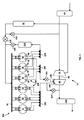
ここに開示する排出ガス再循環技術は、2つ以上の燃焼室を有するエンジンに適用しうるものである。例えば、図1に示す第1の実施例を参照するに、6つの燃焼室11、12、13、14、15及び16を有する内燃機関101が示されている。各燃焼室は、それぞれ一対の吸気弁21、22、23、24、25及び26を有しており、これら吸気弁は、空気を含む混合体を吸気マニホールド50からそれぞれの吸気ポートを介してそれぞれの燃焼室11、12、13、14、15及び16に送給する作用を行うことができる。この図では、吸気ポートを、吸気マニホールド50とそれぞれの燃焼室11、12、13、14、15及び16との間のラインとして表している。空気はエアフィルタ60を介してエンジン101内に送給されるとともにタービン‐コンプレッサ装置75により加圧される。タービン80は燃焼室からの排出ガスにより駆動されてシャフト90によりコンプレッサ70を駆動するようになっている。吸気の温度は圧縮の末に高められる。吸気が絞り弁110を介して吸気マニホールド50に入れられる前に、この吸気の温度を低下させるために吸気クーラ95が採用されている。コンプレッサ再循環弁120は、コンプレッサ70を経てクーラ95から生じる圧縮且つ冷却された空気を再循環させて、絞り弁110を調整する際にこのコンプレッサがサージング/スタリング(失速)するのを保護するようにする。例えば、絞り弁110が突然閉じられた場合に、コンプレッサ70からの空気のスラグが絞り弁110から反射されてこのコンプレッサの出口に戻りこのコンプレッサを損傷させるおそれがある。従って、コンプレッサの入口における圧力がコンプレッサの出口における圧力よりも低いことにより弁120を開放させることにより、空気のスラグがコンプレッサの入口に戻るようにするものであり、このことは好まいことである。
The exhaust gas recirculation technique disclosed herein can be applied to an engine having two or more combustion chambers. For example, referring to the first embodiment shown in FIG. 1, an
燃焼室11、12、13、14、15及び16は、燃焼室11、12及び13を有する第1の部分130と燃焼室14、15及び16を有する第2の部分140とに分割されている。燃焼室11、12及び13の各々は、排出ガスを燃焼室からそれぞれの排出ポートを介して第1の排出マニホールド150に流す排出弁31、32及び33をそれぞれ有している。この第1の実施例の図示の例では、各シリンダは一対の排出ポートを有しているが、他の実施例では、燃焼室11、12及び13がそれぞれ少なくとも1つの排出弁及びポートを有する必要があるだけである。燃焼室14、15及び16は、排出ガスを燃焼室からそれぞれの排出ポートを介して第2の排出マニホールド160に流す排出弁34、35及び36をそれぞれ有している。更に、燃焼室14、15及び16は、排出ガスを燃焼室からそれぞれのEGRポートを介してEGRマニホールド170に流すEGR排出弁44、45及び46をそれぞれ有している。この図1の開示では、排出ポートを、排出弁31、32、33、34、35及び36とこれらのそれぞれの排出マニホールドとの間のラインとして表しており、EGRポートを、弁44、45及び46とマニホールド170との間のラインとして表している。
The
タービン‐コンプレッサ装置75は、この実施例では、分割ターボチャージャとしても知られているツインスクロールターボチャージャである。タービン80は大型のスクロール入口180と小型のスクロール入口190とを有している。他の実施例では、排出マニホールド150及び160の双方が単一のタービン入口に送給するようにしたモノスクロールタービン‐コンプレッサ装置を採用することができる。第1の排出マニホールド150における排出ガスは大型のスクロール入口180に指向され、第2の排出マニホールド160における排出ガスは小型のスクロール入口190に指向される。第2の排出マニホールド160の出口付近の配管における制限部200は、小型のスクロール入口190と相俟ってマニホールド160及びEGRマニホールド170内の背圧を高め、以下に詳述するようにこれらの背圧が吸気マニホールド50内の圧力よりも大きくなるようにする。排出ガスは、タービン80を出た後に触媒210に向けて指向される。排出ガスがタービン80を側路して直接的に触媒210に向かうようにするためには、ウエィストゲート220を開放することができる。
The turbine-
マニホールド170を通って流れる排出ガスはこのマニホールドからEGRクーラ230に指向され、このクーラにおいて排出ガスの温度が低下される。液化天然ガス(LNG)を採用する分野では、このEGRクーラ230がLNGを採用する熱交換器を有し、この熱交換器が排出ガスから熱を除去する熱交換流体を有し、このように除去された熱が気化の助けを受けてLNGの温度を高めるようにしうる。この目的のためにLNGが入手しえない場合には、エンジン冷却液を熱交換流体として採用することができる。排出ガスは、EGRクーラ230後にEGR弁240を介して吸気マニホールド50に指向させる。EGR排出弁44、45及び46は、これらの燃焼室の爆発行程の終了時付近で又は排出行程中に或いはこれらの双方で動作し、EGRマニホールド170内の圧力が吸気マニホールド50内の圧力よりも高くなるようにする。EGRレート(吸気マニホールド50に再循環される排出ガスの割合)は、排出弁34、35及び36とEGR排出弁44、45及び46とがそれぞれ同時に開放された際の、第2の排出マニホールド160とEGRマニホールド170との間の圧力差に依存する。しかし、多くの排出弁及びEGR弁の事象に対する燃焼室内の圧力は、これらの双方の圧力よりも大きくなりEGRマニホールド170に向かう正の圧力ドライブが生じるようになる。すなわち、燃焼室14、15及び16の各々に対する燃焼室の圧力PCCは、弁開放事象の少なくとも一部分中に第2の排出マニホールド160内の圧力P160及びEGRマニホールド170内の圧力P170よりも大きくなる。上述した装置及び技術により、好適実施例において、第2の排出マニホールドが一般にEGRマニホールドのピーク圧力P170よりも低いピーク圧力P160を有するようにする。P160に対してEGRマニホールド170内の圧力を高めるのに、能動的な又は受動的な或いはその双方のバイアス技術を採用しうる。例えば、第2の排出マニホールド160の出口における制限部200によりマニホールド160及びEGRマニホールド170の双方における圧力を高める。制限部200と組合せて用いうる小型のスクロールタービン入口190を制限(縮小)することにより同様な圧力の増大を得ることができる。ツインスクロールターボチャージャを用いるのが有益である。その理由は、規則的な排出パルスの効果が維持され、これにより隣接するシリンダの点火事象からの排出流間の不所望なパルス干渉を低減させてターボチャージャの効率を改善する為である。他の実施例では、排出弁34、35及び36とEGR排出弁44、45及び46とが可変の弁駆動を採用し、双方が弁の昇降、持続時間及びベースタイミングを制御して第2の排出マニホールド160への流れ、従って、EGRマニホールド170に対する圧力を調整するようにしうる。これらの実施例では、制限部200が不必要となる。例えば、ある動作技術では、排出圧力をブローダウンする場合に排出弁34、35及び36を(これらのそれぞれのサイクルにおいて)容易に開放でき、EGR排出弁44、45及び46をその後に排出ガスの温度が低下した後に開放できるようにする。段階的な弁の開放及び閉成を採用し、これにより排出弁34、35及び36をEGR排出弁44、45及び46よりも早期に閉成させて、EGRに対する排出ガスを捕捉するようにしうる。
Exhaust gas flowing through the manifold 170 is directed from this manifold to the EGR cooler 230 where the temperature of the exhaust gas is reduced. In the field of adopting liquefied natural gas (LNG), this EGR cooler 230 has a heat exchanger that employs LNG, and this heat exchanger has a heat exchange fluid that removes heat from the exhaust gas, thus The removed heat may increase the temperature of the LNG with the help of vaporization. If LNG is not available for this purpose, engine coolant can be employed as the heat exchange fluid. The exhaust gas is directed to the
他の実施例では、制限部200に代えて又はこれに加えて、(図1に示す)タービン80後の又は触媒210後の排出路内の流量面積を調整しうる制限部又はより好ましくは弁201の形態の圧力調整器を設け、これによりEGRマニホールド170内の圧力を高めるのに役立つようにすることができる。排出ガス内のエネルギーは、タービンの後方及び触媒の後方で減少され、これにより前記弁201に加わる応力を制限部200に加わる応力に比べて低くする。この手段の結果、第1のマニホールド150内の背圧が高められるが、このことは必ずしも常に望ましいことではない。エンジン101にエンジンブレーキがある場合には、ポンピング損失を高めることによりエンジンブレーキを改善するのに弁201が有利となりうるものである。
In other embodiments, instead of or in addition to the
更なる実施例では、流量面積を調整しうる弁202の形態の圧力調整器を第2の排出マニホールド160と第1の排出マニホールド150との間に採用することができる。制限部200を弁202とともに採用する場合、この弁202は制限部200の上流のマニホールド160の排出出口をマニホールド150の排出出口に接続する。弁202は、マニホールド160及び170内の圧力をマニホールド150に対して可変的に軽減させて、大型のスクロール入口180が多量の流量を収容するようにしうる。
In a further embodiment, a pressure regulator in the form of a
ここで図2を参照するに、この図には本発明の第2の実施例によるエンジン102が示されており、この実施例及び更なる実施例において第1の実施例と同様な部分には第1の実施例と同じ参照符号を付してあり、これらが存在してもその詳細な説明は省略する。EGR回路は、EGRマニホールド170から受けた排出ガスから水素(H2)及び一酸化炭素(CO)を生ぜしめてこれらを点火性及び火炎速度のような燃焼特性を改善するのに用いるようにするために採用したインライン燃料リフォーミング触媒260を有する。燃料注入装置250は、メタンを有する気体燃料混合体のような燃料(他の種類の燃料を採用しうるが)を排出ガス内に導入して、リフォーミング触媒260よりも前でERG混合体を濃縮するようにする。燃焼特性を改善することにより、EGR混合体及びそのレートの変動に対する許容範囲を改善するとともに燃料の品質を変える。リフォーミング触媒260は、排出ガス中の温水蒸気と燃料注入装置250から噴射されたメタン燃料(他の実施例では他の燃料を採用しうる)とを用いて、これらをH2及びCOに変換する。点火性及び火炎速度は、空気/燃料/リフォーミングされていないEGRの混合体に比べて空気/燃料/リフォーミングされたEGRの混合体に対して改善される。圧縮点火の分野では、H2を燃焼室内に導入した場合に、燃料空気の混合体の点火遅延が減少される。
Reference is now made to FIG. 2, which shows an
次に図3を参照するに、この図には、4つの燃焼室11、12、14及び15を有する本発明の第3の実施例によるエンジン103が示されている。この実施例は、図示の通りにシリンダの個数及びマニホールドへの排出ポートの経路において図1の実施例と相違している。4シリンダエンジンに対する代表的な点火順序は1−3−4−2(シリンダ番号は右手側から始まるものである)であり、この点火順序は図3におけるエンジン103の表示では12、14、11及び15の燃焼室点火順序となる。各タービン入口180及び190はそれぞれの排出マニホールドから360度毎に排出ガスのパルスを受ける。図1に戻って参照するに、6シリンダエンジンに対する代表的な点火順序は1−5−3−6−2−4であり、この点火順序は図1におけるエンジン101の表示では16、12、14、11、15及び13の燃焼室点火順序となる。従って、図1の6シリンダの実施例の場合、各タービン入口180及び190はそれぞれの排出マニホールドから240度毎に排出ガスのパルスを受ける。図3は、4シリンダの実施例と6シリンダの実施例との間の上述した相違とは別に、構成配置及び動作技術の上述したこと以外はほぼ同じである。
Reference is now made to FIG. 3, which shows an
次に図4を参照するに、この図には、EGRマニホールド170内の圧力を所望レベルに低減させるために圧力調整器175を有する本発明の第4の実施例によるエンジン104が示されている。圧力調整器175はバタフライ弁やその他の種類の調整器とすることができる。制限部200は背圧を生ぜしめるとともに、EGRマニホールド170内の圧力を増大させる。EGRマニホールド170内の圧力を所望のレベルに降下させるのにより大規模な制御が望ましい場合には、圧力調整器175を採用する。この技術によりEGRレート応答を改善するとともに、EGRレートを制御してその許容範囲を改善し且つ変動を少なくする。
Referring now to FIG. 4, there is shown an
次に図5を参照するに、この図には、排出路内の背圧及びEGRマニホールド170内の圧力を増大させるために圧力調整器165を有する本発明の第5の実施例によるエンジン105が示されている。圧力調整器165は、バタフライ弁やその他の種類の調整器とすることができる。圧力調整器165はEGR弁240と相俟って所望のEGRレートを制御するように作用する。弁165及び240の各々の所望の開放状態はエンジン回転速度及び負荷状態に依存する。エンジン回転速度が遅いと、EGR弁240は代表的に完全に開放状態にするとともに、弁165は部分的に閉成状態にする。エンジン回転速度が速いと、EGR弁240は(エンジン回転速度が遅い場合に比べて)制限されるとともに、弁165は完全に開放される。他の実施例では、EGR弁240を不要として、クーラ230からの冷却されたEGR排出ガスが吸気マニホールド50に直接向かうようにする。これらの実施例では、EGRの流速は圧力調整器165により制御される。EGR弁が無いこれらの実施例は簡単なシステムであるが、EGRレート制御に関して且つエンジンの過渡動作に対する応答時間に関しても不利益が存在するのに対し、弁165及び240の双方を採用する上述した実施例はより一層有効なEGRレート制御を達成する。
Reference is now made to FIG. 5, which shows an
次に図6を参照するに、この図には、本発明の第6の実施例によるエンジン106が示されている。吸気マニホールドは区分51と区分52とに分割されている。各区分はそれぞれ絞り弁111及び112と、EGR弁241及び242とを有している。それぞれの弁を制御することにより、吸気マニホールドの区分51及び52内に流れる排出ガスの量を制御しうる。このことは、例えば、燃料がシリンダの一部分のみに導入される低負荷時にエンジン106がシリンダのカットアウトモードで動作する場合に有利なことである。EGRが低負荷時に採用され且つ燃焼室14、15及び16のみが採用される場合に、EGR弁241が閉成されると、排出ガスはより一層有効にこれらの燃焼室に向かうようになる。エンジン106は圧力調整器175を有するように示してあるが、図6の実施例の変形では、EGRマニホールド170内の圧力を高める前述した受動的及び能動的な技術を採用することができる。
Reference is now made to FIG. 6, which shows an
次に図7、8及び9を参照するに、これらの図には、吸気クーラ95より前で排出ガスを圧縮吸気と混合する本発明の他の実施例によるエンジン107、108及び109が示されている。これらのエンジンからの排出ガスは、天然ガスのような気体燃料で給油する場合にガソリンで給油する場合に比べて高い水蒸気含有量を有するようになる。通常では、凝結を回避するためには、水を蒸気として残存させる状態に維持するのに充分な高温度に排出ガスを保ち、凝結が生じた場合にエンジン部品に対する潜在的な損傷(例えば、このような損傷は酸の浸食及び液滴衝突により生じるおそれがある)を回避するようにする。このことは、排出ガスを冷却しうる程度を制限する。この場合、シリンダに入る吸気の温度は、比較的熱い後置(ポスト)EGRクーラの排出ガス(約100〜150℃)をより冷却した(50℃よりも低い)吸気と混合した場合に上昇した。本実施例において、飽和度の高い排出ガスをコンプレッサ70からの不飽和吸気と混合すると、この混合体の露点は排出ガスのみの露点よりも低くなる。従って、この混合体を、吸気クーラ95を介して伝達すると、凝結度が低くなり、これにより排出ガスをより低い温度まで冷却させうるようになる。全吸気温度が低くなることにより、吸気密度を高め(これにより容積効率を改善し)且つ早期点火及びノッキングの可能性を低減させる。エンジン107及び108は互いに類似しており、吸気絞り弁の位置においてのみ互いに異なっており、エンジン108における絞り弁の位置によれば、エンジン107では吸気のみが絞られるのに対し混合体が絞られる為に過渡応答が改善される。エンジン107によれば、排出ガスが後置絞り弁で吸気と混合される為、すなわち排出ガスが絞り弁による圧力降下を受けない為、エンジン108に比べて低負荷時にEGR濃度が改善される。エンジン109はEGRクーラ230を有しておらず、吸気クーラ95を通る単一段の冷却を行う(このクーラ95は、EGRクーラ230を無くした図7に類似する他の実施例では絞り弁110に対して後置配置することができることに注意すべきである)。熱い排出ガスを単一段の冷却を介して冷却する場合、熱交換器は排出ガスの高温度に対処しうるようにする必要がある。従来の吸気クーラは、高温度に耐えうるステンレス鋼を有する従来のEGRクーラと対比するに、アルミニウ構造を有している。
Reference is now made to FIGS. 7, 8 and 9, which show
上述した実施例の1つの利点は、好適実施例で、目標とするEGRレートを燃焼の安定性に対する有効なレートである約25%の範囲内に容易に達成するようにEGRマニホールドに関連する排出弁の個数を選択しうることである。EGRに対する専用のシリンダを採用した従来のEGRシステムはこのレートを4シリンダエンジンに対し達成しうるが、6シリンダエンジンに対しては達成しえない。例えば、6シリンダエンジンでは、25%に近い利用可能なEGRレートは16.6%(6つのシリンダの内1つのシリンダ)又は33.3%(6つのシリンダの内2つのシリンダ)の何れかである。前述した実施例では、有効なEGRレートは、シリンダの個数によってではなく、排出弁対EGR排出弁の相対合計数によって決定され、従って、利用可能なEGRレートの選択は最も必要とする領域内でより一層絞り込まれる。完全に専用のEGRマニホールドを採用している従来のEGRシステムでは、排出ガスを半数のシリンダから受けることは、排出ガスの50%を再循環しうることを意味している。25%のEGRレートを達成するには、タービンの入口へ向かう又はタービン後に触媒に入る排出ガスを除去する必要がある。 One advantage of the embodiment described above is that in the preferred embodiment, the emissions associated with the EGR manifold to easily achieve the target EGR rate within the range of about 25%, which is an effective rate for combustion stability. The number of valves can be selected. Conventional EGR systems that employ dedicated cylinders for EGR can achieve this rate for a four cylinder engine, but not for a six cylinder engine. For example, on a 6 cylinder engine, the available EGR rate close to 25% is either 16.6% (1 cylinder out of 6 cylinders) or 33.3% (2 out of 6 cylinders). is there. In the embodiment described above, the effective EGR rate is determined not by the number of cylinders, but by the relative total number of exhaust valves versus EGR exhaust valves, and therefore the selection of available EGR rates is within the most needed area. More narrowed down. In a conventional EGR system that employs a fully dedicated EGR manifold, receiving exhaust gas from half of the cylinders means that 50% of the exhaust gas can be recirculated. To achieve an EGR rate of 25%, it is necessary to remove exhaust gases that enter the catalyst at the turbine inlet or after the turbine.
前述した実施例の他の利点は、ターボパルス同調のためにシリンダが分割され、EGRを駆動するための排出背圧を高めるのに1つのスクロール入口が制限されている非対称のツインスクロールのターボチャージャを採用する分野にある。制限スクロール(入口190)における制限は(従来の非対称のターボハウジングに比べて)減少され、ターボチャージャの効率を増大させる。排出弁の事象を段階的にすることにより、排出ガスの排除及びブローダウンに対する更なる利点が得られる。 Another advantage of the above-described embodiment is that the cylinder is split for turbo pulse tuning and an asymmetric twin scroll turbocharger in which one scroll inlet is limited to increase the exhaust back pressure for driving the EGR. Is in the field of adopting. The restriction at the limiting scroll (inlet 190) is reduced (compared to a conventional asymmetric turbo housing), increasing the efficiency of the turbocharger. By grading the events of the exhaust valve, further advantages to exhaust gas elimination and blowdown are obtained.
上述したところでは、本発明の特定の素子、実施例及び適用分野を開示し且つ説明したが、本発明はこれらに限定されるものではない。その理由は、当業者は本発明の範囲から逸脱することなく特に前述した技術に照らして本発明の変形を達成しうる為である。 While specific elements, examples and fields of application of the present invention have been disclosed and described above, the present invention is not limited to these. This is because those skilled in the art can achieve modifications of the present invention without departing from the scope of the present invention, particularly in light of the techniques described above.
Claims (22)
(b)各燃焼室と関連する少なくとも1つの吸気弁と、
(c)前記複数の燃焼室にそれぞれの吸気弁を介して流体連通する少なくとも1つの吸気マニホールドと、
(d)前記第1の部分の燃焼室における各燃焼室に前記第1の排出弁及び前記第2の排出弁を介して流体連通する第1の排出マニホールドと、
(e)前記第2の部分の燃焼室における各燃焼室に前記第3の排出弁を介して流体連通する第2の排出マニホールドと、
(f)排出ガスを受けるために前記第2の部分の燃焼室における各燃焼室に前記第4の排出弁を介して流体連通し、且つ、排出ガスを供給するために前記少なくとも1つの吸気マニホールドに流体連通するEGRマニホールドと
を具える内燃機関用の排出ガス再循環(EGR)システム。 (A) a plurality of combustion chambers divided into a combustion chamber of a first portion and a combustion chamber of a second portion, wherein each combustion chamber in the combustion chamber of the first portion has a first exhaust valve and a first combustion chamber; A plurality of combustion chambers, wherein each combustion chamber in the combustion chamber of the second portion has a third exhaust valve and a fourth exhaust valve;
(B) at least one intake valve associated with each combustion chamber;
(C) at least one intake manifold in fluid communication with the plurality of combustion chambers via respective intake valves;
(D) a first exhaust manifold that is in fluid communication with each combustion chamber in the combustion chamber of the first portion via the first exhaust valve and the second exhaust valve;
(E) a second exhaust manifold in fluid communication with each combustion chamber in the combustion chamber of the second portion via the third exhaust valve;
(F) fluid communication through the fourth exhaust valve to each combustion chamber in the combustion chamber of the second portion for receiving exhaust gas, and the at least one intake manifold for supplying exhaust gas An exhaust gas recirculation (EGR) system for an internal combustion engine comprising an EGR manifold in fluid communication with the engine.
(h)タービン及びコンプレッサを有するタービン‐コンプレッサ装置
を具えており、前記タービンは前記コンプレッサを駆動するものであり、前記タービンは第1の排出入口及び第2の排出入口を有し、前記第2の排出入口は前記第1の排出入口よりも小さい流量面積を有し、前記第1の排出マニホールドは前記第1の排出入口に流体連通しており、前記第2の排出マニホールドは前記第2の排出入口に流体連通しており、前記吸気マニホールドは前記コンプレッサと流体連通して、酸素を有する圧縮気体の混合体を受けるようになっている排出ガス再循環システム。 In exhaust gas recirculation system according to claim 1, the exhaust gas recirculation system further
(h) a turbine-compressor device having a turbine and a compressor, wherein the turbine drives the compressor, the turbine having a first exhaust inlet and a second exhaust inlet, and the second The first discharge manifold has a smaller flow area than the first discharge inlet, the first discharge manifold is in fluid communication with the first discharge inlet, and the second discharge manifold is the second discharge manifold. An exhaust gas recirculation system in fluid communication with an exhaust inlet, wherein the intake manifold is in fluid communication with the compressor to receive a mixture of compressed gases having oxygen.
(i)前記第2の排出マニホールドと前記第1の排出マニホールドとの間に存在し、前記第2の排出マニホールド及び前記EGRマニホールド内の圧力を低減させるように動作しうる圧力調整器
を具えている排出ガス再循環システム。 The exhaust gas recirculation system of claim 2, wherein the exhaust gas recirculation system further comprises:
(i) comprising a pressure regulator present between the second discharge manifold and the first discharge manifold and operable to reduce pressure in the second discharge manifold and the EGR manifold; Exhaust gas recirculation system .
(i)前記タービン後の排出流路内に設けられ、前記第1の排出マニホールドと、前記第2の排出マニホールドと、前記EGRマニホールドの背圧を変化させる圧力調整器を具えている排出ガス再循環システム。 The exhaust gas recirculation system of claim 2, wherein the exhaust gas recirculation system further comprises:
(I) Exhaust gas recirculation provided in the exhaust flow path after the turbine and comprising a pressure regulator for changing a back pressure of the first exhaust manifold, the second exhaust manifold, and the EGR manifold. Circulation system .
(h)EGRクーラ及びEGR弁
を具えており、前記EGRクーラは前記EGRマニホールドを前記EGR弁に連結しており、前記EGR弁は前記吸気マニホールドに流体連通している排出ガス再循環システム。 In exhaust gas recirculation system according to claim 1, the exhaust gas recirculation system further
(H) An exhaust gas recirculation system comprising an EGR cooler and an EGR valve, wherein the EGR cooler connects the EGR manifold to the EGR valve, and the EGR valve is in fluid communication with the intake manifold.
(h)前記第2の排出マニホールドと前記タービンの前記第2の排出入口との間に圧力調整器
を具えている排出ガス再循環システム。 The exhaust gas recirculation system of claim 2, wherein the exhaust gas recirculation system further comprises:
(H) An exhaust gas recirculation system comprising a pressure regulator between the second exhaust manifold and the second exhaust inlet of the turbine.
(h)前記EGRマニホールドと前記第2の排出マニホールドとの間に圧力調整器
を具えている排出ガス再循環システム。 In exhaust gas recirculation system according to claim 1, the exhaust gas recirculation system further
(H) An exhaust gas recirculation system comprising a pressure regulator between the EGR manifold and the second exhaust manifold.
(h)前記EGRマニホールドから排出ガスを受けるためにこのEGRマニホールドに流体連通している入口と、前記吸気マニホールドと流体連通している出口とを有するリフォーミング触媒と、
(i)気体燃料を前記リフォーミング触媒の上流で前記排出ガス内に導入する燃料注入装置と
を具えている排出ガス再循環システム。 In exhaust gas recirculation system according to claim 1, the exhaust gas recirculation system further
(H) a reforming catalyst having an inlet in fluid communication with the EGR manifold for receiving exhaust gas from the EGR manifold, and an outlet in fluid communication with the intake manifold;
(I) An exhaust gas recirculation system comprising a fuel injection device for introducing gaseous fuel into the exhaust gas upstream of the reforming catalyst.
(h)前記第1の排出マニホールド及び前記第2の排出マニホールドから排出ガスを受けるタービン‐コンプレッサ装置と、
(i)前記タービン‐コンプレッサ装置から圧縮空気を受ける吸気クーラと、
(j)前記EGRマニホールドと前記吸気クーラの上流との間の可調整弁であって、前記排出ガスが前記可調整弁を経て伝達されるとともに前記圧縮空気と混合されて混合体を形成し、この混合体を前記吸気クーラにより冷却されるようにした当該可調整弁と
を具える排出ガス再循環システム。 In exhaust gas recirculation system according to claim 1, the exhaust gas recirculation system further
(H) a turbine-compressor device that receives exhaust gases from the first exhaust manifold and the second exhaust manifold;
(I) an intake air cooler that receives compressed air from the turbine-compressor device;
(J) an adjustable valve between the EGR manifold and the upstream of the intake air cooler, wherein the exhaust gas is transmitted through the adjustable valve and mixed with the compressed air to form a mixture; An exhaust gas recirculation system comprising the adjustable valve adapted to cool the mixture by the intake air cooler.
(a)前記内燃機関における燃焼室を第1の部分の燃焼室と第2の部分の燃焼室とに分割するステップであって、前記第1の部分の燃焼室における各燃焼室は第1の排出弁及び第2の排出弁を有し、前記第2の部分の燃焼室における各燃焼室は第3の排出弁及び第4の排出弁を有する、ステップと、
(b)前記第1の部分の燃焼室における各燃焼室から前記第1の排出弁及び前記第2の排出弁を介して第1の排出マニホールドに排出ガスを伝達させるステップと、
(c)前記第2の部分の燃焼室における各燃焼室から、前記第3の排出弁を介して第2の排出マニホールドに排出ガスを伝達させ、前記第4の排出弁を介してEGRマニホールドに排出ガスを伝達させるステップと、
(d)排出ガスを前記EGRマニホールドから少なくとも1つの吸気マニホールドに伝達させるステップと
を具える排出ガス再循環方法。 In the exhaust gas recirculation method in an internal combustion engine, this exhaust gas recirculation method is:
(A) dividing a combustion chamber in the internal combustion engine into a first portion combustion chamber and a second portion combustion chamber, wherein each combustion chamber in the first portion combustion chamber is a first portion; A step of having a discharge valve and a second discharge valve, each combustion chamber in the combustion chamber of the second portion having a third discharge valve and a fourth discharge valve;
(B) transmitting exhaust gas from each combustion chamber in the combustion chamber of the first portion to the first exhaust manifold via the first exhaust valve and the second exhaust valve;
(C) Exhaust gas is transmitted from each combustion chamber in the combustion chamber of the second portion to the second exhaust manifold via the third exhaust valve, and to the EGR manifold via the fourth exhaust valve. Transmitting the exhaust gas;
(D) An exhaust gas recirculation method comprising the step of transmitting exhaust gas from the EGR manifold to at least one intake manifold.
(e)前記第2の排出マニホールドからの排出ガスの流れを制限するステップ
を具えている排出ガス再循環方法。 The exhaust gas recirculation method according to claim 12, wherein the exhaust gas recirculation method further comprises:
(E) An exhaust gas recirculation method comprising the step of restricting the flow of exhaust gas from the second exhaust manifold.
(e)排出ガスを前記第1の排出マニホールドから第1のタービン入口に伝達させるステップと、
(f)排出ガスを前記第2の排出マニホールドから、前記第1のタービン入口よりも小さい流量面積を有する第2のタービン入口に伝達させるステップと、
(g)前記排出ガスにより前記タービンに与えられるエネルギーで酸素を有する気体の混合体を圧縮させるステップと
を具える排出ガス再循環方法。 The exhaust gas recirculation method according to claim 12, wherein the exhaust gas recirculation method further comprises:
(E) transmitting exhaust gas from the first exhaust manifold to a first turbine inlet;
(F) transmitting exhaust gas from the second exhaust manifold to a second turbine inlet having a smaller flow area than the first turbine inlet;
(G) an exhaust gas recirculation method comprising: compressing a gas mixture having oxygen with energy imparted to the turbine by the exhaust gas.
(h)前記第2の排出マニホールドと前記第1の排出マニホールドとの間の圧力を調整するステップであって、前記第2の排出マニホールド内の前記排出ガスの一部を前記第1のタービン入口に向けて指向させるようにするステップ
を具えている排出ガス再循環方法。 15. The exhaust gas recirculation method according to claim 14, wherein the exhaust gas recirculation method further comprises:
(H) adjusting a pressure between the second exhaust manifold and the first exhaust manifold, wherein a part of the exhaust gas in the second exhaust manifold is converted into the first turbine inlet; Exhaust gas recirculation method comprising the step of directing towards
(h)前記第2の排出マニホールドと前記第2のタービン入口との間の圧力を調整するステップ
を具えている排出ガス再循環方法。 15. The exhaust gas recirculation method according to claim 14, wherein the exhaust gas recirculation method further comprises:
(H) An exhaust gas recirculation method comprising adjusting a pressure between the second exhaust manifold and the second turbine inlet.
(i)前記EGRマニホールドと前記少なくとも1つの吸気マニホールドとの間の圧力を調整するステップ
を具えている排出ガス再循環方法。 The exhaust gas recirculation method of claim 16, wherein the exhaust gas recirculation method further comprises:
(I) An exhaust gas recirculation method comprising adjusting a pressure between the EGR manifold and the at least one intake manifold.
(e)前記EGRマニホールドと前記第2の排出マニホールドの出口との間の圧力を調整するステップ
を具えている排出ガス再循環方法。 The exhaust gas recirculation method according to claim 12, wherein the exhaust gas recirculation method further comprises:
(E) An exhaust gas recirculation method comprising the step of adjusting the pressure between the EGR manifold and the outlet of the second exhaust manifold.
(e)前記第3の排出弁及び前記第4の排出弁を可変駆動して前記第2の排出マニホールド内の圧力を制御することにより、EGRレートを調整するステップ
を具えている排出ガス再循環方法。 The exhaust gas recirculation method according to claim 12, wherein the exhaust gas recirculation method further comprises:
(E) Exhaust gas recirculation comprising the step of adjusting the EGR rate by variably driving the third exhaust valve and the fourth exhaust valve to control the pressure in the second exhaust manifold Method.
(e)炭化水素燃料を前記EGRマニホールドからの排出ガス内に導入することにより排出ガス‐燃料混合体を形成するステップと、
(f)前記排出ガス‐燃料混合体をリフォーミングして少なくとも水素を発生させるステップと、
(g)前記水素及び前記排出ガスを前記少なくとも1つの吸気マニホールドに伝達させるステップと
を具えている排出ガス再循環方法。 The exhaust gas recirculation method according to claim 12, wherein the exhaust gas recirculation method further comprises:
(E) forming an exhaust gas-fuel mixture by introducing hydrocarbon fuel into the exhaust gas from the EGR manifold;
(F) reforming the exhaust gas-fuel mixture to generate at least hydrogen;
(G) an exhaust gas recirculation method comprising: transferring the hydrogen and the exhaust gas to the at least one intake manifold.
(e)前記排出ガス‐燃料混合体をリフォーミングして一酸化炭素を生ぜしめるステップ
を具えている排出ガス再循環方法。 The exhaust gas recirculation method according to claim 12, wherein the exhaust gas recirculation method further comprises:
(E) An exhaust gas recirculation method comprising the step of reforming the exhaust gas-fuel mixture to produce carbon monoxide.
(e)タービン‐コンプレッサ装置により吸気を圧縮させて圧縮吸気を形成するステップと、
(f)排出ガスを前記圧縮吸気と混合して混合体を形成するステップと、
(g)前記排出ガスと前記圧縮吸気との前記混合体を前記少なくとも1つの吸気マニホールドに導入する前にこの混合体を冷却するステップと
を具えている排出ガス再循環方法。 The exhaust gas recirculation method according to claim 12, wherein the exhaust gas recirculation method further comprises:
(E) compressing intake air by a turbine-compressor device to form compressed intake air;
(F) mixing exhaust gas with the compressed intake air to form a mixture;
(G) An exhaust gas recirculation method comprising: cooling the mixture of the exhaust gas and the compressed intake air before introducing the mixture into the at least one intake manifold.
Applications Claiming Priority (3)
| Application Number | Priority Date | Filing Date | Title |
|---|---|---|---|
| US201361870203P | 2013-08-26 | 2013-08-26 | |
| US61/870,203 | 2013-08-26 | ||
| PCT/CA2014/050817 WO2015027335A1 (en) | 2013-08-26 | 2014-08-26 | Direct exhaust gas recirculation system |
Publications (2)
| Publication Number | Publication Date |
|---|---|
| JP2016534279A JP2016534279A (en) | 2016-11-04 |
| JP6560675B2 true JP6560675B2 (en) | 2019-08-14 |
Family
ID=52585337
Family Applications (1)
| Application Number | Title | Priority Date | Filing Date |
|---|---|---|---|
| JP2016537060A Active JP6560675B2 (en) | 2013-08-26 | 2014-08-26 | Direct exhaust gas recirculation system |
Country Status (7)
| Country | Link |
|---|---|
| US (1) | US10094339B2 (en) |
| EP (1) | EP3039279B1 (en) |
| JP (1) | JP6560675B2 (en) |
| CN (1) | CN105492752B (en) |
| CA (1) | CA2922577C (en) |
| RU (1) | RU2665010C2 (en) |
| WO (1) | WO2015027335A1 (en) |
Families Citing this family (29)
| Publication number | Priority date | Publication date | Assignee | Title |
|---|---|---|---|---|
| US9249761B2 (en) * | 2013-06-13 | 2016-02-02 | Cummins Inc. | Exhaust gas recirculation and control with twin scroll turbines |
| US10215134B2 (en) * | 2015-07-02 | 2019-02-26 | Cummins Inc. | Engine arrangements with EGR systems |
| JP6562847B2 (en) * | 2016-02-04 | 2019-08-21 | 大阪瓦斯株式会社 | Engine system and control method thereof |
| JP6670151B2 (en) * | 2016-03-30 | 2020-03-18 | 株式会社Subaru | Engine system |
| KR20170139926A (en) * | 2016-06-10 | 2017-12-20 | 현대자동차주식회사 | Engine systme having exahust gas recirculation apparatus and control mehtod using the same |
| US10107220B2 (en) * | 2016-12-16 | 2018-10-23 | Ford Global Technologies, Llc | Systems and methods for a split exhaust engine system |
| US10683817B2 (en) * | 2016-12-16 | 2020-06-16 | Ford Global Technologies, Llc | Systems and methods for a split exhaust engine system |
| US10138822B2 (en) * | 2016-12-16 | 2018-11-27 | Ford Global Technologies, Llc | Systems and methods for a split exhaust engine system |
| CN106762130A (en) * | 2017-03-14 | 2017-05-31 | 观致汽车有限公司 | Engine system and the automobile using the engine system |
| CN106762131B (en) * | 2017-03-14 | 2022-10-14 | 观致汽车有限公司 | Engine system and automobile applying same |
| CN106762129A (en) * | 2017-03-14 | 2017-05-31 | 观致汽车有限公司 | Engine system and the automobile using the engine system |
| CN106870131B (en) * | 2017-03-14 | 2023-01-31 | 观致汽车有限公司 | Engine system and automobile applying same |
| SE540569C2 (en) * | 2017-03-16 | 2018-10-02 | Freevalve Ab | Internal combustion engine and method for controlling such an internal combustion engine |
| CN107061053B (en) * | 2017-06-01 | 2022-11-01 | 武汉理工大学 | Exhaust gas-fuel reforming recycling natural gas engine system and control method |
| US10570822B2 (en) * | 2017-06-26 | 2020-02-25 | Garrett Transportation I Inc. | Exhaust manifold system for turbocharger device with plural volute members |
| US10145320B1 (en) | 2017-08-31 | 2018-12-04 | Ford Global Technologies, Llc | Methods and systems for boost and EGR control |
| TR201717052A1 (en) * | 2017-11-01 | 2019-05-21 | Ford Otomotiv Sanayi As | CROSS EXHAUST MANIFOLD |
| JP6825541B2 (en) * | 2017-11-15 | 2021-02-03 | トヨタ自動車株式会社 | EGR controller |
| EP3499016B1 (en) * | 2017-12-14 | 2024-07-03 | MoldTecs-01-2022 GmbH | Air duct arrangement and internal combustion engine |
| US11261804B2 (en) | 2018-02-16 | 2022-03-01 | Volvo Truck Corporation | Internal combustion engine system |
| JP7163251B2 (en) * | 2019-07-11 | 2022-10-31 | 愛三工業株式会社 | EGR gas distributor |
| CN110230556A (en) * | 2019-08-02 | 2019-09-13 | 潍柴动力股份有限公司 | A kind of egr system and a kind of engine |
| CN110529301A (en) * | 2019-08-29 | 2019-12-03 | 武汉理工大学 | Downflow type LNG engine exhaust reformer |
| AT523712B1 (en) * | 2020-05-14 | 2021-11-15 | Avl List Gmbh | COMBUSTION ENGINE |
| CH717411A1 (en) * | 2020-05-14 | 2021-11-15 | Liebherr Machines Bulle Sa | Supercharged internal combustion engine with optimized exhaust gas recirculation. |
| EP3922826A1 (en) * | 2020-06-12 | 2021-12-15 | Volvo Truck Corporation | A control unit and method therein for controlling exhaust valves of cylinders in an internal combustion engine |
| JP7435381B2 (en) | 2020-09-23 | 2024-02-21 | マツダ株式会社 | engine system |
| CN112610368B (en) * | 2020-12-10 | 2022-07-12 | 一汽解放汽车有限公司 | Exhaust assembly and vehicle |
| CN115163352B (en) * | 2022-06-24 | 2024-04-09 | 武汉理工大学 | Waste heat utilization system and engine based on exhaust gas reforming recirculation |
Family Cites Families (28)
| Publication number | Priority date | Publication date | Assignee | Title |
|---|---|---|---|---|
| US4179892A (en) * | 1977-12-27 | 1979-12-25 | Cummins Engine Company, Inc. | Internal combustion engine with exhaust gas recirculation |
| JPS63150068U (en) * | 1987-03-21 | 1988-10-03 | ||
| US6003315A (en) * | 1997-03-31 | 1999-12-21 | Caterpillar Inc. | Exhaust gas recirculation system for an internal combustion engine |
| SE9801544L (en) | 1998-05-04 | 1999-04-26 | Scania Cv Ab | Device for exhaust gas return on combustion engine and an engine comprising such a device |
| US6220233B1 (en) * | 1999-10-13 | 2001-04-24 | Caterpillar Inc. | Exhaust gas recirculation system having variable valve timing and method of using same in an internal combustion engine |
| DE19963358A1 (en) * | 1999-12-28 | 2001-07-12 | Bosch Gmbh Robert | Method and device for controlling an internal combustion engine with an air system |
| CA2342404C (en) * | 2000-03-27 | 2007-05-15 | Mack Trucks, Inc. | Turbocharged engine with exhaust gas recirculation |
| US6347619B1 (en) * | 2000-03-29 | 2002-02-19 | Deere & Company | Exhaust gas recirculation system for a turbocharged engine |
| US6508209B1 (en) * | 2000-04-03 | 2003-01-21 | R. Kirk Collier, Jr. | Reformed natural gas for powering an internal combustion engine |
| JP2002089377A (en) | 2000-09-11 | 2002-03-27 | Mitsubishi Motors Corp | EGR device |
| SE519321C2 (en) * | 2001-06-29 | 2003-02-11 | Saab Automobile | Ways to operate an internal combustion engine and internal combustion engine |
| JP4168809B2 (en) * | 2003-04-03 | 2008-10-22 | いすゞ自動車株式会社 | Exhaust turbocharged engine with EGR |
| SE531208C8 (en) * | 2004-03-31 | 2009-02-17 | ||
| US7269950B2 (en) * | 2004-05-05 | 2007-09-18 | Precision Industries, Inc. | Staged turbocharger |
| US7377270B2 (en) * | 2006-10-23 | 2008-05-27 | Caterpillar Inc. | Exhaust gas recirculation in a homogeneous charge compression ignition engine |
| US20080295501A1 (en) * | 2007-05-31 | 2008-12-04 | Weidong Gong | Stoichiometric engine system utilizing reformed exhaust gas |
| US8176737B2 (en) * | 2008-07-31 | 2012-05-15 | Caterpillar Inc. | Exhaust system having 3-way valve |
| US8161747B2 (en) * | 2008-07-31 | 2012-04-24 | Caterpillar Inc. | Exhaust system having series turbochargers and EGR |
| US8196403B2 (en) * | 2008-07-31 | 2012-06-12 | Caterpillar Inc. | Turbocharger having balance valve, wastegate, and common actuator |
| DE102008039085A1 (en) * | 2008-08-21 | 2010-02-25 | Daimler Ag | Internal combustion engine with an exhaust gas turbocharger |
| US8640457B2 (en) * | 2009-10-13 | 2014-02-04 | General Electric Company | System and method for operating a turbocharged engine |
| CN102667083B (en) * | 2009-12-08 | 2015-03-25 | 丰田自动车株式会社 | Exhaust gas purification system for an internal combustion engine |
| US20110289914A1 (en) * | 2010-05-28 | 2011-12-01 | Caterpillar Inc. | Upstream egr restriction |
| US8528530B2 (en) * | 2010-06-30 | 2013-09-10 | General Electric Company | Diesel engine system and control method for a diesel engine system |
| DE102011002553A1 (en) * | 2011-01-12 | 2012-07-12 | Ford Global Technologies, Llc | Charged internal combustion engine and method for operating such an internal combustion engine |
| WO2013080600A1 (en) * | 2011-12-01 | 2013-06-06 | トヨタ自動車株式会社 | Internal combustion engine with supercharger |
| JP5922402B2 (en) * | 2011-12-28 | 2016-05-24 | 三菱重工業株式会社 | Twin scroll turbocharger |
| US9453465B2 (en) * | 2013-05-07 | 2016-09-27 | Ford Global Technologies, Llc | Direct injection of diluents or secondary fuels in gaseous fuel engines |
-
2014
- 2014-08-26 WO PCT/CA2014/050817 patent/WO2015027335A1/en active Application Filing
- 2014-08-26 CN CN201480047188.3A patent/CN105492752B/en active Active
- 2014-08-26 JP JP2016537060A patent/JP6560675B2/en active Active
- 2014-08-26 US US14/914,902 patent/US10094339B2/en active Active
- 2014-08-26 RU RU2016107925A patent/RU2665010C2/en active
- 2014-08-26 EP EP14840876.8A patent/EP3039279B1/en active Active
- 2014-08-26 CA CA2922577A patent/CA2922577C/en active Active
Also Published As
| Publication number | Publication date |
|---|---|
| RU2016107925A (en) | 2017-10-03 |
| JP2016534279A (en) | 2016-11-04 |
| CN105492752A (en) | 2016-04-13 |
| RU2665010C2 (en) | 2018-08-24 |
| CA2922577C (en) | 2023-03-14 |
| EP3039279A4 (en) | 2017-03-01 |
| CA2922577A1 (en) | 2015-03-05 |
| CN105492752B (en) | 2019-09-24 |
| EP3039279A1 (en) | 2016-07-06 |
| US10094339B2 (en) | 2018-10-09 |
| RU2016107925A3 (en) | 2018-06-22 |
| WO2015027335A1 (en) | 2015-03-05 |
| EP3039279B1 (en) | 2020-04-08 |
| US20160215736A1 (en) | 2016-07-28 |
Similar Documents
| Publication | Publication Date | Title |
|---|---|---|
| JP6560675B2 (en) | Direct exhaust gas recirculation system | |
| JP6907157B2 (en) | Internal combustion engine that is internally cooled and its method | |
| US9650949B2 (en) | EGR rate control for internal combustion engine with dual exhaust-ported cylinders | |
| US11015553B2 (en) | Exhaust gas recirculation and control with twin scroll turbines | |
| US9175644B2 (en) | Engine with exhaust gas recirculation system and variable geometry turbocharger | |
| US9359976B2 (en) | Engine with pulse-suppressed dedicated exhaust gas recirculation | |
| US8020539B2 (en) | Device for distributing incoming gases in an internal combustion air supply system | |
| US9309804B2 (en) | Dual path (low pressure loop and high pressure loop) EGR for improved air boosting efficiency | |
| WO2007027327A2 (en) | Increasing hydrogen content in egr system | |
| US8640456B2 (en) | Charge air cooler assembly | |
| US20180163612A1 (en) | Method for operating an internal combustion engine | |
| US8146572B2 (en) | Cooled exhaust gas recirculation system with cylinder-level control | |
| WO2020122107A1 (en) | Internal combustion engine system, vehicle, and fuel supply method | |
| US20160010602A1 (en) | Intake Manifold Overpressure Compensation For Internal Combustion Engines | |
| US8408189B2 (en) | Petrol engine having a low-pressure EGR circuit | |
| KR101646123B1 (en) | Engine system with intake gas individually cooled per cylinder | |
| JP2019143616A (en) | Internal combustion engine | |
| KR20250088772A (en) | Gas Engine System |
Legal Events
| Date | Code | Title | Description |
|---|---|---|---|
| RD01 | Notification of change of attorney |
Free format text: JAPANESE INTERMEDIATE CODE: A7426 Effective date: 20161221 |
|
| A521 | Request for written amendment filed |
Free format text: JAPANESE INTERMEDIATE CODE: A821 Effective date: 20161221 |
|
| A621 | Written request for application examination |
Free format text: JAPANESE INTERMEDIATE CODE: A621 Effective date: 20170815 |
|
| A131 | Notification of reasons for refusal |
Free format text: JAPANESE INTERMEDIATE CODE: A131 Effective date: 20180522 |
|
| A977 | Report on retrieval |
Free format text: JAPANESE INTERMEDIATE CODE: A971007 Effective date: 20180524 |
|
| A131 | Notification of reasons for refusal |
Free format text: JAPANESE INTERMEDIATE CODE: A131 Effective date: 20190108 |
|
| A521 | Request for written amendment filed |
Free format text: JAPANESE INTERMEDIATE CODE: A523 Effective date: 20190121 |
|
| A131 | Notification of reasons for refusal |
Free format text: JAPANESE INTERMEDIATE CODE: A131 Effective date: 20190205 |
|
| A521 | Request for written amendment filed |
Free format text: JAPANESE INTERMEDIATE CODE: A523 Effective date: 20190424 |
|
| TRDD | Decision of grant or rejection written | ||
| A01 | Written decision to grant a patent or to grant a registration (utility model) |
Free format text: JAPANESE INTERMEDIATE CODE: A01 Effective date: 20190625 |
|
| A61 | First payment of annual fees (during grant procedure) |
Free format text: JAPANESE INTERMEDIATE CODE: A61 Effective date: 20190719 |
|
| R150 | Certificate of patent or registration of utility model |
Ref document number: 6560675 Country of ref document: JP Free format text: JAPANESE INTERMEDIATE CODE: R150 |
|
| R250 | Receipt of annual fees |
Free format text: JAPANESE INTERMEDIATE CODE: R250 |
|
| R250 | Receipt of annual fees |
Free format text: JAPANESE INTERMEDIATE CODE: R250 |
|
| R250 | Receipt of annual fees |
Free format text: JAPANESE INTERMEDIATE CODE: R250 |