JP6557635B2 - Cooker - Google Patents
Cooker Download PDFInfo
- Publication number
- JP6557635B2 JP6557635B2 JP2016097582A JP2016097582A JP6557635B2 JP 6557635 B2 JP6557635 B2 JP 6557635B2 JP 2016097582 A JP2016097582 A JP 2016097582A JP 2016097582 A JP2016097582 A JP 2016097582A JP 6557635 B2 JP6557635 B2 JP 6557635B2
- Authority
- JP
- Japan
- Prior art keywords
- cover
- heating cooker
- main body
- opening
- cooker
- Prior art date
- Legal status (The legal status is an assumption and is not a legal conclusion. Google has not performed a legal analysis and makes no representation as to the accuracy of the status listed.)
- Active
Links
Images


Description
本発明は、流し台に組み込んで使用する組込式の加熱調理器に関するものである。 The present invention relates to a built-in heating cooker used by being incorporated in a sink.
流し台に組み込んで使用する組込式の加熱調理器として、特許文献1、または特許文献2に記載のものがある。この加熱調理器は、調理器本体を流し台の上面開口部から挿入し、流し台の前面開口部に調理器本体の前部を臨ませるように設置するものである。
As a built-in heating cooker used by being incorporated in a sink, there are those described in Patent Document 1 or
一般に、上面開口部の幅Aより前面開口部の幅Bが広いため(例えばA=560mm、B=600mm)、前面開口部の左右には隙間(約20mm)が生じる。そこで、特許文献1では、調理器本体の左右に生じる隙間にサイドカバーを差し込んで左右隙間を覆い隠している。また、特許文献2では、前面開口部に臨ませる調理器本体が本体幅より狭くなっているため、前面開口部の左右には、更に大きな隙間が生じ、より大きなサイドカバーが必要になっている。
Generally, since the width B of the front opening is wider than the width A of the upper opening (for example, A = 560 mm, B = 600 mm), a gap (about 20 mm) is formed on the left and right of the front opening. So, in patent document 1, the side cover is inserted in the clearance gap which arises in the right and left of a cooking appliance main body, and the left-right clearance gap is covered and concealed. Moreover, in
特許文献1では、サイドカバーを取り付ける際に、調理器本体の側面に設けられた凹部または穴部に、サイドカバーの裏面に設けられた凸部を嵌め込むか差し込んで取り付けるが、サイドカバーが左右に分割されているため、左右の隙間を均等に合わせる必要があり、サイドカバーの取り付けに時間を要してしまうという問題があった。 In Patent Document 1, when attaching the side cover, the convex part provided on the back surface of the side cover is fitted or inserted into the concave part or hole provided on the side surface of the cooker body. Therefore, there is a problem in that it takes time to attach the side cover.
特許文献2では、左右のサイドカバーが上端で細い部分で繋がった構成で、広い流し台との隙間をサイドカバーで覆っているが、調理中などに誤ってサイドカバーに接触したときなどに、ねじれやそりなどの強度に不安がある。また、調理器本体の前面と左右のサイドカバーが分割されると、流し台に組み込んだ際のスッキリ感や一体感がなく、意匠性に難がある。
In
上記の問題を解決するために、本発明は、流し台の上面開口部から挿入し、該流し台の前面開口部に加熱調理器の前部を臨ませ、前記前面開口部と前記加熱調理器の前部の隙間を覆うカバーを装着した加熱調理器であって、前記カバーは、前記加熱調理器の前部の上部を覆う上カバーと、前記加熱調理器の前部の下部を覆う下カバーと、前記加熱調理器の前部の側方の隙間を覆うサイドカバーとが一体化されており、前記一体化されたカバーは、少なくとも一部に樹脂系の表面コーティングがされており、前記上カバーと前記下カバーと前記サイドカバーとで囲われたカバー開口領域の広さは、前記加熱調理器の前部と略同じ広さであることに特徴がある。
In order to solve the above problems, the present invention is inserted from the upper surface opening of the sink, the front portion of the heating cooker faces the front opening of the sink, and the front opening and the front of the heating cooker. A heating cooker equipped with a cover that covers the gap between the upper part, the cover is an upper cover that covers the upper part of the front part of the heating cooker, and a lower cover that covers the lower part of the front part of the heating cooker, A side cover that covers the gap on the side of the front of the heating cooker is integrated, and the integrated cover is at least partially coated with a resin-based surface, and the upper cover The area of the cover opening area enclosed by the lower cover and the side cover is substantially the same as the front part of the cooking device .
本発明によれば、カバーの取付けの際の位置決めが不要で、前面開口部の隙間にカバーを容易に取付けられ、短時間に設置できるとともに、前面カバー全体の強度を有することができる。 According to the present invention, positioning at the time of attachment of the cover is unnecessary, the cover can be easily attached to the gap of the front opening, can be installed in a short time, and can have the strength of the entire front cover.
以下、本発明の実施例を、キッチンに嵌め込むビルトイン型加熱調理器を例に、上記図面に従って説明する。 Hereinafter, an embodiment of the present invention will be described with reference to the above drawings, taking a built-in cooking device fitted in a kitchen as an example.
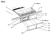
図1から図3において、加熱調理器の本体2は、流し台であるシステムキッチン1の上面から落とし込んで設置することで組み込まれる。本体2をシステムキッチン1の上面開口部から挿入しシステムキッチン1の前面に設けた前面開口部1bに本体前面2bを臨ませて設置する。
1 to 3, the
調理を行う被加熱物の鍋(図示せず)は、本体2の上面に配置された耐熱ガラス等からなり光を透過するプレート3の載置部6に載置されることで調理可能となる。
A pan (not shown) of an object to be cooked for cooking can be cooked by being placed on the placing portion 6 of the plate 3 made of heat-resistant glass or the like disposed on the upper surface of the
載置部6は、本体2上面のプレート3の上面手前に載置部右6aと載置部左6bが配置され、これら両載置部6aおよび6bの間の奥(中央後部)に載置部中央6cが配置されている。そして、プレート3を挟んで各載置部6の下に鍋を加熱するための後述する加熱コイルユニット25がそれぞれ設置されている。配置は、載置部右6aの下方には加熱コイルユニット右25aが、載置部左6bの下方には加熱コイルユニット左25bが、載置部中央6cの下方には加熱ヒーター中央26が設けられている。
The placement unit 6 has a
プレート3の周囲端面には、プレート3を保護するためにフレーム14が設けられている。
A
本体2の内部には、加熱手段である後述する加熱コイルユニット25や制御回路を構成する電子部品が設けられており、該加熱コイルユニット25や制御回路の後方には、これらを冷却するための送風ファン20と、本体2の外部から空気を吸込むための吸気口7及び冷却後の排気を排出する排気口8が設けられている。
Inside the
前記吸気口7で吸入した空気は、本体2の内部で発熱する後述する加熱コイルユニット25や電子部品を冷却した後に排気口8から本体2外に排出される。
Air sucked through the air inlet 7 is discharged from the
また、本体2の本体前面2bの左側には、魚やピザなどを焼くためのロースター4が設けられている。
A roaster 4 for baking fish, pizza and the like is provided on the left side of the main
また、本体2の本体前面2bの右側には、吸気口に繋がる空間としているが、前面パネルの内部に収納する操作部を設けたものでも良い。
In addition, a space connected to the intake port is provided on the right side of the main
次に、図2において被加熱物の鍋を加熱する加熱手段である加熱コイルについて説明する。 Next, the heating coil which is a heating means for heating the pot of the object to be heated in FIG. 2 will be described.
鍋(図示せず)を加熱するための加熱コイルユニット25は、加熱コイル13とコイルベース24とフェライト(図示せず)から構成され、加熱コイル13の略中央部の空間には、自動調理時など鍋の温度を検知する温度検知素子21や、鍋から放射される赤外線を検知して鍋の温度を検知する赤外線センサー22が取付けられている。
A heating coil unit 25 for heating a pan (not shown) is composed of a
次に、図3において加熱コイル13とインバータ基板の冷却について説明する。
Next, cooling of the
インバータ基板は、左右の加熱コイル13a、13bを駆動するインバータ回路を搭載した左インバータ基板18と右インバータ基板19とで構成されている。
The inverter board includes a
該左インバータ基板18、右インバータ基板19、は基板ケース26上に配置され、電子部品で発熱した熱を効率よく送風ファン20からの冷却風と熱交換して温度を下げるように放熱フィン23が設けられている。
The
図1において、本体2は、加熱の設定などを操作する上面操作部9と、上面操作部9の奥側に加熱の設定などを表示する上面表示部10を備える。
In FIG. 1, the
上面操作部9はプレート3の前面側に設けられ、載置部右6a、載置部中央6c、載置部左6bに対応して右から、上面操作部右9a、上面操作部中央9c、上面操作部左9bが配置されている。そして各上面操作部9の上側には上面表示部右10a、上面表示部中央10c、上面表示部左10bからなる上面表示部10が設けられている。
The upper
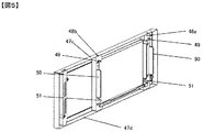
図4から図6において、前面カバー47について説明する。
The
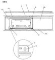
図4は、前面カバーを組み込み前状態の斜視図で、図5は、前面カバーの取付け面側の斜視図、図6は、前面カバー取付け後の正面図である。 4 is a perspective view of a state before the front cover is assembled, FIG. 5 is a perspective view of the mounting surface side of the front cover, and FIG. 6 is a front view after the front cover is mounted.
図4において、本体2の本体前面2bは、システムキッチン1の前面開口部1bとの間で隙間が発生する。これは、一般に、上面開口部の幅Aより前面開口部の幅Bが広いため(例えばA=560mm、B=600mm)、前面開口部の左右には隙間(約20mm)が生じる。また、前面開口部に臨ませる調理器本体が本体幅より狭くなっている場合では、前面開口部の左右には、更に大きな隙間が生じ、より大きなサイドカバーが必要になっている。この隙間に、使用者などが手を入れないよう前面カバー47を前面開口部1bの本体前面2bに取り付けるものである。
In FIG. 4, a gap is generated between the
前面カバー47は、左右の隙間を埋める左サイドカバー47a、右サイドカバー47b、上カバー47c、下カバー47dの4者を一体化で構成される中央が開放された略ロ字状のものであり、四者を別個に形成したものを接続して形成しても良い。
The
次に、図5を用いて前面カバー47を説明する。
Next, the
前面カバーの略ロ字状の開口部47eの裏面には、前面カバー47を本体の前面2bに取り付けるための左サイドピース48aと、右サイドピース48bが備えている。この左右のサイドピース48a、48bの上部には、本体前面2bの上部に設けた角穴2cに嵌合するツメ49が設けられている。また、左右サイドピース48a、48bと、本体前面2bの横幅に対応した凸部50を設け、前面カバーの略ロ字状の開口部47eの内側には、前面カバーを本体前面2bに取付け後、本体前面2bにねじ止め出来るよう固定部51を設けている。
A
図6は、カバー47を正面から見た正面図である。ここに示すように、本実施例の前面カバー47は、左サイドカバー47aと、右サイドカバー47bを、上カバー47cと、下カバー47dとで一体化した構成としている。一体化する方法としては、樹脂系の表面コーテイングを施した化粧鋼板などを用いて、4面を箱状に折り曲げることで、部品数の削減を行なうことも可能である。また、前面カバー47の表面を凹形状に成形することで、一体感とスッキリ感を演出することができる。また、一体化された前面カバー47とすることでねじれなどの変形を抑制している。
FIG. 6 is a front view of the
また、前記固定部51に設ける取付け穴を長穴52形状にすることで、システムキッチン1に本体2を組み込み、前面カバー47を取り付けたあとで、前面開口部1bと、前面カバー47の隙間(約3〜5mm)をねじ取付け時の締付調整により調整することも可能とし、取付け後に前面カバー47に接触して外れることも防止している。
In addition, by making the mounting hole provided in the fixing
本実施例は以上の構成よりなるもので、次にその動作について説明する。 The present embodiment has the above configuration, and the operation thereof will be described next.
本体2をシステムキッチン1に組込み、前面開口部1bの隙間に前面カバー47を取りつけ、本体2の本体前面2bを、前面カバーの略ロ字状の開口部に左右位置を調整する。その後、本体前面2bに、前面カバー47の略ロ字状の左右に設けた左右サイドピースのツメを本体前面2上面の角穴2cに嵌合させ、略ロ字状の開口部に設けた固定部51をねじ取付けにて、仮固定し、前面開口部1bと、前面カバー47の隙間(約3〜5mm)を均等化する位置で、ねじ締付を行ない、固定する。
The
以上説明したように、本発明によれば、カバーの取付けの際の位置決めが不要で、前面開口部の隙間にカバーを容易に取付けられ、短時間に設置できるとともに、前面カバー全体の強度を有するものである。 As described above, according to the present invention, positioning at the time of mounting the cover is unnecessary, the cover can be easily mounted in the gap of the front opening, can be installed in a short time, and has the strength of the entire front cover. Is.
1 システムキッチン
1a 上面開口部、 1b 前面開口部
2 本体
2a 側面、2b 本体前面、 2c 角穴
3 プレート
4 ロースター
7 吸気口
8 排気口
9 上面操作部
10 上面表示部
13 加熱コイル
14 フレーム
18 左インバータ基板
19 右インバータ基板
20 送風ファン
21 温度検知素子
22 赤外線センサー
23 放熱フィン
24 コイルベース
25 加熱コイルユニット
26 加熱ヒーター
47 前面カバー
47a 左サイドカバー、 47b 右サイドカバー
47c 上カバー、 47d 下カバー
48a 左サイドピース、 48b 右サイドピース
49 ツメ
50 凸部
51 固定部
52 長穴
DESCRIPTION OF SYMBOLS 1
Claims (4)
前記カバーは、前記加熱調理器の前部の上部を覆う上カバーと、
前記加熱調理器の前部の下部を覆う下カバーと、
前記加熱調理器の前部の側方の隙間を覆うサイドカバーとが一体化されており、
前記一体化されたカバーは、
少なくとも一部に樹脂系の表面コーティングがされており、
前記上カバーと前記下カバーと前記サイドカバーとで囲われたカバー開口領域の広さは、前記加熱調理器の前部と略同じ広さであることを特徴とする加熱調理器。 A heating cooker that is inserted from the upper surface opening of the sink, has the front part of the cooking appliance facing the front opening of the sink, and is equipped with a cover that covers the gap between the front opening and the front part of the heating cooker. There,
The cover is an upper cover that covers an upper part of a front portion of the cooking device;
A lower cover covering the lower part of the front of the heating cooker;
The side cover that covers the gap on the side of the front of the heating cooker is integrated ,
The integrated cover is
At least a part of the resin surface coating is applied,
Width of the upper cover and the lower cover the cover opening region surrounded by the side cover, the cooking device to the front and substantially characterized as wide der Rukoto of the heating cooker.
前記一体化されたカバーは、前記加熱調理器と接続するためのねじが挿入される取付け穴を有する固定部を前記カバー開口領域に備えることを特徴とする加熱調理器。 The heating cooker according to claim 1, wherein
The integrated cooker is provided with a fixing portion having a mounting hole into which a screw for connecting to the cooker is inserted in the cover opening region .
前記一体化されたカバーは、前記加熱調理器の前部の上端にツメで引掛ける構成とし、前記加熱調理器と接続するためのねじが挿入される取付け穴を有する固定部を前記カバー開口領域に備え、 The integrated cover is configured to be hooked to the upper end of the front portion of the cooking device, and a fixing portion having a mounting hole into which a screw for connecting to the cooking device is inserted is provided in the cover opening region. In preparation for
前記固定部は前記カバー開口領域の下側に設けられており、前記取付け穴を長穴としたことを特徴とする加熱調理器。 The heating cooker, wherein the fixing portion is provided below the cover opening region, and the attachment hole is a long hole.
前記一体化されたカバーは2つの凸部を有し、前記2つの凸部の間の距離は前記加熱調理器の前部の横幅に対応していることを特徴とする加熱調理器。 The integrated cover has two convex portions, and the distance between the two convex portions corresponds to the width of the front portion of the cooking device.
Priority Applications (1)
| Application Number | Priority Date | Filing Date | Title |
|---|---|---|---|
| JP2016097582A JP6557635B2 (en) | 2016-05-16 | 2016-05-16 | Cooker |
Applications Claiming Priority (1)
| Application Number | Priority Date | Filing Date | Title |
|---|---|---|---|
| JP2016097582A JP6557635B2 (en) | 2016-05-16 | 2016-05-16 | Cooker |
Publications (2)
| Publication Number | Publication Date |
|---|---|
| JP2017207216A JP2017207216A (en) | 2017-11-24 |
| JP6557635B2 true JP6557635B2 (en) | 2019-08-07 |
Family
ID=60417013
Family Applications (1)
| Application Number | Title | Priority Date | Filing Date |
|---|---|---|---|
| JP2016097582A Active JP6557635B2 (en) | 2016-05-16 | 2016-05-16 | Cooker |
Country Status (1)
| Country | Link |
|---|---|
| JP (1) | JP6557635B2 (en) |
Family Cites Families (5)
| Publication number | Priority date | Publication date | Assignee | Title |
|---|---|---|---|---|
| JPS5915338U (en) * | 1982-07-21 | 1984-01-30 | 松下電器産業株式会社 | kitchen equipment |
| JPS6252321A (en) * | 1985-09-02 | 1987-03-07 | Matsushita Electric Ind Co Ltd | Cooking device |
| JP2003142246A (en) * | 2001-10-31 | 2003-05-16 | Sanyo Electric Co Ltd | Heating cooker |
| JP2005346967A (en) * | 2004-05-31 | 2005-12-15 | Sharp Corp | Induction heating cooking device |
| JP4448062B2 (en) * | 2005-06-13 | 2010-04-07 | リンナイ株式会社 | Drop-in stove with grill |
-
2016
- 2016-05-16 JP JP2016097582A patent/JP6557635B2/en active Active
Also Published As
| Publication number | Publication date |
|---|---|
| JP2017207216A (en) | 2017-11-24 |
Similar Documents
| Publication | Publication Date | Title |
|---|---|---|
| US8692169B2 (en) | Electrical apparatus having active heat-dissipating element and air circulating system having such electrical apparatus | |
| JP2847364B2 (en) | Gas cookware | |
| JP4820709B2 (en) | Cooker | |
| JP5372855B2 (en) | Cooker | |
| JP6557635B2 (en) | Cooker | |
| JP2008267638A (en) | Heating cooker | |
| CN212438311U (en) | Cooking device | |
| JP5919228B2 (en) | Cooker | |
| KR101620100B1 (en) | A Aooker | |
| JP4869025B2 (en) | Cooker | |
| CN210989801U (en) | Back plate component structure and electric heating kitchen ware | |
| JP4973387B2 (en) | Induction heating cooker | |
| JP6893196B2 (en) | Induction heating cooker | |
| JP6576877B2 (en) | Cooker | |
| CN206775903U (en) | Circuit board radiating device and cooking apparatus | |
| JP2009152101A (en) | Built-in ih cooker | |
| TWI230596B (en) | Heating cooker | |
| KR100771629B1 (en) | Electric range | |
| JP2015138631A (en) | induction heating cooker | |
| JP6410665B2 (en) | Cooker | |
| JP2014137146A (en) | Heating cooker | |
| JP7142319B2 (en) | induction cooker | |
| JP2002280155A (en) | Cooking apparatus | |
| US9677773B2 (en) | Broil baffle for an oven | |
| EP2102559B1 (en) | Built-in cooking appliance |
Legal Events
| Date | Code | Title | Description |
|---|---|---|---|
| A621 | Written request for application examination |
Free format text: JAPANESE INTERMEDIATE CODE: A621 Effective date: 20180214 |
|
| A521 | Written amendment |
Free format text: JAPANESE INTERMEDIATE CODE: A523 Effective date: 20180215 |
|
| A131 | Notification of reasons for refusal |
Free format text: JAPANESE INTERMEDIATE CODE: A131 Effective date: 20181127 |
|
| A521 | Written amendment |
Free format text: JAPANESE INTERMEDIATE CODE: A523 Effective date: 20190125 |
|
| A521 | Written amendment |
Free format text: JAPANESE INTERMEDIATE CODE: A523 Effective date: 20190128 |
|
| TRDD | Decision of grant or rejection written | ||
| A01 | Written decision to grant a patent or to grant a registration (utility model) |
Free format text: JAPANESE INTERMEDIATE CODE: A01 Effective date: 20190618 |
|
| A61 | First payment of annual fees (during grant procedure) |
Free format text: JAPANESE INTERMEDIATE CODE: A61 Effective date: 20190712 |
|
| R150 | Certificate of patent or registration of utility model |
Ref document number: 6557635 Country of ref document: JP Free format text: JAPANESE INTERMEDIATE CODE: R150 |