JP6557351B2 - Earpiece - Google Patents
Earpiece Download PDFInfo
- Publication number
- JP6557351B2 JP6557351B2 JP2017547139A JP2017547139A JP6557351B2 JP 6557351 B2 JP6557351 B2 JP 6557351B2 JP 2017547139 A JP2017547139 A JP 2017547139A JP 2017547139 A JP2017547139 A JP 2017547139A JP 6557351 B2 JP6557351 B2 JP 6557351B2
- Authority
- JP
- Japan
- Prior art keywords
- acoustic
- nozzle
- impedance
- earpiece
- acoustic impedance
- Prior art date
- Legal status (The legal status is an assumption and is not a legal conclusion. Google has not performed a legal analysis and makes no representation as to the accuracy of the status listed.)
- Expired - Fee Related
Links
- 210000000613 ear canal Anatomy 0.000 claims description 58
- 238000007789 sealing Methods 0.000 claims description 38
- 239000012814 acoustic material Substances 0.000 claims description 14
- 239000000463 material Substances 0.000 claims description 10
- 238000010586 diagram Methods 0.000 description 4
- 230000007704 transition Effects 0.000 description 3
- 239000004433 Thermoplastic polyurethane Substances 0.000 description 2
- 238000004891 communication Methods 0.000 description 2
- 230000008878 coupling Effects 0.000 description 2
- 238000010168 coupling process Methods 0.000 description 2
- 238000005859 coupling reaction Methods 0.000 description 2
- 238000000034 method Methods 0.000 description 2
- 230000004044 response Effects 0.000 description 2
- 229920002725 thermoplastic elastomer Polymers 0.000 description 2
- 229920002803 thermoplastic polyurethane Polymers 0.000 description 2
- 210000003454 tympanic membrane Anatomy 0.000 description 2
- 238000013016 damping Methods 0.000 description 1
- 210000000883 ear external Anatomy 0.000 description 1
- 210000005069 ears Anatomy 0.000 description 1
- 230000000694 effects Effects 0.000 description 1
- 230000014759 maintenance of location Effects 0.000 description 1
- 238000012986 modification Methods 0.000 description 1
- 230000004048 modification Effects 0.000 description 1
- 229920001296 polysiloxane Polymers 0.000 description 1
- 229920002379 silicone rubber Polymers 0.000 description 1
- 239000004945 silicone rubber Substances 0.000 description 1
Images


Classifications
-
- H—ELECTRICITY
- H04—ELECTRIC COMMUNICATION TECHNIQUE
- H04R—LOUDSPEAKERS, MICROPHONES, GRAMOPHONE PICK-UPS OR LIKE ACOUSTIC ELECTROMECHANICAL TRANSDUCERS; DEAF-AID SETS; PUBLIC ADDRESS SYSTEMS
- H04R1/00—Details of transducers, loudspeakers or microphones
- H04R1/10—Earpieces; Attachments therefor ; Earphones; Monophonic headphones
- H04R1/1016—Earpieces of the intra-aural type
-
- H—ELECTRICITY
- H04—ELECTRIC COMMUNICATION TECHNIQUE
- H04R—LOUDSPEAKERS, MICROPHONES, GRAMOPHONE PICK-UPS OR LIKE ACOUSTIC ELECTROMECHANICAL TRANSDUCERS; DEAF-AID SETS; PUBLIC ADDRESS SYSTEMS
- H04R1/00—Details of transducers, loudspeakers or microphones
- H04R1/10—Earpieces; Attachments therefor ; Earphones; Monophonic headphones
- H04R1/105—Earpiece supports, e.g. ear hooks
-
- H—ELECTRICITY
- H04—ELECTRIC COMMUNICATION TECHNIQUE
- H04R—LOUDSPEAKERS, MICROPHONES, GRAMOPHONE PICK-UPS OR LIKE ACOUSTIC ELECTROMECHANICAL TRANSDUCERS; DEAF-AID SETS; PUBLIC ADDRESS SYSTEMS
- H04R1/00—Details of transducers, loudspeakers or microphones
- H04R1/20—Arrangements for obtaining desired frequency or directional characteristics
- H04R1/22—Arrangements for obtaining desired frequency or directional characteristics for obtaining desired frequency characteristic only
- H04R1/28—Transducer mountings or enclosures modified by provision of mechanical or acoustic impedances, e.g. resonator, damping means
- H04R1/2807—Enclosures comprising vibrating or resonating arrangements
- H04R1/2815—Enclosures comprising vibrating or resonating arrangements of the bass reflex type
- H04R1/2823—Vents, i.e. ports, e.g. shape thereof or tuning thereof with damping material
- H04R1/2826—Vents, i.e. ports, e.g. shape thereof or tuning thereof with damping material for loudspeaker transducers
-
- H—ELECTRICITY
- H04—ELECTRIC COMMUNICATION TECHNIQUE
- H04R—LOUDSPEAKERS, MICROPHONES, GRAMOPHONE PICK-UPS OR LIKE ACOUSTIC ELECTROMECHANICAL TRANSDUCERS; DEAF-AID SETS; PUBLIC ADDRESS SYSTEMS
- H04R2460/00—Details of hearing devices, i.e. of ear- or headphones covered by H04R1/10 or H04R5/033 but not provided for in any of their subgroups, or of hearing aids covered by H04R25/00 but not provided for in any of its subgroups
- H04R2460/11—Aspects relating to vents, e.g. shape, orientation, acoustic properties in ear tips of hearing devices to prevent occlusion
Description
本願発明は、オーディオシステム及び関連するデバイス及び方法に関し、特に、使用者の外耳道内の共振を低減するように構成された音響ノズルを有するイヤーピースに関する。 The present invention relates to audio systems and related devices and methods, and more particularly to earpieces having acoustic nozzles configured to reduce resonance in a user's ear canal.
以下に述べるすべての例と機能は、技術的に可能な方法で組み合わされ得る。 All the examples and functions described below can be combined in a technically possible way.
一態様では、イヤーピースは、音響ドライバと、音響ドライバから出力開口に向かって延在する音響ノズルと、を含み、音響ノズルは、入口開口と出力開口との間の音響通路を含み、音響ドライバからの音波を出力開口に向かって導く音響通路は、音響ドライバに隣接する近位端と、出力開口に向かう遠位端と、を有する。イヤーピースは、使用者の外耳道の入口に係合するシーリング構造、音響ノズルの近位端における第1の音響インピーダンス、及び、音響ノズルの遠位端における第2の音響インピーダンスをさらに含む。この態様では、音響ノズルは、第1の音響インピーダンスと第2の音響インピーダンスとの間のノズル容積を有し、第1の音響インピーダンス、第2の音響インピーダンス、及び、ノズル容積は、シーリング構造が使用者の外耳道の入口に係合された際に、使用者の外耳道における共振を制御するように選択されている。 In one aspect, the earpiece includes an acoustic driver and an acoustic nozzle extending from the acoustic driver toward the output opening, the acoustic nozzle including an acoustic passage between the inlet opening and the output opening, from the acoustic driver. The acoustic path that directs the sound waves toward the output aperture has a proximal end adjacent to the acoustic driver and a distal end toward the output aperture. The earpiece further includes a sealing structure that engages the user's ear canal entrance, a first acoustic impedance at the proximal end of the acoustic nozzle, and a second acoustic impedance at the distal end of the acoustic nozzle. In this aspect, the acoustic nozzle has a nozzle volume between the first acoustic impedance and the second acoustic impedance, and the first acoustic impedance, the second acoustic impedance, and the nozzle volume have a sealing structure. It is selected to control resonance in the user's ear canal when engaged to the user's ear canal entrance.
ある実施例では、第1の音響インピーダンスは第2の音響インピーダンスとは異なる。 In some embodiments, the first acoustic impedance is different from the second acoustic impedance.
特定の実施例では、第1の音響インピーダンス、第2の音響インピーダンス、及び、ノズル容積は、約3KHzを中心とする第1の周波数帯域及び約6KHzを中心とする第2の周波数帯域における共振を制御するように選択される。 In a particular embodiment, the first acoustic impedance, the second acoustic impedance, and the nozzle volume have resonances in a first frequency band centered around 3 KHz and a second frequency band centered around 6 KHz. Selected to control.
ある実施例では、第1の音響インピーダンスは、音響材料で形成された第1の音響メッシュである。 In some embodiments, the first acoustic impedance is a first acoustic mesh formed of an acoustic material.
特定の実施例では、第1の音響インピーダンスは、1×10⁷〜2.6×10⁸Ωの音響インピーダンス値を有する。 In a particular embodiment, the first acoustic impedance has an acoustic impedance value between 1 × 10 7 and 2.6 × 10 8 Ω.
いくつかの実施例では、第1の音響インピーダンスは約5.2×10⁷Ωの音響インピーダンスを有する。 In some embodiments, the first acoustic impedance has an acoustic impedance of about 5.2 × 10 7 Ω.
特定の実施例では、第1の音響材料は、5mm2の露出面積を有する260MKSのレイリーインピーダンスを有する。 In certain embodiments, the first acoustic material has a Rayleigh impedance 260MKS having an exposed area of 5 mm 2.
いくつかの実施例では、第1の音響メッシュは、音響ノズルの中心軸から垂直な方向に延在する線の周りに湾曲して、円筒の部分を形成する。 In some embodiments, the first acoustic mesh is curved around a line extending in a direction perpendicular to the central axis of the acoustic nozzle to form a cylindrical portion.
特定の実施例では、円筒の断面は、2mm〜100mmの範囲の曲率半径を有する。 In certain embodiments, the cross section of the cylinder has a radius of curvature in the range of 2 mm to 100 mm.
いくつかの実施例では、円筒の断面は、約12mmの曲率半径を有する。 In some embodiments, the cross section of the cylinder has a radius of curvature of about 12 mm.
特定の実施例では、第2の音響インピーダンスは、音響材料で形成された第2の音響メッシュである。 In a particular embodiment, the second acoustic impedance is a second acoustic mesh formed of an acoustic material.
いくつかの実施例では、第2の音響インピーダンスは、1.0×10⁷〜4.0×10⁸Ωの音響インピーダンス値を有する。 In some embodiments, the second acoustic impedance has an acoustic impedance value of 1.0 × 10 7 to 4.0 × 10 8 Ω.
特定の実施例では、第2の音響インピーダンスは約8.5×10⁷Ωの音響インピーダンスを有する。 In a particular embodiment, the second acoustic impedance has an acoustic impedance of about 8.5 × 10 7 Ω.
いくつかの実施例では、第2の音響材料は、10mm2の露出面積を有する850MKSレイリーインピーダンスを有する。 In some embodiments, the second acoustic material has a 850MKS Rayleigh impedance having an exposed area of 10 mm 2.
特定の実施例では、第2の音響メッシュは、音響ノズルの中心軸から垂直な方向に延在する線の周りに湾曲して、円筒の部分を形成する In certain embodiments, the second acoustic mesh is curved around a line extending in a direction perpendicular to the central axis of the acoustic nozzle to form a cylindrical portion.
いくつかの実施例では、円筒の断面は、2mm〜100mmの範囲の曲率半径を有する。 In some embodiments, the cross section of the cylinder has a radius of curvature in the range of 2 mm to 100 mm.
特定の実施例では、円筒の断面は12mmの曲率半径を有する。 In a particular embodiment, the cross section of the cylinder has a radius of curvature of 12 mm.
いくつかの実施例では、ノズルは円錐の形状に形成され、第1の音響インピーダンスと第2の音響インピーダンスとの間のノズル容積は、15mm3と250mm3との間の範囲である。 In some embodiments, the nozzle is formed in a conical shape, and the nozzle volume between the first acoustic impedance and the second acoustic impedance ranges between 15 mm 3 and 250 mm 3 .
特定の実施例では、第1の音響インピーダンスと第2の音響インピーダンスとの間のノズル容積は約47mm3であり、長さは約10mmである。 In a particular embodiment, the nozzle volume between the first acoustic impedance and the second acoustic impedance is about 47 mm 3 and the length is about 10 mm.
いくつかの実施例では、音響ノズルは剛性材料から形成され、シーリング構造の可撓性部分は音響ノズルの遠位端で第2の音響インピーダンスを超えて延在する。 In some embodiments, the acoustic nozzle is formed from a rigid material and the flexible portion of the sealing structure extends beyond the second acoustic impedance at the distal end of the acoustic nozzle.
特定の実施例では、本体は、使用者の耳に対してイヤーピースを保持するように設計された位置決め及び保持構造をさらに含む。 In certain embodiments, the body further includes a positioning and holding structure designed to hold the earpiece against the user's ear.
別の態様では、イヤーピースは、音響ドライバと出力開口とを有する本体と、出力開口に隣接する領域から延在して使用者の外耳道の入口に隣接して出力開口を保持するシーリング構造と、出力開口に向かって音響ドライバから延在する音響のノズルと、を含み、音響ノズルは、出力開口に向けて音響ドライバから音波を伝導するための、入口開口と出力開口との間に音響通路を含み、音響通路は、音響ドライバに隣接する近位端と出力開口に向かう遠位端とを有する。第1の音響インピーダンスは、音響ノズルの近位端に設けられ、第2の音響インピーダンスは、音響ノズルの遠位端に設けられる。この態様では、音響ノズルは、第1の音響インピーダンスと第2の音響インピーダンスとの間にノズル容積を有し、第1の音響インピーダンス、第2の音響インピーダンス、及び、ノズル容積が、シーリング構造が使用者の外耳道の入口に係合された際に使用者の外耳道における共振を制御するように選択されている。この態様では、第1の音響インピーダンスは、第2の音響インピーダンスとは異なる音響インピーダンス値を有する。 In another aspect, an earpiece includes a body having an acoustic driver and an output opening, a sealing structure extending from a region adjacent to the output opening and holding the output opening adjacent to the user's ear canal entrance, and an output An acoustic nozzle extending from the acoustic driver toward the opening, the acoustic nozzle including an acoustic path between the inlet opening and the output opening for conducting sound waves from the acoustic driver toward the output opening The acoustic passage has a proximal end adjacent to the acoustic driver and a distal end toward the output opening. The first acoustic impedance is provided at the proximal end of the acoustic nozzle, and the second acoustic impedance is provided at the distal end of the acoustic nozzle. In this aspect, the acoustic nozzle has a nozzle volume between the first acoustic impedance and the second acoustic impedance, and the first acoustic impedance, the second acoustic impedance, and the nozzle volume have a sealing structure. It is selected to control resonance in the user's ear canal when engaged with the user's ear canal entrance. In this aspect, the first acoustic impedance has a different acoustic impedance value than the second acoustic impedance.
別の態様では、イヤーピース用の音響ノズルは、音波を音響ドライバから出力開口に向かって伝導する音響通路を含み、音響通路は、音響ドライバに隣接するように構成された近位端、及び、出力開口に隣接するように構成された遠位端、音響ノズルの近位端における第1音響インピーダンス手段、並びに、音響ノズルの遠位端における第2音響インピーダンス手段を含む。この態様では、音響ノズルは、第1の音響インピーダンスと第2の音響インピーダンスとの間のノズル容積を有し、第1の音響インピーダンス、第2の音響インピーダンス、及び、ノズル容積は、約3KHzを中心とする第1の周波数帯域における、かつ、約6KHzを中心とする第2の周波数帯域における共振を制御するように選択されている。 In another aspect, an acoustic nozzle for an earpiece includes an acoustic path that conducts sound waves from an acoustic driver toward an output opening, the acoustic path being a proximal end configured to be adjacent to the acoustic driver, and an output A distal end configured to be adjacent to the opening, first acoustic impedance means at the proximal end of the acoustic nozzle, and second acoustic impedance means at the distal end of the acoustic nozzle. In this aspect, the acoustic nozzle has a nozzle volume between a first acoustic impedance and a second acoustic impedance, wherein the first acoustic impedance, the second acoustic impedance, and the nozzle volume are about 3 KHz. The resonance is selected to control resonance in the first frequency band centered and in the second frequency band centered around 6 KHz.
本開示は、少なくとも部分的には、耳内アコースティックイヤーピースの共振モードを調整するために両端で制御された容積及びインピーダンスを有する音響ノズルを提供することが有利であるという認識に基づいている。耳内デバイスでは、十分な低周波性能を提供するには、耳内デバイスと外耳道の間の密結合が必要である。しかし、耳内デバイスと外耳道との間の緊密な結合は、外耳道内で共振を引き起こす可能性があり、これは使用者にとって不快で好ましくないものとなり得る。異なる使用者は異なる耳形状を有するので、特定の共振周波数は使用者によって異なるが、一般的に6kmHzに近い周波数帯域で生じる。同様に、耳内デバイスの音響ドライバは、それ自体の共振周波数を有することがあり、これは大抵約3kHzを中心とする周波数帯域で生じる。音響ドライバを耳道に結合する音響ノズルの長さと容積とを調整し、音響ノズルの両端に音響インピーダンスを設けることによって、これらの周波数帯域の共振を部分的に制御して、イヤーピースの使用者に知覚されるオーディオレスポンスを適切に形状化することが可能である。 The present disclosure is based, at least in part, on the recognition that it would be advantageous to provide an acoustic nozzle having a volume and impedance controlled at both ends to adjust the resonant mode of the in-ear acoustic earpiece. In-ear devices require a tight coupling between the in-ear device and the ear canal to provide sufficient low frequency performance. However, the tight coupling between the intraauricular device and the ear canal can cause resonances in the ear canal, which can be uncomfortable and undesirable for the user. Since different users have different ear shapes, the specific resonant frequency varies from user to user, but generally occurs in a frequency band close to 6 kmHz. Similarly, the acoustic driver of an in-ear device may have its own resonant frequency, which usually occurs in a frequency band centered around 3 kHz. By adjusting the length and volume of the acoustic nozzle that couples the acoustic driver to the ear canal, and providing acoustic impedance at both ends of the acoustic nozzle, the resonance of these frequency bands is partially controlled to allow the earpiece user to It is possible to appropriately shape the perceived audio response.
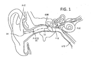
図1は、例示的な人間の耳の断面を示しており、いくつかの特徴部が識別されている。多くの異なる耳の大きさ及び幾何学的形状があり、図4に示されている例は単なる一例に過ぎない。図1に示すように、外耳道10は、可変断面積と通常真っ直ぐでない中心線12とを有する不規則な形状の円筒である。外耳道への入口14は、外耳道の壁が外耳道の中心線に対してあまり平行でない外耳道付近の外耳道の部分を指す。上記のように、人間の耳の正確な構造は、個人によって大きく異なる。例えば、図1の断面図において、外耳道10の中心線12に対して非平行である外耳道壁から外耳道10の中心線12にほぼ平行な壁までの比較的緩やかな移行が存在するので、図1の外耳道への入口14は比較的長い。他の例示的な幾何学的形状では、入口は、外耳道の中心線に対して非平行である壁から外耳道の中心線にほぼ平行な壁へのより急激な移行を呈し得るので、図1に示す入口より比較的短い場合もある。
FIG. 1 shows a cross section of an exemplary human ear, in which several features have been identified. There are many different ear sizes and geometries, and the example shown in FIG. 4 is merely an example. As shown in FIG. 1, the
外耳道の長さ及び幅は共に外耳道の共振特性に影響する。同様に、外耳道の入口の形状は、外耳道の後部の鼓膜に対する音響イヤーピースの配置に影響し得るので、入口14の形状も、耳内デバイスが外耳道に隣接して配置される際に、外耳道の共振特性に影響し得る。
Both the length and width of the ear canal affect the resonance characteristics of the ear canal. Similarly, because the shape of the ear canal entrance can affect the placement of the acoustic earpiece relative to the posterior tympanic membrane of the ear canal, the shape of the
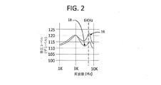
図2は、図3に示す例示的なイヤーピースのような例示的なイヤーピースの使用者の耳での音響音圧レベル(デシベル)対音の周波数(Hz)を示すグラフである。グラフは、イヤーピースが使用者の外耳道の入口に結合されている際の鼓膜での音圧レベルを示めす。図2の線16は、従来のイヤーピースの音量レベルを示している。図2に示すように、従来のイヤーピースは、約3KHzの第1の比較的強い共振と、約6KHzの第2の比較的強い共振と、を示す。3KHzの共振スパイクは、イヤーピースの音響ドライバの共振と関連し、6KHの共振スパイクは、使用者の外耳道の共振と関連する。
FIG. 2 is a graph illustrating acoustic sound pressure level (in decibels) versus frequency (Hz) at a user's ear of an example earpiece, such as the example earpiece shown in FIG. The graph shows the sound pressure level at the eardrum when the earpiece is coupled to the user's ear canal entrance.
図2の線18は、音響ノズルの各端部にインピーダンスが分配され、音響ノズルの容積が、この例では約3KHz及び6KHzを中心とする選択された周波数帯域で共振を制御するように調整される場合の例示的な音圧レベルを示す。図2に示すように、3KHzでの共振が依然として発生し、6KHzでの共振スパイクはまだ存在するが、スパイク(共振帯域内の音量増加)の大きさは従来のイヤーピースの共振スパイクよりも著しく小さい。例えば、図2に示されているように、約6KHzでの共振スパイクは、従来の共振レベルよりも7デシベル程度低く、さらに、その中心周波数に対する共振帯域幅の尺度である、より低いQ値を有する。従って、以下に説明するように、音響ノズルの両端に音響インピーダンスを加え、音響ノズルの容積を調整することにより、使用者の外耳道にしっかりと結合される耳内イヤーピースに実装される際のドライバの共振及び使用者の外耳道内の共振に関連する使用者に知覚される音レベルの不均一性を大幅に低減することができる。
具体的には、図2のグラフに示すように、3kHzの共振にほとんど影響を与えずに、出力を低減し、6kHzの共振を減衰させるために、ノズルの形状およびインピーダンスが使用され得る。両方の場合において、ノズルは、同一の全集中要素ノズルのインピーダンスを有する。相違点は、従来の場合(線16)、全ての純抵抗性インピーダンスは、ノズルの一端に位置され、一方、線18で示すように、抵抗性インピーダンスをノズルの両端に分配することによって、6KHz辺りの共振スパイクが得られ得る。
Specifically, as shown in the graph of FIG. 2, the nozzle shape and impedance can be used to reduce the output and attenuate the 6 kHz resonance with little effect on the 3 kHz resonance. In both cases, the nozzles have the same total lumped element nozzle impedance. The difference is that in the conventional case (line 16), all pure resistive impedance is located at one end of the nozzle, while 6KHz is distributed by distributing the resistive impedance across the nozzle as shown by
特定の例示的なイヤーピースの追加の詳細が、図3〜図9に関連してここで提供される。他の実施例は、耳内デバイスとして設計された他の物理的形状のイヤーピースを使用し得る。 Additional details of certain exemplary earpieces are now provided in connection with FIGS. Other embodiments may use other physical shaped earpieces designed as in-ear devices.
図3は、イヤーピース20の一例を示す。イヤーピース20は、ケーブル等を位置決めするためのステム22、音響ドライバモジュール24、及び、先端部26(図4A〜図4C及び図5A〜図5Bにおいてより明確に特定される)を含み得る。先端部26は、使用者の外耳道10に入口14を係合させるためのシーリング構造34を含む。いくつかのイヤーピースは、ステム22を欠いてもよいが、外部デバイスと無線通信するための電子モジュール(図示せず)を含み得る。先端部26は、この例では外側脚部30及び内側脚部32を含む位置決め保持構造28を含む。この実施例では、位置決め保持構造28は、耳当てを使用者の耳に対して保持するように設計されている。
FIG. 3 shows an example of the
図示された例における位置決め保持構造28は、使用者の外耳の内面の1つ以上の部分に係合するように設計されている。この例では、イヤーピース20は、耳の中に配置され、位置決め及び保持構造が使用者の耳に係合することを可能にするように捻られるように設計されている。このようにして、イヤーピースは、構造28及びイヤーピースの他の部分を位置決めして保持することによって、定位され、適所に保持される。
The positioning and holding
他の例のイヤーピースは、使用者の耳の他の側面と係合するように設計され得る。例えば、イヤーピースは、代わりに、使用者の耳の上部または後方部分の周りに延在するループを含むように形成され得る。別の例では、シーリング構造34と外耳道10への入口14との間の摩擦嵌合を使用して、イヤーピース20を使用者の耳の中に保持することができる。従って、位置決め及び保持構造を形成する多くの異なる方法を、異なる例示的なイヤーピースに関連して利用し得る。
Other example earpieces may be designed to engage other sides of the user's ear. For example, the earpiece may instead be formed to include a loop that extends around the upper or rear portion of the user's ear. In another example, a friction fit between the sealing
シーリング構造34は、音響ドライバモジュール24内の音響ドライバ50(図6参照)によって生成された音を使用者が聴くことができるように、イヤーピース20を使用者の外耳道に連結するように構成される。上述したように、イヤーピースが適切に配向されているとき、シーリング構造34は、入口14を外耳道10に係合させて、音響ドライバモジュール24内の音響ドライバによって生成された音を外耳道に伝えることができるように方向付けられ、この音がイヤーピース20を使用する人によって知覚され得る。
The sealing
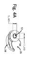
また、図4A〜図4Cは、イヤーピース20のイヤーピース先端部26の一例を示す図である。先端部26は、図1に示す音響ドライバモジュール24及びステム22に接続されている。イヤーピース先端部26の全ての要素が全ての図において特定されるわけではない。図4A〜図4Cに示すように、先端部26は、本体36と、位置決め保持構造28と、を含む。本体36は、音響ドライバモジュール24(図2参照)に接続し、シーリング構造34を担持する。通路38が、音響ドライバモジュールに接続されている後部領域から先端部26を貫通して形成される。通路38は、本体36を通って、シーリング構造34のより小さい端部42の出力開口55まで延在する。通路38は、音響ドライバモジュール24内の音響ドライバによって生成された音波を使用者の外耳道に伝導するように形成される。
4A to 4C are diagrams illustrating an example of the
シーリング構造34は円錐台構造を備える。円錐台構造は(図4Aに示すように)楕円形または長円形の断面を有し、(図4B、図4C、図5A、及び図5Bに示されるように)略直線状に先細になる壁を有する。一実施例では、シーリング構造の形状及びシーリング構造を形成する材料は、図4Cの矢印40の方向で測定した際に0.2gf/mm〜2gf/mmの範囲の剛性を生じさせるように作られる。シーリング構造のための適切な材料の例としては、シリコーン、TPU(熱可塑性ポリウレタン)及びTPE(熱可塑性エラストマー)が挙げられる。
The sealing
シーリング構造34のより小さい端部42は、殆どの使用者の外耳道10への入口14の内部に少量だけ嵌め込まれ、かつ、シーリング構造34が外耳道の入口に接触する、外耳道の内部には接触しないような寸法にされている。シーリング構造のより大きい端部44は、殆どの使用者の外耳道の入口よりも大きくなるような寸法にされている。
The
位置決め保持構造28及びシーリング構造34は、同じ材料、例えば30ショアA以下の硬度を有する非常に柔らかいシリコーンゴムで作られた単一部品であってもよい。シーリング構造34の壁46は、例えば壁の最も厚い部分で1mm未満といった非常に薄い均一な厚さであり得、円錐台構造のベース44に向かって先細であり得、外耳道の入口に大きな半径方向の圧力を及ぼすことなく、耳の輪郭に容易に合致し、良好な密封と良好な受動減衰をもたらす。イヤーピースの異なる部分が異なる機能を果たすので、イヤーピースの異なる部分が異なる材料、または異なる硬度または弾性率を有する材料で作られることが望ましい場合がある。例えば、位置決め保持構造28の硬度(デュロメータ)は、快適性(例えば、12ショアA)のために選択され得る。シーリング構造34の硬度は、より良好な嵌合及び密封のために、わずかに高く(例えば、20ショアA)てもよい。シーリング構造を本体36に機械的に連結するシーリング構造の部分の硬度は、より高く(例えば70ショアA)てもよい。シーリング構造34を本体36に連結するように設計された領域の硬度を高めることにより、シーリング構造34と本体36とのより確実な連結が可能になる。場合によっては、この領域の硬度を高めることによって、音波が進行する通路がより一定の形状及び寸法を有するようにでき得る。
The positioning and holding
また、図4A〜図4Cは、例示的なイヤーピース先端部26の外観図を示し、図5A及び図5Bは、例示的な実施例からの寸法を有するイヤーピース先端部26の断面図を示す。図4A〜図4C、図5A及び図5Bの実装形態では、シーリング構造34は楕円形であり、長軸7.69mm及び短軸42.83mmのより小さい端部42と、長軸16.1mm及び短軸14.2mmのより大きい端部44を有する。これらの寸法を有するシーリング構造は、多くの使用者の外耳道入口に適合して、小さい方の端部が外耳道に僅かに突出し、外耳道の壁とは接触しないようにする。より大きい端部は、外耳道には適合せず、従って、シーリング構造34は、外耳道の入口に係合する。子供を含めて、平均より小さい又は大きいサイズの耳を持つ使用者には、より小さいまたは大きいバージョンが使用され得る。同様の全体的な大きさであるが、長軸と短軸とのアスペクト比が異なるバージョンが、平均よりも円形に近い又は遠い外耳道入口を有する使用者に提供され得る。
4A-4C also show an external view of an
図6及び図7A〜図7Dは、使用者の外耳道内の共振を調整するように設計された音響ノズル57と音響通信する音響ドライバ50を有する音響イヤーピースのいくつかの例示的な構成を示す。音響ノズル57は、音響ドライバモジュール24の音響ドライバ50を収容する、音響ドライバチャンバ53に近接する入口開口51と、音響ドライバチャンバに対して入口開口51から遠位に形成された出力開口55と、の間を相互接続する。図6及び図7A〜図7Dに示す例では、音響ドライバ50に近接する音響ノズルの入口開口51に第1の音響メッシュ54が設けられ、音響ドライバ50から遠位の音響ノズル57の出力開口に第2の音響メッシュ56が設けられる。ドライバ50の前面と第1の音響メッシュ54との間には、キャビティ63(図8参照)が存在し得る。ある実施例では、第1及び第2の音響メッシュは、ノズルの始端及び終端に配置され、イヤー先端部34の柔軟部分42は、ノズル57の出力開口55を超えて延在する。図7Aは、ノズルが、より軟質シーリング構造34を形成するより軟質の材料に接続され且つそれによって囲まれた、より剛性の構造として形成されている実施例を示す。以下に説明する図9は同様の構成を示す。
6 and 7A-7D illustrate several exemplary configurations of an acoustic earpiece having an
図8は、イヤーピースの音響アーキテクチャの一例を示す。図8に示す例では、イヤーピースは、イヤホン100及びイヤー先端部110を含む。イヤー先端部110は、例えば、シーリング構造34として実装され得る。イヤホン100は、電子部品及び音を生成するドライバ50を含む。イヤホン100は、ドライバを耳の先端に接続するノズル57をさらに含む。
FIG. 8 shows an example of the acoustic architecture of the earpiece. In the example shown in FIG. 8, the earpiece includes an
ドライバ50は、第1の容積Vfcを有する前方キャビティ63と、第2の容積Vbcを有する後方キャビティ67と、を含むドライバキャビティ内に収容される。いくつかの実施例では、前方キャビティの開口は、ドライバキャビティをノズル57と接続するように構成される。いくつかの実施例では、前方キャビティの開口は、ドライバ50のダイヤフラム70の中央辺りに配置されて、前方キャビティをノズルと接続する。ノズルは、円錐形の容積であり、入口開口51から出力開口55まで延在し得る。
第1の音響メッシュ54の音響インピーダンス、第2の音響メッシュ56の音響インピーダンス、及び、音響ノズル57の容積58は、図2に示されるように、約3KHz及び6KHzでの共振を制御するように調整される。例えば、図2に示すように、3KHzの共振スパイクの形状は、ノズルの入口開口と出力開口の両方にメッシュを含めることによって狭められ得る。同様に、6KHzの周波数帯域では、共振スパイクの大きさは、ノズルの入口開口と出力開口の両方にメッシュを含めることによって著しく低下され得る。
The acoustic impedance of the first
図9に示すように、一実施例では、音響ノズル57への入口キャビティ69は、音響ドライバ50の近位に設けられ得る。例えば、入口キャビティ69は、ノズル57の5mm2の入口開口へ移行するドライバキャビティ63の前に25mm3の容積として形成され得る。図9に示す実施例では、ノズル57の出力開口55は、5mm2入口開口51よりもかなり大きい。例えば、出力開口55は、約10mm2であり得る。
As shown in FIG. 9, in one embodiment, an
音響ドライバの近位の音響メッシュ54及び音響ドライバの遠位の音響メッシュ56は、同じ材料から形成されても、又は、異なる材料から形成されてもよい。一実施例では、音響ドライバの近位の音響メッシュ54は、この周波数帯域における知覚される共振を低減するために、3KHzを包含する帯域内の音を優先的に減衰するように選択される。一の実施例では、使用され得る音響材料の例は、約5.2x10⁷kg/s*m4(音響オーム)の音響インピーダンスをもたらす5mm2の露出面積を有する260MKSのレイシルインピーダンスを有する。他の実施例では、音響メッシュ54は、1×107〜2.6×108kg/sm4の範囲の音響インピーダンスを有する音響材料を使用して形成され得る。
The acoustic driver proximal
一実施例では、音響ドライバの遠位の音響メッシュ56は、この周波数帯域における知覚される共振を低減するために、6KHzを包含する帯域内の音を優先的に減衰するように選択され、イヤーピースの所望の音響レスポンスを提供する。一の実施例では、使用され得る音響材料の例は、約8.5x10⁷kg/s*m4(音響オーム)の音響インピーダンスをもたらす10mm2の露出面積を有する850MKSのレイシルインピーダンスを有する。他の実施例では、音響メッシュ56は、1×107〜4×108kg/sm4の範囲の音響インピーダンスを有する音響材料を使用して形成され得る。
In one embodiment, the acoustic driver's distal
一実施例では、第1の音響メッシュ54と第2の音響メッシュ56との間のノズル容積58は約47mm3であり、長さは約10mmである。他の実施例では、容積は15mm3から250mm3まで様々であり、長さは4mmから20mmの範囲であり得る。いくつかの実施例では、ノズル容積は、入口開口51の直径が出力開口55の直径よりも小さい円錐容積である。
In one embodiment, the
音響メッシュ54,56は平面であり得、又は、随意的に、音響ノズルの中心軸から垂直な方向に延在する線の周りに湾曲して円筒部分を形成する平面メッシュであり得る。シーリング構造34の出力開口52が楕円形である場合、音響メッシュがその周りに湾曲する線は、楕円の長軸に対応し得、楕円の短軸に対応し得、いずれの軸にも対応しなくてもよい。音響メッシュが湾曲して円筒部分を形成するとき、メッシュの曲率半径は、一実施例では12mmであってもよい。他の実施例では、メッシュの曲率半径は、2mm〜100mmの範囲の曲率半径を使用して実施し得る。
The acoustic meshes 54, 56 can be planar or, optionally, can be planar meshes that curve around a line extending in a direction perpendicular to the central axis of the acoustic nozzle to form a cylindrical portion. When the
図7A〜図7Dは、音響メッシュ54,56の例示的なプロファイルを示す。図7Aに示す例では、音響メッシュ54は、音響ドライバ50から見て表面が凹状になるように円筒部分を形成するように湾曲される平面から形成される。この方向の曲率は、ここでは「音響ドライバの方向において凹状」と称する。音響ドライバ50から見て表面が凸面となるように一方向に湾曲される平面からなる音響メッシュを、ここでは、「音響ドライバの方向において凸状」であると称される。図7A〜図7Dに示されるように音響メッシュを湾曲して形成することは、音響メッシュに追加の剛性をもたらすことによって音響メッシュが機械的に共振するのを防止するのに役立つ。
7A-7D show exemplary profiles of the
音響メッシュを形成する多くの方法が実施され得る。図7Aに示される例では、音響メッシュ54は音響ドライバの方向おいてに凹状であり、音響メッシュ56も音響ドライバの方向において凹状である。図7Bに示される例では、音響メッシュ54は音響ドライバの方向において凹状であり、音響メッシュ56は音響ドライバの方向において凸状である。図7Cに示される例では、音響メッシュ54は音響ドライバの方向において凸状であり、音響メッシュ56は音響ドライバの方向において凹状である。図7Dに示される例では、音響メッシュ54は音響ドライバの方向において凸状であり、音響メッシュ56も音響ドライバの方向において凸状である。
Many methods for forming an acoustic mesh can be implemented. In the example shown in FIG. 7A, the
多くの実施例が説明されている。それにもかかわらず、本明細書に記載された本発明の概念の範囲から逸脱することなく追加の修正を行うことができ、従って、他の実装形態も特許請求の範囲内にあることが理解されるだろう。 A number of embodiments have been described. Nevertheless, it will be understood that additional modifications may be made without departing from the scope of the inventive concepts described herein, and that other implementations are within the scope of the claims. It will be.
10 外耳道
12 中心線
14 入口
16 線
18 線
20 イヤーピース
22 ステム
24 音響ドライバモジュール
26 先端部
28 位置決め保持構造
30 外側脚部
32 内側脚部
34 シーリング構造
36 本体
38 通路
42 端部
42 柔軟部分
44 端部
46 壁
50 音響ドライバ
51 入口開口
53 音響ドライバチャンバ
54 音響メッシュ
55 出力開口
56 音響メッシュ
57 音響ノズル
58 ノズル容積
63 前方キャビティ、ドライバキャビティ
67 後方キャビティ
69 入口キャビティ
70 ダイヤフラム
100 イヤホン
110 イヤー先端部
DESCRIPTION OF
Claims (21)
前記音響ドライバから出力開口に向かって延在する音響ノズルであって、前記音響ノズルは、前記音響ドライバからの音波を前記出力開口に向かって導くための、入口開口と前記出力開口との間の音響通路を含み、前記音響通路は、前記音響ドライバに隣接する近位端と、前記出力開口に向かう遠位端と、を有する、音響ノズルと;
使用者の外耳道の入口に係合するシーリング構造と;
前記音響ノズルの近位端における第1の音響インピーダンス;及び、
音響ノズルの遠位端における第2の音響インピーダンス;
を備えるイヤーピースであって、
前記音響ノズルは、前記第1の音響インピーダンスと前記第2の音響インピーダンスとの間にノズル容積を有し、前記第1の音響インピーダンス、前記第2の音響インピーダンス、及び、前記ノズル容積は、前記シーリング構造が前記使用者の外耳道の入口に係合された際に、前記使用者の外耳道における共振を制御するように選択されており、
前記第1の音響インピーダンスは、前記音響ノズルの中心軸から垂直な方向に延在する線の周りに湾曲して、円筒の部分を形成する第1の音響材料で形成された第1の音響メッシュであることを特徴とするイヤーピース。 With an acoustic driver;
An acoustic nozzle extending from the acoustic driver toward the output opening, the acoustic nozzle between the inlet opening and the output opening for directing sound waves from the acoustic driver toward the output opening; An acoustic nozzle, including an acoustic passage, the acoustic passage having a proximal end adjacent to the acoustic driver and a distal end toward the output opening;
A sealing structure that engages the entrance of the user's ear canal;
A first acoustic impedance at a proximal end of the acoustic nozzle; and
A second acoustic impedance at the distal end of the acoustic nozzle;
An earpiece comprising
The acoustic nozzle has a nozzle volume between the first acoustic impedance and the second acoustic impedance, and the first acoustic impedance, the second acoustic impedance, and the nozzle volume are Selected to control resonance in the user's ear canal when a sealing structure is engaged to the user's ear canal entrance ;
The first acoustic impedance is a first acoustic mesh formed of a first acoustic material that is curved around a line extending in a direction perpendicular to the central axis of the acoustic nozzle to form a cylindrical portion. earpiece, characterized in that it.
前記出力開口に隣接する領域から延在し、使用者の外耳道の入口に隣接する前記出力開口を保持するシーリング構造と;
前記音響ドライバから前記出力開口に向かって延在する音響ノズルであって、前記音響ノズルは、前記音響ドライバからの音波を前記出力開口に向かって導くための、入口開口と前記出力開口との間の音響通路を含み、前記音響通路は、前記音響ドライバに隣接する近位端と、前記出力開口に向かう遠位端と、を有する、音響ノズルと;
前記音響ノズルの近位端における第1の音響インピーダンス;及び、
音響ノズルの遠位端における第2の音響インピーダンス;
を備えるイヤーピースであって、
前記音響ノズルは、前記第1の音響インピーダンスと前記第2の音響インピーダンスとの間にノズル容積を有し、前記第1の音響インピーダンス、前記第2の音響インピーダンス、及び、前記ノズル容積は、前記シーリング構造が前記使用者の外耳道の入口に係合された際に、前記使用者の外耳道における共振を制御するように選択されており、
前記第1の音響インピーダンスは、前記第2の音響インピーダンスとは異なる音響インピーダンスを有し、
前記第1の音響インピーダンスは、前記音響ノズルの中心軸から垂直な方向に延在する線の周りに湾曲して、円筒の部分を形成する第1の音響材料で形成された第1の音響メッシュであることを特徴とするイヤーピース。 A body having an acoustic driver and an output aperture;
A sealing structure extending from a region adjacent to the output opening and retaining the output opening adjacent to the user's ear canal entrance;
An acoustic nozzle extending from the acoustic driver toward the output opening, wherein the acoustic nozzle is between the inlet opening and the output opening for guiding sound waves from the acoustic driver toward the output opening. An acoustic nozzle having a proximal end adjacent to the acoustic driver and a distal end toward the output opening;
A first acoustic impedance at a proximal end of the acoustic nozzle; and
A second acoustic impedance at the distal end of the acoustic nozzle;
An earpiece comprising
The acoustic nozzle has a nozzle volume between the first acoustic impedance and the second acoustic impedance, and the first acoustic impedance, the second acoustic impedance, and the nozzle volume are Selected to control resonance in the user's ear canal when a sealing structure is engaged to the user's ear canal entrance;
Said first acoustic impedance, have a different acoustic impedance than the second acoustic impedance,
The first acoustic impedance is a first acoustic mesh formed of a first acoustic material that is curved around a line extending in a direction perpendicular to the central axis of the acoustic nozzle to form a cylindrical portion. earpiece, characterized in that it.
音波を音響ドライバから出力開口に向かって伝導する音響通路であって、前記音響ドライバに隣接するように構成された近位端、及び、前記出力開口に隣接するように構成された遠位端を有する音響通路;
前記音響ノズルの近位端における第1音響インピーダンス手段;及び、
前記音響ノズルの遠位端における第2音響インピーダンス手段;
を備え、
前記音響ノズルは、第1の音響インピーダンスと第2の音響インピーダンスとの間にノズル容積を有し、前記第1の音響インピーダンス、前記第2の音響インピーダンス、及び、前記ノズル容積は、約3KHzを中心とする第1の周波数帯域における、かつ、約6KHzを中心とする第2の周波数帯域における共振を制御するように選択されており、
前記第1の音響インピーダンスは、前記音響ノズルの中心軸から垂直な方向に延在する線の周りに湾曲して、円筒の部分を形成する第1の音響材料で形成された第1の音響メッシュであることを特徴とする音響ノズル。 An acoustic nozzle for an earpiece,
An acoustic path for conducting sound waves from an acoustic driver toward an output opening, comprising a proximal end configured to be adjacent to the acoustic driver and a distal end configured to be adjacent to the output opening An acoustic passage having;
First acoustic impedance means at the proximal end of the acoustic nozzle; and
Second acoustic impedance means at the distal end of the acoustic nozzle;
With
The acoustic nozzle has a nozzle volume between a first acoustic impedance and a second acoustic impedance, and the first acoustic impedance, the second acoustic impedance, and the nozzle volume are about 3 KHz. Selected to control resonance in a first frequency band centered and in a second frequency band centered around 6 KHz ;
The first acoustic impedance is a first acoustic mesh formed of a first acoustic material that is curved around a line extending in a direction perpendicular to the central axis of the acoustic nozzle to form a cylindrical portion. acoustic nozzles, characterized in that it.
Applications Claiming Priority (3)
| Application Number | Priority Date | Filing Date | Title |
|---|---|---|---|
| US14/641,391 | 2015-03-08 | ||
| US14/641,391 US9615158B2 (en) | 2015-03-08 | 2015-03-08 | Earpiece |
| PCT/US2016/021173 WO2016144866A1 (en) | 2015-03-08 | 2016-03-07 | Earpiece |
Publications (2)
| Publication Number | Publication Date |
|---|---|
| JP2018508158A JP2018508158A (en) | 2018-03-22 |
| JP6557351B2 true JP6557351B2 (en) | 2019-08-07 |
Family
ID=55629111
Family Applications (1)
| Application Number | Title | Priority Date | Filing Date |
|---|---|---|---|
| JP2017547139A Expired - Fee Related JP6557351B2 (en) | 2015-03-08 | 2016-03-07 | Earpiece |
Country Status (5)
| Country | Link |
|---|---|
| US (2) | US9615158B2 (en) |
| EP (1) | EP3269148B1 (en) |
| JP (1) | JP6557351B2 (en) |
| CN (1) | CN107548561B (en) |
| WO (1) | WO2016144866A1 (en) |
Families Citing this family (9)
| Publication number | Priority date | Publication date | Assignee | Title |
|---|---|---|---|---|
| US10595111B2 (en) * | 2017-03-20 | 2020-03-17 | Bose Corporation | Earbud frame for acoustic driver and complimentary ear tip |
| US11115752B2 (en) * | 2017-10-11 | 2021-09-07 | Institut Für Rundfunktechnik | Sound transducer |
| KR101952906B1 (en) * | 2017-12-20 | 2019-02-28 | 부전전자 주식회사 | Acoustic device having multiple vibration plates |
| USD875071S1 (en) * | 2018-10-15 | 2020-02-11 | Shenzhen Aukey Smart Information Technology Co., Ltd. | Headset for telephones |
| US10820084B2 (en) * | 2019-01-07 | 2020-10-27 | Bose Corporation | Ear tip sealing structure |
| US10999670B2 (en) | 2019-01-07 | 2021-05-04 | Bose Corporation | Ear tip sealing structure |
| EP3739904A1 (en) * | 2019-05-14 | 2020-11-18 | FRAUNHOFER-GESELLSCHAFT zur Förderung der angewandten Forschung e.V. | Acoustic bending converter system and acoustic device |
| GB2586063A (en) * | 2019-08-01 | 2021-02-03 | Drown Ltd | Modular earphone |
| CN111787472B (en) * | 2020-08-28 | 2022-03-22 | 歌尔光学科技有限公司 | Sound production structure, audio equipment and wear display device |
Family Cites Families (21)
| Publication number | Priority date | Publication date | Assignee | Title |
|---|---|---|---|---|
| US5887070A (en) | 1992-05-08 | 1999-03-23 | Etymotic Research, Inc. | High fidelity insert earphones and methods of making same |
| US6567525B1 (en) | 1994-06-17 | 2003-05-20 | Bose Corporation | Supra aural active noise reduction headphones |
| US7240765B2 (en) * | 2004-08-25 | 2007-07-10 | Phonak Ag | Customized hearing protection earplug with an acoustic filter and method for manufacturing the same |
| US8111854B2 (en) | 2006-11-29 | 2012-02-07 | Yan-Ru Peng | Methods and apparatus for sound production |
| US8249287B2 (en) | 2010-08-16 | 2012-08-21 | Bose Corporation | Earpiece positioning and retaining |
| US8594351B2 (en) | 2006-06-30 | 2013-11-26 | Bose Corporation | Equalized earphones |
| US7916888B2 (en) | 2006-06-30 | 2011-03-29 | Bose Corporation | In-ear headphones |
| JP2008283326A (en) * | 2007-05-09 | 2008-11-20 | Nappu Enterprise Kk | Earphone microphone |
| JP2009031238A (en) * | 2007-06-29 | 2009-02-12 | Optical Comb Inc | Optical coherence tomography device |
| JP4823362B2 (en) * | 2007-09-07 | 2011-11-24 | パイオニア株式会社 | earphone |
| US8265316B2 (en) | 2008-03-20 | 2012-09-11 | Siemens Medical Instruments Pte. Ltd. | Hearing aid with enhanced vent |
| EP2283659A1 (en) | 2008-05-21 | 2011-02-16 | Phonak AG | Earphone system and use of an earphone system |
| US8737664B2 (en) | 2008-06-18 | 2014-05-27 | Apple Inc. | In-the-ear porting structures for earbud |
| DE102009008376A1 (en) | 2009-02-11 | 2010-08-12 | Sennheiser Electronic Gmbh & Co. Kg | receiver |
| WO2012165976A1 (en) | 2011-06-01 | 2012-12-06 | Phitek Systems Limited | In-ear device incorporating active noise reduction |
| US8737669B2 (en) | 2011-07-28 | 2014-05-27 | Bose Corporation | Earpiece passive noise attenuating |
| US9082388B2 (en) * | 2012-05-25 | 2015-07-14 | Bose Corporation | In-ear active noise reduction earphone |
| US9269342B2 (en) | 2012-05-25 | 2016-02-23 | Bose Corporation | In-ear active noise reduction earphone |
| US8976994B2 (en) | 2012-06-20 | 2015-03-10 | Apple Inc. | Earphone having an acoustic tuning mechanism |
| US8971561B2 (en) | 2012-06-20 | 2015-03-03 | Apple Inc. | Earphone having a controlled acoustic leak port |
| US8670586B1 (en) | 2012-09-07 | 2014-03-11 | Bose Corporation | Combining and waterproofing headphone port exits |
-
2015
- 2015-03-08 US US14/641,391 patent/US9615158B2/en active Active
-
2016
- 2016-03-07 JP JP2017547139A patent/JP6557351B2/en not_active Expired - Fee Related
- 2016-03-07 EP EP16711932.0A patent/EP3269148B1/en active Active
- 2016-03-07 CN CN201680023014.2A patent/CN107548561B/en not_active Expired - Fee Related
- 2016-03-07 WO PCT/US2016/021173 patent/WO2016144866A1/en active Application Filing
-
2017
- 2017-02-17 US US15/435,739 patent/US9860624B2/en not_active Expired - Fee Related
Also Published As
| Publication number | Publication date |
|---|---|
| EP3269148A1 (en) | 2018-01-17 |
| WO2016144866A1 (en) | 2016-09-15 |
| US9860624B2 (en) | 2018-01-02 |
| US20160261944A1 (en) | 2016-09-08 |
| US9615158B2 (en) | 2017-04-04 |
| JP2018508158A (en) | 2018-03-22 |
| EP3269148B1 (en) | 2020-05-06 |
| CN107548561A (en) | 2018-01-05 |
| CN107548561B (en) | 2020-01-21 |
| US20170164093A1 (en) | 2017-06-08 |
Similar Documents
| Publication | Publication Date | Title |
|---|---|---|
| JP6557351B2 (en) | Earpiece | |
| JP6394827B2 (en) | Sound output device | |
| JP6644858B2 (en) | Earpiece positioning and holding structure | |
| EP2737720B1 (en) | Earpiece passive noise attenuating | |
| ES2755003T5 (en) | Ear piece to attenuate sound | |
| US9813794B2 (en) | Noise reduction with in-ear headphone | |
| US20120039501A1 (en) | Earpiece positioning and retaining | |
| US11381897B2 (en) | Variable eartip for earphone |
Legal Events
| Date | Code | Title | Description |
|---|---|---|---|
| A621 | Written request for application examination |
Free format text: JAPANESE INTERMEDIATE CODE: A621 Effective date: 20171107 |
|
| A977 | Report on retrieval |
Free format text: JAPANESE INTERMEDIATE CODE: A971007 Effective date: 20181024 |
|
| A131 | Notification of reasons for refusal |
Free format text: JAPANESE INTERMEDIATE CODE: A131 Effective date: 20181029 |
|
| A521 | Request for written amendment filed |
Free format text: JAPANESE INTERMEDIATE CODE: A523 Effective date: 20190128 |
|
| TRDD | Decision of grant or rejection written | ||
| A01 | Written decision to grant a patent or to grant a registration (utility model) |
Free format text: JAPANESE INTERMEDIATE CODE: A01 Effective date: 20190617 |
|
| A61 | First payment of annual fees (during grant procedure) |
Free format text: JAPANESE INTERMEDIATE CODE: A61 Effective date: 20190711 |
|
| R150 | Certificate of patent or registration of utility model |
Ref document number: 6557351 Country of ref document: JP Free format text: JAPANESE INTERMEDIATE CODE: R150 |
|
| R250 | Receipt of annual fees |
Free format text: JAPANESE INTERMEDIATE CODE: R250 |
|
| LAPS | Cancellation because of no payment of annual fees |