JP6553371B2 - Fuel cell vehicle - Google Patents
Fuel cell vehicle Download PDFInfo
- Publication number
- JP6553371B2 JP6553371B2 JP2015025256A JP2015025256A JP6553371B2 JP 6553371 B2 JP6553371 B2 JP 6553371B2 JP 2015025256 A JP2015025256 A JP 2015025256A JP 2015025256 A JP2015025256 A JP 2015025256A JP 6553371 B2 JP6553371 B2 JP 6553371B2
- Authority
- JP
- Japan
- Prior art keywords
- fuel cell
- width direction
- opening
- vehicle
- vehicle width
- Prior art date
- Legal status (The legal status is an assumption and is not a legal conclusion. Google has not performed a legal analysis and makes no representation as to the accuracy of the status listed.)
- Active
Links
Images


Classifications
-
- H—ELECTRICITY
- H01—ELECTRIC ELEMENTS
- H01M—PROCESSES OR MEANS, e.g. BATTERIES, FOR THE DIRECT CONVERSION OF CHEMICAL ENERGY INTO ELECTRICAL ENERGY
- H01M8/00—Fuel cells; Manufacture thereof
- H01M8/04—Auxiliary arrangements, e.g. for control of pressure or for circulation of fluids
- H01M8/04082—Arrangements for control of reactant parameters, e.g. pressure or concentration
- H01M8/04201—Reactant storage and supply, e.g. means for feeding, pipes
-
- H—ELECTRICITY
- H01—ELECTRIC ELEMENTS
- H01M—PROCESSES OR MEANS, e.g. BATTERIES, FOR THE DIRECT CONVERSION OF CHEMICAL ENERGY INTO ELECTRICAL ENERGY
- H01M8/00—Fuel cells; Manufacture thereof
- H01M8/02—Details
- H01M8/0202—Collectors; Separators, e.g. bipolar separators; Interconnectors
- H01M8/0267—Collectors; Separators, e.g. bipolar separators; Interconnectors having heating or cooling means, e.g. heaters or coolant flow channels
-
- H—ELECTRICITY
- H01—ELECTRIC ELEMENTS
- H01M—PROCESSES OR MEANS, e.g. BATTERIES, FOR THE DIRECT CONVERSION OF CHEMICAL ENERGY INTO ELECTRICAL ENERGY
- H01M8/00—Fuel cells; Manufacture thereof
- H01M8/04—Auxiliary arrangements, e.g. for control of pressure or for circulation of fluids
- H01M8/04082—Arrangements for control of reactant parameters, e.g. pressure or concentration
- H01M8/04089—Arrangements for control of reactant parameters, e.g. pressure or concentration of gaseous reactants
-
- H—ELECTRICITY
- H01—ELECTRIC ELEMENTS
- H01M—PROCESSES OR MEANS, e.g. BATTERIES, FOR THE DIRECT CONVERSION OF CHEMICAL ENERGY INTO ELECTRICAL ENERGY
- H01M8/00—Fuel cells; Manufacture thereof
- H01M8/24—Grouping of fuel cells, e.g. stacking of fuel cells
- H01M8/2457—Grouping of fuel cells, e.g. stacking of fuel cells with both reactants being gaseous or vaporised
-
- H—ELECTRICITY
- H01—ELECTRIC ELEMENTS
- H01M—PROCESSES OR MEANS, e.g. BATTERIES, FOR THE DIRECT CONVERSION OF CHEMICAL ENERGY INTO ELECTRICAL ENERGY
- H01M8/00—Fuel cells; Manufacture thereof
- H01M8/24—Grouping of fuel cells, e.g. stacking of fuel cells
- H01M8/2465—Details of groupings of fuel cells
- H01M8/247—Arrangements for tightening a stack, for accommodation of a stack in a tank or for assembling different tanks
- H01M8/2475—Enclosures, casings or containers of fuel cell stacks
-
- H—ELECTRICITY
- H01—ELECTRIC ELEMENTS
- H01M—PROCESSES OR MEANS, e.g. BATTERIES, FOR THE DIRECT CONVERSION OF CHEMICAL ENERGY INTO ELECTRICAL ENERGY
- H01M8/00—Fuel cells; Manufacture thereof
- H01M8/24—Grouping of fuel cells, e.g. stacking of fuel cells
- H01M8/2465—Details of groupings of fuel cells
- H01M8/2483—Details of groupings of fuel cells characterised by internal manifolds
-
- H—ELECTRICITY
- H01—ELECTRIC ELEMENTS
- H01M—PROCESSES OR MEANS, e.g. BATTERIES, FOR THE DIRECT CONVERSION OF CHEMICAL ENERGY INTO ELECTRICAL ENERGY
- H01M8/00—Fuel cells; Manufacture thereof
- H01M8/24—Grouping of fuel cells, e.g. stacking of fuel cells
- H01M8/2465—Details of groupings of fuel cells
- H01M8/2484—Details of groupings of fuel cells characterised by external manifolds
-
- H—ELECTRICITY
- H01—ELECTRIC ELEMENTS
- H01M—PROCESSES OR MEANS, e.g. BATTERIES, FOR THE DIRECT CONVERSION OF CHEMICAL ENERGY INTO ELECTRICAL ENERGY
- H01M8/00—Fuel cells; Manufacture thereof
- H01M8/10—Fuel cells with solid electrolytes
- H01M2008/1095—Fuel cells with polymeric electrolytes
-
- H—ELECTRICITY
- H01—ELECTRIC ELEMENTS
- H01M—PROCESSES OR MEANS, e.g. BATTERIES, FOR THE DIRECT CONVERSION OF CHEMICAL ENERGY INTO ELECTRICAL ENERGY
- H01M2250/00—Fuel cells for particular applications; Specific features of fuel cell system
- H01M2250/20—Fuel cells in motive systems, e.g. vehicle, ship, plane
-
- Y—GENERAL TAGGING OF NEW TECHNOLOGICAL DEVELOPMENTS; GENERAL TAGGING OF CROSS-SECTIONAL TECHNOLOGIES SPANNING OVER SEVERAL SECTIONS OF THE IPC; TECHNICAL SUBJECTS COVERED BY FORMER USPC CROSS-REFERENCE ART COLLECTIONS [XRACs] AND DIGESTS
- Y02—TECHNOLOGIES OR APPLICATIONS FOR MITIGATION OR ADAPTATION AGAINST CLIMATE CHANGE
- Y02E—REDUCTION OF GREENHOUSE GAS [GHG] EMISSIONS, RELATED TO ENERGY GENERATION, TRANSMISSION OR DISTRIBUTION
- Y02E60/00—Enabling technologies; Technologies with a potential or indirect contribution to GHG emissions mitigation
- Y02E60/30—Hydrogen technology
- Y02E60/50—Fuel cells
-
- Y—GENERAL TAGGING OF NEW TECHNOLOGICAL DEVELOPMENTS; GENERAL TAGGING OF CROSS-SECTIONAL TECHNOLOGIES SPANNING OVER SEVERAL SECTIONS OF THE IPC; TECHNICAL SUBJECTS COVERED BY FORMER USPC CROSS-REFERENCE ART COLLECTIONS [XRACs] AND DIGESTS
- Y02—TECHNOLOGIES OR APPLICATIONS FOR MITIGATION OR ADAPTATION AGAINST CLIMATE CHANGE
- Y02T—CLIMATE CHANGE MITIGATION TECHNOLOGIES RELATED TO TRANSPORTATION
- Y02T90/00—Enabling technologies or technologies with a potential or indirect contribution to GHG emissions mitigation
- Y02T90/40—Application of hydrogen technology to transportation, e.g. using fuel cells
Description
本発明は、複数の燃料電池が積層された燃料電池スタックをスタックケースに収納するとともに、前記スタックケースは、ダッシュボードの前方に形成されたフロントルーム内に搭載される燃料電池車両に関する。 The present invention relates to a fuel cell vehicle in which a fuel cell stack in which a plurality of fuel cells are stacked is housed in a stack case, and the stack case is mounted in a front room formed in front of a dashboard.
例えば、固体高分子型燃料電池は、高分子イオン交換膜からなる電解質膜の一方にアノード電極が、他方にカソード電極が、それぞれ配設された電解質膜・電極構造体(MEA)を備える。電解質膜・電極構造体は、セパレータによって挟持されることにより、発電セルが構成されている。この燃料電池は、通常、所定の数の発電セルを積層することにより、例えば、車載用燃料電池スタックとして燃料電池車両に搭載されている。 For example, a polymer electrolyte fuel cell includes an electrolyte membrane / electrode structure (MEA) in which an anode electrode is provided on one side of an electrolyte membrane made of a polymer ion exchange membrane and a cathode electrode is provided on the other side. The electrolyte membrane electrode assembly is sandwiched by the separators to constitute a power generation cell. This fuel cell is usually mounted on a fuel cell vehicle as an in-vehicle fuel cell stack, for example, by stacking a predetermined number of power generation cells.
燃料電池車両では、特に燃料ガスである水素が、燃料電池スタックを搭載する空間内に漏出するおそれがある。このため、燃料電池スタックから漏出した水素を外部に効率よく排出することを目的として、例えば、特許文献1に開示されている燃料電池自動車が提案されている。 In a fuel cell vehicle, hydrogen, which is a fuel gas in particular, may leak into the space in which the fuel cell stack is mounted. For this reason, for example, a fuel cell vehicle disclosed in Patent Document 1 has been proposed for the purpose of efficiently discharging hydrogen leaked from the fuel cell stack to the outside.
この燃料電池自動車は、乗員居室の前方に燃料電池を搭載する閉空間を配置している。そして、必要に応じて、閉空間の上部には、第1開口部が設けられるとともに、走行時に負圧が発生する位置には、第2開口部が設けられ、前記閉空間内に燃料電池システムから漏洩した水素を排出している。 In this fuel cell vehicle, a closed space in which the fuel cell is mounted is disposed in front of the passenger compartment. If necessary, a first opening is provided in the upper part of the closed space, and a second opening is provided at a position where negative pressure is generated during traveling, and the fuel cell system is provided in the closed space. The hydrogen leaked from the
従って、閉空間の上部に開口部を設けた場合には、特に車両停止状態において、閉空間内で燃料電池システムから漏出した水素を確実に車外に換気できる、としている。また、開口部を負圧の発生位置に設けた場合には、走行時に燃料電池システムから漏洩した水素を閉空間から排出することができる、としている。 Therefore, when an opening is provided in the upper part of the closed space, hydrogen leaked from the fuel cell system in the closed space can be surely ventilated outside the vehicle, particularly when the vehicle is stopped. In addition, when the opening is provided at the position where the negative pressure is generated, hydrogen leaked from the fuel cell system during traveling can be discharged from the closed space.
上記の特許文献1では、閉空間の上部に開口部が設けられている。このため、車両が前後に傾斜した際や、左右に傾斜した際に、水素が閉空間に残るおそれがある。従って、漏出した水素を確実に車外に換気することができないという問題がある。 In said patent document 1, the opening part is provided in the upper part of closed space. Therefore, hydrogen may remain in the closed space when the vehicle leans back and forth or when it leans left and right. Therefore, there is a problem that the leaked hydrogen cannot be reliably ventilated outside the vehicle.
本発明は、この種の問題を解決するものであり、簡単な構成で、スタックケース内に漏出した燃料ガスを、容易且つ確実に排出させることが可能な燃料電池車両を提供することを目的とする。 An object of the present invention is to solve this type of problem, and to provide a fuel cell vehicle capable of easily and reliably discharging fuel gas leaked into a stack case with a simple configuration. Do.
本発明に係る燃料電池車両は、燃料ガスと酸化剤ガスとの電気化学反応により発電する燃料電池が複数積層され、前記燃料ガスを前記燃料電池の積層方向に流通させる燃料ガス連通孔を備えた燃料電池スタックを備えている。燃料電池スタックは、平面視矩形状のスタックケースに収納されるとともに、前記スタックケースは、ダッシュボードの前方に形成されたフロントルーム内に搭載されている。そして、スタックケースの上面部には、少なくとも一方の対角位置に該スタックケース内を外部に連通する開口部が形成されている。 A fuel cell vehicle according to the present invention includes a plurality of fuel cells that generate power by an electrochemical reaction between a fuel gas and an oxidant gas, and includes fuel gas communication holes that allow the fuel gas to flow in the stacking direction of the fuel cells. It has a fuel cell stack. The fuel cell stack is housed in a rectangular stack case in plan view, and the stack case is mounted in a front room formed in front of the dashboard. In the upper surface portion of the stack case, an opening that communicates the inside of the stack case to the outside is formed at at least one diagonal position.
また、この燃料電池車両では、スタックケースの上面部には、一方の対角位置と他方の対角位置とに、それぞれ開口部が設けられることが好ましい。 In this fuel cell vehicle, it is preferable that openings are provided in the upper surface portion of the stack case at one diagonal position and the other diagonal position, respectively.
さらに、この燃料電池車両では、開口部に一端が接続されるダクト部材を備え、フロントルームの車幅方向両端部には、該フロントルームの外部に連通し、且つ前記開口部よりも上方に位置して排出口が設けられることが好ましい。その際、排出口には、ダクト部材の他端が接続されることが好ましい。 Further, the fuel cell vehicle includes a duct member having one end connected to the opening, and the both ends in the vehicle width direction of the front room communicate with the outside of the front room and are positioned above the opening. Preferably, an outlet is provided. In that case, it is preferable that the other end of the duct member is connected to the discharge port.
さらにまた、この燃料電池車両は、スタックケースの上面部は、燃料電池スタックが対向する内面が平坦面に形成されることが好ましい。 Furthermore, in the fuel cell vehicle, it is preferable that the upper surface of the stack case is formed to have a flat inner surface facing the fuel cell stack.
また、この燃料電池車両では、開口部は、燃料ガス連通孔の鉛直方向上方に配置されることが好ましい。 Further, in the fuel cell vehicle, the opening is preferably disposed vertically above the fuel gas communication hole.
さらに、この燃料電池車両では、スタックケースの下面部には、該スタックケース内に空気を導入する吸気用開口部が形成されることが好ましい。 Furthermore, in this fuel cell vehicle, it is preferable that an intake opening for introducing air into the stack case is formed on the lower surface of the stack case.
さらにまた、この燃料電池車両では、吸気用開口部は、スタックケースの車両前方側に少なくとも2個以上設けられることが好ましい。 Furthermore, in this fuel cell vehicle, it is preferable that at least two intake openings be provided on the vehicle front side of the stack case.
また、この燃料電池車両では、複数の吸気用開口部は、それぞれの断面積が異なることが好ましい。 Further, in the fuel cell vehicle, it is preferable that the plurality of intake openings have different cross-sectional areas.
さらに、この燃料電池車両では、燃料ガス連通孔側の吸気用開口部の断面積は、他の吸気用開口部の断面積よりも大きく設定されることが好ましい。 Furthermore, in this fuel cell vehicle, the cross-sectional area of the intake opening on the fuel gas communication hole side is preferably set larger than the cross-sectional area of the other intake openings.
本発明によれば、スタックケースの上面部には、対角位置に対応して該スタックケース内を外部に連通する少なくとも2個の開口部が形成されている。このため、スタックケース内を上昇する燃料ガスは、各開口部から排出されている。 According to the present invention, the upper surface portion of the stack case is formed with at least two openings that communicate with the inside of the stack case corresponding to the diagonal positions. For this reason, the fuel gas rising in the stack case is discharged from each opening.
さらに、車両が前後方向又は左右方向に傾斜しても、少なくとも一方の開口部から燃料ガスを排出させることができる。従って、簡単な構成で、スタックケース内に漏出した燃料ガスを、容易且つ確実に排出させることが可能になる。 Furthermore, even if the vehicle is inclined in the front-rear direction or in the left-right direction, the fuel gas can be discharged from at least one opening. Therefore, the fuel gas leaked into the stack case can be easily and reliably discharged with a simple configuration.
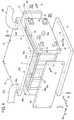
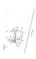
図1〜図3に示すように、本発明の第1の実施形態に係る燃料電池車両10は、例えば、燃料電池電気自動車である。燃料電池車両10は、燃料電池スタック12が収容されたスタックケース14をダッシュボード16の前方に形成されたフロントルーム(モータルーム)18内に配設する。
As shown in FIGS. 1 to 3, a
図4に示すように、燃料電池スタック12は、複数の燃料電池20が車両幅方向(矢印B方向)に積層される。燃料電池20の積層方向一端には、第1ターミナルプレート22a、第1絶縁プレート24a及び第1エンドプレート26aが、外方に向かって順次配設される。燃料電池20の積層方向他端には、第2ターミナルプレート22b、第2絶縁プレート24b及び第2エンドプレート26bが、外方に向かって順次配設される。燃料電池スタック12の車両幅方向両端には、第1エンドプレート26aと第2エンドプレート26bとが配置される。
As shown in FIG. 4, in the
第1エンドプレート26a及び第2エンドプレート26bは、燃料電池20、第1絶縁プレート24a及び第2絶縁プレート24bの外形寸法よりも大きな外形寸法に設定される。第1ターミナルプレート22aは、第1絶縁プレート24aの内部の凹部に収容される一方、第2ターミナルプレート22bは、第2絶縁プレート24bの内部の凹部に収容されてもよい。
The
横長形状の第1エンドプレート26aの中央部からは、第1ターミナルプレート22aに接続された第1電力出力端子28aが外方に向かって延在する。横長形状の第2エンドプレート26bの中央部からは、第2ターミナルプレート22bに接続された第2電力出力端子28bが外方に向かって延在する。第1エンドプレート26aと第2エンドプレート26bの各角部は、積層方向に延在するタイロッド30により固定され、前記積層方向に締め付け荷重が付与される。
A first
図5に示すように、燃料電池20は、電解質膜・電極構造体32が、第1セパレータ34及び第2セパレータ36に挟持される。第1セパレータ34及び第2セパレータ36は、金属セパレータ又はカーボンセパレータにより構成される。
As shown in FIG. 5, in the
燃料電池20の矢印A方向の一端縁部には、積層方向(矢印B方向)に互いに連通して、酸化剤ガス入口連通孔38a、冷却媒体入口連通孔40a及び燃料ガス出口連通孔42bが、矢印C方向(鉛直方向)に配列して設けられる。酸化剤ガス入口連通孔38aは、酸化剤ガス、例えば、酸素含有ガスを供給する。冷却媒体入口連通孔40aは、冷却媒体を供給する一方、燃料ガス出口連通孔42bは、燃料ガス、例えば、水素含有ガスを排出する。
At one end edge of the
燃料電池20の矢印A方向の他端縁部には、矢印B方向に互いに連通して、燃料ガスを供給する燃料ガス入口連通孔42a、冷却媒体を排出する冷却媒体出口連通孔40b及び酸化剤ガスを排出する酸化剤ガス出口連通孔38bが、矢印C方向に配列して設けられる。
The other end edge of the
第1セパレータ34の電解質膜・電極構造体32に向かう面には、酸化剤ガス入口連通孔38aと酸化剤ガス出口連通孔38bとに連通する酸化剤ガス流路44が設けられる。第2セパレータ36の電解質膜・電極構造体32に向かう面には、燃料ガス入口連通孔42aと燃料ガス出口連通孔42bとに連通する燃料ガス流路46が設けられる。
An oxidant gas flow path 44 communicating with the oxidant gas
互いに隣接し燃料電池20を構成する第1セパレータ34と第2セパレータ36との間には、冷却媒体入口連通孔40aと冷却媒体出口連通孔40bとを連通する冷却媒体流路48が設けられる。第1セパレータ34と第2セパレータ36とには、それぞれシール部材50、52が、一体的又は個別に設けられる。
Between the
電解質膜・電極構造体32は、例えば、パーフルオロスルホン酸の薄膜に水が含浸された固体高分子電解質膜54と、前記固体高分子電解質膜54を挟持するカソード電極56及びアノード電極58とを備える。カソード電極56及びアノード電極58は、カーボンペーパ等からなるガス拡散層と、白金合金が表面に担持された多孔質カーボン粒子が前記ガス拡散層の表面に一様に塗布されて形成される電極触媒層とを有する。電極触媒層は、固体高分子電解質膜54の両面に形成される。
The electrolyte membrane /
図4に示すように、第1エンドプレート26aの一方の対角位置には、酸化剤ガス入口連通孔38aに連通する酸化剤ガス供給マニホールド60aと、酸化剤ガス出口連通孔38bに連通する酸化剤ガス排出マニホールド60bとが設けられる。第1エンドプレート26aの他方の対角位置には、燃料ガス入口連通孔42aに連通孔する燃料ガス供給マニホールド62aと、燃料ガス出口連通孔42bに連通する燃料ガス排出マニホールド62bとが設けられる。
As shown in FIG. 4, at one diagonal position of the
図2に示すように、第2エンドプレート26bには、冷却媒体入口連通孔40aに連通する冷却媒体供給マニホールド64aと、冷却媒体出口連通孔40bに連通する冷却媒体排出マニホールド64bとが設けられる。
As shown in FIG. 2, the
図4に示すように、燃料電池スタック12は、平面視矩形状、例えば、平面視長方形状のスタックケース14内に収納される。スタックケース14は、前方サイドパネル66、後方サイドパネル68、アッパーパネル70、ローワーパネル72、第1エンドプレート26a及び第2エンドプレート26bを備える。スタックケース14を構成する各部品は、互いに、さらに第1エンドプレート26a及び第2エンドプレート26bに対して、孔部74を通ってねじ穴76に螺合するねじ78により固定される。
As shown in FIG. 4, the
スタックケース14の上面部を構成するアッパーパネル70の内面、すなわち、燃料電池スタック12が対向する天井面は、平坦面に形成される。アッパーパネル70には、一方の対角位置に前記スタックケース14内を外部に連通する開口部80a、80bが形成される。開口部80aは、燃料ガス入口連通孔42aの鉛直方向上方に配置される。
The inner surface of the
開口部80a、80bには、排気ダクト(ダクト部材)82a、82bの一端部が接続される。図1〜図3に示すように、排気ダクト82aは、スタックケース14の上方に突出した後、燃料電池車両10の車幅方向一方(矢印BR方向)から前方側に延在し、車両側部の前方車両排気口84aに接続される。前方車両排気口84aは、フロントルーム18の外部に連通するとともに、図3に示すように、スタックケース14の開口部80aよりも距離h1だけ上方に離間する。
One ends of exhaust ducts (duct members) 82a and 82b are connected to the
排気ダクト82bは、スタックケース14の上方に突出した後、燃料電池車両10の車幅方向他方(矢印BL方向)から後方側に延在し、車両側部の後方車両排気口84bに接続される。後方車両排気口84bは、フロントルーム18の外部に連通するとともに、図3に示すように、スタックケース14の開口部80bよりも距離h2だけ上方に離間する。燃料電池スタック12は、第1エンドプレート26a及び第2エンドプレート26bに設けられた図示しないマウント部材を介して車両フレームに固定される。
After the
このように構成される燃料電池車両10の動作について、以下に説明する。
The operation of the
先ず、燃料電池車両10の運転時には、図4に示すように、第1エンドプレート26aの燃料ガス供給マニホールド62aから燃料ガス入口連通孔42aに燃料ガスが供給される。一方、第1エンドプレート26aの酸化剤ガス供給マニホールド60aから酸化剤ガス入口連通孔38aに酸化剤ガスが供給される。
First, during operation of the
図5に示すように、燃料ガスは、燃料ガス入口連通孔42aから第2セパレータ36の燃料ガス流路46に導入される。この水素ガスは、電解質膜・電極構造体32を構成するアノード電極58に沿って供給される。
As shown in FIG. 5, the fuel gas is introduced into the fuel
酸化剤ガスは、酸化剤ガス入口連通孔38aから第1セパレータ34の酸化剤ガス流路44に導入される。酸化剤ガスは、電解質膜・電極構造体32を構成するカソード電極56に沿って供給される。
The oxidant gas is introduced into the oxidant gas flow path 44 of the
従って、電解質膜・電極構造体32では、アノード電極58に供給される水素ガスと、カソード電極56に供給される空気とが、電極触媒層内で電気化学反応により消費され、発電が行われる。
Therefore, in the electrolyte membrane /
燃料ガスは、図4に示すように、燃料ガス出口連通孔42bから第1エンドプレート26aの燃料ガス排出マニホールド62bに排出される。酸化剤ガスは、酸化剤ガス出口連通孔38bから第1エンドプレート26aの酸化剤ガス排出マニホールド60bに排出される。
As shown in FIG. 4, the fuel gas is discharged from the fuel gas
また、冷却媒体は、図2に示すように、第2エンドプレート26bの冷却媒体供給マニホールド64aから冷却媒体入口連通孔40aに供給される。図5に示すように、冷却媒体は、第1セパレータ34及び第2セパレータ36間の冷却媒体流路48に導入される。冷却媒体は、電解質膜・電極構造体32を冷却した後、冷却媒体出口連通孔40bを流通して冷却媒体排出マニホールド64bに排出される。
Further, as shown in FIG. 2, the cooling medium is supplied from the cooling
この場合、第1の実施形態では、スタックケース14の上面部を構成するアッパーパネル70には、対角位置に対応して該スタックケース14内を外部に連通する2個の開口部80a、80bが形成されている。そして、開口部80a、80bには、排気ダクト82a、82bの一端が接続されるとともに、前記排気ダクト82a、82bの他端は、上方に離間した前方車両排気口84a及び後方車両排気口84bを介して外部に開放されている。
In this case, in the first embodiment, the
このため、燃料電池スタック12から漏出する燃料ガス、例えば、水素は、空気よりも軽いため、スタックケース14内を上昇し、各開口部80a、80bから外部に排出されている。従って、スタックケース14内に燃料ガスが滞留することがない。
For this reason, since the fuel gas leaking from the
さらに、図6に示すように、燃料電池車両10が後方の下方に傾斜する場合がある。その際、スタックケース14内の燃料ガスは、前記スタックケース14内の前方上方に移動し、開口部80aから排気ダクト82a及び前方車両排気口84aを介して外部に確実に排出される。
Further, as shown in FIG. 6, the
一方、図7に示すように、燃料電池車両10が前方の下方に傾斜する場合がある。その際、スタックケース14内の燃料ガスは、前記スタックケース14内の後方上方に移動し、開口部80bから排気ダクト82b及び後方車両排気口84bを介して外部に確実に排出される。
On the other hand, as shown in FIG. 7, the
また、燃料電池車両10が右側(矢印BR方向)を下方にして傾斜した際には、スタックケース14内の燃料ガスは、開口部80bから外部に円滑に排出される。一方、前記燃料電池車両10が左側(矢印BL方向)を下方にして傾斜した際には、前記スタックケース14内の燃料ガスは、開口部80aから外部に円滑に排出される。
Further, when the
これにより、燃料電池車両10が前後方向又は左右方向に傾斜しても、少なくとも一方の開口部80a又は80bから外部に燃料ガスを排出させることができる。このため、簡単な構成で、スタックケース14内に漏出した燃料ガスを、容易且つ確実に排出させることが可能になるという効果が得られる。
Thereby, even if the
しかも、スタックケース14の上面部を構成するアッパーパネル70の内面、すなわち、燃料電池スタック12が対向する天井面は、平坦面に形成されている。従って、スタックケース14内の上方に移動する燃料ガスは、開口部80a又は80bに向かって円滑に流通することができ、排出性が良好に向上する。
Moreover, the inner surface of the
さらにまた、開口部80aは、燃料ガス入口連通孔42aの鉛直方向上方に配置されている。これにより、特に燃料ガス入口連通孔42aからの漏出燃料ガスを容易且つ確実に開口部80aから排出させることが可能になる。
Furthermore, the
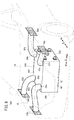
図8は、本発明の第2の実施形態に係る燃料電池車両100の前方部分の概略斜視説明図である。なお、第1の実施形態に係る燃料電池車両10と同一の構成要素には、同一の参照符号を付して、その詳細な説明は省略する。
FIG. 8 is a schematic perspective view of a front portion of a
燃料電池車両100は、燃料電池スタック12が収容されたスタックケース102を備える。スタックケース102は、アッパーパネル104を備え、前記アッパーパネル104は、前記スタックケース102の上面部を構成する。
The
アッパーパネル104には、一方の対角位置にスタックケース102内を外部に連通する開口部80a、80bが形成され、他方の対角位置に前記スタックケース102内を外部に連通する開口部80c、80dが形成される。開口部80a、80cは、スタックケース102の前方側両側部に設けられ、燃料ガス入口連通孔42aの鉛直方向上方に配置される。開口部80b、80dは、スタックケース102の後方側両側部に設けられる。
The
開口部80c、80dには、排気ダクト(ダクト部材)82c、82dの一端部が接続される。排気ダクト82cは、スタックケース102の上方に突出した後、燃料電池車両100の車幅方向他方(矢印BL方向)から前方側に延在し、車両側部の前方車両排気口84cに接続される。前方車両排気口84cは、フロントルーム18の外部に連通するとともに、スタックケース102の開口部80cよりも上方に離間する。
One ends of exhaust ducts (duct members) 82c and 82d are connected to the
排気ダクト82dは、スタックケース102の上方に突出した後、燃料電池車両100の車幅方向一方(矢印BR方向)から後方側に延在し、車両側部の後方車両排気口84dに接続される。後方車両排気口84dは、フロントルーム18の外部に連通するとともに、スタックケース102の開口部80dよりも上方に離間する。
After the
このように構成される第2の実施形態では、スタックケース102の上面を構成するアッパーパネル104には、2つの対角位置に対応して該スタックケース102内を外部に連通する4個の開口部80a〜80dが形成されている。そして、開口部80a〜80dには、排気ダクト82a〜82dの一端が接続されるとともに、前記排気ダクト82a〜82dの他端は、外部に開放されている。
In the second embodiment configured as described above, the
このため、燃料電池車両100が前後方向又は左右方向に傾斜しても、少なくとも開口部80a〜80dのいずれから燃料ガスを排出させることができる。従って、簡単な構成で、スタックケース102内に漏出した燃料ガスを、容易且つ確実に排出させることが可能になる等、上記の第1の実施形態と同様の効果が得られる。
For this reason, even if the
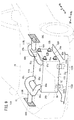
図9は、本発明の第3の実施形態に係る燃料電池車両110の前方部分の概略斜視説明図である。なお、第1及び第2の実施形態に係る燃料電池車両10、100と同一の構成要素には、同一の参照符号を付して、その詳細な説明は省略する。
FIG. 9 is a schematic perspective view of a front portion of a
燃料電池車両110は、燃料電池スタック12が収容されたスタックケース112を備える。図9〜図11に示すように、スタックケース112は、アッパーパネル114及びローワーパネル116を備える。アッパーパネル114は、スタックケース112の上面部を構成する一方、ローワーパネル116は、前記スタックケース112の下面部を構成する。
図9に示すように、アッパーパネル114には、排気ダクト82a〜82dの一端部が接続される。排気ダクト82aの他端部と排気ダクト82dの他端部とは、合流して右側排気ダクト118Rに接続されるとともに、前記右側排気ダクト118Rは、車両排気口84Rに接続される。排気ダクト82bの他端部と排気ダクト82cの他端部とは、合流して左側排気ダクト118Lに接続されるとともに、前記左側排気ダクト118Lは、車両排気口84Lに接続される。
As shown in FIG. 9, one end of
図10及び図11に示すように、ローワーパネル116には、車両前方側に2個(3個以上でもよい)の吸気用開口部118a、118bが形成される。吸気用開口部118a、118bは、スタックケース112内に開放されるとともに、タイロッド30(又は締結バー)の直下から前方又は後方にずれた位置に設けられる。第1エンドプレート26a側、すなわち、燃料ガス供給マニホールド62a及び燃料ガス排出マニホールド62b側に形成された吸気用開口部118bは、第2エンドプレート26b側に形成された吸気用開口部118aよりも大径に設定される。燃料ガスの漏出が、比較的多くなり易いからである。
As shown in FIGS. 10 and 11, the
吸気用開口部118a、118bには、ゴムホース120a、120bの一端部が接続されるとともに、前記ゴムホース120a、120bの他端部は、ジョイント122a、122bに接続される。図9に示すように、ジョイント122a、122bは、車体側アンダーカバー124に接続され、外部に開放される。なお、吸気用開口部118a、118bは、フロントルーム18内に、直接、開放されてもよい。
One end portions of the
このように構成される第3の実施形態では、図12に示すように、外部空気は、ゴムホース120a、120bを通って吸気用開口部118a、118bからスタックケース112内に導入されている。外部空気は、スタックケース112内を下方から上方に流通した後、開口部80a〜80dに接続された排気ダクト82a〜82dから外部に開放されている。
In the third embodiment configured as described above, as shown in FIG. 12, external air is introduced into the
その際、スタックケース112内に漏出した燃料ガスは、外部空気の流れに沿って一層容易且つ確実に外部に排出されることが可能になる。しかも、吸気用開口部118a、118bは、ローワーパネル116の車両前方側に位置して形成されている。このため、燃料電池車両110の走行中、前方から後方に流れる外部空気は、スタックケース112内を良好に流通することができ、燃料ガスの排出性が有効に向上する他、上記の第1及び第2の実施形態と同様の効果が得られる。
At that time, the fuel gas leaked into the
なお、第1〜第3の実施形態では、第1エンドプレート26a及び第2エンドプレート26bは、スタックケース14の構成部材として用いているが、これに限定されるものではなく、独立した直方体のケースの中に燃料電池スタック12を収容してもよい。
In the first to third embodiments, the
10、100、110…燃料電池車両 12…燃料電池スタック
14、102、112…スタックケース 18…フロントルーム
20…燃料電池 26a、26b…エンドプレート
32…電解質膜・電極構造体 34、36…セパレータ
38a…酸化剤ガス入口連通孔 38b…酸化剤ガス出口連通孔
40a…冷却媒体入口連通孔 40b…冷却媒体出口連通孔
42a…燃料ガス入口連通孔 42b…燃料ガス出口連通孔
44…酸化剤ガス流路 46…燃料ガス流路
48…冷却媒体流路 54…固体高分子電解質膜
56…カソード電極 58…アノード電極
66…前方サイドパネル 68…後方サイドパネル
70、104、114…アッパーパネル 72、116…ローワーパネル
80a〜80d…開口部 82a〜82d…排気ダクト
84a、84c…前方車両排気口 84b、84d…後方車両排気口
118a、118b…吸気用開口部 120a、120b…ゴムホース
122a、122b…ジョイント 124…車体用アンダーカバー
DESCRIPTION OF
Claims (8)
前記スタックケースの上面部には、少なくとも一方の対角位置に該スタックケース内を外部に連通する一対の開口部が形成され、
一方の前記開口部は前記フロントルームの前方側で車幅方向の一端側に設けられ、他方の前記開口部は前記フロントルームの後方側で車幅方向の他端側に設けられ、
前記フロントルームの車幅方向両端部には、該フロントルームの外部に連通し、且つ前記開口部よりも上方に位置して右側排出口及び左側排出口が設けられ、
車幅方向右側に設けられた前記開口部と前記右側排出口とに接続された右側ダクト部材と、
車幅方向左側に設けられた前記開口部と前記左側排出口とに接続された左側ダクト部材と、を備え、
前記開口部は前記一方の対角位置のみに設けられることを特徴とする燃料電池車両。 A fuel cell stack having a fuel gas communication hole in which a plurality of fuel cells that generate electric power by an electrochemical reaction between a fuel gas and an oxidant gas are stacked, and through which the fuel gas flows in the stacking direction of the fuel cells, has a rectangular shape in plan view The fuel cell vehicle is housed in a stack case, and the stack case is mounted in a front room formed in front of the dashboard.
In the upper surface portion of the stack case, a pair of openings communicating the inside of the stack case to the outside is formed at at least one diagonal position,
One opening is provided on one end side in the vehicle width direction on the front side of the front room, and the other opening is provided on the other end side in the vehicle width direction on the rear side of the front room,
At both ends in the vehicle width direction of the front room, a right discharge port and a left discharge port are provided in communication with the outside of the front room and located above the opening,
A right duct member connected to the opening and the right discharge port provided on the right side in the vehicle width direction;
A left duct member connected to the opening provided on the left side in the vehicle width direction and the left exhaust port;
The fuel cell vehicle according to claim 1, wherein the opening is provided at only one diagonal position.
前記スタックケースの上面部には、少なくとも一方の対角位置に該スタックケース内を外部に連通する一対の開口部が形成され、
一方の前記開口部は前記フロントルームの前方側で車幅方向の一端側に設けられ、他方の前記開口部は前記フロントルームの後方側で車幅方向の他端側に設けられ、
前記フロントルームの車幅方向両端部には、該フロントルームの外部に連通し、且つ前記開口部よりも上方に位置して右側排出口及び左側排出口が設けられ、
車幅方向右側に設けられた前記開口部と前記右側排出口とに接続された右側ダクト部材と、
車幅方向左側に設けられた前記開口部と前記左側排出口とに接続された左側ダクト部材と、を備え、
前記スタックケースの上面部の4つの角部のみにはそれぞれ前記開口部が設けられ、
前記フロントルームの車幅方向両端部には、車両前後方向に並んだ2つのみの前記右側排出口と車両前後方向に並んだ2つのみの左側排出口とが設けられるとともに、
車幅方向右側の2つのみの前記開口部と2つのみの前記右側排出口とにそれぞれ接続され、前記フロントルーム内で車幅方向に延在した2つのみの前記右側ダクト部材と、
車幅方向左側の2つのみの前記開口部と2つのみの前記左側排出口とにそれぞれ接続され、前記フロントルーム内で車幅方向に延在した2つのみの前記左側ダクト部材と、を備えることを特徴とする燃料電池車両。 A fuel cell stack having a fuel gas communication hole in which a plurality of fuel cells that generate electric power by an electrochemical reaction between a fuel gas and an oxidant gas are stacked, and through which the fuel gas flows in the stacking direction of the fuel cells, has a rectangular shape in plan view The fuel cell vehicle is housed in a stack case, and the stack case is mounted in a front room formed in front of the dashboard.
In the upper surface portion of the stack case, a pair of openings communicating the inside of the stack case to the outside is formed at at least one diagonal position,
One opening is provided on one end side in the vehicle width direction on the front side of the front room, and the other opening is provided on the other end side in the vehicle width direction on the rear side of the front room,
At both ends in the vehicle width direction of the front room, a right discharge port and a left discharge port are provided in communication with the outside of the front room and located above the opening,
A right duct member connected to the opening and the right discharge port provided on the right side in the vehicle width direction;
A left duct member connected to the opening provided on the left side in the vehicle width direction and the left exhaust port;
The openings are provided at only four corners of the top surface of the stack case,
Wherein the vehicle widthwise ends of the front room, with the only two arranged in the longitudinal direction of the vehicle right outlet and the vehicle longitudinal aligned in the direction the two only the left outlet and is provided,
Only the two said openings of only two right in the vehicle width direction which is connected respectively to the right outlet and the right duct member only two extending in the vehicle width direction in the front room,
Only the two said openings of the two only the left side in the vehicle width direction said are respectively connected to the left outlet, and a the left side duct member only two extending in the vehicle width direction in the front room A fuel cell vehicle comprising:
前記スタックケースの上面部には、少なくとも一方の対角位置に該スタックケース内を外部に連通する一対の開口部が形成され、
一方の前記開口部は前記フロントルームの前方側で車幅方向の一端側に設けられ、他方の前記開口部は前記フロントルームの後方側で車幅方向の他端側に設けられ、
前記フロントルームの車幅方向両端部には、該フロントルームの外部に連通し、且つ前記開口部よりも上方に位置して右側排出口及び左側排出口が設けられ、
車幅方向右側に設けられた前記開口部と前記右側排出口とに接続された右側ダクト部材と、
車幅方向左側に設けられた前記開口部と前記左側排出口とに接続された左側ダクト部材と、を備え、
前記スタックケースの上面部の4つの角部のみにはそれぞれ前記開口部が設けられ、
1つのみ設けられた前記右側ダクト部材は、車幅方向右側に2つのみ設けられた前記開口部に接続されるとともに中間部で合流して、前記フロントルームの車幅方向右側に1つのみ設けられた前記右側排出口に接続され、
1つのみ設けられた前記左側ダクト部材は、車幅方向左側に2つのみ設けられた前記開口部に接続されるとともに中間部で合流して、前記フロントルームの車幅方向左側に1つのみ設けられた前記左側排出口に接続されることを特徴とする燃料電池車両。 A fuel cell stack having a fuel gas communication hole in which a plurality of fuel cells that generate electric power by an electrochemical reaction between a fuel gas and an oxidant gas are stacked, and through which the fuel gas flows in the stacking direction of the fuel cells, has a rectangular shape in plan view The fuel cell vehicle is housed in a stack case, and the stack case is mounted in a front room formed in front of the dashboard.
In the upper surface portion of the stack case, a pair of openings communicating the inside of the stack case to the outside is formed at at least one diagonal position,
One opening is provided on one end side in the vehicle width direction on the front side of the front room, and the other opening is provided on the other end side in the vehicle width direction on the rear side of the front room,
At both ends in the vehicle width direction of the front room, a right discharge port and a left discharge port are provided in communication with the outside of the front room and located above the opening,
A right duct member connected to the opening and the right discharge port provided on the right side in the vehicle width direction;
A left duct member connected to the opening provided on the left side in the vehicle width direction and the left exhaust port;
The openings are provided at only four corners of the top surface of the stack case,
Only one provided with the right duct member, only one with joins in the middle section, to the right in the vehicle width direction of the front room is connected to the opening provided only two to the right in the vehicle width direction Connected to the provided right side outlet,
Only one provided with the left duct member, only one with joins in the middle portion, to the left in the vehicle width direction of the front room is connected to the opening provided only two to the left in the vehicle width direction A fuel cell vehicle connected to the provided left side exhaust port.
前記開口部は、前記燃料ガス連通孔の鉛直方向上方に配置されることを特徴とする燃料電池車両。 The fuel cell vehicle according to any one of claims 1 to 3 .
The fuel cell vehicle according to claim 1, wherein the opening is disposed vertically above the fuel gas communication hole.
Priority Applications (2)
| Application Number | Priority Date | Filing Date | Title |
|---|---|---|---|
| JP2015025256A JP6553371B2 (en) | 2014-03-20 | 2015-02-12 | Fuel cell vehicle |
| US14/661,197 US20150270562A1 (en) | 2014-03-20 | 2015-03-18 | Fuel cell vehicle |
Applications Claiming Priority (3)
| Application Number | Priority Date | Filing Date | Title |
|---|---|---|---|
| JP2014057384 | 2014-03-20 | ||
| JP2014057384 | 2014-03-20 | ||
| JP2015025256A JP6553371B2 (en) | 2014-03-20 | 2015-02-12 | Fuel cell vehicle |
Publications (3)
| Publication Number | Publication Date |
|---|---|
| JP2015193370A JP2015193370A (en) | 2015-11-05 |
| JP2015193370A5 JP2015193370A5 (en) | 2018-02-15 |
| JP6553371B2 true JP6553371B2 (en) | 2019-07-31 |
Family
ID=54142946
Family Applications (1)
| Application Number | Title | Priority Date | Filing Date |
|---|---|---|---|
| JP2015025256A Active JP6553371B2 (en) | 2014-03-20 | 2015-02-12 | Fuel cell vehicle |
Country Status (2)
| Country | Link |
|---|---|
| US (1) | US20150270562A1 (en) |
| JP (1) | JP6553371B2 (en) |
Families Citing this family (18)
| Publication number | Priority date | Publication date | Assignee | Title |
|---|---|---|---|---|
| US10060577B2 (en) * | 2013-10-28 | 2018-08-28 | Alternative Fuel Containers, Llc | Fuel gas storage tank with supporting filter tube(s) |
| JP6104864B2 (en) * | 2014-09-02 | 2017-03-29 | 本田技研工業株式会社 | Fuel cell stack and fuel cell vehicle |
| KR101734622B1 (en) * | 2014-11-21 | 2017-05-11 | 현대자동차주식회사 | Combination structure of fuel cell stack |
| JP6144303B2 (en) | 2015-08-27 | 2017-06-07 | 本田技研工業株式会社 | Fuel cell vehicle |
| JP6496233B2 (en) | 2015-10-21 | 2019-04-03 | 本田技研工業株式会社 | Fuel cell vehicle |
| JP6709058B2 (en) * | 2016-01-29 | 2020-06-10 | 本田技研工業株式会社 | Automotive fuel cell stack |
| JP6630185B2 (en) * | 2016-02-24 | 2020-01-15 | 本田技研工業株式会社 | Automotive fuel cell stack |
| JP6674367B2 (en) | 2016-11-17 | 2020-04-01 | 本田技研工業株式会社 | Automotive fuel cell stack |
| KR20180096986A (en) * | 2017-02-22 | 2018-08-30 | 말레 인터내셔널 게엠베하 | Fuel cell stack |
| JP6674403B2 (en) * | 2017-03-13 | 2020-04-01 | 本田技研工業株式会社 | Vehicle with fuel cell |
| JP6743769B2 (en) * | 2017-06-16 | 2020-08-19 | トヨタ自動車株式会社 | Fuel cell vehicle |
| JP6674485B2 (en) | 2018-01-25 | 2020-04-01 | 本田技研工業株式会社 | Exhaust device |
| JP6681929B2 (en) * | 2018-02-14 | 2020-04-15 | 本田技研工業株式会社 | Fuel cell system |
| JP7157538B2 (en) * | 2018-03-26 | 2022-10-20 | 本田技研工業株式会社 | fuel cell vehicle |
| CN110323472B (en) | 2018-03-30 | 2023-01-17 | 本田技研工业株式会社 | Fuel cell vehicle and fuel gas detection device for fuel cell |
| JP6979006B2 (en) * | 2018-12-11 | 2021-12-08 | 本田技研工業株式会社 | Fuel cell system |
| JP7103984B2 (en) | 2019-03-18 | 2022-07-20 | 本田技研工業株式会社 | Fuel cell stack |
| JP7165710B2 (en) * | 2020-10-30 | 2022-11-04 | 本田技研工業株式会社 | fuel cell vehicle |
Family Cites Families (13)
| Publication number | Priority date | Publication date | Assignee | Title |
|---|---|---|---|---|
| US5573867A (en) * | 1996-01-31 | 1996-11-12 | Westinghouse Electric Corporation | Purge gas protected transportable pressurized fuel cell modules and their operation in a power plant |
| JP2000225853A (en) * | 1999-02-09 | 2000-08-15 | Nissan Motor Co Ltd | Gas exhaust construction of on-vehicle fuel-cell |
| JP3791383B2 (en) * | 2001-10-10 | 2006-06-28 | 日産自動車株式会社 | Fuel tank mounting structure for fuel cell vehicles |
| DE10150385B4 (en) * | 2001-10-11 | 2005-12-08 | Ballard Power Systems Ag | The fuel cell system |
| JP2003173790A (en) * | 2001-12-06 | 2003-06-20 | Honda Motor Co Ltd | Fuel battery system for car |
| JP2004134181A (en) * | 2002-10-09 | 2004-04-30 | Nissan Motor Co Ltd | Fuel cell container structure |
| US20050095485A1 (en) * | 2003-10-31 | 2005-05-05 | 3M Innovative Properties Company | Fuel cell end plate assembly |
| JP2006004825A (en) * | 2004-06-18 | 2006-01-05 | Nissan Motor Co Ltd | Case structure of fuel cell |
| JP4820068B2 (en) * | 2004-08-02 | 2011-11-24 | 本田技研工業株式会社 | Fuel cell stack |
| JP4682564B2 (en) * | 2004-09-01 | 2011-05-11 | トヨタ自動車株式会社 | Gas detection system and gas detection method |
| KR20070117647A (en) * | 2005-04-14 | 2007-12-12 | 도요다 지도샤 가부시끼가이샤 | Arranging facility, parking facility, handling facility, and ventilation device |
| WO2007046490A1 (en) * | 2005-10-20 | 2007-04-26 | Toyota Jidosha Kabushiki Kaisha | Fuel cell stack case |
| JP6144303B2 (en) * | 2015-08-27 | 2017-06-07 | 本田技研工業株式会社 | Fuel cell vehicle |
-
2015
- 2015-02-12 JP JP2015025256A patent/JP6553371B2/en active Active
- 2015-03-18 US US14/661,197 patent/US20150270562A1/en not_active Abandoned
Also Published As
| Publication number | Publication date |
|---|---|
| US20150270562A1 (en) | 2015-09-24 |
| JP2015193370A (en) | 2015-11-05 |
Similar Documents
| Publication | Publication Date | Title |
|---|---|---|
| JP6553371B2 (en) | Fuel cell vehicle | |
| JP6144303B2 (en) | Fuel cell vehicle | |
| US9905878B2 (en) | Fuel cell stack and fuel cell vehicle | |
| US10879543B2 (en) | Fuel cell vehicle | |
| JP6709058B2 (en) | Automotive fuel cell stack | |
| JPWO2013111669A1 (en) | Fuel cell vehicle | |
| CN107069067B (en) | Fuel cell stack | |
| JP2017162560A (en) | On-vehicle mount structure of fuel cell stack | |
| US10322647B2 (en) | Fuel cell-equipped vehicle | |
| JP7103984B2 (en) | Fuel cell stack | |
| CN111313062B (en) | Fuel cell system | |
| JP6630185B2 (en) | Automotive fuel cell stack | |
| JP5207834B2 (en) | Automotive fuel cell stack | |
| JP6986049B2 (en) | Fuel cell system | |
| JP6681929B2 (en) | Fuel cell system | |
| JP2015182719A (en) | fuel cell vehicle | |
| JP2009277425A (en) | Fuel cell stack | |
| JP2014235947A (en) | Mounting structure for fuel cell stack | |
| JP2010125962A (en) | On-vehicle fuel cell system |
Legal Events
| Date | Code | Title | Description |
|---|---|---|---|
| A621 | Written request for application examination |
Free format text: JAPANESE INTERMEDIATE CODE: A621 Effective date: 20171129 |
|
| A521 | Written amendment |
Free format text: JAPANESE INTERMEDIATE CODE: A523 Effective date: 20180105 |
|
| A131 | Notification of reasons for refusal |
Free format text: JAPANESE INTERMEDIATE CODE: A131 Effective date: 20180911 |
|
| A977 | Report on retrieval |
Free format text: JAPANESE INTERMEDIATE CODE: A971007 Effective date: 20180913 |
|
| A521 | Written amendment |
Free format text: JAPANESE INTERMEDIATE CODE: A523 Effective date: 20181109 |
|
| A131 | Notification of reasons for refusal |
Free format text: JAPANESE INTERMEDIATE CODE: A131 Effective date: 20181127 |
|
| A521 | Written amendment |
Free format text: JAPANESE INTERMEDIATE CODE: A523 Effective date: 20190125 |
|
| TRDD | Decision of grant or rejection written | ||
| A01 | Written decision to grant a patent or to grant a registration (utility model) |
Free format text: JAPANESE INTERMEDIATE CODE: A01 Effective date: 20190625 |
|
| A61 | First payment of annual fees (during grant procedure) |
Free format text: JAPANESE INTERMEDIATE CODE: A61 Effective date: 20190704 |
|
| R150 | Certificate of patent or registration of utility model |
Ref document number: 6553371 Country of ref document: JP Free format text: JAPANESE INTERMEDIATE CODE: R150 |