JP6553045B2 - Display device especially for motor vehicles - Google Patents
Display device especially for motor vehicles Download PDFInfo
- Publication number
- JP6553045B2 JP6553045B2 JP2016541124A JP2016541124A JP6553045B2 JP 6553045 B2 JP6553045 B2 JP 6553045B2 JP 2016541124 A JP2016541124 A JP 2016541124A JP 2016541124 A JP2016541124 A JP 2016541124A JP 6553045 B2 JP6553045 B2 JP 6553045B2
- Authority
- JP
- Japan
- Prior art keywords
- display screen
- opaque mask
- outer frame
- front surface
- touch panel
- Prior art date
- Legal status (The legal status is an assumption and is not a legal conclusion. Google has not performed a legal analysis and makes no representation as to the accuracy of the status listed.)
- Active
Links
- 238000007650 screen-printing Methods 0.000 claims description 10
- 239000011521 glass Substances 0.000 claims description 5
- 230000001419 dependent effect Effects 0.000 claims description 2
- 239000002184 metal Substances 0.000 description 6
- 239000000463 material Substances 0.000 description 3
- 230000000007 visual effect Effects 0.000 description 3
- 238000005034 decoration Methods 0.000 description 2
- 239000010410 layer Substances 0.000 description 2
- 239000000853 adhesive Substances 0.000 description 1
- 238000004026 adhesive bonding Methods 0.000 description 1
- 230000001070 adhesive effect Effects 0.000 description 1
- 239000012790 adhesive layer Substances 0.000 description 1
- 239000003086 colorant Substances 0.000 description 1
- 230000008878 coupling Effects 0.000 description 1
- 238000010168 coupling process Methods 0.000 description 1
- 238000005859 coupling reaction Methods 0.000 description 1
- 239000000428 dust Substances 0.000 description 1
- 238000009429 electrical wiring Methods 0.000 description 1
- 239000006260 foam Substances 0.000 description 1
- 238000004519 manufacturing process Methods 0.000 description 1
- 238000000034 method Methods 0.000 description 1
- 230000003071 parasitic effect Effects 0.000 description 1
- 238000006748 scratching Methods 0.000 description 1
- 230000002393 scratching effect Effects 0.000 description 1
Images
Classifications
-
- B—PERFORMING OPERATIONS; TRANSPORTING
- B60—VEHICLES IN GENERAL
- B60K—ARRANGEMENT OR MOUNTING OF PROPULSION UNITS OR OF TRANSMISSIONS IN VEHICLES; ARRANGEMENT OR MOUNTING OF PLURAL DIVERSE PRIME-MOVERS IN VEHICLES; AUXILIARY DRIVES FOR VEHICLES; INSTRUMENTATION OR DASHBOARDS FOR VEHICLES; ARRANGEMENTS IN CONNECTION WITH COOLING, AIR INTAKE, GAS EXHAUST OR FUEL SUPPLY OF PROPULSION UNITS IN VEHICLES
- B60K35/00—Arrangement of adaptations of instruments
-
- B60K35/10—
-
- G—PHYSICS
- G06—COMPUTING; CALCULATING OR COUNTING
- G06F—ELECTRIC DIGITAL DATA PROCESSING
- G06F3/00—Input arrangements for transferring data to be processed into a form capable of being handled by the computer; Output arrangements for transferring data from processing unit to output unit, e.g. interface arrangements
- G06F3/01—Input arrangements or combined input and output arrangements for interaction between user and computer
- G06F3/03—Arrangements for converting the position or the displacement of a member into a coded form
- G06F3/041—Digitisers, e.g. for touch screens or touch pads, characterised by the transducing means
- G06F3/0412—Digitisers structurally integrated in a display
-
- G—PHYSICS
- G06—COMPUTING; CALCULATING OR COUNTING
- G06F—ELECTRIC DIGITAL DATA PROCESSING
- G06F3/00—Input arrangements for transferring data to be processed into a form capable of being handled by the computer; Output arrangements for transferring data from processing unit to output unit, e.g. interface arrangements
- G06F3/01—Input arrangements or combined input and output arrangements for interaction between user and computer
- G06F3/03—Arrangements for converting the position or the displacement of a member into a coded form
- G06F3/041—Digitisers, e.g. for touch screens or touch pads, characterised by the transducing means
- G06F3/045—Digitisers, e.g. for touch screens or touch pads, characterised by the transducing means using resistive elements, e.g. a single continuous surface or two parallel surfaces put in contact
-
- B60K2360/1438—
-
- B60K2360/20—
-
- B60K2360/688—
-
- B60K35/60—
-
- G—PHYSICS
- G01—MEASURING; TESTING
- G01C—MEASURING DISTANCES, LEVELS OR BEARINGS; SURVEYING; NAVIGATION; GYROSCOPIC INSTRUMENTS; PHOTOGRAMMETRY OR VIDEOGRAMMETRY
- G01C21/00—Navigation; Navigational instruments not provided for in groups G01C1/00 - G01C19/00
- G01C21/26—Navigation; Navigational instruments not provided for in groups G01C1/00 - G01C19/00 specially adapted for navigation in a road network
- G01C21/34—Route searching; Route guidance
- G01C21/36—Input/output arrangements for on-board computers
- G01C21/3667—Display of a road map
-
- G—PHYSICS
- G06—COMPUTING; CALCULATING OR COUNTING
- G06F—ELECTRIC DIGITAL DATA PROCESSING
- G06F3/00—Input arrangements for transferring data to be processed into a form capable of being handled by the computer; Output arrangements for transferring data from processing unit to output unit, e.g. interface arrangements
- G06F3/01—Input arrangements or combined input and output arrangements for interaction between user and computer
- G06F3/03—Arrangements for converting the position or the displacement of a member into a coded form
- G06F3/041—Digitisers, e.g. for touch screens or touch pads, characterised by the transducing means
- G06F3/044—Digitisers, e.g. for touch screens or touch pads, characterised by the transducing means by capacitive means
Description
本発明は、特に自動車やトラックなどの自動車両用の表示装置に関する。とりわけ本発明は、自動車のナビゲーション・システムやオンボード・コンピュータのための表示装置に関する。本発明はまた、本発明による表示装置を備えた自動車両のダッシュボードにも関する。 The present invention relates to a display device for an automobile such as an automobile or a truck. More particularly, the present invention relates to a display device for an automobile navigation system or on-board computer. The invention also relates to a dashboard of a motor vehicle equipped with a display device according to the invention.
自動車両には、タッチパネル付の表示装置を備えたヒューマン・マシン・インターフェイス類がますます備え付けられている。このタイプの装置は、自動車両における諸機能が制御されること、および使用者に役立つ情報が表示されることを可能とする。 Motor vehicles are increasingly equipped with human-machine interfaces with a display with touch panel. Devices of this type allow the functions in the motor vehicle to be controlled and information useful to the user to be displayed.
このタイプの表示装置は、少なくとも1つの表示スクリーンと、タッチパネルとを備えている。表示スクリーンは一般的に、ケーシングに固定されている。 This type of display device includes at least one display screen and a touch panel. The display screen is generally fixed to the casing.
表示スクリーンは典型的には、電子素子類によってアドレスされる表示領域を備えている。電子素子類は、表示スクリーンの外側部分に配置され、一般的には、組立体を一緒に保持する金属枠によって覆い隠される。これらの「技術的部分」とも呼ばれる電子素子類は、電気配線部、半田付けされたケーブル、および/または電子回路を包含し得る。 A display screen typically comprises a display area addressed by electronic elements. The electronics are located in the outer part of the display screen and are generally obscured by a metal frame which holds the assembly together. These electronic components, also referred to as "technical parts", may include electrical wiring, soldered cables, and / or electronic circuitry.
従来の諸構成においては、金属枠の一部が、表示スクリーンの前面上に伸びている。表示装置の使用者に金属枠が見えてしまうのは、特に美観上の理由で望ましくない。 In conventional configurations, a part of the metal frame extends on the front surface of the display screen. It is not desirable for the user of the display device to see the metal frame especially for aesthetic reasons.
特定の表示装置は、外縁部に追加的な装飾枠を備えたケーシングを具備している。その装飾枠は、表示の外縁部を覆い、かくして金属枠や、表示装置の別の技術的要素を覆い隠すものである。 Certain display devices include a casing with an additional decorative frame at the outer edge. The decorative frame covers the outer edge of the display, thus hiding the metal frame and other technical elements of the display.
他の従来技術の表示装置は、金属枠を覆い隠す単一の(一般的には黒色の)不透明マスクを備えている。 Other prior art displays include a single (typically black) opaque mask that obscures the metal frame.
しかしながら、このタイプの追加的な装飾枠や単一のマスクは、表示スクリーンにおける前面の中央の方向へ相当の距離を伸び、画像の一部をも使用者から覆い隠してしまう。特に、これは表示装置の前面に対して斜めに位置する使用者たちに当て嵌まる。自動車両の状況においては、斜めの位置は、最もありがちな使用者の位置なのである。 However, this type of additional decorative frame or single mask extends a considerable distance in the direction towards the center of the front face of the display screen and may even obscure part of the image from the user. In particular, this applies to users who are located obliquely with respect to the front face of the display device. In the situation of motor vehicles, the diagonal position is the most likely user position.
本発明の目的は、表示スクリーンの全ての表示領域を使用者が見ることを可能としながら、表示スクリーンの技術的な諸要素および/または金属枠が覆われることを可能とする表示装置を提供することである。 The object of the present invention is to provide a display device which allows the technical elements of the display screen and / or the metal frame to be covered while allowing the user to see all the display area of the display screen. It is.
この目的のために本発明は、特に自動車両用の表示装置であって、
− 表示スクリーンと、
− 表示スクリーンの前方に配置されたタッチパネルと、
− 表示スクリーンにおける前面の一部の上に配置された外枠と、
− タッチパネルと外枠との間に配置されて、当該外枠を覆うように、表示スクリーンにおける前面の中央の方向へ外枠を越えて伸びる第1不透明マスクと、
− タッチパネルの前方に配置されて、第1マスクの前方に配置されたタッチパネルの前面の外側部分を覆う第2不透明マスクと、
を備え、
第1マスクは、スクリーンにおける前面の中央の方向へ第2マスクを越えて伸びている、表示装置に関するものである。
For this purpose, the invention is a display device, in particular for motor vehicles,
-Display screen,
-A touch panel arranged in front of the display screen;
-An outer frame arranged on a part of the front surface of the display screen;
A first opaque mask disposed between the touch panel and the outer frame and extending beyond the outer frame in a direction towards the center of the front face of the display screen so as to cover the outer frame;
A second opaque mask disposed in front of the touch panel and covering an outer portion of the front surface of the touch panel disposed in front of the first mask;
Equipped with
The first mask relates to a display which extends beyond the second mask in the direction towards the center of the front face of the screen.
互いに相対的にずらされた2つのマスクの使用によって、使用者が表示スクリーンの全ての表示領域を見ることができるようにしながら、外枠を覆うことが可能となることが有利である。単一のマスクで同様の覆い隠しを得るには、当該マスクがタッチパネルの前方に、即ち:本発明による第1マスクよりも外枠から遠く配置されねばならないであろうし、従って本発明による第1マスクよりもスクリーンにおける前面の中央の方向へ更に伸びることになるであろう。単一のマスクは従って、スクリーンの画像の一部を覆ってしまうのである。 Advantageously, the use of two masks which are offset relative to one another enables the covering of the outer frame, while allowing the user to see the whole display area of the display screen. In order to obtain a similar concealment with a single mask, the mask will have to be arranged in front of the touch panel, ie further from the outer frame than the first mask according to the invention, and thus the first according to the invention It will extend further in the direction of the front center of the screen than the mask. A single mask thus covers a portion of the screen image.
本発明による装置はまた、個別に、或いは技術的に可能な任意の組み合わせで考えられる、以下の特徴のうち1つないし複数を備えていてもよい:
− 表示スクリーンの前面、タッチパネルの前面、並びに第1および第2マスクは、実質的に平坦であって互いに平行であること;および/または、
− 当該表示装置の少なくとも1つの断面において、第1マスクにおける表示スクリーンの前面の中央に最も近い点と、第2マスクにおける表示スクリーンの前面の中央に最も近い点とを結ぶ直線が、第1マスクにおける表示スクリーンの前面の中央に最も近い点の所でのスクリーンの前面に対する法線と、10°以上55°以下の角度を成していること;および/または、
− 当該表示装置の少なくとも1つの断面において、第1マスクにおける表示スクリーンの前面の中央に最も近い点と、外枠における表示スクリーンの前面の中央に最も近い点とを結ぶ直線が、第1マスクにおける表示スクリーンの前面の中央に最も近い点の所でのスクリーンの前面に対する法線と、10°以上55°以下の角度を成していること;および/または、
− 当該表示装置は、表示スクリーンが固定されるケーシングを更に備えていること;および/または、
− 第2マスクは、ケーシングの少なくとも一部を覆うように配置されていること;および/または、
− タッチパネルは静電容量式または抵抗式であること、および/または、
− 当該表示装置は、第2マスクとタッチパネルの前面との上に配置された透明シートを更に備えていること;および/または、
− 不透明マスクは、スクリーン印刷によってガラス上に被着されていること;および/または、
− 第2不透明マスクは、スクリーン印刷によって透明シート上に被着されていること;および/または、
− 第1マスクは、スクリーン印刷によってタッチパネルの後面上に被着されていること。
The device according to the invention may also comprise one or more of the following features, considered individually or in any technically possible combination:
The front surface of the display screen, the front surface of the touch panel, and the first and second masks are substantially flat and parallel to each other; and / or
-A straight line connecting a point closest to the center of the front surface of the display screen in the first mask and a point closest to the center in the front surface of the display screen of the second mask in at least one cross section of the display device is the first mask An angle of 10 ° to 55 ° with the normal to the front of the screen at the point closest to the center of the front of the display screen;
-In at least one cross section of the display device, a straight line connecting a point closest to the center of the front surface of the display screen in the first mask and a point closest to the center in the front surface of the display screen in the outer frame corresponds to the first mask An angle of 10 ° to 55 ° with the normal to the front of the screen at the point closest to the center of the front of the display screen; and / or
-The display further comprises a casing to which the display screen is fixed; and / or
-The second mask is arranged to cover at least a part of the casing; and / or
The touch panel is capacitive or resistive and / or
-The display further comprises a transparent sheet disposed on the second mask and the front surface of the touch panel; and / or
-The opacity mask is deposited on the glass by screen printing; and / or
-The second opaque mask is deposited on the transparent sheet by screen printing; and / or
-The first mask is deposited on the back surface of the touch panel by screen printing.
本発明はまた、特に自動車両用の表示装置であって、
− 表示スクリーンと、
− 表示スクリーンの前方に配置されたタッチパネルと、
− 表示スクリーンにおける前面の一部の上に配置された外枠と、
− タッチパネルと外枠との間に配置されて、当該外枠を覆うように、表示スクリーンにおける前面の中央の方向へ外枠を越えて伸びる第1不透明マスクと、
を備え、第1不透明マスクは、スクリーン印刷によってタッチパネルの後面上に被着されている、表示装置にも関する。
The invention is also a display device, in particular for a motor vehicle,
-Display screen,
-A touch panel arranged in front of the display screen;
-An outer frame arranged on a part of the front surface of the display screen;
A first opaque mask disposed between the touch panel and the outer frame and extending beyond the outer frame in a direction towards the center of the front face of the display screen so as to cover the outer frame;
The first opaque mask also relates to a display device, which is deposited on the back surface of the touch panel by screen printing.
本発明による装置はまた、個別に、或いは技術的に可能な任意の組み合わせで考えられる、以下の特徴のうち1つないし複数を備えていてもよい:
− 当該装置は、タッチパネルの前方に配置されて、第1マスクの前方に配置されたタッチパネルの前面の外側部分を覆う第2不透明マスクを更に備え、第1および第2マスクは、スクリーンにおける前面の中央の方向へ外枠を越えて実質的に同様に伸びていること;および/または、
− 第1マスクは、スクリーンにおける前面の中央の方向へ第2マスクを越えて伸びていること;および/または、
− 表示スクリーンの前面、タッチパネルの前面、並びに第1および第2マスクは、実質的に平坦であって互いに平行であること;および/または、
− 当該表示装置の少なくとも1つの断面において、第1マスクにおける表示スクリーンの前面の中央に最も近い点と、第2マスクにおける表示スクリーンの前面の中央に最も近い点とを結ぶ直線が、第1マスクにおける表示スクリーンの前面の中央に最も近い点の所でのスクリーンの前面に対する法線と、10°以上55°以下の角度を成していること;および/または、
− 当該表示装置の少なくとも1つの断面において、第1マスクにおける表示スクリーンの前面の中央に最も近い点と、外枠における表示スクリーンの前面の中央に最も近い点とを結ぶ直線が、第1マスクにおける表示スクリーンの前面の中央に最も近い点の所でのスクリーンの前面に対する法線と、10°以上55°以下の角度を成していること;および/または、
− 当該表示装置は、表示スクリーンが固定されるケーシングを更に備えていること;および/または、
− 第2マスクは、ケーシングの少なくとも一部を覆うように配置されていること;および/または、
− タッチパネルは静電容量式または抵抗式であること。
The device according to the invention may also comprise one or more of the following features, considered individually or in any technically possible combination:
The apparatus further comprises a second opaque mask disposed in front of the touch panel and covering an outer portion of the front surface of the touch panel disposed in front of the first mask, wherein the first and second masks Extend substantially similarly across the shell in the central direction; and / or
The first mask extends beyond the second mask in the direction towards the center of the front face of the screen; and / or
The front surface of the display screen, the front surface of the touch panel, and the first and second masks are substantially flat and parallel to each other; and / or
-A straight line connecting a point closest to the center of the front surface of the display screen in the first mask and a point closest to the center in the front surface of the display screen of the second mask in at least one cross section of the display device is the first mask An angle of 10 ° to 55 ° with the normal to the front of the screen at the point closest to the center of the front of the display screen;
-In at least one cross section of the display device, a straight line connecting a point closest to the center of the front surface of the display screen in the first mask and a point closest to the center in the front surface of the display screen in the outer frame corresponds to the first mask An angle of 10 ° to 55 ° with the normal to the front of the screen at the point closest to the center of the front of the display screen; and / or
-The display further comprises a casing to which the display screen is fixed; and / or
-The second mask is arranged to cover at least a part of the casing; and / or
-The touch panel must be capacitive or resistive.
本発明はまた、本発明による表示装置を備えた自動車両のダッシュボードにも関する。 The invention also relates to a dashboard of a motor vehicle equipped with a display device according to the invention.
本発明は、その実施の(非限定的な例として与えられる)以下の説明を読み取ることで、また添付図面を考察することによって、より良好に理解されることとなる。 The invention will be better understood on reading the following description of its implementation (given as a non-limiting example) and on examining the attached drawings.
本発明の文脈では、表示装置のある要素の「前面」によって意味するものは、使用時において表示装置の最終使用者に最も近い当該要素の表面である。 In the context of the present invention, what is meant by the "front side" of an element of a display is the surface of the element closest to the end user of the display in use.
本発明の文脈では、使用時において第1の要素が第2の要素よりも表示装置の最終使用者に近いとき、第1の要素は第2の要素の「前方」に置かれている。 In the context of the present invention, when in use the first element is closer to the end user of the display than the second element, the first element is placed "forward" of the second element.
本発明の文脈では、「面の外側部分」によって意味するものは、この面の縁部に位置した部分、換言すれば、この面の中央の側に置かれた面の中央部分に対するものとしての、面の外周に最も近い部分である。 In the context of the present invention, what is meant by "outside part of a face" is that for the part located at the edge of this face, in other words for the central part of the face placed on the central side of this face. , Is the part closest to the outer periphery of the surface.
本発明の文脈では、「面の中央」によって意味するものは、当該面の外周の、内側に内接する円の中心、または周囲に外接する円の中心である。 In the context of the present invention, what is meant by "center of a face" is the center of the circle inscribed in the periphery of the face, or the center of the circle circumscribed to the periphery.
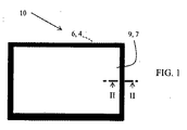
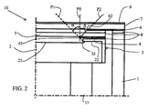
図2を参照すると、本発明による表示装置10は、ケーシング1と表示スクリーン2とを備えている。
Referring to FIG. 2, the
ケーシング1は、略平行六面体形状であって、各側壁と、後壁と、前壁とを有していることが好ましい。ケーシング1の前壁は、透明ないし半透明のシート7、例えばスモーク加工されたシートの形態をとり得る。この透明シート7は、それを通して使用者に表示スクリーン2の表示が見えるように設置されている。
The
透明シート7は多くの場合、ケーシング1の各側壁に対して、例えば接着剤8によって固定されている。特に、透明シート7は、ガラス、プラスチック、或いは当業者に知られた他のどのような同等の材料で出来ていてもよい。そのシートは、表示装置10の諸要素を保護するのに役立ち得る。それは例えば、ケーシングの中へ塵埃が入るのを防止するためである。シート7は、本発明による表示装置を補剛したり装飾したりする機能をも有している。シート7は、表示装置における目に見えて触れられる要素となっている。
In many cases, the transparent sheet 7 is fixed to each side wall of the
ケーシングの内部には、表示スクリーン2が固定されている。表示スクリーン2は、TFT、LCM、LCD、またはOLEDのスクリーンであってよい。 A display screen 2 is fixed inside the casing. The display screen 2 may be a TFT, LCM, LCD, or OLED screen.
表示スクリーン2の前面は、表示領域21と、外側部分22とを備えている。
The front surface of the display screen 2 includes a
表示スクリーン2は、その後面を介してケーシング1に固定されていることが好ましい。表示スクリーンはまた、(シート7に剛性がある場合には)接着性接合によってシート7の下に吊り下げられたり、バネや発泡体などの弾性要素の影響を受けてシートに押し付けられたりしていてもよい。
The display screen 2 is preferably fixed to the
表示スクリーン2の前面における外側部分22の一部の上に、外枠3が伸びている。
An
外枠3は、表示スクリーンの各側面のうち1つの上にも設置されていてよい。外枠3は、表示スクリーンの機能(例えばアドレッシング)を確保する技術的要素の組を覆っている。この(一般的にはベゼルと呼ばれる)外枠3ないし装飾枠は、スクリーンの外周上に設置されて、その各端面を保護する。
The
典型的には、外枠3は、薄さを保ちつつ、表示スクリーンの優れた機械的保護を可能とするため、またスクリーンの縁部上に配置された電子回路や配線部を静電気放電から保護するための材料で出来ている。ガラスの引っ掻き傷を防ぐため、外枠とスクリーンの表面との間にシールが配置されるのが一般的である。
Typically, the
表示装置10は、表示スクリーンの前方に配置されたタッチパネル5を更に備えている。タッチパネル5は、表示スクリーン2と透明シート7との間に配置されている。タッチパネル5は、表示スクリーンの表示領域21の全体に渡って広がっていることが好ましい。タッチパネルは、表示スクリーンに対して相対的に固定的に配置されていることが好ましい。タッチパネル5は、抵抗式や静電容量式のものであってよい。
The
透明シート7は、タッチパネル5の一面に渡って広がっている。 The transparent sheet 7 extends over one surface of the touch panel 5.
図2に示すように、本発明による表示装置10は、タッチパネル5と表示スクリーン2との間に配置された第1不透明マスク4を備えている。第1マスク4は、表示スクリーンの前面における外側部分の一部を覆うように配置されている。
As shown in FIG. 2, the
第1マスクは、表示スクリーンの前面の外側部分における、少なくとも外枠3の配置される部分を覆うように配置されていることが好ましい。
The first mask is preferably arranged to cover at least a portion of the outer surface of the front surface of the display screen where the
「(表)面の一部(分)を覆う」によって意味するものは、不透明マスクで当該部分を覆い隠すことによって、使用時に表示装置の最終使用者に当該部分が見えないようにする、という事である。 What is meant by “covering a part (minute) of the (front) surface” ”is that by covering the part with an opaque mask, the part is not visible to the end user of the display device in use It is a thing.
表示装置10はまた、タッチパネルの前方に配置されて、第1マスク4の前方に配置されたタッチパネルにおける前面の前方の外側部分を覆う第2不透明マスク6をも備えている。
The
第1マスク4は、スクリーンにおける前面の中央の方向へ第2マスク6を越えて伸びている。そのような構成によって、表示スクリーンの前面における表示部分の(とりわけ斜めから見たときの)最大限の視認性を使用者が有することを保証しつつ、表示スクリーンの外側区域の部分を覆うことが可能となって有利である。
The
実際には、本発明による装置の第1および第2マスクは、薄い不透明層である。 In practice, the first and second masks of the device according to the invention are thin opaque layers.
本発明の好適な一実施形態によれば、表示スクリーンの前面、タッチパネルの前面、並びに第1および第2マスクは、実質的に平坦であって互いに平行である。同様に、透明シートは、平坦であって、表示スクリーンの前面に対して実質的に平行であることが好ましい。 According to a preferred embodiment of the present invention, the front surface of the display screen, the front surface of the touch panel, and the first and second masks are substantially flat and parallel to one another. Similarly, the transparent sheet is preferably flat and substantially parallel to the front surface of the display screen.
図2に示すように、表示装置10の少なくとも1つの断面において、第1マスク4は、表示スクリーンにおける前面の中央の方向へ外枠3を越えて、第1の点42まで伸びている。
As shown in FIG. 2, in at least one cross section of the
特に、図1で分かり得るように、表示装置の少なくとも1つの断面において、第1マスクにおける表示スクリーンの前面の中央に最も近い点42と、第2マスクにおける表示スクリーンの前面の中央に最も近い点62との間の直線P2を定義することができる。 In particular, as can be seen in FIG. 1, the point 42 closest to the center of the front of the display screen in the first mask and the point closest to the center of the front of the display screen in the second mask in at least one cross section of the display A straight line P2 between 62 can be defined.
直線P2は、表示装置10に対して斜めに位置した使用者の入射視覚経路を表す。
The straight line P <b> 2 represents the incident visual path of the user positioned obliquely with respect to the
また、第1マスクにおける表示スクリーンの前面の中央に最も近い点42と、外枠における表示スクリーンの前面の中央に最も近い点32との間の直線P1も定義することができる。
A straight line P1 can also be defined between the point 42 closest to the center of the front surface of the display screen in the first mask and the
まさに上記のように、直線P1は、表示装置に対して斜めに位置した使用者の入射視覚経路を表す。 Just as described above, the straight line P1 represents the incident visual path of the user positioned obliquely with respect to the display device.
本発明の一実施形態によれば、表示装置は、直線P2と、第1マスクにおける表示スクリーンの前面の中央に最も近い点42の所でのスクリーンの前面に対する法線P0との間の角度βが、0°以上(例えば10°以上、例えば15°以上)55°以下(例えば45°以下)であるように構成される。 According to one embodiment of the present invention, the display device has an angle β between the straight line P2 and a normal P0 to the front of the screen at a point 42 closest to the center of the front of the display screen in the first mask. Is configured to be 0 ° or more (eg, 10 ° or more, eg, 15 ° or more) and 55 ° or less (eg, 45 ° or less).
同様に、本発明の別の実施形態によれば、表示装置は、直線P1と、第1マスクにおける表示スクリーンの前面の中央に最も近い点42の所でのスクリーンの前面に対する法線P0との間の角度αが、10°以上(例えば15°以上)55°以下(例えば45°以下)であるように構成される。 Similarly, according to another embodiment of the present invention, the display device comprises a straight line P1 and a normal P0 to the front of the screen at a point 42 closest to the center of the front of the display screen in the first mask. The angle α between them is configured to be 10 ° or more (for example, 15 ° or more) and 55 ° or less (for example, 45 ° or less).
それらのようなαおよびβの値は、斜めに位置した使用者が、概して光沢のある外枠3の縁部を知覚してしまうことを防止する。
The values of .alpha. And .beta. Such as these prevent obliquely positioned users from perceiving the edge of the generally
また、斜め方向の使用者は、表示領域21の縁部の最大限を知覚する。
Further, the user in the oblique direction perceives the maximum edge of the
一般的に外枠3の縁部32よりも画像の方が極めて僅か(1から2mm)だけ小さいという事実を利用して、点32が第1マスク4の位置の許容偏差を吸収するようにも定置されることとなる、即ち、第1マスク4が表示スクリーンにおける前面の中央の方向へ必要よりも少しだけ多く伸びるのが有利である。
By taking advantage of the fact that the image is generally only slightly smaller (1 to 2 mm) than the
第2マスクのようにタッチパネルの前方に配置された単一のマスクで同じ角度αを得るには、当該マスクは、スクリーンの中央の方向へ第1マスク4よりも長く伸びなくてはならず、かくして表示領域21の一部を覆ってしまうであろう、ということが明らかであることとなる。
In order to obtain the same angle α with a single mask placed in front of the touch panel, like the second mask, the mask must extend longer than the
かくして、第1マスク4は枠の最適な覆い隠しを可能とし、第2マスク6は悪くとも表示領域21の縁部の視認を許容する。特に、マスク4は、視野をできるだけ少ししか縮小させないよう、外枠3にできるだけ近く配置される。
Thus, the
図2に示すように、タッチパネルは、1つないし複数の接着剤層8によって、外枠に対して接着性接合され得る。同じことが、ケーシングに対して固定される透明シート7にも当て嵌まる。 As shown in FIG. 2, the touch panel may be adhesively bonded to the outer frame by one or more adhesive layers 8. The same applies to the transparent sheet 7 fixed to the casing.
透明シート7は、その透明シート7からの寄生反射を制限する偏光材9で被われていてもよい。 The transparent sheet 7 may be covered with a polarizing material 9 that restricts parasitic reflection from the transparent sheet 7.
表示スクリーン2は、この場合、連結要素11によってケーシングに固定され、好ましくはケーシングにネジ止め(図示せず)される。 The display screen 2 is in this case fixed to the casing by means of the coupling element 11 and is preferably screwed (not shown) to the casing.
第1および/または第2マスクは、不透明であり、また画像を枠内に収める縁を形成するために、装飾と調和したり対照をなしたりする灰色や黒色の単色ないし複数色のものであってよく、或いは、ぼかされていてもよい。 The first and / or second masks are opaque and are gray or black single color or multiple colors to match or contrast with the decoration to form an edge that fits the image within the frame Or it may be blurred.
本発明による装置の製造は、上述したように配置されるよう第1および第2マスクの位置が定められる段階を含んでいる。一実施形態によれば、それらのマスクはガラス上へのスクリーン印刷によって作られてよい。 The manufacture of the device according to the invention comprises the steps of positioning the first and second masks to be arranged as described above. According to one embodiment, the masks may be made by screen printing on glass.
このスクリーン印刷法によって、薄い層の形態をとるマスクを、透明シート7および/またはタッチパネル5上に、精確で、複写可能に、かつ低コストで作り出すことが可能となる。 This screen printing method makes it possible to produce a mask in the form of a thin layer on the transparent sheet 7 and / or the touch panel 5 accurately, reproducibly and at low cost.
もちろん本発明は、説明した各実施形態に限定されるものではなく、依然として特許請求の範囲の範囲内にありながら他の諸変形例へ拡張されるものである。 Of course, the present invention is not limited to the embodiments described, but extends to other variations while remaining within the scope of the claims.
本明細書において、用語「備えている/備えた/備え(comprising)」は他の諸要素を除外するものではなく、不定冠詞「ある(a)」や「1つの/一(one)」は複数を除外するものではない。様々な特徴が様々な従属請求項で一緒に引用されているという単純な事実は、これらの特徴の組み合わせを有利に用いることができない、ということを示すものではない。 As used herein, the term "comprising / comprising" does not exclude other elements, and the indefinite article "a" or "one" means "one" or "one". It does not exclude plural. The mere fact that various features are recited together in various dependent claims does not indicate that a combination of these features can not be used to advantage.
特許請求の範囲における如何なる参照符号も、本発明の範囲を制限するものとして解釈してはならない。 Any reference signs in the claims should not be construed as limiting the scope of the invention.
Claims (14)
− 表示領域(21)及び外側部分(22)を有する前面を有する表示スクリーン(2)と、
− 前記表示スクリーンの前方に配置されたタッチパネル(5)と、
− 前記表示スクリーン(2) とタッチパネル(5)との間に配置されて前記表示スクリーン(2)の周縁の全域を覆う外枠(3)であって、前記外枠(3)は側部及び横方向延伸部を有するL字形を有し、前記外枠(3)の前記側部が前記表示スクリーン(2)の側面に沿って延び、前記外枠(3)の前記横方向延伸部が前記表示スクリーン(2)の前記外側部分(22)の全域および前記表示スクリーン(2)の前記表示領域(21)の一部分を覆って延びている、前記外枠(3)と、
− 前記タッチパネル(5)と前記外枠(3)との間において前記外枠(3)の前方に配置された第1不透明マスク(4)であって、前記外枠(3)の前記横方向延伸部の全域を覆うとともに、前記外枠(3)の前記横方向延伸部を越えて前記表示スクリーンの表示領域(21)の一部分を覆うように延びて、前記外枠(3)を覆い隠す、前記第1不透明マスク(4)と、
− 前記第1不透明マスク(4)の前方であってかつ前記タッチパネル(5)の前方に配置された第2不透明マスク(6)であって、少なくとも前記タッチパネル(5)の縁から延びて前記タッチパネル(5)の前面の外側部分を覆い隠している、前記第2不透明マスク(6)と、
を備え、
前記第2不透明マスク(6)は、前記外枠(3)の横方向に延伸する表面の一部を覆うように延び、
前記第1不透明マスク(4)は、前記表示スクリーン(2)の前記前面の中央の方向へ前記第2不透明マスク(6)を越えて延びており、これにより、前記第1不透明マスク(4)における前記表示スクリーン(2)の前記前面の中央に最も近い点(42)と、前記第2不透明マスク(6)における前記表示スクリーン(2)の前記前面の中央に最も近い点(62)とを結ぶ直線(P2)が、前記第1不透明マスク(4)における前記表示スクリーンの前記前面の中央に最も近い点(42)の所での前記表示スクリーン(2)の前面に対する法線(P0)と、0°以上55°以下の角度(β)を成している、表示装置。 In particular a display device for motor vehicles,
A display screen (2) having a front face with a display area (21) and an outer part (22) ;
A touch panel (5) arranged in front of the display screen;
An outer frame (3) disposed between the display screen (2) and the touch panel (5) and covering the entire periphery of the display screen (2), wherein the outer frame (3) It has an L-shape having a laterally extending portion, and the side portion of the outer frame (3) extends along the side surface of the display screen (2), and the laterally extending portion of the outer frame (3) is The outer frame (3) extending over the entire outer portion (22) of the display screen (2) and a part of the display area (21) of the display screen (2) ;
- wherein a touch panel (5) and the outer frame (3) first opaque mask disposed in front of Oite the outer frame (3) between the (4), wherein the outer frame (3) Covering the entire region of the laterally extending portion and extending beyond the laterally extending portion of the outer frame (3) so as to cover a part of the display area (21) of the display screen, the outer frame (3) Covering the first opaque mask (4);
A second opaque mask (6) disposed in front of the first opaque mask (4) and in front of the touch panel (5), and extending from at least an edge of the touch panel (5); (5) hides have covering an outer portion of the front of, and the second opaque mask (6),
Equipped with
The second opaque mask (6) extends to cover a portion of the laterally extending surface of the outer frame (3);
The first opaque mask (4) extends beyond the second opaque mask (6) in the direction of the center of the front surface of the display screen (2) , whereby the first opaque mask (4). A point (42) that is closest to the center of the front surface of the display screen (2) and a point (62) that is closest to the center of the front surface of the display screen (2) in the second opaque mask (6). A connecting line (P2) is a normal line (P0) to the front surface of the display screen (2) at a point (42) closest to the center of the front surface of the display screen in the first opaque mask (4). A display device having an angle (β) of 0 ° to 55 ° .
− 表示領域(21)及び外側部分(22)を有する前面を有する表示スクリーン(2)と、
− 前記表示スクリーンの前方に配置されたタッチパネル(5)と、
− 前記表示スクリーン(2) とタッチパネル(5)との間に配置されて前記表示スクリーン(2)の周縁の全域を覆う外枠(3)であって、前記外枠(3)は側部及び横方向延伸部を有するL字形を有し、前記外枠(3)の前記側部が前記表示スクリーン(2)の側面に沿って延び、前記外枠(3)の前記横方向延伸部が前記表示スクリーン(2)の前記外側部分(22)の全域および前記表示スクリーン(2)の前記表示領域(21)の一部分を覆って延びている、前記外枠(3)と、
− 前記タッチパネル(5)と前記外枠(3)との間において前記外枠(3)の前方に配置された第1不透明マスク(4)であって、前記外枠(3)の前記横方向延伸部の全域を覆うとともに、前記外枠(3)の前記横方向延伸部を越えて前記表示スクリーンの表示領域(21)の一部分を覆うように延びて、前記外枠(3)を覆い隠す、前記第1不透明マスク(4)と、
前記第1不透明マスク(4)の前方であってかつ前記タッチパネル(5)の前方に配置された第2不透明マスク(6)であって、少なくとも前記タッチパネル(5)の縁から延びて前記タッチパネル(5)の前面の外側部分を覆い隠している、前記第2不透明マスク(6)と、
を備え、
前記第1不透明マスク(4)は、スクリーン印刷によって前記タッチパネル(5)の後面上に被着されており、
前記第1不透明マスク(4)は、前記表示スクリーン(2)の前記前面の中央の方向へ前記第2不透明マスク(6)を越えて延びており、これにより、前記第1不透明マスク(4)における前記表示スクリーン(2)の前記前面の中央に最も近い点(42)と、前記第2不透明マスク(6)における前記表示スクリーン(2)の前記前面の中央に最も近い点(62)とを結ぶ直線(P2)が、前記第1不透明マスク(4)における前記表示スクリーンの前記前面の中央に最も近い点(42)の所での前記表示スクリーン(2)の前面に対する法線(P0)と、0°以上55°以下の角度(β)を成している、表示装置。 In particular a display device for motor vehicles,
A display screen (2) having a front face with a display area (21) and an outer part (22) ;
A touch panel (5) arranged in front of the display screen;
An outer frame (3) disposed between the display screen (2) and the touch panel (5) and covering the entire periphery of the display screen (2), wherein the outer frame (3) It has an L-shape having a laterally extending portion, and the side portion of the outer frame (3) extends along the side surface of the display screen (2), and the laterally extending portion of the outer frame (3) is The outer frame (3) extending over the entire outer portion (22) of the display screen (2) and a part of the display area (21) of the display screen (2) ;
A first opaque mask (4) disposed in front of the outer frame (3) between the touch panel (5) and the outer frame (3), wherein the lateral direction of the outer frame (3); The entire extending portion is covered, and extends beyond the lateral extending portion of the outer frame (3) so as to cover a part of the display area (21) of the display screen, thereby covering the outer frame (3). the first opaque mask (4),
A second opaque mask (6) disposed in front of the first opaque mask (4) and in front of the touch panel (5), and extending from at least an edge of the touch panel (5) to the touch panel ( The second opaque mask (6) covering the outer part of the front surface of 5) ;
Equipped with
The first opaque mask (4) is deposited on the rear surface of the touch panel (5) by screen printing ;
The first opaque mask (4) extends beyond the second opaque mask (6) in the direction of the center of the front surface of the display screen (2) , whereby the first opaque mask (4). A point (42) closest to the center of the front surface of the display screen (2) and a point (62) closest to the center of the front surface of the display screen (2) in the second opaque mask (6) A connecting line (P2) is a normal line (P0) to the front surface of the display screen (2) at a point (42) closest to the center of the front surface of the display screen in the first opaque mask (4). A display device having an angle (β) of 0 ° to 55 ° .
Applications Claiming Priority (3)
| Application Number | Priority Date | Filing Date | Title |
|---|---|---|---|
| FR1303043A FR3015753B1 (en) | 2013-12-20 | 2013-12-20 | DISPLAY DEVICE, IN PARTICULAR FOR A MOTOR VEHICLE |
| FR1303043 | 2013-12-20 | ||
| PCT/FR2014/000294 WO2015092170A1 (en) | 2013-12-20 | 2014-12-18 | Display device intented notably for a motor vehicle |
Publications (2)
| Publication Number | Publication Date |
|---|---|
| JP2017503202A JP2017503202A (en) | 2017-01-26 |
| JP6553045B2 true JP6553045B2 (en) | 2019-07-31 |
Family
ID=51063461
Family Applications (1)
| Application Number | Title | Priority Date | Filing Date |
|---|---|---|---|
| JP2016541124A Active JP6553045B2 (en) | 2013-12-20 | 2014-12-18 | Display device especially for motor vehicles |
Country Status (6)
| Country | Link |
|---|---|
| US (1) | US10254865B2 (en) |
| EP (1) | EP3083315B1 (en) |
| JP (1) | JP6553045B2 (en) |
| CN (1) | CN106458026B (en) |
| FR (1) | FR3015753B1 (en) |
| WO (1) | WO2015092170A1 (en) |
Families Citing this family (3)
| Publication number | Priority date | Publication date | Assignee | Title |
|---|---|---|---|---|
| WO2018218499A1 (en) * | 2017-05-31 | 2018-12-06 | 深圳市大疆创新科技有限公司 | Armor plate, method and apparatus for detecting position of shot point on armor plate, and robot |
| DE102017210938A1 (en) * | 2017-06-28 | 2019-01-03 | Volkswagen Aktiengesellschaft | Display device for a motor vehicle, method for producing a display device for a motor vehicle |
| US11002964B2 (en) | 2019-05-30 | 2021-05-11 | Toyota Motor Engineering & Manufacturing North America, Inc. | Heads up display unit assembly guide and protector |
Family Cites Families (11)
| Publication number | Priority date | Publication date | Assignee | Title |
|---|---|---|---|---|
| US131192A (en) * | 1872-09-10 | Improvement in grain thrashers and cleaners | ||
| US38542A (en) * | 1863-05-19 | Improvement in rotary engines | ||
| US330515A (en) * | 1885-11-17 | William eandel | ||
| JP2006053241A (en) * | 2004-08-10 | 2006-02-23 | Sony Corp | Image display apparatus |
| KR20090064147A (en) * | 2007-12-15 | 2009-06-18 | 아이티엠 주식회사 | Resistive touch screen panel and manufacturing method thereof |
| FR2952862B1 (en) * | 2009-11-20 | 2012-01-27 | Valeo Systemes Thermiques | CONTROL PANEL DISPLAY DEVICE |
| FR2954534B1 (en) * | 2009-12-22 | 2012-03-16 | Valeo Systemes Thermiques | CONTROL AND DISPLAY MODULE FOR A MOTOR VEHICLE AND METHOD OF MANUFACTURING THE SAME |
| TWI452385B (en) * | 2010-12-28 | 2014-09-11 | Au Optronics Corp | Display device |
| FR2973528B1 (en) * | 2011-03-31 | 2013-04-26 | Valeo Systemes Thermiques | CONTROL AND DISPLAY MODULE FOR MOTOR VEHICLE |
| KR101868473B1 (en) * | 2011-08-11 | 2018-06-19 | 엘지디스플레이 주식회사 | Display Device Integrated with Touch Screen |
| KR20130139106A (en) * | 2012-06-12 | 2013-12-20 | 삼성디스플레이 주식회사 | Method for processing cover glass |
-
2013
- 2013-12-20 FR FR1303043A patent/FR3015753B1/en active Active
-
2014
- 2014-12-18 US US15/104,269 patent/US10254865B2/en active Active
- 2014-12-18 EP EP14828185.0A patent/EP3083315B1/en active Active
- 2014-12-18 CN CN201480069655.2A patent/CN106458026B/en active Active
- 2014-12-18 JP JP2016541124A patent/JP6553045B2/en active Active
- 2014-12-18 WO PCT/FR2014/000294 patent/WO2015092170A1/en active Application Filing
Also Published As
| Publication number | Publication date |
|---|---|
| CN106458026B (en) | 2019-07-16 |
| US10254865B2 (en) | 2019-04-09 |
| WO2015092170A1 (en) | 2015-06-25 |
| FR3015753A1 (en) | 2015-06-26 |
| US20170003787A1 (en) | 2017-01-05 |
| EP3083315B1 (en) | 2020-06-03 |
| JP2017503202A (en) | 2017-01-26 |
| FR3015753B1 (en) | 2016-01-29 |
| EP3083315A1 (en) | 2016-10-26 |
| CN106458026A (en) | 2017-02-22 |
Similar Documents
| Publication | Publication Date | Title |
|---|---|---|
| JP6498720B2 (en) | Control display module for automobile | |
| JP5937193B2 (en) | Control display module for automobile | |
| JP6399926B2 (en) | Display device | |
| JP2014052479A (en) | Touch display structure | |
| JP6457270B2 (en) | Control display module for automobile | |
| JP5986559B2 (en) | Human machine interface | |
| CN112654912B (en) | Display device with self-luminous screen element, motor vehicle with display device and associated operating method | |
| JP6553045B2 (en) | Display device especially for motor vehicles | |
| JP2015060174A (en) | Display device | |
| US10838528B2 (en) | Touch panel and design structure provided with same | |
| JP2015072380A (en) | Display device | |
| JP6524062B2 (en) | Interface module | |
| CN209141646U (en) | Lens subassembly | |
| JP5754466B2 (en) | Display device | |
| JP2018022175A (en) | Manufacturing method of liquid crystal screen, liquid crystal screen, and electrostatic capacitance type touch screen having the same | |
| WO2021049474A1 (en) | Display device | |
| JP6663589B2 (en) | Display device with cover | |
| JP6702165B2 (en) | Display unit | |
| JP5824738B2 (en) | Operation panel structure | |
| JP6236487B2 (en) | Display device | |
| US20220183171A1 (en) | Display device and manufacturing method | |
| WO2021261437A1 (en) | Display device | |
| JP2022055566A (en) | Display device |
Legal Events
| Date | Code | Title | Description |
|---|---|---|---|
| A621 | Written request for application examination |
Free format text: JAPANESE INTERMEDIATE CODE: A621 Effective date: 20171218 |
|
| A131 | Notification of reasons for refusal |
Free format text: JAPANESE INTERMEDIATE CODE: A131 Effective date: 20180928 |
|
| A601 | Written request for extension of time |
Free format text: JAPANESE INTERMEDIATE CODE: A601 Effective date: 20181228 |
|
| A601 | Written request for extension of time |
Free format text: JAPANESE INTERMEDIATE CODE: A601 Effective date: 20190228 |
|
| A521 | Request for written amendment filed |
Free format text: JAPANESE INTERMEDIATE CODE: A523 Effective date: 20190327 |
|
| TRDD | Decision of grant or rejection written | ||
| A01 | Written decision to grant a patent or to grant a registration (utility model) |
Free format text: JAPANESE INTERMEDIATE CODE: A01 Effective date: 20190604 |
|
| A61 | First payment of annual fees (during grant procedure) |
Free format text: JAPANESE INTERMEDIATE CODE: A61 Effective date: 20190703 |
|
| R150 | Certificate of patent or registration of utility model |
Ref document number: 6553045 Country of ref document: JP Free format text: JAPANESE INTERMEDIATE CODE: R150 |
|
| R250 | Receipt of annual fees |
Free format text: JAPANESE INTERMEDIATE CODE: R250 |
|
| R250 | Receipt of annual fees |
Free format text: JAPANESE INTERMEDIATE CODE: R250 |