JP6552805B2 - Acupuncture vibration device and method of using acupuncture vibration device - Google Patents
Acupuncture vibration device and method of using acupuncture vibration device Download PDFInfo
- Publication number
- JP6552805B2 JP6552805B2 JP2014229798A JP2014229798A JP6552805B2 JP 6552805 B2 JP6552805 B2 JP 6552805B2 JP 2014229798 A JP2014229798 A JP 2014229798A JP 2014229798 A JP2014229798 A JP 2014229798A JP 6552805 B2 JP6552805 B2 JP 6552805B2
- Authority
- JP
- Japan
- Prior art keywords
- acupuncture
- vibration
- clip member
- main body
- clip
- Prior art date
- Legal status (The legal status is an assumption and is not a legal conclusion. Google has not performed a legal analysis and makes no representation as to the accuracy of the status listed.)
- Active
Links
Images


Description
本発明は、身体に刺した鍼に振動を与える装置に関する。 The present invention relates to a device for applying vibration to a stabbed body.
鍼治療は鍼灸師によって行われている。鍼灸師の行う鍼治療は、身体に鍼を刺す(以下、刺鍼操作という。)後に、鍼の施術効果を高めるために、身体に刺した状態の鍼(以下、刺鍼という。)に、熱や振動などの刺激を与える施術が施されている。
鍼へ振動を与える施術方法は多様であり、代表的な施術方法としては、鍼の柄をつまんで鍼を回転させたり(旋撚術、回旋術)、上下に動かしたり、手や器具(鍼管)で鍼を横方向へ打ったり(振せん術、内調術)する施術方法がある。このような鍼の刺鍼操作や振動の与え方は、経験と指先の感覚だけが頼りである。従って、鍼灸師は常に指や手の感覚を一定に保つ必要がある。
また、この鍼への振動への与え方は、刺鍼を回転させたり(旋撚術、回旋術)、横に振動させたりする(振せん術、内調術)よりも、上下へ細かく振動刺激(雀啄術)を与える方が効果的である。刺鍼を引くときに、皮膚筋肉を含む生体筋肉に最も有効な侵害刺激を与えて被刺激感覚(得気)を得ることが可能だからである。
Acupuncture is performed by acupuncturists. The acupuncture performed by the acupuncturist is to stab the body (hereinafter referred to as acupuncture operation) and then to acupuncture in the state of stabbed into the body (hereinafter referred to as acupuncture) in order to enhance the treatment effect of the acupuncture. Treatments are given giving stimulation such as heat and vibration.
There are a variety of treatment methods for applying vibrations to the eyelids, and typical treatment methods include pinching the handle of the eyelid and rotating the eyelid (twisting, turning), moving up and down, hands or instruments There is a treatment method that strikes the heel laterally (vibration, internal tone) with a tube. Such acupuncture operation and vibration application are dependent only on experience and fingertip sensation. Therefore, the acupuncturist must always maintain a constant finger and hand feeling.
In addition, how to give vibration to this eyebrows is fine vibration up and down rather than rotating the acupuncture (twisting operation, rotation operation) or vibrating sideways (streaking operation, internal control technique) It is more effective to give stimulation (sparrow art). This is because it is possible to give the most effective noxious stimulus to the living muscle including the skin muscle and obtain a sensation of being stimulated (tits) when drawing a stimulus.
しかし、これらの刺鍼に対する刺激は、鍼灸師が手作業で行っている。このため、施術に使う経穴(ツボ)が多い場合であっても、刺鍼を一本ずつ手作業で刺激しなければならず、施術に時間がかかりすぎるという課題があった。また、長時間刺激を与えなければ治療出来ない場合に鍼灸師に対する負担が大きかった。更に、細かな振動(雀啄術による鍼の上下振動)を与えるというのは熟練の鍼灸師の成す業(以下、手技という。)であり、鍼灸師なら誰でもできる手技というわけではなかった。そこで、上述した課題や、振動を定量化し、誰にでも特別かつ効果的な手技が出来るようにするために、以下の様な装置を用いて鍼に振動を与える技術が開示されている。 However, these stimuli are stimulated manually by acupuncturists. For this reason, even when there are many acupuncture points (acupuncture points) used for the treatment, the acupuncture must be stimulated manually one by one, and there is a problem that the treatment takes too much time. In addition, the burden on the acupuncturist was large when it could not be treated without long-term stimulation. Furthermore, giving a fine vibration (up and down vibration of the acupuncture and moxibustion by sparrow technique) is a work of a skilled acupuncturist (hereinafter referred to as a technique), and it is not a technique that anyone can perform. Therefore, in order to quantify the above-described problems and vibrations so that anyone can perform a special and effective technique, a technique for applying vibrations to the bag using the following apparatus is disclosed.
特許文献1には、鍼の柄部分に永久磁石を取付けた鍼の周囲に電磁コイルを設置し、電流を流すことで、電磁石の効力により振動させる技術が公開されている。
しかしながら、現在、鍼治療に用いられる鍼は感染症予防の観点から、柄の部分がプラスチック製の使い捨て用の鍼(以下、ディスポ鍼という。)が主流であり、柄の部分に永久磁石を設置するのは困難であり、手間がかかる。また、電磁コイルを固定する方法については示唆すらない。 However, currently, acupuncture and moxibustion treatment for acupuncture and moxibustion is mainly a disposable scissors with plastic handle (hereinafter referred to as disposable scissors) from the viewpoint of preventing infection, and permanent magnets are installed on the handle. It is difficult and time consuming. Moreover, it does not suggest about the method of fixing an electromagnetic coil.
また、特許文献2には、モータとギアを用いて鍼を正、逆回転、前後進自在に制御することができる鍼治療装置が開示されている。 Further, Patent Document 2 discloses an acupuncture treatment apparatus that can control acupuncture forward, reverse, and forward and backward using a motor and a gear.
しかしながら、鍼治療において、刺鍼操作は鍼灸師の手技が成せるものであって、刺鍼操作には、鍼から受ける応答感覚が非常に重要であり、このような感覚を得られない装置では完全な鍼施術は行うことができない。
また、治療によっては、鍼を患者の患部に刺鍼する深さが異なるので、深部に刺鍼する場合にも用いる事が出来ない。更に、鍼灸師が本製品を握持して施術する必要があるが、モータによる振動で手の感覚が麻痺してしまうという課題があった。
However, in acupuncture treatment, the acupuncture operation can be performed by the acupuncturist's technique, and in the acupuncture operation, the sense of response received from the acupuncture is very important, and such a device can not obtain such a sensation. Complete acupuncture can not be performed.
In addition, depending on the treatment, the depth at which the acupuncture needle is inserted into the affected area of the patient is different, so that it cannot be used even when acupuncture is carried out in the deep area. Furthermore, although it is necessary for the acupuncturist to hold and operate this product, there is a problem that the vibration of the motor causes the hand sensation to be paralyzed.
特許文献3には、刺鍼操作後の鍼に支持台を設け、この鍼の上に風車を載せ、この風車にドライヤー等の風を当てる事により鍼に振動を与える技術が開示されている。
しかしながら、刺鍼操作後に、鍼を囲うように支持台を設け、更に鍼の上に風車という重りを載せ、かつ振動を与えると、刺鍼した鍼がどんどん患部深くに入ってしまう。また、設置までの手間が面倒であるし、鍼灸師は手にドライヤーを持っていなくてはならないので、ドライヤーの振動で手の感覚が麻痺してしまうという課題があった。 However, after the acupuncture operation, if a support is provided to enclose the eyebrow, and a weight called a windmill is placed on the eyebrow and vibration is given, the acupunctured eyebrow will get deeper and deeper into the affected area. In addition, it takes time and effort to install it, and the acupuncturist has to have a dryer in his hand, so there is a problem that the sense of the hand is paralyzed by the vibration of the dryer.
本願発明は、上述した先行技術の課題、特に、鍼灸師の手の感覚が麻痺してしまうという課題を解決し、かつ施術労力を軽減し、更に、経験による特別な手技を用いなければ不可能であった鍼治療を簡易にかつ定量的に刺激ができるようにした鍼治療用振動装置とその装置の使用方法を提供することを目的とする。 The present invention solves the problems of the prior art mentioned above, particularly the problem that the sense of the hands of the acupuncturist is paralyzed, and reduces the operation labor, and further it is impossible without using a special procedure by experience. It is an object of the present invention to provide a vibrating device for treating acupuncture and a method of using the device, capable of stimulating the acupuncture treatment simply and quantitatively.
上記課題を解決するために、本願発明に係る鍼治療用振動装置は、鍼を挟持する挟持部と、
挟持部が挟持した鍼に与えられる振動を回転運動によって発生させるモータ部と、挟持部とモータ部を有する本体と、を備えた鍼治療用振動装置であって、鍼治療用振動装置は、本体の端部であって挟持部が設けられた本体の端部に対して反対側の本体の端部であるとともに、本体の重心から離れた位置にモータ部を備え、鍼を刺鍼する方向において本体の移動が制限されることで鍼に与えられる振動を不規則な振動とすることを特徴とする。
In order to solve the above problems, a vibration device for acupuncture according to the present invention includes a clamping unit that clamps acupuncture,
A vibrating device for acupuncture and moxibustion treatment comprising: a motor unit for generating, by rotational movement, a vibration given to a scissors held by a clamping unit, and a main unit having a clamping unit and a motor unit The end of the main body on the opposite side to the end of the main body provided with the clamping part, and a motor part at a position away from the center of gravity of the main body, By limiting the movement of the main body, it is characterized in that the vibration given to the scissors is irregular vibration .
この様な構成により、鍼灸師が鍼治療をする際に、本願発明に係る鍼治療用振動装置を握持する必要が無い。従って、鍼灸師の手の感覚を麻痺させることが無く、刺鍼操作の際に、鍼から受ける応答感覚を常に一定の状態にすることができる。 With such a configuration, when the acupuncturist performs acupuncture, there is no need to hold the acupuncture vibration apparatus according to the present invention. Therefore, the sense of hand of the acupuncturist is not paralyzed, and the response sensation received from the heel during the acupuncture operation can always be kept constant.
また、本発明に係る鍼治療用振動装置は、本体は第1のクリップ部材と、第1のクリップ部材に対向して設けられ、第1のクリップ部材に揺動可能に連結される第2のクリップ部材と、第1のクリップ部材の先端部と第2のクリップ部材の先端部とを互いに接近させる方向に付勢する付勢手段と、第1のクリップ部材の先端部と第2のクリップ部材の先端部とにより形成され、付勢手段により刺鍼後の鍼を挟持する挟持部と、第2のクリップ部材に、押圧することで挟持部を拡開させるつまみ部とを備える鰐口クリップの形状であって、第1のクリップ部材の本体の重心からずれた位置であって、挟持部からつまみ部より離れた位置にモータ部を固定する円筒形の台座を備えたことを特徴とする。 In the vibration device for acupuncture according to the present invention , the main body is provided with the first clip member and the first clip member, and the second clip member is swingably connected to the first clip member. A clip member, a biasing means for biasing the distal end portion of the first clip member and the distal end portion of the second clip member in a direction approaching each other, the distal end portion of the first clip member, and the second clip member The shape of a shed clip including a holding portion formed by the tip end portion of the head, and holding the wrinkle after aspiration with the urging means, and a knob for expanding the holding portion by pressing the second clip member. The first clip member is provided with a cylindrical pedestal for fixing the motor unit at a position deviated from the center of gravity of the main body of the first clip member and away from the pinching part .
このような構成により、刺鍼に対して上下の振動を発生させることから、治療効果の高い施術が可能となる。 With such a configuration, the up and down vibrations are generated with respect to the acupuncture, so that a treatment with a high therapeutic effect is possible.
また、本発明に係る鍼治療用振動装置は、鍼の刺鍼された深さを固定するために把持される鍼の部位の太さに合わせた固定溝を挟持部が備えることを特徴とする。
Further, in the vibratory treatment for acupuncture according to the present invention, the holding portion is provided with a fixing groove in accordance with the thickness of the portion of the eyelid to be grasped in order to fix the stimulated depth of the eyelid. .
このような構成により、鍼治療用振動装置がストッパーとなり、刺鍼が身体の深部に入っていくことが無く、安全に施術をすることが可能となる。 With such a configuration, the vibration device for acupuncture serves as a stopper, and the acupuncture does not enter the deep part of the body, and it is possible to perform the treatment safely.
また、本発明に係る鍼治療用振動装置の本体は、鰐口クリップの形状であって、挟持部には刺鍼された鍼を所定位置で固定するための固定溝を備えることを特徴とする。 Moreover, the main body of the vibration device for acupuncture according to the present invention is in the shape of a mouthpiece clip, and the holding portion includes a fixing groove for fixing the stabbed heel at a predetermined position.
このような構成により、刺鍼を簡易かつ確実に装着することができる。 With such a configuration, the acupuncture can be easily and reliably attached.
また、本発明は、本体の先端側に備えられた刺鍼後の鍼を挟持させる挟持部と、挟持部より後端側に設置され、本体を振動させることで挟持部が挟持した鍼を振動させる振動部を備えた鍼治療用振動装置の使用方法についても提供する。 Further, according to the present invention, the pinching portion for pinching the acupuncture needle provided on the tip end side of the main body and the trailing end side from the pinching portion are installed, and vibrating the main body causes the pinched pinching portion to vibrate. A method for using the vibration device for acupuncture provided with the vibrating portion is also provided.
本発明は、刺鍼の根本に鍼治療用振動装置を固定させてから振動させるので、鍼灸師が本願装置を握持する必要が無い。従って、鍼灸師の手の感覚を麻痺させることが無い。
また、刺鍼の根本を挟持することから、本装置がストッパーとなり、振動を与えても刺鍼が身体の深部に入っていくことが無く、安全である。更に、振動を与える際に振動部を装置本体の重心からずれた位置に設置したことで、この振動部で発生した振動を刺鍼に伝えることができる。これに加え、振動部で発生させた振動は、本体が吸収せずに患者の皮膚上に直接伝達される。これにより装置本体が不規則に激しく振動する。この振動が患者の皮膚を叩くため、その反作用で装置本体は挟持部が挟持した刺鍼の根本を支点として浮き上がったりする。この作用により、上下振動を主とした不規則な振動を与えることができる。さらに皮膚に与えられた振動は、いわゆる、刺入した鍼の周囲の皮膚を鍼管または指で叩いて鍼のヒビキを与える鍼灸術の一つである気拍法と同様の効果を奏し、刺鍼の振動と相まって治療効果の高い施術が可能となる。
更に、刺鍼を挟持して振動を与えるため、刺鍼の太さや材質を問わずにどのような鍼に対しても振動を与えることができる。
また、鍼を大きく曲げる大きな振幅の振動ではないので、折鍼するリスクも少ない。
In the present invention, since the acupuncture treatment vibration device is fixed to the root of the acupuncture and then vibrated, there is no need for the acupuncturist to hold the device. Therefore, it does not numb the sense of acupuncturists' hands.
In addition, since the root of the acupuncture is sandwiched, the device serves as a stopper, and even if vibration is applied, the acupuncture does not enter the deep part of the body and is safe. Furthermore, when the vibration unit is provided at a position shifted from the center of gravity of the device body when the vibration is applied, the vibration generated in the vibration unit can be transmitted to the stimulation. In addition to this, the vibrations generated in the vibrating part are directly transmitted onto the skin of the patient without absorption by the body. This causes the device body to vibrate violently irregularly. Since this vibration strikes the patient's skin, the apparatus body is lifted by the reaction as the fulcrum root of the acupuncture pinched by the holding portion. By this action, it is possible to give irregular vibrations mainly including vertical vibrations. Furthermore, the vibration applied to the skin exerts an effect similar to that of the so-called patellar method, which is one of the so-called acupuncture techniques that give a crack of the eyelid by hitting the skin around the inserted eyelid with a fistula or finger. Combined with the vibration of the eyelids, a treatment with a high therapeutic effect becomes possible.
Furthermore, since the acupuncture needle is held to give vibration, vibration can be given to any wrinkles regardless of thickness and material of the acupuncture.
Moreover, since it is not the vibration of the big amplitude which bends a wrinkle largely, there is also little risk of a compromise.
以下、図面を用いながら代表的な実施例について述べる。
[実施例1]
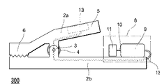
本願発明に係る鍼治療用振動装置100は、図1に示すように、クリップ部材2a、2bから構成される本体の先端側に刺鍼1を挟持する挟持部6と、後端側に振動を発生させる振動部8とを備えている。また、公知技術のものを使用すればよいため図示しないが、電源供給線12を通じて振動部8に電流を供給する電源部と、振動部8と電源部との間に設けられるスイッチとから構成される。尚、振動部8には、ゴミの侵入や防音のために、カバーが付けられる(図6参照)。
以下、具体的に詳述する。
Hereinafter, representative embodiments will be described using the drawings.
Example 1
As shown in FIG. 1, the
The details will be specifically described below.
刺鍼された鍼1の種類は問わない。鍼の代表的な種類として、金鍼、銀鍼、ステンレス鍼があるがどのような鍼でも構わない。柄の形状・材質も問わない。番数も問わない。
本発明は、刺鍼を挟持して振動を与える装置だからである。
本実施例では、(セイリン社製)のステンレス製のディスポ鍼の2番鍼を用いた。
There is no limitation on the type of
This is because the present invention is a device that clamps acupuncture and applies vibration.
In this example, a stainless steel disposable basket (made by Seirin Co., Ltd.) No. 2 was used.
鰐口クリップ形状の本体は、第1のクリップ部材2aと、後端に振動部8を装着した第2のクリップ部材2bをクリップ部材の略中央でピン3により連結し、このピン3に付勢部材として、ねじりコイルバネ4を取付け、このバネ4の付勢力により各クリップ部材2a、2bの先端側を当接させて挟持部6を形成する。また、クリップ部材2aの後端は、押圧することで前記挟持部6を拡開させるつまみ部5を備える。
このつまみ部5を押圧すると、挟持部6が開拡する。この状態で刺鍼1の根本7に挟持部6を当接させて刺鍼1を挟持する。
The hook-clip-shaped main body includes a
When the
クリップ部材2a、2bの材料は、硬質または衝撃を吸収しない材質であれば素材は特に問わない。衝撃を吸収しない材質であることにより、振動部8で発生させた振動は、挟持された刺鍼1に伝えられ、装置100と刺鍼1はともに振動する。装置100の振動は患者の皮膚にも伝えられ、皮膚上にある装置100は不規則に振動する。この振動が患者の皮膚を叩くため、その反作用で装置100は挟持部6が挟持した刺鍼1の根本7を支点として浮き上がったりする。この作用により、刺鍼1に対して上下振動を主とした不規則な振動を与えることができる。さらに皮膚に与えられた振動は、いわゆる、刺入した鍼の周囲の皮膚を鍼管または指で叩いて鍼のヒビキを与える鍼灸術の一つである気拍法と同様の効果を奏し、刺鍼1の振動と相まって治療効果の高い施術が可能となる。
The material of the
具体的な素材としては、抗菌プラスチック等の樹脂や、ステンレスやチタン等の金属でもよい。感染症予防の観点からは、簡易に消毒処理が可能なステンレスが好ましく、金属アレルギーを排除する観点からはチタンが好ましい。また、振動させる本体が軽量であればあるほど振動は強くなるので、金属より更に軽量な抗菌プラスチック等の樹脂であっても良い。
本実施例のクリップ部材においては、消毒処理が簡易にでき、比較的安価であるステンレスを用いた。
また、クリップ部材2a、2bの挟持部6を構成する端部には、刺鍼1を確実に挟持させるために、滑り止め用の凹凸を付してもよい。
As a specific material, a resin such as antibacterial plastic, or a metal such as stainless steel or titanium may be used. From the viewpoint of preventing infectious diseases, stainless steel that can be easily disinfected is preferable, and from the viewpoint of eliminating metal allergy, titanium is preferable. Further, since the vibration is stronger as the body to be vibrated is lighter, a resin such as antibacterial plastic that is lighter than metal may be used.
In the clip member of the present embodiment, stainless steel which is easy to disinfect and relatively inexpensive is used.
Moreover, in order to clamp the
振動部8は、クリップ部材2a、2bから成る本体を振動させ、挟持部6が挟持した刺鍼1に対して振動を与えるものである。よって、刺鍼1に振動を与えられる構成であればよい。本実施例では振動モータを用いる。この振動モータは、モータ9と、そのモータ回転軸10に締結された偏心錘11とから構成されている。
The vibrating
偏心錘11の形状は半円柱状としたが、これに限らず、例えば、扇柱形であってもよい。偏心錘11が回転することでその錘の形状からモータ回転軸10に対してアンバランスな力が加わり、その力が振動として発生すればよいので、特に形状は問わない。
本実施例では、シコー技研製の振動モータ、B2-7717(DC3V駆動)を用いた。
この振動モータを前記クリップ部材2bの後端に、刺鍼1に対してモータ回転軸10が垂直になるように設置する。設置方法は問わない。本実施例では、クリップ部材2bの後端に振動モータを横置きに設置するための振動モータの外径と同じ内径、若しくは、わずかに小さい(0.02ミリ〜1.5ミリ程度)内径の円筒形の台座を設け、その台座の中に偏心錘11が本体の先端側を向くように圧入し、固定した。
The shape of the
In this example, a vibration motor, B2-7717 (DC3V drive) manufactured by Shiko Giken was used.
This vibration motor is installed at the rear end of the
このように、刺鍼1に対して半円状の偏心錘を備えたモータ回転軸10が垂直になる構成としたことにより、刺鍼1に対して上下動への振動を主とした不規則な振動を与えることができる。
As described above, the
また、振動部の他の構成として、図8に示すように、例えばソレノイドを用いて振動させる構成が考えられる。具体的には、クリップ部材2bの内部を中空とし、その内部に直動式ソレノイドアクチュエーター17と、スプリング18(戻りバネ)と、これらに押し出されて可動する可動体21を設置する。ソレノイド17内部の電磁石へ通電することにより、ソレノイド17中の可動磁極20が突出方向に可動する。そして通電が止まると突出した可動磁極20はスプリング18の付勢力によって戻される。このソレノイド17の動きにより可動磁極20が可動体21を押し出し、小刻みに往復移動させて所定周波数の振動を発生させる。
Further, as another configuration of the vibration unit, as shown in FIG. 8, for example, a configuration of vibrating using a solenoid is conceivable. Specifically, the inside of the
クリップ部材2bの内部の形状は、可動体21の当たり面を上方向にするための傾斜部材19を備えている。可動体21は例えば金属製の球状のものを用いる。この可動体21の重さによって振動の強弱を付ける事が可能である。また、この可動体21の直径をクリップ部材2bの高さの半分程度の大きさにすることで、単に左右に往復移動させるだけではなく、傾斜部材19により可動体21を浮き上がらせて上下にも移動させることができる。
The internal shape of the
振動数は例えば100Hz程度に設定することができ、振動の大きさ(振幅)は電圧の設定により制御することができる。 The frequency can be set to about 100 Hz, for example, and the magnitude (amplitude) of the vibration can be controlled by setting the voltage.
他にも、図9に示すようにクリップ部材2bを中空とし、内部に2つの電磁石22と、磁性を有する可動体21を設ける構成が考えられる。この2つ電磁石22に交互に電流を流すことで可動体21を往復させ振動させる構成も考えられる。振動数は例えば100Hz程度に設定することができ、振動の大きさ(振幅)は電圧の設定により制御することができる。この様に、電磁石を使用することにより、刺鍼1に振動刺激だけでなく、磁気による治療効果を与えることもできる。
Besides, as shown in FIG. 9, a configuration is conceivable in which the
電源部には、乾電池を用いるが、振動部8へ電気を供給できればよいので特に形式は問わない。
様々なバッテリーを用いても良いし、既存のAC−DCコンバータを用いてAC100V等の商用電源を使用しても構わない。本実施例では単3電池用の電池ボックスを用いた。
A dry battery is used for the power supply unit, but any type is acceptable as long as electricity can be supplied to the
Various batteries may be used, and a commercial power source such as AC 100 V may be used by using an existing AC-DC converter. In the present embodiment, a battery box for AA batteries was used.
スイッチは、電源部から振動部8へ電気を供給する電源供給線12の間に設け、必要な時以外は刺鍼1に振動を与えないようにする。振動部8へ電流を供給するか否かを任意に制御できれば良いので、特に形式は問わない。
The switch is provided between the
次に、本発明の鍼治療用振動装置100の使用方法について述べる。
Next, a method of using the
まず、鍼灸師が患部に対し鍼を刺鍼操作する。この刺鍼操作は治療の重要な要であって、鍼灸師はなるべく患者に負担を掛けない様、また、臨床上治療効果を与える最適な刺鍼操作する。この刺鍼1の根本7に対し、つまみ部5を押圧し、挟持部6を開拡して、装置100が患者の皮膚上に接地するように刺鍼1の根本7を挟持する。
鍼灸師が再度、刺鍼1と装置100の固定状態や皮膚との接地状態を確認した後、スイッチを入れ、電源部から振動部8に電気を供給し、鍼治療用振動装置100を振動させ、刺鍼1に振動を与える。
First, the acupuncturist performs acupuncture operation on the affected area. This acupuncture operation is an important point of treatment, and the acupuncturist performs an optimal acupuncture operation that gives a therapeutic effect as much as possible so that the patient is not burdened as much as possible. The
After the acupuncturist confirms the fixation state of the
施術時間は、通常の施術であれば3秒から10秒程度、腰痛や肩こりなど、筋肉が硬く硬結していたり、緊張していたりする場合には、1分から2分程振動を与える。患者の筋肉の硬結の硬さや緊張により適宜変更する。 The treatment time is about 3 seconds to 10 seconds in the case of ordinary treatment, and vibration is given for about 1 minute to 2 minutes if the muscles are hard and hardened, such as back pain and stiff shoulders. Change according to the hardness and tension of the patient's muscle consolidation.
施術が終了したら、スイッチを切り、装置100の振動を止める。その後、つまみ部5を押圧し、挟持部6を拡開して鍼1の根本7から挟持部6を取り外し、刺鍼1を抜く。
すべての刺鍼1を抜いた後、感染症予防のため、消毒用アルコールや等で挟持部6を消毒処理する。刺鍼1の根本7は患者の体液と触れ合っているからである。この消毒処理の方法としては、例えば、消毒アルコールやグルタールアルデヒド等をバット等に溜めておき、その液中に浸してあるステンレスの棒材を挟持部6で挟み、挟持部6全体を消毒アルコール等の液中に浸す方法が挙げられる。
When the treatment is finished, the switch is turned off and the vibration of the
After removing all the
電気部材である振動部8は本体の後端側に設置されているので、消毒アルコール等の液量は挟持部を覆う程度、若しくは、より多くても構わない。消毒液に浸す位置を明確にするために、ピン3の周辺に目印となるメモリを付けてもよい。
Since the
このような構成にすることで、挟持部6を確実に消毒処理しつつ、電気部材である振動部8を濡らす恐れを無くすことができる。また、消毒処理後に装置100を回収する際にも、つまみ部5を押圧するだけで済むので、消毒アルコール等を手に付いた雑菌で汚染する虞もない。
By adopting such a configuration, it is possible to eliminate the possibility of wetting the vibrating
このように、鍼治療用振動装置100が患者の皮膚上で上下振動を含む不規則な振動をすることで、刺鍼1にも不規則な振動を与えることができる。また、刺鍼の根本7を挟持することにより、鍼治療用振動装置100がストッパーとなり、刺鍼1が患部の深部まで入り込む虞を無くすことができる。
更に、振動部8が本体の後方に設置されているので、消毒処理の際に挟持部6を完全に消毒アルコール等の液中に浸すことができる。
As described above, the
Furthermore, since the vibrating
また、この鍼治療用振動装置100を使用することにより、刺鍼1に与える振動を、施術時間により定量化することができるので、従来は熟練の鍼灸師しかできなかった手技をだれでも簡単に施術でき、刺激量を明確に把握することができる。
以下、この実験例について述べる。
In addition, by using this
Hereinafter, this experimental example will be described.
被験者を5人用意し、脛にある足三里という経穴に刺鍼を行った。この刺鍼は主に、足のだるさを緩和する刺鍼である。そして、この刺鍼は熟練した鍼灸師の与える手技が無ければ、患者には何らの知覚もない。しかし、熟練の鍼灸師の手技であれば、足先まで細かく振動しているような知覚(いわゆる鍼のヒビキ)が生じる。
被験者1は男性で年齢は30代、2は男性で年齢は20代、3は男性で年齢は50代、4は女性で年齢は30代、5は女性で年齢は50代である。
いずれの被験者も、健康上の疾患は無く、また、鍼治療を受けた経験も無い。
Five test subjects were prepared, and acupuncture points were inserted into the acupuncture points on the shin called “Sansari”. This acupuncture is mainly an acupuncture that relieves dullness. And, this acupuncture does not have any perception to the patient without the procedure given by a skilled acupuncturist. However, in the case of the skill of a skilled acupuncturist, a perception (so-called so-called "hibiki") which vibrates finely to the toes is generated.
The
None of the subjects had any health problems and had never received acupuncture.
この5人の被験者の、右足の脛にある足三里という経穴に、セイリン社製のステンレス製の2番のディスポ鍼を刺鍼操作した。また、刺鍼操作はいずれも鍼灸師の小田氏が行った。 The five stainless steel acupuncture points on the shin of the right foot of the five subjects were subjected to acupuncture operation with a No. 2 stainless steel disposable rod made by Seirin. All the acupuncture operations were performed by Mr. Oda, the acupuncturist.
まず、各被験者に小田氏が刺鍼操作し、刺鍼に対して鍼灸師の熟練の手技である上下振動(雀啄)を10秒間施術し、抜鍼した。 First, Mr. Oda performed an acupuncture operation on each test subject, and applied a vertical vibration (sparrow spear), which is a skillful skill of an acupuncturist, to the acupuncture for 10 seconds.
結果として、被験者全員が脛から足のつま先まで細かな振動(いわゆる鍼のヒビキ)を
を知覚した。
As a result, all subjects perceived fine vibrations (so-called heel cracks) from the shin to the toes of the feet.
その後、同じ被験者に対し、小田氏が同様に刺鍼し、この刺鍼1の根本7に鍼治療用振動装置100を装着し、振動を3秒与えた。被験者が前回の試験と同様の知覚を得られれば、本願装置が刺鍼に対して細かな上下振動を与えていることと、熟練の鍼灸師の手技を再現できたことになる。
Thereafter, Mr. Oda similarly agitated the same subject, and the
結果として、被験者全員が小田氏の手技と同様の知覚を生じた。また、足のだるさも解消した。 As a result, all subjects experienced perceptions similar to Oda's procedure. Also, the dullness of the feet has been resolved.
この結果から、本願装置は刺鍼に対して上下振動を与えており、かつ刺激を定量化し、熟練の鍼灸師の手技を短時間で再現できたと言える。 From this result, it can be said that the device of the present application gave vertical vibrations to the acupuncture, quantified the stimulus, and was able to reproduce the skill of a skilled acupuncturist in a short time.
また、本実施例では、本体のクリップ部材2a,2bをステンレス製としたが、これに限らず安価プラスチック製としても良い。上述したように、アルコールに浸して消毒するのは、「菌」に対しては有効な消毒方法であるが、ウイルスに対しては無効だからである。特に問題となるのはB型肝炎ウイルスである。このウイルスを消毒させるには2%グルタールアルデヒドで器具を30分から1時間浸漬しなければならず、実用的ではない。
よって、簡易、かつ確実に感染症を予防するためには、刺鍼1の根本7に触れた部分を使い捨てにすることが望ましい。刺鍼1の根本7は患者の体液と接触しているからである。
In this embodiment, the
Therefore, in order to prevent infection easily and reliably, it is desirable to make the part of the
例えば、本体と振動部8を脱着可能な構成とすることにより、刺鍼1に触れた本体を使い捨てにすることが挙げられる。
具体的には、図2に示すように、クリップ部材2a、2bのいずれか一方に、振動部8を備えたカバー15を取り付けることが挙げられる。より詳細には、ピン3よりも後方に設置する硬質プラスチック製のカバー15であって、カバー15は後端に振動モータ9の外径と同じ内径か、わずかに小さい(0.02ミリ〜1.5ミリ程度)内径の円筒柱状の台座を設け、その台座の中に振動モータ9を圧入して固定する。カバー15の台座と対向する面は、カバー15と装置本体とを固定する嵌め込み式のクリップ16を設ける。
For example, the main body touching the
Specifically, as shown in FIG. 2, attaching the
このような構成にすることにより、刺鍼1に触れた本体は使い捨てとし、振動モータ9を含む振動部8は嵌め込み式のクリップ16を取り外すことにより繰返し使用することができる。また、振動部8をピン3より後方に取り付けることにより、カバー15が刺鍼1と触れ合う事を確実に防止できる。
By adopting such a configuration, the main body touching the
または、本体後端にスリットを入れた振動モータ9の外径と略同じ内径かわずかに小さい内径の円筒柱形の振動部固定台座を設けておき、その台座中に振動部8を軽く圧入して固定し、施術終了後はスリットから振動モータ9を押し出す構造が挙げられる。または、本体と振動部8のそれぞれに嵌合孔と嵌合突起を設け、互いに嵌合させる構成が挙げられる。
Alternatively, a cylindrical-pillar-shaped vibration portion fixing pedestal having an inner diameter substantially the same as or slightly smaller than the outer diameter of the vibration motor 9 having a slit at the rear end of the main body is provided. And a structure in which the vibration motor 9 is pushed out from the slit after the treatment is completed. Or the structure which provides a fitting hole and a fitting protrusion in each of a main body and the
また、クリップを二つ使う構成も考えられる。刺鍼1の根本7に小型の鰐口クリップを取付け、その小型クリップのクリップ部材の後端を本願装置100の挟持部6で挟持させる。このように、小型クリップは刺鍼1の根本7に接している(患者の体液に触れている)ので使い捨てとし、装置100は施術終了後に回収することができる。
Moreover, the structure which uses two clips is also considered. A small hook clip is attached to the root 7 of the
また、クリップ部材2a、2bのいずれか一方の後端に、振動部8を螺合させる構成としてもよい。例えば、クリップ部材2bの後端に雄ネジ部を設け、これに螺合する雌ネジ部を振動部8の端部に設ける構成とすることができる。
Moreover, it is good also as a structure which screws the
尚、上述した構成は、クリップ部材から構成される本体と、刺鍼1に振動を与える振動部8とを簡易に脱着可能な構成の例示であり、簡易に脱着できるのであれば、その他の構造であっても構わない。
In addition, the structure mentioned above is an illustration of the structure which can detach | desorb easily the main body comprised from a clip member, and the
[実施例2]
本実施例にかかる鍼治療用振動装置20は、図3に示すように、実施例1の鍼治療用振動装置100の振動部8をピン3の後部に、刺鍼1に対してモータ転軸部が水平になるように設置する。このように、ピン3の後ろに振動部8を設置したので、装置本体を小型化することができる。
また、振動部8は挟持部6よりも後端側に設置されているので、挟持部6を消毒アルコール等の液中に浸して消毒処理をすることができる。
尚、振動部の設置方法は問わない。他の構成は実施例1と同様なので説明は省略する。
Example 2
As shown in FIG. 3, the
Moreover, since the
In addition, the installation method of a vibration part does not matter. The other configuration is the same as that of the first embodiment, so the description will be omitted.
図3に示すように、本実施例では、クリップ部材2bのピン3の後部に振動部8を縦置きに設置する円柱筒形の台を設け、その中に偏心錘11が下向きになるように圧入固定した。
As shown in FIG. 3, in the present embodiment, a cylindrical cylindrical base for vertically installing the vibrating
このように、刺鍼1に対して偏心錘11を備えたモータ軸部10が水平になる構成としたことにより、刺鍼1に対して横への振動を主とした上下動を含む不規則な振動を与えることができる。
As described above, the
この横振動は、内調術と称される手技となり、鍼治療として有用な振動である。また、本実施例に係る鍼治療用振動装置200を用いて実験例1と同様の実験を行ったところ、被験者全員が鍼の響きを感じたことから、本実施例の鍼治療用振動装置200でも上下振動を発生させていることが確認できる。
尚、本実施例ではクリップ部材2bに振動部8を設置したが、クリップ部材2aに設置させてもよい。いずれか一方に設置されていればよい。
This lateral vibration is a procedure called internal control and is a useful vibration for acupuncture. In addition, when the same experiment as the experimental example 1 was performed using the acupuncture
In addition, although the
[実施例3]
本実施例にかかる鍼治療用振動装置300は、図4に示すように、実施例1の鍼治療用振動装置100の電源部8を本体に内蔵したことで、電源供給線12を気にせず、無線にて使用可能としたものである。
[Example 3]
As shown in FIG. 4, the vibration device for
図4に示すように鍼治療用振動装置300は、鰐口クリップ形状の本体のつまみ部5周辺に軽量なボタン電池13を装着したものである。この電池13の装着位置は、好ましくは本体横部である。
装置300の上側又は下側とすると、電池13の重みで上下振動を抑制してしまうからである。また、装置300の重心と合わせてしまうと不規則な振動を与える事ができなくなるため、端部が望ましい。
その他の構成は実施例1と同様であるので説明は省略する。
As shown in FIG. 4, the vibrating device for acupuncture and
The upper or lower side of the
The other configuration is the same as that of the first embodiment, so the description will be omitted.
このように、電源部を装置300内部に内包したことにより、無線にて使用可能となった。これにより鍼治療用振動装置300を複数個使用しても電源供給線12が絡まることがなく、施術の簡略化が図れる。また、電池13を本体の横面へ装着することにより、上下振動を抑制する事無く無線化することができる。
As described above, since the power supply unit is included in the
[実施例4]
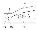
本実施例にかかる鍼治療用振動装置400は、図5に示すように、実施例1に記載した鍼治療用振動装置100、実施例2に記載した鍼治療用振動装置200、実施例3に記載した鍼治療用振動装置300の鰐口クリップ形状の本体の先端側の挟持部6を構成するクリップ部材2a、2bに、治療に使用する鍼の号数(太さ)に合わせて、鍼を固定する固定溝16を付加した構成である。
[Example 4]
As shown in FIG. 5, the vibration device for acupuncture 400 according to the present embodiment includes the
本実施例に係る挟持部6は、図5に示すように挟持部を構成するクリップ部材2a、2bに、刺鍼の固定位置や角度を定めるための固定溝1を有する構成である。
この固定溝1は、刺鍼1と水平方向に、クリップ部材2a、2bを貫通するように設けられる。固定溝14の大きさは鍼の太さにより異なり、例えば、1番鍼から5番鍼までの鍼を固定する小型鍼の固定溝14cは、1番鍼の直径より少し小さい0.16mmφの固定溝を、6番鍼から13番鍼を固定する大型鍼の固定溝14dは、0.20mmφの固定溝を用いる。
これら固定溝14c,14dを、挟持部6に並べて形成する。
The clamping
The fixing
These fixing
尚、挟持させる鍼を間違えないようにするために、固定溝14cと14dとを異なる色に着色してもよい。
The fixing
このような固定溝14を設けたことにより、刺鍼1を確実に固定し、振動を与えることができる。また、刺鍼1を挟持する角度が定まるので、本体と患者の皮膚上との接地を確実にすることができる。更に、鍼灸師が刺鍼1に対して、どちらの固定溝14を使うのかを選択するので、刺鍼の番号や状態を今一度確認する機会を得ることができる。
By providing such a fixing groove 14, it is possible to securely fix the
[実施例5]
本実施例にかかる鍼治療用振動装置500は、図6に示すように、本体の形状をX型にした装置である。その他の構成は実施例1乃至4と同様なので説明は省略する。
[Example 5]
An acupuncture vibration device 500 according to the present embodiment is a device having an X-shaped main body as shown in FIG. The other configuration is the same as that of the first to fourth embodiments, and therefore the description thereof is omitted.
図6に示すように、本体を形成するクリップ部材2a、2bを「へ」の字型に形成する。挟持部6は、「へ」の字型の屈曲部分に形成する。このクリップ部材を組み合わせて本体全体の形状としてはX状の形状とする。
As shown in FIG. 6, the
このように、本体をX状の形状にすることで、患部に設置したときに安定させることができる。 As described above, the X-shaped main body can be stabilized when installed in an affected part.
更に、本実施例の変形例として、クリップ部材の先端を伸長自在にし、振動の強化を図る構成としてもよい。 Furthermore, as a modification of the present embodiment, the clip member may be extensible so that vibration can be enhanced.
例えば、図7に示す通り、への字型のクリップ部材の屈曲部の先端側を、スライド式の二重構造にする構成が挙げられる。クリップ部材の先端側は中空の四角形状のスライドストッパー51が、クリップ部材の外側又は内側の一方には後端側にストッパー突起53を備えたスライドバー52が設置されている。刺鍼1に対して振動を強めたいときは、このスライドバー52を伸ばすことで、重心バランスを偏らせ、振動を強く付加することができる。
For example, as shown in FIG. 7, there is a configuration in which the distal end side of the bent portion of the H-shaped clip member is made a sliding double structure. A hollow rectangular slide stopper 51 is provided on the front end side of the clip member, and a
このように、クリップ部材の先端を伸長自在に構成することにより、本体の重心バランスを更に偏らせることが可能となり、より強い振動を刺鍼に与えることができる。 As described above, by configuring the tip of the clip member to be freely extendable, it is possible to further bias the balance of the center of gravity of the main body, and to apply stronger vibration to the acupuncture.
また、設置の安定化を更に望むのであれば、クリップ部材2a、2b共に上述したようなスライド構造とすればよい。
Further, if it is desired to further stabilize the installation, the
尚、本体の形状は、一例として鰐口クリップやX型の形状を挙げただけであって、他の形状、例えば、卍形状でもよい。クリップコードや、クリップアダプタ、ミノムシクリップや、目玉クリップ、ターンクリップ等、刺鍼を固定することができる形状であればよい。 In addition, the shape of a main body only mentioned the shape of the shed clip and X shape as an example, Comprising: Other shapes, for example, a bowl shape, may be sufficient. The shape may be a clip cord, a clip adapter, a minimus clip, an eyeball clip, a turn clip, or the like as long as the acupuncture can be fixed.
その他、装置本体を、電源供給を兼ねた制御装置と接続することにより、振動数やタイマー等の設定を任意に選択できる構成としてもよい。 In addition, the configuration may be such that the setting of the frequency, the timer, and the like can be arbitrarily selected by connecting the device main body to a control device also serving as a power supply.
制御装置は、例えば、電圧を制御してモータの回転数を制御する電圧制御回路と、その電圧を任意に操作できる操作部と、あらかじめ設定したプログラムを記憶できる記憶部を備える。 The control device includes, for example, a voltage control circuit that controls the voltage to control the rotation speed of the motor, an operation unit that can arbitrarily operate the voltage, and a storage unit that can store a preset program.
操作部は制御装置の外面に備えられ、制御装置の設定電圧の変更の入力を受け付け、電圧制御回路に通知する。 The operation unit is provided on the outer surface of the control device, receives an input of a change in the set voltage of the control device, and notifies the voltage control circuit.
電圧制御回路は既存の物を用いる。アナログ方式でもPWM方式でも構わない。
電圧を制御することができればよい。電圧を制御することにより、簡易にモータの回転数を変化させることができる。このモータの回転数を変化させることで振動の強弱を付けたり、間欠式にしたりすることが可能となる。
The voltage control circuit uses an existing one. It may be either analog or PWM.
It is only necessary to control the voltage. By controlling the voltage, the rotational speed of the motor can be easily changed. By changing the rotation speed of the motor, it becomes possible to add vibration intensity or to make it intermittent.
操作部は、電圧を任意に操作することができればよい。具体的には、スライダーのつまみ位置に応じた電圧をモータに出力させる方法や、ダイヤルの回転量に応じた電圧をモータに出力させる方法、ボタンの押下により、電圧を段階的に変化させる方法などが考えられる。
電圧を上げればモータの回転数を上昇させることが可能となり、下げればモータの回転数を下げることができる。これにより、振動部8の振動の強弱を任意に操作することができる。また、電圧を0に設定することにより、間欠動作させることも可能である。
The operation part should just be able to operate a voltage arbitrarily. Specifically, a method for causing the motor to output a voltage corresponding to the knob position of the slider, a method for outputting a voltage corresponding to the amount of rotation of the dial to the motor, a method for changing the voltage stepwise by pressing a button, etc. Is considered.
If the voltage is increased, the number of rotations of the motor can be increased, and if it is decreased, the number of rotations of the motor can be reduced. Thereby, the strength of vibration of the
記憶部は、予め設定したプログラムを記憶する部分である。
操作部により、鍼の番号に合わせたプログラムが選択されると、記憶部が予め設定されたプログラムを電圧制御部へ指示する。
予め設定されたプログラムとしては、例えば、2番鍼の使用時にはモータの回転数を8000回転とし、駆動時間を3秒、休止時間を10秒でこれを5回繰り返すプログラムとしたり、5番鍼の場合は10000回転とし、駆動時間を10秒、休止時間を10秒でこれを8回繰り返すプログラム等にしたりするプログラムが挙げられる。いずれのプログラムも、施術者が任意に設定することができる。その他、施術に合わせたタイマー等を記憶しても良い。
The storage unit is a portion that stores a preset program.
When the operation unit selects a program according to the eyebrow number, the storage unit instructs the voltage control unit of the preset program.
As a preset program, for example, the number of revolutions of the motor is 8000 when using the second gear, the driving time is 3 seconds, the pause time is 10 seconds, and the program is repeated five times. In this case, there is a program such as a program in which the number of revolutions is 10,000, the driving time is 10 seconds, the pause time is 10 seconds, and this is repeated 8 times. Any program can be optionally set by the practitioner. Besides, a timer or the like may be stored according to the treatment.
また、制御装置には、鍼治療用振動装置を複数接続することができる構成としてもよい。 Further, the control device may be configured such that a plurality of vibration devices for acupuncture can be connected.
本願発明に係る鍼治療振動装置には、振動を増幅させるための様々な構成を付加してもよい。例えば、一端に固定用の穴を開けた厚さ1mmから2mm程度のステンレス製の振動板をクリップ部材2a、2bを連結しているピン3で固定し、モータ回転軸10に取り付けた偏心錘11でこの振動板を叩いて上下の振動を増幅する構成としてもよい。この場合の偏心錘11は、振動板と直接接触するので、面を有するものが好ましい。例えば、振動を最も増幅するのならば、回転重心を大きくずらせる扇形柱の形状が好ましい。また、偏心錘11を使用しなくとも、ギアを介して直接上下に振動させる構成としてもよい。
Various configurations for amplifying the vibration may be added to the acupuncture and treatment vibration apparatus according to the present invention. For example, an
その他、本体下面に予め一定温度、例えば46度に設定されたヒータを設置し、本体に内蔵したサーミスターで温度の検出をし、制御する構成としてもよい。
このように、鍼に対する振動治療だけでなく、温熱効治療を付与させてもよい。
In addition, a heater set in advance at a constant temperature, for example, 46 degrees may be installed on the lower surface of the main body, and the temperature may be detected and controlled by a thermistor built in the main body.
Thus, not only the vibration treatment for wrinkles but also a thermal effect treatment may be given.
1 刺鍼
2a 第1クリップ部材
2b 第2クリップ部材
3 ピン
4 バネ
5 つまみ部
6 挟持部
7 刺鍼の根本部
8 振動部
9 モータ
10 モータ回転軸
11 偏心錘
100 鍼治療用振動装置
12 電源供給線
13 ボタン電池
14c 固定溝
14d 固定溝
15 脱着式カバー
16 嵌込み式クリップ
17 ソレノイド
18 スプリング
19 傾斜部材
20 可動電極
21 可動体
22 電磁石
51 スライドストッパー
52 スライドバー
53 ストッパー突起
DESCRIPTION OF
Claims (3)
前記挟持部が挟持した鍼に与えられる振動を回転運動によって発生させるモータ部と、
前記挟持部と前記モータ部を有する本体と、
を備えた鍼治療用振動装置であって、
前記鍼治療用振動装置は、前記本体の端部であって前記挟持部が設けられた前記本体の端部に対して反対側の前記本体の端部であるとともに、前記本体の重心から離れた位置に前記モータ部を備え、前記鍼を刺鍼する方向において前記本体の移動が制限されることで前記鍼に与えられる振動を不規則な振動とする鍼治療用振動装置。 A pinching portion for pinching a weir;
A motor unit that generates, by rotational movement, a vibration applied to the crucible held by the clamping unit;
And the body having the motor unit and the clamping unit,
A vibrating device for treating acupuncture, comprising
The vibration device for acupuncture is an end of the main body that is the end of the main body and opposite to the end of the main body provided with the clamping portion, and is separated from the center of gravity of the main body A vibration device for acupuncture treatment that includes the motor unit at a position, and causes vibration applied to the heel to be irregular when the movement of the main body is restricted in a direction to puncture the heel.
前記第1のクリップ部材に対向して設けられ、前記第1のクリップ部材に揺動可能に連結される第2のクリップ部材と、
前記第1のクリップ部材の先端部と前記第2のクリップ部材の先端部とを互いに接近させる方向に付勢する付勢手段と、
前記第1のクリップ部材の先端部と前記第2のクリップ部材の先端部とにより形成され、前記付勢手段により刺鍼後の前記鍼を挟持する前記挟持部と、
前記第2のクリップ部材に、押圧することで前記挟持部を拡開させるつまみ部と、
を備える鰐口クリップの形状であって、
前記第1のクリップ部材の前記本体の重心からずれた位置であって、前記挟持部から前記つまみ部より離れた位置に前記モータ部を固定する円筒形の台座を備えたことを特徴とする請求項1に記載の鍼治療用振動装置。 The body is a first clip member;
A second clip member provided opposite to the first clip member and pivotably connected to the first clip member;
Biasing means for biasing the distal end of the first clip member and the distal end of the second clip member in a direction to make them approach each other;
The clamping portion formed by the distal end portion of the first clip member and the distal end portion of the second clip member, and sandwiching the heel after acupuncture by the biasing means;
A knob portion for expanding the sandwiching portion by pressing the second clip member;
In the shape of a shed clip comprising
A cylindrical pedestal for fixing the motor unit at a position deviated from the center of gravity of the main body of the first clip member and distant from the pinching part from the knob part is provided. An oscillating device for acupuncture according to Item 1.
Priority Applications (1)
| Application Number | Priority Date | Filing Date | Title |
|---|---|---|---|
| JP2014229798A JP6552805B2 (en) | 2014-11-12 | 2014-11-12 | Acupuncture vibration device and method of using acupuncture vibration device |
Applications Claiming Priority (1)
| Application Number | Priority Date | Filing Date | Title |
|---|---|---|---|
| JP2014229798A JP6552805B2 (en) | 2014-11-12 | 2014-11-12 | Acupuncture vibration device and method of using acupuncture vibration device |
Publications (3)
| Publication Number | Publication Date |
|---|---|
| JP2016093235A JP2016093235A (en) | 2016-05-26 |
| JP2016093235A5 JP2016093235A5 (en) | 2017-12-14 |
| JP6552805B2 true JP6552805B2 (en) | 2019-07-31 |
Family
ID=56069789
Family Applications (1)
| Application Number | Title | Priority Date | Filing Date |
|---|---|---|---|
| JP2014229798A Active JP6552805B2 (en) | 2014-11-12 | 2014-11-12 | Acupuncture vibration device and method of using acupuncture vibration device |
Country Status (1)
| Country | Link |
|---|---|
| JP (1) | JP6552805B2 (en) |
Families Citing this family (2)
| Publication number | Priority date | Publication date | Assignee | Title |
|---|---|---|---|---|
| CN114533545A (en) * | 2021-07-14 | 2022-05-27 | 宋云洪 | Acupuncture device for traditional Chinese medicine clinical use |
| KR102628561B1 (en) * | 2022-03-08 | 2024-01-30 | 동신대학교산학협력단 | Ultra-small device with adjustable vibration direction for vibrating needle treatment |
Family Cites Families (4)
| Publication number | Priority date | Publication date | Assignee | Title |
|---|---|---|---|---|
| JPH0249534U (en) * | 1988-09-27 | 1990-04-06 | ||
| GB2327975B (en) * | 1997-07-30 | 2001-10-24 | Ivor Barrie Langford | Holding device |
| KR200356688Y1 (en) * | 2004-04-14 | 2004-07-19 | 신치호 | A heating apparatus for a needle |
| KR101438522B1 (en) * | 2012-12-24 | 2014-09-15 | 대구한의대학교산학협력단 | Apparatus for operating vibration needle |
-
2014
- 2014-11-12 JP JP2014229798A patent/JP6552805B2/en active Active
Also Published As
| Publication number | Publication date |
|---|---|
| JP2016093235A (en) | 2016-05-26 |
Similar Documents
| Publication | Publication Date | Title |
|---|---|---|
| US4962758A (en) | Vibratory device for releasing air bubbles trapped in the heart muscle | |
| JP4744968B2 (en) | Treatment equipment | |
| JP4945073B2 (en) | Device for electrotherapy | |
| JP2003038593A (en) | Control method for massage machine | |
| JP6552805B2 (en) | Acupuncture vibration device and method of using acupuncture vibration device | |
| JP3187462U (en) | Intraoral massager | |
| JP6285142B2 (en) | Electric magnet beauty massager | |
| KR101438522B1 (en) | Apparatus for operating vibration needle | |
| JP7452882B2 (en) | tattoo equipment | |
| KR101637101B1 (en) | A treatment tool for oriental finger pressing | |
| KR101551551B1 (en) | Device for 3-axis motorized neddle oscillating | |
| JP2009247811A (en) | Percutaneous penetration device using ultrasonic wave | |
| KR100978414B1 (en) | Acupressure instrument for massage | |
| KR200354756Y1 (en) | Electric vibration massager | |
| JP3156487U (en) | Electric massager | |
| JP3240315U (en) | sonic vibration acupuncture | |
| KR200353371Y1 (en) | massage stick | |
| JP2001104448A (en) | Cupping method and cupping device | |
| KR20060128589A (en) | Magnetic vibrator for head health | |
| KR200483673Y1 (en) | Apparatus for acupressure | |
| KR200394391Y1 (en) | Magnetic vibrator for head health | |
| KR200330400Y1 (en) | Vibrational finger-pressure bar | |
| JP2003260102A (en) | Skin stimulating treatment device using quartz crystal | |
| KR200446670Y1 (en) | A massage device for a foot | |
| KR200396484Y1 (en) | Magnetic vibrator for head health |
Legal Events
| Date | Code | Title | Description |
|---|---|---|---|
| A521 | Request for written amendment filed |
Free format text: JAPANESE INTERMEDIATE CODE: A523 Effective date: 20171105 |
|
| A621 | Written request for application examination |
Free format text: JAPANESE INTERMEDIATE CODE: A621 Effective date: 20171109 |
|
| A521 | Request for written amendment filed |
Free format text: JAPANESE INTERMEDIATE CODE: A523 Effective date: 20171208 |
|
| A977 | Report on retrieval |
Free format text: JAPANESE INTERMEDIATE CODE: A971007 Effective date: 20180831 |
|
| A131 | Notification of reasons for refusal |
Free format text: JAPANESE INTERMEDIATE CODE: A131 Effective date: 20181002 |
|
| A521 | Request for written amendment filed |
Free format text: JAPANESE INTERMEDIATE CODE: A523 Effective date: 20181130 |
|
| A131 | Notification of reasons for refusal |
Free format text: JAPANESE INTERMEDIATE CODE: A131 Effective date: 20190219 |
|
| A521 | Request for written amendment filed |
Free format text: JAPANESE INTERMEDIATE CODE: A523 Effective date: 20190410 |
|
| TRDD | Decision of grant or rejection written | ||
| A01 | Written decision to grant a patent or to grant a registration (utility model) |
Free format text: JAPANESE INTERMEDIATE CODE: A01 Effective date: 20190625 |
|
| A61 | First payment of annual fees (during grant procedure) |
Free format text: JAPANESE INTERMEDIATE CODE: A61 Effective date: 20190703 |
|
| R150 | Certificate of patent or registration of utility model |
Ref document number: 6552805 Country of ref document: JP Free format text: JAPANESE INTERMEDIATE CODE: R150 |
|
| R250 | Receipt of annual fees |
Free format text: JAPANESE INTERMEDIATE CODE: R250 |
|
| R250 | Receipt of annual fees |
Free format text: JAPANESE INTERMEDIATE CODE: R250 |